Acura RSX Honda Integra. Manual - part 119
01
02
S6M6AAJK72100090335FAAT10
−
−
−
−
−
−
DTC P0335:
DTC P0336:
DTC P0339:
YES
NO
YES
NO
YES
NO
11-182
PGM-FI System
DTC Troubleshooting (cont’d)
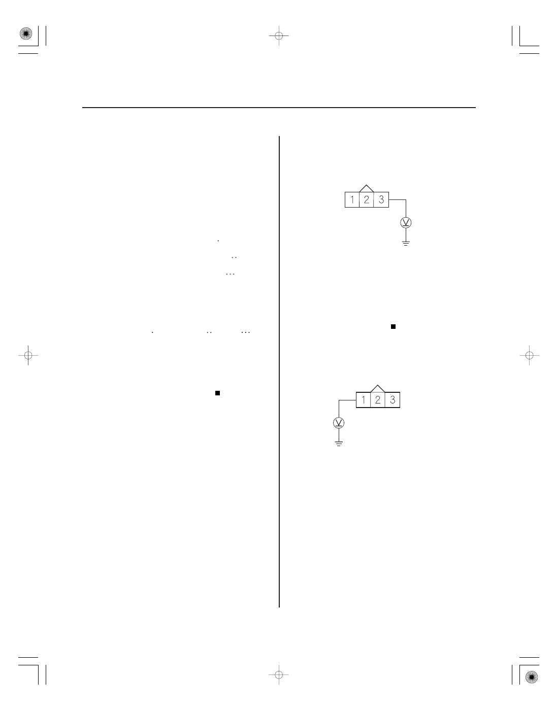
CKP SENSOR 3P CONNECTOR
IGP
(YEL/BLK)
CKP SENSOR 3P CONNECTOR
CKP
(BLU)
CKP Sensor No Signal
(2002-2004 models)
CKP Sensor Circuit Intermittent
Interruption
(2002-2003 models)
CKP Sensor Circuit Intermittent
Interruption
(2004 model)
NOTE:
• Information marked with an asterisk ( ) applies to
2002-2004 models.
• Information marked with double asterisk (
) applies
to 2002-2003 models.
• Information marked with triple asterisk (
) applies
to 2004 model.
1. Reset the ECM/PCM (see page 11-4).
2. Start the engine.
Go to step 3.
Intermittent failure, system is OK at this time.
Check for poor connections or loose terminals at
the CKP sensor and the ECM/PCM.
3. Turn the ignition switch OFF.
4. Disconnect the CKP sensor 3P connector.
5. Turn the ignition switch ON (II).
6. Measure voltage between CKP sensor 3P connector
terminal No. 3 and body ground.
Go to step 7.
Repair open in the wire between PGM-FI main
relay 1 and the CKP sensor.
7. Measure voltage between CKP sensor 3P connector
terminal No. 1 and body ground.
Go to step 8.
Go to step 10.
Wire side of female terminals
Wire side of female terminals
Is DT C P0335 and/ or ( P0336)
( P0339)
indicated?
Is ther e batter y voltage?
Is ther e about 5 V ?
05/06/27 17:35:45 61S6M040_110_0182