Acura RSX Honda Integra. Manual - part 54


  Index      Acura     Acura RSX Honda Integra - service repair manual 2002-2006 year


Search            


Content   ..  52  53  54  55   ..


Acura RSX Honda Integra. Manual - part 54


01

S6M6A00A18316617502KBAT00

Main Bearing Clearance Inspection

Main Bearing-to-Journal Oil Clearance
No. 1, 2, 4, 5 Journals:
Standard (New): 0.017

0.041 mm

(0.0007

0.0016 in.)

Service Limit:

0.050 mm (0.0020 in.)

No. 3 Journal:
Standard (New): 0.025

0.049 mm

(0.0010

0.0019 in.)

Service Limit:

0.055 mm (0.0022 in.)

7-6

Engine Block

Crankshaft Main Bearing Replacement

1. To check main bearing-to-journal oil clearance,

remove the lower block and bearing half (see page
7-13).

2. Clean each main journal and bearing half with a

clean shop towel.

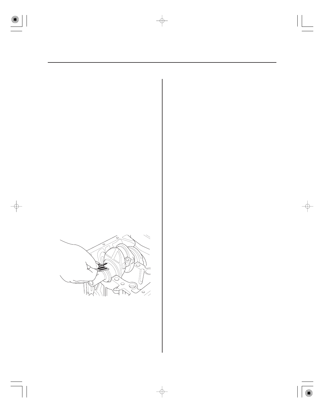
3. Place one strip of plastigage across each main

journal.

4. Reinstall the bearing half and lower block, then

torque the bolts to 29 N·m (3.0 kgf·m, 22 lbf·ft)

56 °.

NOTE: Do not rotate the crankshaft during
inspection.

5. Remove the lower block and bearing half again,

and measure the widest part of the plastigage.

6. If the plastigage measures too wide or too narrow,

remove the crankshaft, and remove the upper half
of the bearing. Install a new, complete bearing with
the same color code(s), and recheck the clearance.
Do not file, shim, or scrape the bearings or the caps
to adjust clearance.

7. If the plastigage shows the clearance is still

incorrect, try the next larger or smaller bearing (the
color listed above or below that one), and check
again. If the proper clearance cannot be obtained
by using the appropriate larger or smaller bearings,
replace the crankshaft and start over.

02

03

04

Main Bearing Selection

Crankshaft Bore Code Location

Main Journal Code Location

7-7

No. 5 JOURNAL
(FLYWHEEL END)

No. 1 JOURNAL
(PULLEY END)

No. 1 JOURNAL

No. 5 JOURNAL

1. Numbers or letters or bars have been stamped on

the end of the block as a code for the size of each of
the five main journal bores. Write down the crank
bore codes.
If you can’t read the codes because of accumulated
dirt and dust, do not scrub them with a wire brush
or scraper. Clean them only with solvent or
detergent.

2. The main journal codes are stamped on the

crankshaft.

(cont’d)

05

01

S6M6A00A18316217201KBAT00

Rod Bearing Clearance Inspection

Tightening Torque
K20A3 Engine:

20 N·m (2.0 kgf·m, 14 lbf·ft)

90 °

K20A2, K20Z1 Engines: 29 N·m (3.0 kgf·m, 22 lbf·ft)

90 °

Connecting Rod Bearing-to-Journal Oil Clearance
K20A3 Engine:
Standard (New): 0.020

0.050 mm

(0.0008

0.0020 in.)

Service Limit:

0.060 mm (0.0024 in.)

K20A2, K20Z1 Engines:
Standard (New): 0.033

0.061 mm

(0.0013

0.0024 in.)

Service Limit:

0.072 mm (0.0028 in.)

7-8

7-8

Engine Block

Crankshaft Main Bearing
Replacement (cont’d)

Connecting Rod Bearing
Replacement

Larger crank bore

1 or
A or I

2 or
B or II

3 or
C or III

4 or
D or IIII

Smaller bearing (Thicker)

Blue

Pink

Yellow

Green

Green/
Brown

Brown

Green

Green/
Brown

Brown

Green

Green/
Brown

Brown

Green

Green/
Brown

Brown

Black

Black/
Blue

Crank
bore
code

Main
journal
code

1

2

3

4

5

6

Smaller
main
journal

Smaller
bearing
(Thicker)

Pink/
Yellow

Yellow

Yellow

Pink/
Yellow

Black

Black

Black/
Blue

3. Use the crank bore codes and crank journal codes

to select the appropriate replacement bearings
from the following table.

NOTE:

• Color code is on the edge of the bearing.
• When using bearing halves of different colors, it

does not matter which color is used in the top or
bottom.

1. Remove the oil pump (see page 8-13).

2. Remove the baffle plate (see step 7 on page 7-13).

3. Remove the connecting rod cap and bearing half.

4. Clean the crankshaft rod journal and bearing half

with a clean shop towel.

5. Place plastigage across the rod journal.

6. Reinstall the bearing half and cap, and torque the

bolts.

NOTE: Do not rotate the crankshaft during
inspection.

7. Remove the rod cap and bearing half, and measure

the widest part of the plastigage.

01

Rod Bearing Selection

Connecting Rod Big End Bore Code Locations

Normal Bore Size
K20A3 Engine:

48.0 mm (1.89 in.)

K20A2, K20Z1 Engines: 51.0 mm (2.01 in.)

7-9

8. If the plastigage measures too wide or too narrow,

remove the upper half of the bearing, install a new,
complete bearing with the same color code(s), and
recheck the clearance. Do not file, shim, or scrape
the bearings or the caps to adjust clearance.

9. If the plastigage shows the clearance is still

incorrect, try the next larger or smaller bearing (the
color listed above or below that one), and check
clearance again. If the proper clearance cannot be
obtained by using the appropriate larger or smaller
bearing, replace the crankshaft and start over.

1. Inspect each connecting rod for cracks and heat

damage.

2. Each rod has a tolerance range from 0 to 0.024 mm

(0.0009 in.), in 0.006 mm (0.0002 in.) increments,
depending on the size of its big end bore. It’s then
stamped with a number or bar (1, 2, 3 or 4/l, ll, lll, or
llll) indicating the range. You may find any
combination of numbers and bars in any engine,
(Half the number or bar is stamped on the bearing
cap, the other half on the rod).

If you can’t read the code because of an
accumulation of oil and varnish, do not scrub it
with a wire brush or scraper. Clean it only with
solvent or detergent.

(cont’d)


Content   ..  52  53  54  55   ..