Acura RSX Honda Integra. Manual - part 55
02
03
01
02
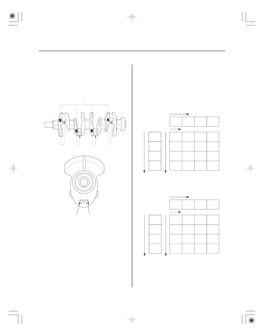
Connecting Rod Journal Code Location
Connecting Rod Journal Code Location
(Letters or Bars)
K20A3 engine:
K20A2, K20Z1 engines:
7-10
Engine Block
Connecting Rod Bearing Replacement (cont’d)
No. 1 JOURNAL
No. 4 JOURNAL
Larger big end bore
Smaller bearing (Thicker)
1 or I
2 or II
3 or III
4 or IIII
Green/
Brown
Black
Yellow/
Green
Brown
Pink/
Yellow
Green
Brown
Blue
Big end
bore
code
Yellow
Pink
Green
Brown/
Black
Brown/
Black
Green/
Brown
Yellow/
Green
Black/
Blue
Smaller
rod
journal
Smaller
bearing
(Thicker)
Rod
journal
code
Larger big end bore
Smaller bearing (Thicker)
1 or I
2 or II
3 or III
4 or IIII
Green
Black
Brown
Yellow
Pink
Yellow
Green
Brown
Red
Pink
Yellow
Green
Green
Brown
Black
Blue
Big end
bore
code
Smaller
rod
journal
Smaller
bearing
(Thicker)
Rod
journal
code
A
B
C
D
A
B
C
D
3. The connecting rod journal codes are stamped on
the crankshaft.
4. Use the big end bore codes and rod journal codes
to select appropriate replacement bearings from
the following table.
NOTE:
• Color code is on the edge of the bearing.
• When using bearing halves of different colors, it
does not matter which color is used in the top or
bottom.