Acura RL. Manual - part 512


  Index      Acura     Acura RL - service repair manual 2005-2008 year


Search            


Content   ..  510  511  512  513   ..


Acura RL. Manual - part 512


PCM INPUTS AND OUTPUTS AT CONNECTOR D (17P) 

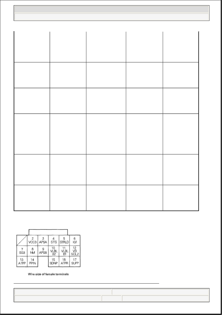
Fig. 24: Identifying PCM Inputs And Outputs Connector Terminals D (17P) 
Courtesy of AMERICAN HONDA MOTOR CO., INC.

With engine 
running in N, P, R, 
D (in 2nd, 4th 
gears), D3, and M 
positions: about 0 
V

18

RED

ATPD3 
(TRANSMISSION 
RANGE SWITCH 
D3)

Detects 
transmission range 
switch D3 signal

In D3 position: 
about 0 V 
In any position 
other than D3: 
battery voltage

19

BLU/YEL

ATPFWD 
(TRANSMISSION 
RANGE SWITCH 
D3/D)

Detects 
transmission range 
switch D3/D signal

In D, D3 positions: 
about 0 V 
In any other 
position: battery 
voltage

20

BLU/YEL

OP4SW (4TH 
CLUTCH 
TRANSMISSION 
FLUID PRESSURE 
SWITCH)

Detects 4th clutch 
transmission fluid 
pressure switch 
input

With ignition 
switch ON (II): 
Without 4th clutch 
pressure: about 5.0 

With 4th clutch 
pressure: about 0 
V

21

RED/WHT

ATPRVS 
(TRANSMISSION 
RANGE SWITCH R 
POSITION)

Detects 
transmission range 
switch P, R, neutral 
position signal 
input

In P, R, N 
positions: about 0 

In any other 
position: battery 
voltage

22

GRN/RED

LSC (A/T CLUTCH 
PRESSURE 
CONTROL 
SOLENOID VALVE 
C)

Drives A/T clutch 
pressure control 
solenoid valve C

With ignition 
switch ON (II): 
pulses


2007 Acura RL 

2005-08 ENGINE PERFORMANCE Fuel and Emissions Systems - RL


me 


Friday, June 05, 2009 2:33:27 PM

Page 43 

© 2005 Mitchell Repair Information Company, LLC. 

CONNECTOR TERMINAL DESCRIPTION CHART 

NOTE:

Standard battery voltage is about 12 V.

Terminal number

Wire color

Terminal name

Description

Signal

2

RED

VCC3 (SENSOR 
VOLTAGE)

Provides sensor 
voltage

With ignition 
switch ON (II): 
about 5.0 V 
With ignition 
switch OFF: about 
0 V

3

PUR

APSA 
(ACCELERATOR 
PEDAL POSITION 
(APP) SENSOR A)

Detects APP sensor 
A signal

With ignition 
switch ON (II) and 
accelerator pedal 
pressed: about 4.5 

With ignition 
switch ON (II) and 
accelerator pedal 
released: about 1.0 
V

4

LT BLU

STS (STARTER 
SWITCH SIGNAL)

Detects starter 
switch signal

With starter switch 
ON (III): battery 
voltage 
With starter switch 
OFF: about 0 V

5

PNK

STRLD

Detects starter cut 
relay 2 (STCUT)

With starter ON: 
battery voltage

6

YEL

IG1 (IGNITION 
SIGNAL)

Detects ignition 
signal

With ignition 
switch ON (II): 
battery voltage 
With ignition 
switch OFF: about 
0 V

7

WHT

SG3 (SENSOR 
GROUND)

Sensor ground

Less than 1.0 V at 
all times

8

RED

NM (INPUT SHAFT 
(MAINSHAFT) 
SPEED SENSOR)

Detects input shaft 
(mainshaft) speed 
sensor signals

With ignition 
switch ON (II): 
about 0 V or about 
5.0 V 
With engine idling 
in N position: about 
2.5 V (pulses)

9

LT GRN

APSB 
(ACCELERATOR 
PEDAL POSITION 
(APP) SENSOR B)

Detects APP sensor 
B signal

With ignition 
switch ON (II) and 
accelerator pedal 
pressed: about 2.3 

With ignition 
switch ON (II) and 


2007 Acura RL 

2005-08 ENGINE PERFORMANCE Fuel and Emissions Systems - RL


me 


Friday, June 05, 2009 2:33:27 PM

Page 44 

© 2005 Mitchell Repair Information Company, LLC. 

accelerator pedal 
released: about 0.5 
V

10

GRY

VLBLB2 (LABEL 
RESISTER BANK 
2)

Detects front A/F 
sensor (Bank 2, 
sensor 1) LABEL 
signal

With engine 
running: about 0.4-
4.6 V

11

WHT

VLBLB1 (LABEL 
RESISTER BANK 
1)

Detects rear A/F 
sensor (Bank 1, 
sensor 1) LABEL 
signal

With engine 
running: about 0.4-
4.6 V

12

ORN

VBSOL2 (POWER 
SOURCE FOR 
SOLENOID 
VALVES)

Power source for 
solenoid valves

With ignition 
switch ON (II): 
battery voltage 
With ignition 
switch OFF: about 
0 V

13

GRN

ATPP 
(TRANSMISSION 
RANGE SWITCH P)

Detects 
transmission range 
switch P signal

In P position: about 
0 V 
In any position 
other than P: 
battery voltage

14

LT BLU

PPIN (PARK PIN 
SWITCH)

Detects park pin 
switch signal

With ignition 
switch ON (II) in P 
position: battery 
voltage 
With ignition 
switch ON (II) in 
other than P 
position: about 0V

15

PUR

SDNP

Detects paddle 
shifter - (downshift 
switch) signal

In M position, 
paddle shifter - 
(downshift switch) 
pressed: about 0 V
In M position, 
paddle shifter - 
(downshift switch) 
released: battery 
voltage

16

PUR

ATPR 
(TRANSMISSION 
RANGE SWITCH R 
POSITION)

Detects 
transmission range 
switch R signal 
input

In R position: about 
0 V 
In any position 
other than R: 
battery voltage

17

BLU

SUPP

Detects paddle 
shifter + (upshift 
switch) signal

In M position, 
paddle shifter + 
(upshift switch) 
pressed: about 0 V
In M position, 
paddle shifter + 


2007 Acura RL 

2005-08 ENGINE PERFORMANCE Fuel and Emissions Systems - RL


me 


Friday, June 05, 2009 2:33:27 PM

Page 45 

© 2005 Mitchell Repair Information Company, LLC. 

PCM INPUTS AND OUTPUTS AT CONNECTOR E (31P) 

Fig. 25: Identifying PCM Inputs And Outputs Connector Terminals E (31P) 
Courtesy of AMERICAN HONDA MOTOR CO., INC. 

CONNECTOR TERMINAL DESCRIPTION CHART 

(upshift switch) 
released: battery 
voltage

NOTE:

Standard battery voltage is about 12 V.

Terminal number

Wire color

Terminal name

Description

Signal

1

GRN

SG4 (SENSOR 
GROUND)

Sensor ground

Less than 1.0 V at 
all times

2

BRN

IMOFPR 
(IMMOBILIZER 
FUEL PUMP 
RELAY)

Drives PGM-FI 
main relay 2 (FUEL 
PUMP)

0 V for 2 seconds 
after turning 
ignition switch ON 
(II), then battery 
voltage

3

BLU

DBWRLY 
(THROTTLE 
ACTUATOR 
CONTROL 
MODULE (DBW) 
RELAY)

Drives throttle 
actuator control 
module (DBW) 
relay

With ignition 
switch ON (II): 
about 0 V

4

PNK

AFSHTCR (AIR 
FUEL RATIO (A/F) 
SENSOR RELAY)

Drives A/F sensor 
relay

With ignition 
switch ON (II): 
about 0 V

5

GRN

MRLY (PGM-FI 
MAIN RELAY)

Drives PGM-FI 
main relay 1 (FI 
MAIN) 
Power source for 
DTC memory

With ignition 
switch ON (II): 
about 0 V 
With ignition 
switch OFF: 
battery voltage

6

LT BLU

RFC (RADIATOR 
FAN CONTROL 
UNIT)

Drives radiator fan 
control unit

With ignition 
switch ON (II): 
about 0 V


2007 Acura RL 

2005-08 ENGINE PERFORMANCE Fuel and Emissions Systems - RL


me 


Friday, June 05, 2009 2:33:27 PM

Page 46 

© 2005 Mitchell Repair Information Company, LLC. 


Content   ..  510  511  512  513   ..