Acura CSX. Manual - part 674


  Index      Acura     Acura CSX - P/NO. 61SNR03 - service repair manual 2006-2009 year


Search            


Content   ..  672  673  674  675   ..


Acura CSX. Manual - part 674


01

SNR9A00H46400000000AAAT00

General Precautions

Steering-related Precautions

Cable Reel Alignment

24-13

Precautions and Procedures

NOTE: Some systems store data in memory that is lost
when the battery is disconnected. Before disconnecting
the battery, refer to Battery Terminal Disconnection and
Reconnection (see page 22-68).

Please read the following precautions carefully before
servicing the airbag system. If the instructions
described in this manual are not properly followed, or
the airbags could accidentally deploy and cause
damage or injuries.

• Except when doing electrical inspections, always turn

the ignition switch to LOCK (0), disconnect the
negative cable from the battery, then wait at least
3 minutes before starting work.

NOTE: The SRS memory is not cleared even if the
ignition switch is turned to LOCK (0), or the battery
cables are disconnected from the battery.

• Use replacement parts which are manufactured to the

same standards and quality as the original parts. Do
not install used SRS parts. Use only new parts when
making SRS repairs.

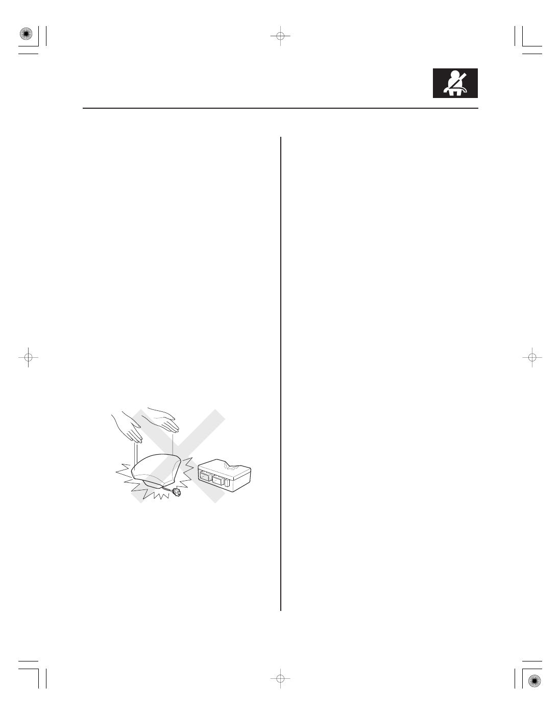
• Carefully inspect any SRS part before you install it.

Do not install any part that shows signs of being
dropped or improperly handled, such as dents, cracks
or deformation.

• Before disconnecting the SRS unit connectors,

always disconnect the appropriate SRS parts
connectors.

• Use only a digital multimeter to check the system. If it

is not a Honda multimeter, make sure its output is
10 mA (0.01 A) or less when switched to the lowest
value in the ohmmeter range. A tester with a higher
output could cause accidental deployment and
possible injury.

• Do not put objects on the front passenger’s airbag.

• The original audio and navigation system have a

coded theft protection circuit. Make sure you have the
anti-theft codes for the audio system or navigation
system (if equipped), then write down the audio
presets before disconnecting the negative cable from
the battery.

• Before returning the vehicle to the client, enter the

anti-theft codes for the audio system or navigation
system (if equipped), then enter the audio presets; set
the clock.

• Misalignment of the cable reel could cause an open in

the wiring, making the SRS system, remote steering
wheel controls, or the horn inoperative. Center the
cable reel whenever you do the following (see step 6
on page 24-202).
– Installation of the steering wheel
– Installation of the cable reel
– Installation of the steering column
– Other steering-related adjustment or installation

• Do not disassemble the cable reel.

• Do not apply grease to the cable reel.

• If the cable reel shows any signs of damage, replace

it with a new one. For example, if the cable reel does
not rotate smoothly, replace it.

08/08/21 13:54:18 61SNR030_240_0013

02

03

04

05

06

Airbag Handling and Storage

24-14

SRS

A

C

B

C

Do not disassemble an airbag. It has no serviceable
parts. Once an airbag has been deployed, it cannot be
repaired or reused.

For temporary storage of an airbag during service,
observe the following precautions.

• Store the removed airbag with the pad surface up.

Never put anything on the airbag.

• To prevent damage to the airbag, keep it away from

any oil, grease, detergent, or water.

• Store the removed airbag on a secure, flat surface

away from any high heat source (exceeding 200 °F/
93 °C).

• Never perform electrical inspections to the airbags,

such as measuring resistance.

• Do not position yourself in front of the airbag during

removal, inspection, or replacement.

• For proper disposal of a damaged airbag, refer to

airbag disposal (see page 24-196).

• The side curtain airbag module assembly is a long,

jointed part containing an inflator (A), a flexible bag
(B), and brackets (C). When removing or installing the
side curtain airbag assembly, never:
– Handle the flexible bag.
– Drop the airbag assembly.
– Cut, tear, or unwrap the taps strips.

08/08/21 13:54:18 61SNR030_240_0014

07

08

SRS Unit, Front and Side Impact Sensors,
Driver’s Seat Position Sensor, Front
Passenger’s Weight Sensors and, Rear
Safing Sensor

24-15

NOTE: Some systems store data in memory that is lost
when the battery is disconnected. Before disconnecting
the battery, refer to Battery Terminal Disconnection and
Reconnection (see page 22-68).

• Turn the ignition switch to LOCK (0), disconnect the

negative cable from the battery, then wait at least 3
minutes before starting installation or replacement of
the SRS unit, or disconnecting the connectors from
the SRS unit.

• Be careful not to bump or impact the SRS unit, the

front impact sensors, the side impact sensors, or the
rear safing sensor whenever the ignition switch is in
ON (II), or for at least 3 minutes after the ignition
switch is turned to LOCK (0).

• During installation or replacement, be careful not to

bump (by impact wrench, hammer, etc.) the area
around the SRS unit, the front impact sensors, the
side impact sensors, or the rear safing sensor. The
airbags could accidentally deploy and cause damage
or injury.

• After a collision where the front airbag, the side

airbag, or a the seat belt tensioner, the seat belt
buckle tensioner deployed, go to Component
Replacement/Inspection after Deployment (see page
24-185). After a collision where an airbag did not
deploy, inspect for any damage or any deformation
on the SRS unit, the front impact sensors, the side
impact sensors, or the rear safing sensor. If there is
any damage, replace the SRS unit and/or the sensors.

• Do not disassemble the SRS unit, front impact

sensors, side impact sensors, driver’s seat position
sensor, front passenger’s weight sensors or rear
safing sensor.

• Always install the SRS unit, driver’s seat position

sensor, and all impact sensors and the rear safing
sensor securely with new TORX bolts torqued to 9.8
N·m (1.0 kgf·m, 7.2 lbf·ft).

• Do not spill water or oil on the SRS unit or the any of

the sensors, and keep them away from dust.

08/08/21 13:54:19 61SNR030_240_0015

09

10

11

12

Wiring Precautions

Precautions for Electrical Inspections

24-16

SRS

Some of the SRS wiring can be identified by a special
yellow outer covering, and the SRS connectors can be
identified by their yellow color. Observe the following
instructions:

• Never attempt to modify, splice, or repair SRS wiring.

If there is an open or damage to the SRS wiring,
replace the harness.

• Be sure to install the harness wires so they do not get

pinched or interfere with other parts.

• Make sure all SRS ground locations are clean, and

grounds are securely fastened for optimum metal-to-
metal contact. Poor grounds can cause intermittent
problems that are difficult to diagnose.

• Do not use any silicone based cleaners or lubricants

on any SRS connectors or terminals.

• When using electrical test equipment, insert the

probe of the tester into the wire side of the connector.
Do not insert the probe of the tester into the terminal
side of the connector, and do not tamper with the
connector.

• Use backprobe adapter 07TAZ-001020A. Do not insert

the probe forcibly.

• Use specified service connectors in troubleshooting.

Using improper tools could cause a diagnostic error
due to poor metal-to-metal contact.

08/08/21 13:54:19 61SNR030_240_0016


Content   ..  672  673  674  675   ..