Acura CSX. Manual - part 568
01
02
SNR9A00K742000Y1925FAAT00
−
−
−
−
−
−
DTC B1925:
YES
NO
YES
NO
YES
NO
22-319
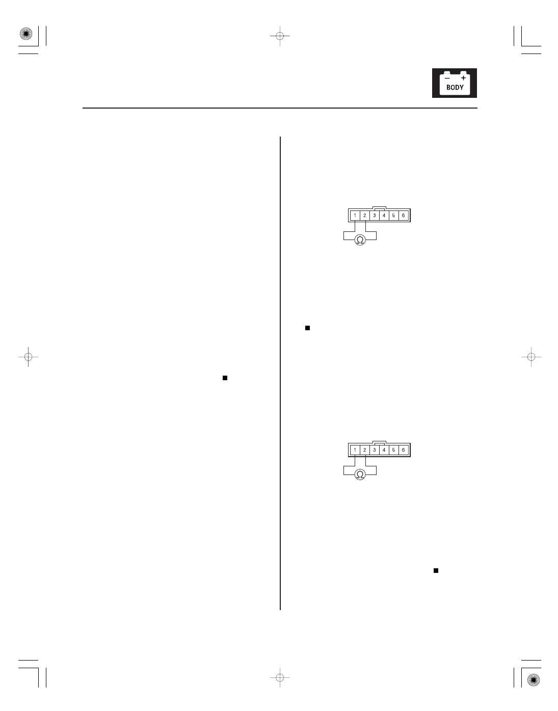
IGNITION KEY SWITCH 6P CONNECTOR
GND
IG KEY SW
IGNITION KEY SWITCH 6P CONNECTOR
GND
IG KEY SW
Ignition Key Switch Signal Error
NOTE:
• If you are troubleshooting multiple DTCs, be sure to
follow the instructions in B-CAN System Diagnosis
Test Mode A (see page 22-93).
• If the vehicle is equipped with an ACURA
ACCESSORY remote starter, this DTC is normal no
further diagnosis is necessary.
1. Clear the DTCs with the HDS.
2. Turn the ignition switch to LOCK (0) and remove
the ignition key.
3. Insert the ignition key into the ignition switch, and
turn the ignition switch to ON (II).
4. Check for DTCs with the HDS.
Go to step 5.
Intermittent failure, the system is OK at this
time. Check for loose or poor connections at the
immobilizer-keyless control unit 7P connector,
under-dash fuse/relay box 20P connector R, and at
the ignition key switch 6P connector.
5. Turn the ignition switch to LOCK (0) and remove
the ignition key.
6. Disconnect the ignition key switch 6P connector.
7. At the ignition key switch side, check for continuity
between ignition key switch 6P connector terminals
No. 1 and No. 2.
Faulty ignition key switch or short to ground,
replace the steering lock assembly (see page 17-14).
Go to step 8.
8. Insert the ignition key into the ignition switch.
9. At the ignition key switch side, check for continuity
between ignition key switch 6P connector terminals
No. 1 and No. 2.
Go to step 10.
Faulty ignition key switch, replace the
steering lock assembly (see page 17-14).
Terminal side of male terminals
Terminal side of male terminals
Is DT C B1925 indicated?
Is ther e continuity?
Is ther e continuity?
08/08/21 14:36:59 61SNR030_220_0321