Acura CSX. Manual - part 529
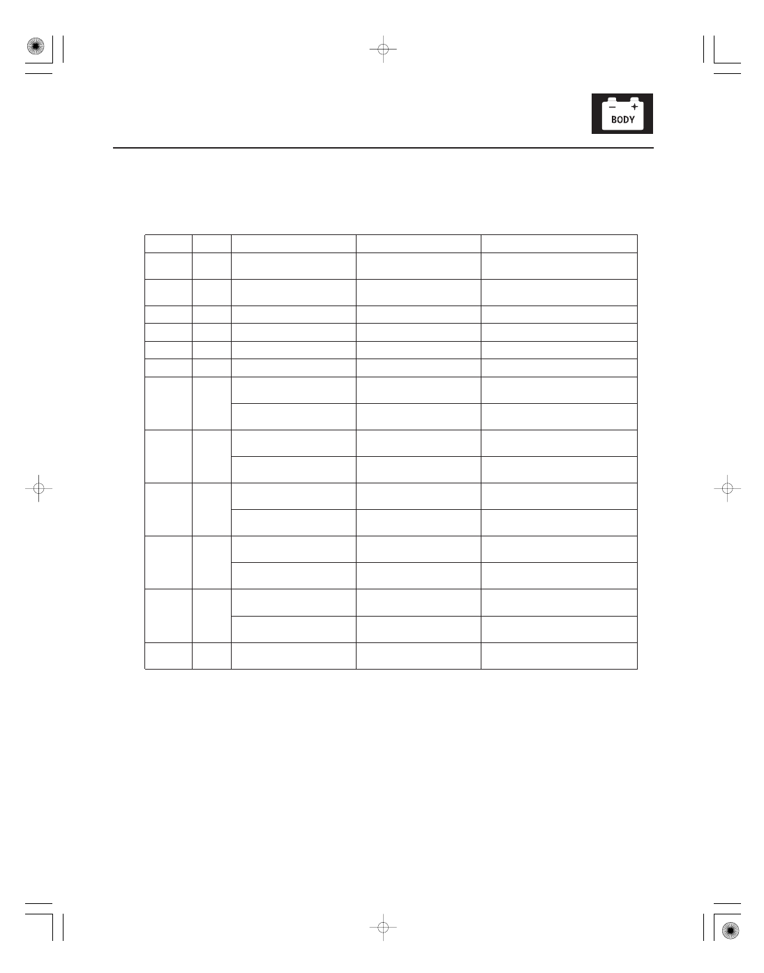
Cavity
Wire
Test condition
Test: Desired result
Possible cause if desired result is not
obtained
22-165
6. Reconnect the connectors to the under-dash fuse/relay box, and do these input tests at the following connectors.
• If any test indicates a problem, find and correct the cause, then recheck the system.
• If all the input tests prove OK, the MICU must be faulty; replace the under-dash fuse/relay box.
•
•
•
•
•
•
•
•
•
•
•
•
•
•
•
•
•
•
•
•
•
•
•
•
•
•
•
•
•
•
•
•
•
•
G2
ORN
Under all conditions
Measure the voltage between
terminal G2 and body ground:
There should be battery voltage.
Blown No. 23 (10 A) fuse in the under-
hood fuse/relay box
An open in the wire
G18
WHT
Under all conditions
Measure the voltage between
terminal G18 and body ground:
There should be battery voltage.
Blown No. 4 (50 A) fuse in the under-
hood fuse/relay box
An open in the wire
E6
BLK
Under all conditions
Measure the voltage to ground:
There should be less than 0.5 V.
Poor ground (G602)
An open in the wire
E33
BLK
Under all conditions
Measure the voltage to ground:
There should be less than 0.5 V.
Poor ground (G601)
An open in the wire
F20
BLK
Under all conditions
Measure the voltage to ground:
There should be less than 0.5 V.
Poor ground (G401)
An open in the wire
T34
BLK
Under all conditions
Measure the voltage to ground:
There should be less than 0.5 V.
Poor ground (G501)
An open in the wire
S1
·
S5
ORN
·
BLK
Combination light switch OFF
Measure the voltage between
terminals S1 and S5:
There should be less than 1 V.
Faulty combination light switch
An open in the wire
Combination light switch in any
other position than OFF
Measure the voltage between
terminals S1 and S5:
There should be more than 5 V.
Faulty combination light switch
A short to ground in the wire
S11
·
S5
PNK
·
BLK
Combination light switch
(Headlight position) ON
Measure the voltage between
terminals S11 and S5:
There should be less than 1 V.
Faulty combination light switch
An open in the wire
Combination light switch OFF
Measure the voltage between
terminals S11 and S5:
There should be more than 5 V.
Faulty combination light switch
A short to ground in the wire
S12
·
S5
RED
·
BLK
Combination light switch lever
pulled (Passing)
Measure the voltage between
terminals S12 and S5:
There should be less than 1 V.
Faulty combination light switch
An open in the wire
Combination light switch lever
released from passing position
Measure the voltage between
terminals S12 and S5:
There should be more than 5 V.
Faulty combination light switch
A short to ground in the wire
S13
·
S5
GRY
·
BLK
Combination light switch
(SMALL position) ON
Measure the voltage between
terminals S13 and S5:
There should be less than 1 V.
Faulty combination light switch
An open in the wire
Combination light switch OFF
Measure the voltage between
terminals S13 and S5:
There should be more than 5 V.
Faulty combination light switch
A short to ground in the wire
S16
·
S5
LT BLU
·
BLK
Combination light switch
(Dimmer) in high beam position
Measure the voltage between
terminals S16 and S5:
There should be less than 1 V.
Faulty combination light switch
An open in the wire
Combination light switch
(Dimmer) in low beam position
Measure the voltage between
terminals S16 and S5:
There should be more than 5 V.
Faulty combination light switch
A short to ground in the wire
C3
ORN
Ignition switch ON (II)
Measure the voltage between
terminal C3 and body ground:
There should be battery voltage.
Faulty ignition switch
An open in the wire
08/08/21 14:26:58 61SNR030_220_0167