Acura CSX. Manual - part 530


  Index      Acura     Acura CSX - P/NO. 61SNR03 - service repair manual 2006-2009 year


Search            


Content   ..  528  529  530  531   ..


Acura CSX. Manual - part 530


*01

SNR9ALBJ32133131491KBAT00

22-169

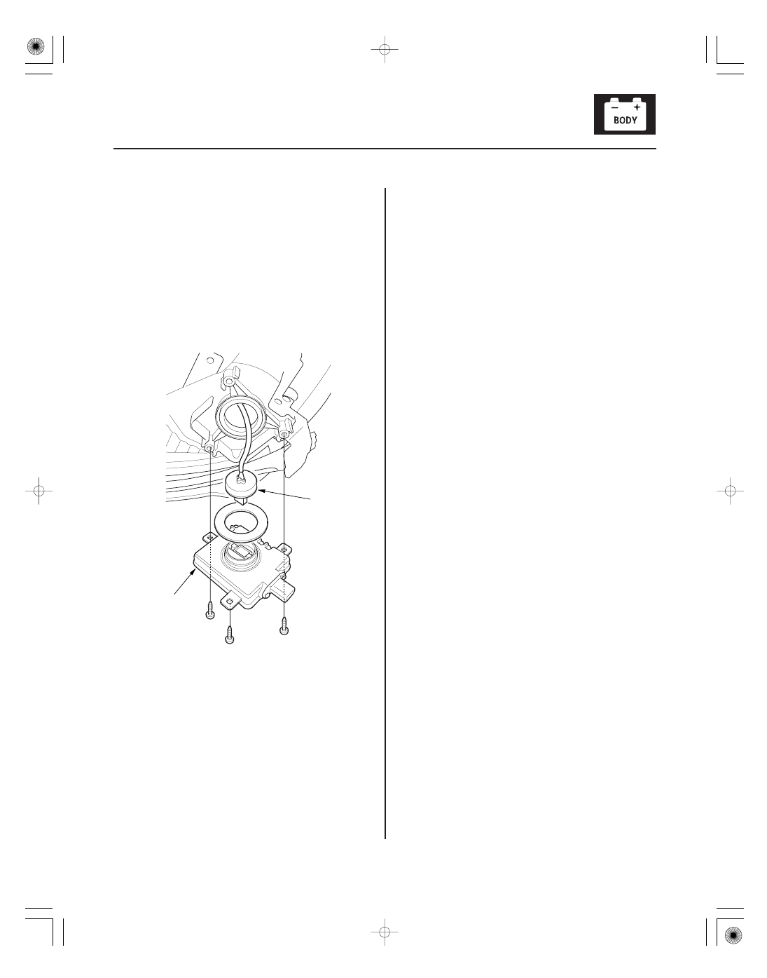
HID Unit Replacement

A

B

1. Turn the combination light switch OFF.

2. Make sure the ignition switch is in LOCK (0)

position, then do the battery terminal
disconnection procedure (see page 22-68).

3. Remove the headlight assembly (see page 22-174).

4. Remove the socket from the HID bulb (see page

22-168).

5. Remove the three mounting screws and the HID

unit (A).

6. Disconnect the 4P connector (B) from the HID unit.

7. Install the HID unit in the reverse order of removal.

8. Do the battery terminal reconnection procedure

(see page 22-68).

08/08/21 14:26:59 61SNR030_220_0171

01

SNR9ALBJ32133100000FAAT00

Special Tools Required

YES

NO

YES

NO

22-170

Exterior Lights

HID Lamp System Troubleshooting

A

B

A transient high tension (25,000 V) occurs at the
bulb sockets or the high intensity discharge (HID)
lamps when the combination light switch is turned
ON, it may cause serious electrical shock or
electrocution if you do not observe the cautions.

• Never turn on the combination light switch

before fitting the HID bulbs to their bulb sockets
and completing the reassembly of the headlight
assembly.

• Do not service the headlights assembly in wet

conditions, such as rain or snow, near a sprinkler
system, or when your hands are wet to prevent
electrocution.

• Do not touch the surface of the HID bulbs with

your bare hands and do not stain it with any oils
and fats.

• Do not disassemble the inverter unit and the

igniter unit.

• Do not turn on the HID bulb by using a power

source other than the battery mounted on your
vehicle.

HID bulb test light 07AAJ-S3MA100

NOTE: Before troubleshooting the HID Lamp System,
do the multiplex integrated control system
troubleshooting using B-CAN System Diagnosis Test
Mode A (see page 22-93).

1. Check the No. 16 (15 A), No. 17 (15 A), and No. 21

(30 A) fuses in the under-dash fuse/relay box.

Go to step 2.

Replace the fuse(s), and recheck.

2. Turn the combination light switch OFF.

3. Do the battery terminal disconnection procedure

(see page 22-68).

4. Remove the socket from the HID bulb (see page

22-168).

5. Check for corrosion (A) and traces of electrical

arcing (B) at the socket mating part.

Go to step 7.

Replace the socket, and recheck.

Ar e f uses OK ?

Is the socket cor r oded or bur nt?

08/08/21 14:27:00 61SNR030_220_0172

02

03

YES

NO

YES

NO

22-171

B

A
07AAJ-S3MA100

HID UNIT 2P CONNECTOR

BLK

6. Connect the HID bulb test light (A) to the socket (B).

7. Do the battery terminal reconnection procedure

(see page 22-68).

8. Turn the combination light (headlight) switch ON.

Replace the original HID bulb (see page

22-168).

Go to step 10.

9. Turn the combination light (headlight) switch OFF.

10. Do the battery terminal disconnection procedure

(see page 22-68).

11. Disconnect the HID bulb test light from the socket.

12. Do the battery terminal reconnection procedure

(see page 22-68).

13. Disconnect the HID unit 2P connector.

14. Turn the combination light (headlight) switch ON.

15. Check for continuity between the HID unit 2P

connector terminal No. 1 and body ground.

Go to step 16.

Repair an open in the wire between the HID

unit and body ground. If the wire is OK, check for
poor ground at G201 or G301.

Wire side of female terminals

Does the bulb in the test light come on?

Is ther e continuity?

08/08/21 14:27:00 61SNR030_220_0173

04

05

06

YES

NO

LEFT HEADLIGHT

RIGHT HEADLIGHT

YES

NO

22-172

Exterior Lights

HID UNIT 2P CONNECTOR

LEFT HEADLIGHT (PUR)
RIGHT HEADLIGHT (GRN)

HID UNIT 2P CONNECTOR (LEFT HEADLIGHT)

PUR

UNDER-DASH FUSE/RELAY BOX CONNECTOR G (21P)

UNDER-DASH FUSE/RELAY BOX CONNECTOR F (34P)

HID UNIT 2P CONNECTOR (RIGHT HEADLIGHT)

GRN

16. Measure the voltage between the HID unit 2P

connector terminal No. 2 and body ground.

Substitute a known-good HID unit, and

recheck. If the symptom/indication goes away,
replace the original HID unit.

Go to step 17.

17. Disconnect under-dash fuse/relay box connector G

(21P)

and/or F (34P) .

1: Left headlight
2: Right headlight

18. Check for continuity between under-dash fuse/relay

box G (21P) terminal No. 17 or F (34P) terminal
No. 4 and HID unit 2P connector terminal No. 2.

Replace the under-dash fuse/relay box.

Repair an open in the wire between the

under-hood fuse/relay box and the HID unit.

1

2

Wire side of female terminals

Wire side of female terminals

Wire side of female terminals

Wire side of female terminals

Wire side of female terminals

Is ther e batter y voltage?

Is ther e continuity?

08/08/21 14:27:00 61SNR030_220_0174


Content   ..  528  529  530  531   ..