Acura CSX. Manual - part 295


  Index      Acura     Acura CSX - P/NO. 61SNR03 - service repair manual 2006-2009 year


Search            


Content   ..  293  294  295  296   ..


Acura CSX. Manual - part 295


09

10

11

14-261

A

B

A

B

C

D

E

Properly Installed:

Improperly Installed:

A

B

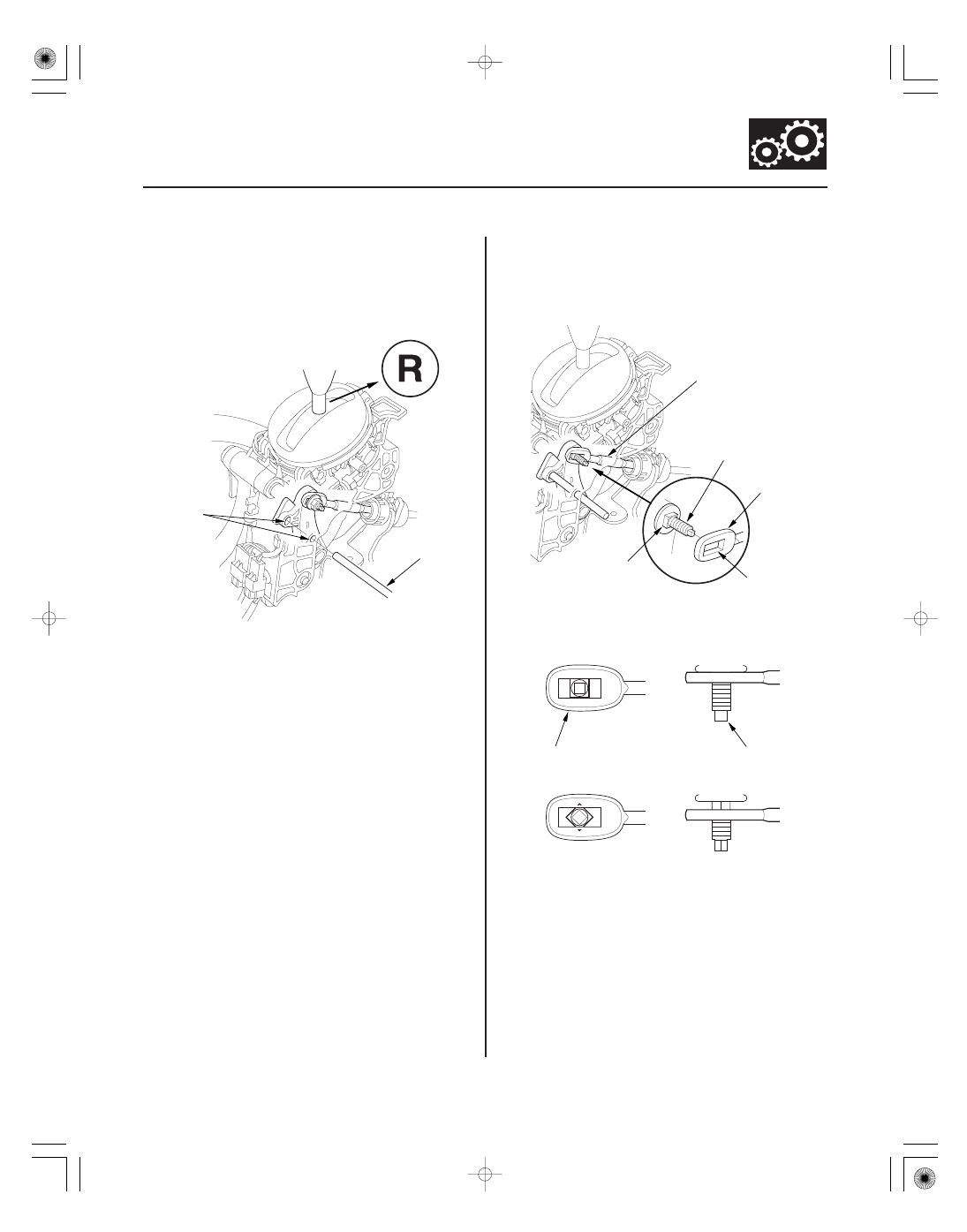
11. Place the shift lever in R, then insert a 6.0 mm

(0.24 in.) pin (A) into the positioning holes (B) on
the shift lever bracket, through the positioning hole
on the shift lever, and into the positioning hole on
the bracket. Use only a 6.0 mm pin that is free of
burrs.

12. Check that the shift lever is secured in R.

13. Install the shift cable end (A) over the mounting

stud (B) by aligning its square hole (C) with the
square fitting (D) at the bottom of the stud. Do not
install the shift cable by holding the shift cable
guide (E).

14. Check that the shift cable end (A) is properly

installed on the mounting stud (B).

15. If improperly installed, align the square fitting with

the square hole by rotating the mounting stud.

Cable end rides on the bottom of the mounting stud.

08/08/21 14:48:55 61SNR030_140_0263

12

14-262

Automatic Transmission

8 x 1.25 mm
22 N·m
(2.2 kgf·m, 16 lbf·ft)

16. Install and tighten the nut.

17. Remove the 6.0 mm (0.24 in.) pin that was installed

to hold the shift lever.

18. Turn the ignition switch to ON (II). Move the shift

lever to each position, and check that the A/T gear
position indicator follows the transmission range
switch.

19. Shift to P, and check that the shift lock works

properly. Push the shift lock release, and check that
the shift lever releases.

20. Install the center console (see page 20-92).

08/08/21 14:48:56 61SNR030_140_0264

*01

*02

SNR9AA1E10410700000DAAT00

14-263

A/T Gear Position Indicator

Component Location Index

A/T GEAR POSITION INDICATOR
SHIFT INDICATOR, M INDICATOR

A/T GEAR POSITION INDICATOR
PANEL LIGHT HARNESS

PADDLE SHIFTER
(UPSHIFT SWITCH)

PADDLE SHIFTER
(DOWNSHIFT SWITCH)

TRANSMISSION RANGE SWITCH

POWERTRAIN CONTROL
MODULE (PCM)

F-CAN Communication Circuit

Troubleshooting, page 22-265

Gauge Control Module Self-diagnostic Function
Indicator Drive Circuit Check, page 22-242
Communication Line Check, page 22-243

Replacement, page 14-269

Circuit Troubleshooting, page 14-270
Replacement, page 14-276

Circuit Troubleshooting, page 14-273
Replacement, page 14-277

Test, page 14-265
Replacement, page 14-267

08/08/21 14:48:58 61SNR030_140_0265

*01

SNR9AA1E10410700000EAAT00

14-264

A/T Gear Position Indicator

Circuit Diagram

22

36

44

43

42

27 28

30

33 34 35

32

25

20 21 22

16

18

17

13 14 15

12

11

7

8

9

3

1

31

23

31

4

5

6

15

14

21

20

25

24

34

33

29

28

27

42

44

40

37

36

31

1

2

3

4

5

6

9

8

7

11 12

15

14

13

17 18

16

32

29 30

42

43

44

40

39

36

18

17

16

19

35

9

8

10

21

20

27

2

26

29

40

4

23

24

41

23

41

10

26

39

5

6

2

1

1

2

CABLE REEL

BLU

BLU

BLU/YEL

GRN

GRN

SUPP

B16

B40

SDNP

BRN

PG1

PG2

LG1

LG2

C40

B1

C44

B36

BLK

BRN/YEL

BRN/YEL

G101

No. 14 (7. 5 A)

RED

GRY

2

1

RED/BLK

RED

PG

SG

16

15

BLK

BRN

C

(44P)

B

(44P)

A

(44P)

Terminal side of female terminals

19

1

WHT

RED

RED

WHT

17

CANL

A37

A36

CANH

1

3

8

2

7

6

4

10

1

7

5

4

9

3

8

10

BLK

B13

BLK/GRN

BRN

C36

IG1

12 V

GAUGE CONTROL MODULE (TACH)

No. 2 (15 A)

UNDER-DASH FUSE/RELAY BOX

No. 10 (7. 5 A)

BLU/WHT

RED/BLK

WHT

ORN

BAT

IG1

IGNITION SWITCH

BLK

BLU/WHT

FWD

RVS

S

ST

P

R

N

TRANSMISSION RANGE SWITCH

D

B22

ATPRVS

ATPFWD

ATPP

ATPR

ATPN

ATPD

ATPS

YEL/RED

B28

G101

B12

B21

BLU

PNK

RED/BLK

WHT

BLK/BLU

B14

B15

WHT/RED

BLU/BLK

YEL/GRN

RED

BLU/YEL

BLK

G503

D

N

R

P

UNDER-HOOD FUSE/RELAY BOX

No. 2 (IG) (50 A)

No. 1 (100 A)

BATTERY

A/T
GEAR
POSITION
INDICATOR
DRIVER
CIRCUIT

CPU

STARTER
CUT RELAY

POWERTRAIN CONTROL
MODULE (PCM)

F-CAN
TRANSCEIVER

DASH-LIGHT
BRIGHTNESS
CONTROL
CIRCUIT

A/T GEAR
POSITION
INDICATOR
PANEL LIGHT

MULTIPLEX INTEGRATED
CONTROL UNIT (MICU)

MULTIPLEX INTEGRATED
CONTROL UNIT (MICU)

SHIFT
INDICATOR

LT GRN

LEFT

BLK/WHT

LT GRN

GRN/ORN

RIGHT

PADDLE SHIFTER
(UPSHIFT SWITCH)

RED/WHT

G504

G504

5 V

BLK*

BLK/RED*

BLK

16

17

6

16

17

7

PADDLE SHIFTER
(DOWNSHIFT SWITCH)

*1: ’06 model
*2: ’07 09 models

PCM Connector Terminal Locations

S

GND

2

1

08/08/21 14:49:00 61SNR030_140_0266


Content   ..  293  294  295  296   ..