Acura CSX. Manual - part 293


  Index      Acura     Acura CSX - P/NO. 61SNR03 - service repair manual 2006-2009 year


Search            


Content   ..  291  292  293  294   ..


Acura CSX. Manual - part 293


*01

SNR9AA1E10400013012KBAT00
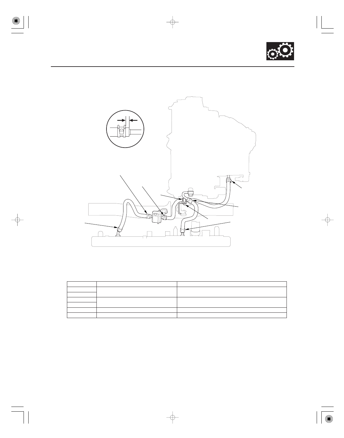
Exploded View

Point

Distance from Hose End to Clip (L)

Hose End Contact Point

14-253

ATF Cooler Hose Replacement

L

G

H

E
White paint mark

A
Pink paint mark

B
Pink paint mark

C
White paint mark

D
Pink paint mark

F
White paint mark

NOTE: When installing the hose clamps, make sure not to interfere to the surrounding parts.

1. Install the ATF cooler hoses over the ATF cooler lines with the clips at appropriate points in reference to the

following list.

A

6

8 mm (0.24

0.31 in.)

Bulge

B
C

5

7 mm (0.20

0.28 in.)

ATF filter from 10

12 mm (0.40

0.47 in.)

D

E

2

4 mm (0.08

0.16 in.)

White paint line

F

2

4 mm (0.08

0.16 in.)

Bulge

2. Secure the ATF cooler hose with the clamp (G) at the white paint line (H).

3. Refill the transmission with ATF to the proper level (see page 14-232).

08/08/21 14:48:50 61SNR030_140_0255

01

02

03

04

SNR9AA1E10411412282KAAT00

14-254

Automatic Transmission

Shift Lever Removal

A

A

B

C

A

B

1. Remove the center console (see page 20-92).

2. Move the shift lever to R.

3. Pry the socket holder lock (A) up using a

screwdriver.

4. Remove the nut securing the shift cable end.

5. Rotate the socket holder retainer (A)

counterclockwise, push it against the socket holder
bracket (B), then slide the socket holder to remove
the shift cable (C) from the socket holder bracket.

6. Disconnect the shift lock solenoid connector (A)

and the park pin switch/A/T gear position indicator
panel light connector (B).

7. Remove the shift lever assembly.

08/08/21 14:48:51 61SNR030_140_0256

*01

SNR9AA1E10411412282KCAT00

14-255

Shift Lever Installation

B

C

8 x 1.25 mm
22 N·m
(2.2 kgf·m, 16 lbf·ft)

A

1. Install the shift lever assembly (A).

2. Connect the shift lock solenoid connector (B) and

the park pin switch/A/T gear position indicator
panel light connector (C).

3. Install the shift cable on the shift lever, and adjust

the cable (see step 5 on page 14-259).

08/08/21 14:48:51 61SNR030_140_0257

*01

SNR9AA1E10411412282MFAT10

14-256

Automatic Transmission

Shift Lever Disassembly/Reassembly

A/T GEAR POSITION
INDICATOR PANEL

SCREWS
3 N·m
(0.3 kgf·m, 2 lbf·ft)

SHIFT LEVER KNOB

SILICONE GREASE

SHIFT LOCK SOLENOID

HARNESS CLAMP

PARK PIN SWITCH/
A/T GEAR POSITION
INDICATOR PANEL
LIGHT CONNECTOR

PARK PIN SWITCH

SHIFT LOCK RELEASE SPRING

SHIFT LOCK
SOLENOID PLUNGER

SHIFT LOCK STOP CUSHION

SHIFT LOCK
STOP

SHIFT LEVER
ASSEMBLY/
BRACKET BASE

SHIFT LEVER
ROD

LEVER COVER

A/T GEAR POSITION
INDICATOR PANEL
LIGHT BLUB

SHIFT LOCK
RELEASE

SHIFT LEVER SHROUD

PLUNGER SPRING

SILICONE
GREASE

SHIFT LOCK
SOLENOID CONNECTOR

BUSHING

SHIFT LEVER ROD CAP

SILICONE GREASE

SILICONE GREASE

NOTE: Make sure not to get any silicone grease on the terminal part of the connectors and switches, especially if you
have silicone grease on your hands or gloves.

Replace.

08/08/21 14:48:52 61SNR030_140_0258


Content   ..  291  292  293  294   ..