Acura CSX. Manual - part 296


  Index      Acura     Acura CSX - P/NO. 61SNR03 - service repair manual 2006-2009 year


Search            


Content   ..  294  295  296  297   ..


Acura CSX. Manual - part 296


01

*01

03

SNR9AA1E10410759811FEAT00

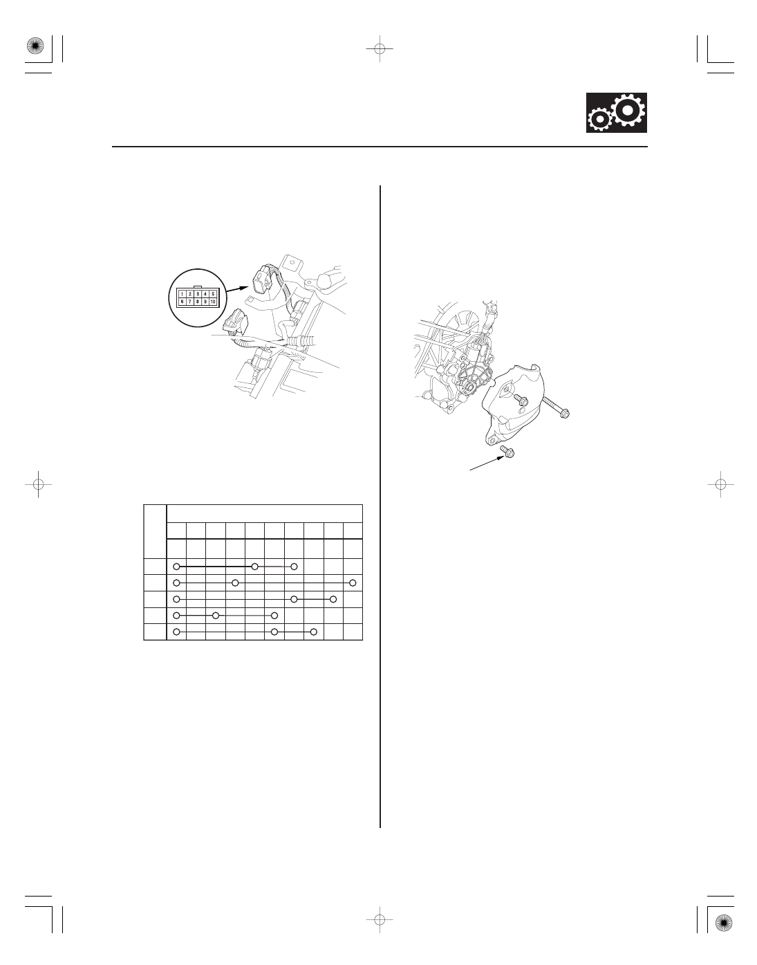
Transmission Range Switch Subharness
Connector

14-265

Transmission Range Switch Test

A

Connector Terminal/Signal

2

5

1

3

4

6

8

7

9

10

P

R

N

D

S

Posi-
tion

6 x 1.0 mm
12 N·m (1.2 kgf·m, 8.7 lbf·ft)

ATP
NP

ATP
FWD

GND

ATP
RVS

ATP
D

ATP
R

ATP
P

ATP
S

ATP
N

1. Remove the intake air duct (see page 11-348) and

the air cleaner assembly (see page 11-345).

2. Disconnect the transmission range switch

subharness connector (A).

3. Check for continuity between the terminals at the

harness connector. There should be continuity
between the terminals in the following table for
each switch position.

4. Transmission range switch test has completed if

the test results are OK, go to step 12. If there is no
continuity between any terminals, go to step 5.

5. Raise the vehicle on a lift, or apply the parking

brake, block the rear wheels, and raise the front of
the vehicle. Make sure it is securely supported.

6. Remove the transmission range switch cover.

Terminal side of
male terminals

08/08/21 14:49:01 61SNR030_140_0267

04

*02

06

Transmission Range Switch Connector

Selector Control Shaft:
Width (B):

6.1

6.2 mm (0.240

0.244 in.)

End Gap (C): 1.8

2.0 mm (0.07

0.08 in.)

14-266

A/T Gear Position Indicator

Connector Terminal/Signal

2

5

1

3

4

6

8

7

9

10

P

R

N

D

S

Posi-
tion

A

C

B

ATP
NP

ATP
FWD

GND

ATP
RVS

ATP
N

ATP
S

ATP
P

ATP
R

ATP
D

7. Disconnect the transmission range switch

connector.

8. Check for continuity between the terminals at the

switch connector. There should be continuity
between the terminals in the following table for
each switch position.

9. If the transmission range switch test is OK, replace

the faulty transmission range switch harness, then
go to step 12. If there is no continuity between any
terminals, go to step 10.

10. Remove the transmission range switch, and check

the end of the selector control shaft (A).

11. If the measurement at the end of the selector

control shaft is within the standard, replace the
transmission range switch. If the measurement is
out of the standard, repair the selector control shaft
end, and recheck the transmission range switch
continuity.

12. Check the connector for rust, dirt, or oil, clean or

repair if necessary, then connect the connector
securely.

13. Install the removed parts in the reverse order of

removal.

08/08/21 14:49:01 61SNR030_140_0268

01

02

*01

04

SNR9AA1E10410759811KBAT00

14-267

Transmission Range Switch Replacement

A

B

C

D

1. Raise the vehicle on a lift, or apply the parking

brake, block the rear wheels, and raise the front of
the vehicle. Make sure it is securely supported.

2. Move the shift lever to N.

3. Remove the transmission range switch cover.

4. Remove the transmission range switch.

5. Make sure the control shaft is in the N position. If

necessary, move the shift lever to N from P.

NOTE: Do not use the selector control shaft to
adjust the shift position. If the control shaft tips are
squeezed together it will cause a faulty signal or
position due to play between the selector control
shaft and the transmission range switch.

6. Align the cutouts (A) on the rotary-frame with the

neutral positioning cutouts (B) on the transmission
range switch (C), then put a 2.0 mm (0.08 in.) feeler
gauge blade (D) in the cutouts to hold the switch in
the N position.

NOTE: Be sure to use a 2.0 mm (0.08 in.) blade or
equivalent to hold the switch in the N position.

08/08/21 14:49:02 61SNR030_140_0269

05

06

07

14-268

A/T Gear Position Indicator

A

C

B

6 x 1.0 mm
12 N·m (1.2 kgf·m, 8.7 lbf·ft)

6 x 1.0 mm
12 N·m (1.2 kgf·m, 8.7 lbf·ft)

A

7. Install the transmission range switch (A) gently on

the selector control shaft (B) while holding it in the
N position with the 2.0 mm (0.08 in.) blade (C).

8. Tighten the bolts on the transmission range switch

while you continue to holding the N position. Do
not move the transmission range switch when
tightening the bolts. Remove the feeler gauge.

9. Check the connectors for rust, dirt, or oil, clean or

repair if necessary, then connect the connector
securely.

10. Turn the ignition switch to ON (II). Move the shift

lever through all positions, and check the
transmission range switch synchronization with the
A/T gear position indicator.

11. Check that the engine will start with the shift lever

in P and N, and will not start in any other shift lever
position.

12. Check that the back-up lights come on when the

shift lever is in R.

13. Allow the front wheels to rotate freely, then start

the engine, and check the shift lever operation.

14. Install the transmission range switch cover (A).

08/08/21 14:49:03 61SNR030_140_0270


Content   ..  294  295  296  297   ..