Kia Sedona (2008 year). Manual - part 423


  Главная      Kia     Kia Sedona (2008 year) - Service Repair Manual


поиск по сайту           правообладателям


содержание   ..  421  422  423  424   ..


Kia Sedona (2008 year). Manual - part 423
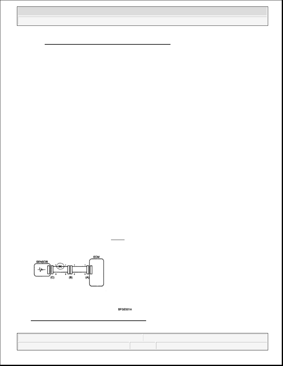


Fig. 8: Pulling On Each Wire In Connector Terminal
Courtesy of KIA MOTORS AMERICA, INC.
 

3. Repair Method of Connector Terminal 

a. Clean the contact points using air gun and/or shop rag. 

b. In case of abnormal contact pressure, replace the female terminal.  

WIRE HARNESS INSPECTION PROCEDURE 

1. Before removing the wire harness, check the wire harness position and crimping in order to restore it 

correctly.  

2. Check whether the wire harness is twisted, pulled or loosened.  

3. Check whether the temperature of the wire harness is abnormally high.  

4. Check whether the wire harness is rotating, moving or vibrating against the sharp edge of a part.  

5. Check the connection between the wire harness and any installed part.  

6. If the covering of wire harness is damaged; secure, repair or replace the harness.  

ELECTRICAL CIRCUIT INSPECTION PROCEDURE 

• CHECK OPEN CIRCUIT  

1. Procedures for Open Circuit 

Continuity Check  

Voltage Check  

If an open circuit occurs (as seen in Fig. 9), it can be found by performing Step 2 (Continuity Check 
Method) or Step 3 (Voltage Check Method). 

Fig. 9: Voltage Check Method - Circuit Diagram 
Courtesy of KIA MOTORS AMERICA, INC.

NOTE:

Never use sand paper when polishing the contact points, otherwise 
the contact point may be damaged.


2008 Kia Sedona 

2008 ENGINE PERFORMANCE Fuel System - General - Sedona


Microsoft 


Saturday, May 22, 2010 3:59:43 PM

Page 17 

© 2006 Mitchell Repair Information Company, LLC. 

2. Continuity Check Method 

Specification (Resistance) 

1ohms or less --> Normal Circuit 

1ohms or Higher --> Open Circuit 

a. Disconnect connectors (A), (C) and measure resistance between connector (A) and (C) as shown in 

Fig. 10

In Fig. 10 the measured resistance of line 1 and 2 is higher than 1MQ and below 1Q respectively. 
Specifically the open circuit is line 1 (Line 2 is normal). To find exact break point, check sub line 
of line 1 as described in next step. 

Fig. 10: Resistance Check Method - Circuit Diagram 
Courtesy of KIA MOTORS AMERICA, INC. 

b. Disconnect connector (B), and measure for resistance between connector (C) and (B1) and between 

(B2) and (A) as shown in Fig. 11

In this case the measured resistance between connector (C) and (B1) is higher than 1MQ and the 
open circuit is between terminal 1 of connector (C) and terminal 1 of connector (B1).

NOTE:

When measuring for resistance, lightly shake the wire harness above and 
below or from side to side.


2008 Kia Sedona 

2008 ENGINE PERFORMANCE Fuel System - General - Sedona


Microsoft 


Saturday, May 22, 2010 3:59:43 PM

Page 18 

© 2006 Mitchell Repair Information Company, LLC. 

Fig. 11: Resistance Check Method - Circuit Diagram 
Courtesy of KIA MOTORS AMERICA, INC. 

3. Voltage Check Method 

a. With each connector still connected, measure the voltage between the chassis ground and terminal 

1 of each connectors (A), (B) and (C) as shown in Fig. 12

The measured voltage of each connector is 5V, 5V and 0V respectively. So the open circuit is 
between connector (C) and (B). 

Fig. 12: Voltage Check Method - Circuit Diagram 
Courtesy of KIA MOTORS AMERICA, INC. 

• CHECK SHORT CIRCUIT  

1. Test Method for Short to Ground Circuit 

Continuity Check with Chassis Ground  

If short to ground circuit occurs as shown in Fig. 13, the broken point can be found by performing Step 2 
(Continuity Check Method with Chassis Ground).


2008 Kia Sedona 

2008 ENGINE PERFORMANCE Fuel System - General - Sedona


Microsoft 


Saturday, May 22, 2010 3:59:43 PM

Page 19 

© 2006 Mitchell Repair Information Company, LLC. 

Fig. 13: Continuity Check Method - Circuit Diagram 
Courtesy of KIA MOTORS AMERICA, INC. 

2. Continuity Check Method (with Chassis Ground) 

Specification (Resistance) 

1ohms or less --> Short to Ground Circuit 

1M ohms or Higher --> Normal Circuit 

a. Disconnect connectors (A), (C) and measure for resistance between connector (A) and Chassis 

Ground as shown in Fig. 14

The measured resistance of line 1 and 2 in this example is below 1Q and higher than 1MB 
respectively. Specifically the short to ground circuit is line 1 (Line 2 is normal). To find exact 
broken point, check the sub line of line 1 as described in the following step. 

Fig. 14: Resistance Check Method - Circuit Diagram 
Courtesy of KIA MOTORS AMERICA, INC.

NOTE:

Lightly shake the wire harness above and below, or from side to side when 
measuring the resistance.


2008 Kia Sedona 

2008 ENGINE PERFORMANCE Fuel System - General - Sedona


Microsoft 


Saturday, May 22, 2010 3:59:43 PM

Page 20 

© 2006 Mitchell Repair Information Company, LLC. 


содержание   ..  421  422  423  424   ..