Intel 64 and IA-32 Architectures. Software Developer’s Manual (Collection, 2023) - page 136
Intel® Architecture
Instruction Set Extensions
and Future Features
Programming Reference
September 2023
319433-050
Revision History
Revision
Description
Date
•
Removed instructions that now reside in the Intel® 64 and IA-32
Architectures Software Developer’s Manual.
•
Minor updates to chapter 1.
•
Updates to Table 2-1, Table 2-2 and Table 2-8 (leaf 07H) to indicate
support for AVX512_4VNNIW and AVX512_4FMAPS.
-025
•
Minor update to Table 2-8 (leaf 15H) regarding ECX definition.
September 2016
•
Minor updates to Section 4.6.2 and Section 4.6.3 to clarify the effects of
“suppress all exceptions”.
•
Footnote addition to CLWB instruction indicating operand encoding
requirement.
•
Removed PCOMMIT.
•
Removed CLWB instruction; it now resides in the Intel® 64 and IA-32
-026
Architectures Software Developer’s Manual.
October 2016
•
Added additional 512-bit instruction extensions in chapter 6.
•
Added TLB CPUID leaf in chapter 2.
-027
•
Added VPOPCNTD/Q instruction in chapter 6,and CPUID details in
December 2016
chapter 2.
-028
•
Updated intrinsics for VPOPCNTD/Q instruction in chapter 6.
December 2016
•
Corrected typo in CPUID leaf 18H.
•
Updated operand encoding table format; extracted tuple information
from operand encoding.
-029
April 2017
•
Added VPERMB back into chapter 5; inadvertently removed.
•
Moved all instructions from chapter 6 to chapter 5.
•
Updated operation section of VPMULTISHIFTQB.
•
Removed unnecessary information from document (chapters 2, 3 and 4).
•
Added table listing recent instruction set extensions introduction in Intel
64 and IA-32 Processors.
•
Updated CPUID instruction with additional details.
•
Added the following instructions: GF2P8AFFINEINVQB, GF2P8AFFINEQB,
GF2P8MULB, VAESDEC, VAESDECLAST, VAESENC, VAESENCLAST,
VPCLMULQDQ, VPCOMPRESS, VPDPBUSD, VPDPBUSDS, VPDPWSSD,
VPDPWSSDS, VPEXPAND, VPOPCNT, VPSHLD, VPSHLDV, VPSHRD,
-030
VPSHRDV, VPSHUFBITQMB.
October 2017
•
Removed the following instructions: VPMADD52HUQ, VPMADD52LUQ,
VPERMB, VPERMI2B, VPERMT2B, and VPMULTISHIFTQB. They can be
found in the Intel® 64 and IA-32 Architectures Software Developer’s
Manual, Volumes 2A, 2B, 2C, & 2D.
•
Moved instructions unique to processors based on the Knights Mill
microarchitecture to chapter 3.
•
Added chapter 4: EPT-Based Sub-Page Permissions.
•
Added chapter 5: Intel® Processor Trace: VMX Improvements.
Document Number: 319433-050
iii
Revision
Description
Date
•
Updated change log to correct typo in changes from previous release.
•
Updated instructions with imm8 operand missing in operand encoding
table.
•
Replaced “VLMAX” with “MAXVL” to align terminology used across
documentation.
•
Added back information on detection of Intel AVX-512 instructions.
•
Added Intel® Memory Encryption Technologies instructions PCONFIG and
WBNOINVD. These instructions are also added to Table 1-1 “Recent
Instruction Set Extensions Introduction in Intel 64 and IA-32 Processors”.
Added Section 1.5 “Detection of Intel® Memory Encryption Technologies
(Intel® MKTME) Instructions”.
-031
January 2018
•
CPUID instruction updated with PCONFIG and WBNOINVD details.
•
CPUID instruction updated with additional details on leaf 07H: Intel®
Xeon Phi™ only features identified and listed.
•
CPUID instruction updated with new Intel® SGX features in leaf 12H.
•
CPUID instruction updated with new PCONFIG information sub-leaf 1BH.
•
Updated short descriptions in the following instructions: VPDPBUSD,
VPDPBUSDS, VPDPWSSD and VPDPWSSDS.
•
Corrections and clarifications in Chapter 4 “EPT-Based Sub-Page
Permissions”.
•
Corrections and clarifications in Chapter 5 “Intel® Processor Trace: VMX
Improvements”.
•
Corrected PCONFIG CPUID feature flag on instruction page.
•
Minor updates to PCONFIG instruction pages: Changed Table 2-2 to use
-032
Hex notation; changed “RSVD, MBZ” to “Reserved, must be zero” in two
January 2018
places in Table 2-3.
•
Minor typo correction in WBNOINVD instruction description.
•
Updated Table 1-2 “Recent Instruction Set Extensions / Features
Introduction in Intel® 64 and IA-32 Processors” .
•
Added Section 1.4, “Detection of Future Instructions and Features”.
•
Added CLDEMOTE, MOVDIRI, MOVDIR64B, TPAUSE, UMONITOR and
UMWAIT instructions.
•
Updated the CPUID instruction with details on new instructions/features
added, as well as new power management details and information on
-033
March 2018
hardware feedback interface ISA extensions.
•
Corrections to PCONFIG instruction.
•
Moved instructions unique to processors based on the Knights Mill
microarchitecture to the Intel® 64 and IA-32 Architectures Software
Developer’s Manual.
•
Added Chapter 5 “Hardware Feedback Interface ISA Extensions”.
•
Added Chapter 6 “AC Split Lock Detection”.
•
Added clarification to leaf 07H in the CPUID instruction.
•
Added MSR index for IA32_UMWAIT_CONTROL MSR.
-034
May 2018
•
Updated registers in TPAUSE and UMWAIT instructions.
•
Updated TPAUSE and UMWAIT intrinsics.
iv
Document Number: 319433-050
Revision
Description
Date
•
Updated Table 1-2 “Recent Instruction Set Extensions / Features
Introduction in Intel® 64 and IA-32 Processors” to list the AVX512_VNNI
instruction set architecture on a separate line due to presence on future
processors available sooner than previously listed.
•
Updated CPUID instruction in various places.
•
Removal of NDD/DDS/NDS terms from instructions. Note: Previously, the
terms NDS, NDD and DDS were used in instructions with an EVEX (or
VEX) prefix. These terms indicated that the vvvv field was valid for
encoding, and specified register usage. These terms are no longer
necessary and are redundant with the instruction operand encoding
tables provided with each instruction. The instruction operand encoding
tables give explicit details on all operands, indicating where every
-035
October 2018
operand is stored and if they are read or written. If vvvv is not listed as
an operand in the instruction operand encoding table, then EVEX (or
VEX) vvvv must be 0b1111.
•
Added additional #GP exception condition to TPAUSE and UMWAIT.
•
Updated Chapter 5 “Hardware Feedback Interface ISA Extensions” as
follows: changed scheduler/software to operating system or OS, changed
LP0 Scheduler Feedback to LP0 Capability Values, various description
updates, clarified that capability updates are independent, and added an
update to clarify that bits 0 and 1 will always be set together in Section
5.1.4.
•
Added IA32_CORE_CAPABILITY MSR to Chapter 6 “AC Split Lock
Detection”.
•
Added AVX512_BF16 instructions in chapter 2; related CPUID
information updated in chapter 1.
•
Added new section to chapter 1 describing bfloat16 format.
•
CPUID leaf updates to align with the Intel® 64 and IA-32 Architectures
Software Developer’s Manual.
-036
April 2019
•
Removed CLDEMOTE, TPAUSE, UMONITOR, and UMWAIT instructions;
they now reside in the Intel® 64 and IA-32 Architectures Software
Developer’s Manual.
•
Changes now marked by green change bars and green font in order to
view changes at a text level.
•
Removed chapter 3, “EPT-Based Sub-Page Permissions”, chapter 4,
“Intel® Processor Trace: VMX Improvements”, and chapter 6, “Split Lock
Detection”; this information is in the Intel® 64 and IA-32 Architectures
Software Developer’s Manual.
•
Removed MOVDIRI and MOVDIR64B instructions; they now reside in the
Intel® 64 and IA-32 Architectures Software Developer’s Manual.
-037
May 2019
•
Updated Table 1-2 with new features in future processors.
•
Updated Table 1-3 with support for AVX512_VP2INTERSECT.
•
Updated Table 1-5 with support for ENQCMD: Enqueue Stores.
•
Added ENQCMD/ENQCMDS and VP2INTERSECTD/VP2INTERSECTQ
instructions, and updated CPUID accordingly.
•
Added new chapter: Chapter 4, UC-Lock Disable.
Document Number: 319433-050
v
Revision
Description
Date
•
Removed instruction extensions/features from Table 1-2 “Recent
Instruction Set Extensions / Features Introduction in Intel® 64 and IA-32
Processors” that are available in processors covered in the Intel® 64 and
IA-32 Architectures Software Developer’s Manual. This information can
be found in Chapter 5 “Instruction Set Summary”, of Volume 1.
•
In Section 1.7, “Detection of Future Instructions”, removed instructions
from Table 1-5 “Future Instructions” that are available in processors
covered in the Intel® 64 and IA-32 Architectures Software Developer’s
Manual.
•
Removed instructions with the following CPUID feature flags:
AVX512_VNNI, VAES, GFNI (AVX/AVX512), AVX512_VBMI2,
VPCLMULQDQ, AVX512_BITALG; they now reside in the Intel® 64 and
IA-32 Architectures Software Developer’s Manual.
•
CPUID instruction updated with Hybrid information sub-leaf 1AH,
-038
SERIALIZE and TSXLDTRK support, updates to the L3 Cache Intel RDT
March 2020
Monitoring Capability Enumeration Sub-leaf, and updates to the Memory
Bandwidth Allocation Enumeration Sub-leaf.
•
Replaced ← with := notation in operation sections of instructions. These
changes are not marked with change bars.
•
Added the following instructions: SERIALIZE, XRESLDTRK, XSUSLDTRK.
•
Update to the VDPBF16PS instruction.
•
Updates to Chapter 4, “Hardware Feedback Interface ISA Extensions”.
•
Added Chapter 5, “TSX Suspend Load Address Tracking”.
•
Added Chapter 6, “Hypervisor-managed Linear Address Translation”.
•
Added Chapter 7, “Architectural Last Branch Records (LBRs)”.
•
Added Chapter 8, “Non-Write-Back Lock Disable Architecture”.
•
Added Chapter 9, “Intel® Resource Director Technology Feature
Updates”.
•
Updated Section 1.1 “About this Document” to reflect chapter changes in
this release.
•
Added Section 1.2 “DisplayFamily and DisplayModel for Future
Processors”.
•
Updated Table 1-2 “Recent Instruction Set Extensions / Features
Introduction in Intel® 64 and IA-32 Processors”.
•
CPUID instruction updated.
-039
June 2020
•
Removed Chapter 4 “Hardware Feedback Interface”. This information is
now in the Intel® 64 and IA-32 Architectures Software Developer’s
Manual.
•
Updated Figure 5-1 “Example HLAT Software Usage”.
•
Added Table 6-5 “Encodings for 64-Bit Guest-State Fields
(0010_10xx_xxxx_xxxAb)” to Chapter 6.
•
Added Chapter 8 “Bus Lock and VM Notify”.
•
Updated Section 1.1 “About this Document” to reflect chapter changes in
this release.
•
Updated Table 1-2 “Recent Instruction Set Extensions / Features
Introduction in Intel® 64 and IA-32 Processors”.
•
CPUID instruction updated.
-040
June 2020
•
Added notation updates to the beginning of Chapter 2. Updated ENQCMD
and ENQCMDS instructions to use this notation.
•
Added Chapter 3, “Intel® AMX Instruction Set Reference, A-Z”.
•
Minor updates to Chapter 6, “Hypervisor-managed Linear Address
Translation”.
vi
Document Number: 319433-050
Revision
Description
Date
•
Updated Section 1.1 “About this Document” to reflect chapter changes in
this release.
•
Updated Table 1-2 “Recent Instruction Set Extensions / Features
Introduction in Intel® 64 and IA-32 Processors”.
•
CPUID instruction updated for enumeration of several new features.
•
PCONFIG instruction updated.
•
Added CLUI, HRESET, SENDUIPI, STUI, TESTUI, UIRET, VPDPBUSD,
VPDPBUSDS, VPDPWSSD, and VPDPWSSDS instructions to Chapter 2.
-041
October 2020
•
Updated Figure 3-2, “The TMUL Unit”.
•
Update to pseudocode of TILELOADD/TILELOADDT1 instruction.
•
Addition to Section 6.2, “VMCS Changes”.
•
Update to Section 7.1.2.4, “Call-Stack Mode”.
•
Update to Section 9.1 “Bus Lock Debug Exception”.
•
Added Chapter 11, “User Interrupts”.
•
Added Chapter 12, “Performance Monitoring Updates”.
•
Added Chapter 13, “Enhanced Hardware Feedback Interface”.
•
CPUID instruction updated.
•
Removed the following instructions: VCVTNE2PS2BF16,
VCVTNEPS2BF16, VDPBF16PS, VP2INTERSECTD/VP2INTERSECTQ, and
WBNOINVD. They can be found in the Intel® 64 and IA-32 Architectures
Software Developer’s Manual, Volume 2C.
•
Updated bit positions in Section 6.12, “Changes to VMX Capability
Reporting”.
-042
December 2020
•
Typo correction in Chapter 8, “Non-Write-Back Lock Disable
Architecture”.
•
Several updates to Chapter 13, “Enhanced Hardware Feedback Interface
(EHFI)”.
•
Added Chapter 14, “Linear Address Masking (LAM)”.
•
Added Chapter 15, “Error Codes for Processors Based on Sapphire Rapids
Microarchitecture”.
•
Updated CPUID instruction.
•
Typo correction in Table 8-2, “TEST_CTRL MSR”.
-043
February 2021
•
Typo corrections in Section 14.1, “Enumeration, Enabling, and
Configuration”.
•
Updated Table 1-2, “Recent Instruction Set Extensions / Features
Introduction in Intel® 64 and IA-32 Processors”.
•
Updated CPUID instruction.
•
Updates to the ENQCMD and ENQCMDS instructions.
•
Removed the PCONFIG instruction; it can be found in the Intel® 64 and
IA-32 Architectures Software Developer’s Manual, Volume 2B.
-044
•
Corrected typo in the VPDPBUSD instruction.
May 2021
•
Updates to Table 3-1, “Intel® AMX Exception Classes “.
•
Change in terminology updates in Chapter 7, “Architectural Last Branch
Records (LBRs)”.
•
Updated Chapter 6 to introduce the official technology name: Intel®
Virtualization Technology - Redirect Protection.
•
Added Chapter 16, “IPI Virtualization”.
Document Number: 319433-050
vii
Revision
Description
Date
•
Chapter 1: Updated the CPUID instruction.
•
Chapter 2: Updated ENQCMD and ENQCMDS to remove statements that
these instructions ignore unused bits; this is incorrect. Removed HRESET,
SERIALIZE, VPDPBUSD, VPDPBUSDS, VPDPWSSD, and VPDPWSSDS
instructions; these instructions can be found in the Intel 64 and IA-32
Architectures Software Developer’s Manual. Updates to SENDUIPI
instruction operand encoding and 64-bit mode exceptions. Update to
UIRET pseudocode.
•
Chapter 3: Updated Section 3.3., “Recommendations for System
Software”.
•
Removed Chapter 6, “Intel® Virtualization Technology: Redirect
Protection”; this information can be found in the Intel 64 and IA-32
Architectures Software Developer’s Manual.
•
Removed Chapter 7, “Architectural Last Branch Records (LBRs)”; this
information can be found in the Intel 64 and IA-32 Architectures
Software Developer’s Manual.
-045
•
Removed Chapter 12, “Performance Monitoring Updates”; this
June 2022
information can be found in the Intel 64 and IA-32 Architectures
Software Developer’s Manual.
•
Removed Chapter 13, “Enhanced Hardware Feedback Interface (EHFI)”;
this information can be found in the Intel 64 and IA-32 Architectures
Software Developer’s Manual.
•
Updated Section 7.1.1, “Bus Lock VM Exit” to provide additional clarity
and details.
•
Updated Chapter 8, “Intel® Resource Director Technology Feature
Updates” to update MBA 3.0 information.
•
Update to Section 9.5.1, “User-Interrupt Notification Identification”.
•
Minor updates to Chapter 10, “Linear Address Masking (LAM)”, to provide
additional clarity.
•
Corrected two typos in the current Table 11-1, “Intel IMC MC Error Codes
for IA32_MCi_STATUS (i= 13-20).”
•
Added Chapter 13, “Asynchronous Enclave Exit Notify and the EDECCSSA
User Leaf Function.”
•
Chapter 1: Updated Table 1-1, “CPUID Signature Values of
DisplayFamily_DisplayModel.” Updated Table 1-2, “Recent Instruction Set
Extensions / Features Introduction in Intel® 64 and IA-32 Processors.”
Updated the CPUID instruction.
•
Chapter 2: Added the following instructions: AADD, AAND, AOR, AXOR,
CMPccXADD, RDMSRLIST, VBCSTNEBF162PS, VBCSTNESH2PS,
VCVTNEEBF162PS, VCVTNEEPH2PS, VCVTNEOBF162PS,
-046
September 2022
VCVTNEOPH2PS, VCVTNEPS2BF16, VPDPB[SU,UU,SS]D[,S],
VPMADD52HUQ, VPMADD52LUQ, WRMSRLIST, and WRMSRNS.
•
Chapter 3: Added section 3.4, “Operand Restrictions,” and added the
TDPFP16PS instruction.
•
Added Chapter 14, “Code Prefetch Instruction Updates.”
•
Added Chapter 15, “Next Generation Performance Monitoring Unit
(PMU).”
viii
Document Number: 319433-050
Revision
Description
Date
•
Chapter 1: Updated Table 1-1, “CPUID Signature Values of
DisplayFamily_DisplayModel.” Updated Table 1-2, “Recent Instruction Set
Extensions / Features Introduction in Intel® 64 and IA-32 Processors.”
Updated the CPUID instruction.
•
Chapter 3: Notes added and naming updates as necessary.
•
Removed the following chapters: Chapter 4, “Enqueue Stores and
Process Address Space Identifiers (PASIDs),” Chapter 5, “Intel® TSX
Suspend Load Address Tracking,” Chapter 9, “User Interrupts,” Chapter
11, “Error Codes for Processors Based on Sapphire Rapids
Microarchitecture,” and Chapter 12, “IPI Virtualization.” This information
can be found in the Intel 64 and IA-32 Architectures Software
Developer’s Manuals.
•
Removed the following instructions: CLUI, ENQCMD, ENQCMDS,
-047
LDTILECFG, SENDUIPI, STTILECFG, STUI, TDPBF16PS,
December 2022
TDPBSSD/TDPBSUD/TDPBUSD/TDPBUUD, TESTUI,
TILELOADD/TILELOADDT1, TILERELEASE, TILESTORED, TILEZERO,
UIRET, XRESLDTRK, and XSUSLDTRK. These instructions can be found in
the Intel 64 and IA-32 Architectures Software Developer’s Manuals.
•
Chapter 4: Updates to MSR name and description of bits.
•
Chapter 6: Updates to information, including naming changes and typo
corrections as necessary.
•
Chapter 10: Update to the description of the Retire Latency field given in
Section 10.3.1, “Timed Processor Event Based Sampling.”
•
Added Chapter 11, “Linear Address Space Separation (LASS).”
•
Added Chapter 12, “Virtualization of the IA32_SPEC_CTRL MSR.”
•
Added Chapter 13, “Remote Atomic Operations in Intel Architecture.”
•
Chapter 1: Updated Table 1-2, “Recent Instruction Set Extensions /
Features Introduction in Intel® 64 and IA-32 Processors.” Updated the
CPUID instruction.
•
Chapter 3: Added the TCMMIMFP16PS/TCMMRLFP16PS instructions.
•
Chapter 4: The majority of the chapter was updated to describe the UC-
lock disable feature.
•
Chapter 8: Significant updates throughout the chapter. Added new
-048
Section 8.3.2, “Counters Snapshotting,” new Section 8.4, “LBR
March 2023
Enhancements,” and new Section 8.5, “PerfMon MSRs Aliasing.”
•
Removal of chapters: Removed previous Chapter 4, “Non-Write-Back
Lock Disable Architecture.” Removed previous Chapter 5, “Bus Lock and
VM Notify.” Removed previous Chapter 8, “Asynchronous Enclave Exit
Notify and the EDECCSSA User Leaf Function.” The information from
these chapters can be found in the Intel 64 and IA-32 Architectures
Software Developer’s Manuals.
Document Number: 319433-050
ix
Revision
Description
Date
•
Chapter 1: Updated Table 1-1, “Signature Values of
DisplayFamily_DisplayModel.” Updated Table 1-2, “Recent Instruction Set
Extensions / Features Introduction in Intel® 64 and IA-32 Processors.”
Updated the CPUID instruction with bits enumerating new features.
Updated the CPUID instruction to add the initial EAX value to each main
CPUID leaf name in order to accommodate new bookmarks in the final
PDF that will enable readers to jump to any main CPUID leaf of interest.
Where there are multiple initial EAX values, those values have been
tagged so they will show up underneath the main CPUID leaf name in the
final PDF.
•
Chapter 2: Added the PBNDKB, updated PCONFIG,
-049
VPDPW[SU,US,UU]D[,S], VSHA512MSG1, VSHA512MSG2,
June 2023
VSHA512RNDS2, VSM3MSG1, VSM3MSG2, VSM3RNDS2, VSM4KEY4,
and VSM4RNDS4 instructions.
•
Chapter 8: Added notes regarding the availability of the
IA32_PERF_CAPABILITIES.PEBS_FMT of 6.
•
Removed previous Chapter 10, “Virtualization of the IA32_SPEC_CTRL
MSR.” This information can be found in the Intel 64 and IA-32
Architectures Software Developer’s Manuals.
•
Added new Chapter 11, “Total Storage Encryption in Intel Architecture.”
•
Updated text changes and change bars from using the color green to use
the color violet for better accessibility for all readers.
•
Chapter 1: Updated Table 1-1, “Signature Values of
DisplayFamily_DisplayModel.” Updated Table 1-2, “Recent Instruction Set
Extensions / Features Introduction in Intel® 64 and IA-32 Processors.”
Updated the CPUID instruction with bits enumerating new features.
•
Chapter 2: Updated the CPUID feature flag for the PBNDKB instruction.
Updated the VBCSTNEBF162PS, VCVTNEEBF162PS, and
-050
VCVTNEOBF162PS instructions to remove an inaccurate statement from
September 2023
the descriptions. Updated the RDMSRLIST and WRMSRLIST instructions.
Added the URDMSR and UWRMSR instructions.
•
Chapter 5: Information on Cache Bandwidth Allocation added.
•
Chapter 8: Future performance monitoring features added, including
Auto Counter Reload (ACR).
•
Typo corrections throughout as necessary.
x
Document Number: 319433-050
REVISION HISTORY
CHAPTER 1
FUTURE INTEL® ARCHITECTURE INSTRUCTION EXTENSIONS AND FEATURES
1.1
About This Document
1-1
1.2
DisplayFamily and DisplayModel for Future Processors
1-1
1.3
Instruction Set Extensions and Feature Introduction in Intel® 64 and IA-32 Processors
1-2
1.4
Detection of Future Instructions and Features
1-3
1.5
CPUID Instruction
1-3
CPUID-CPU Identification
1-4
1.6
Compressed Displacement (disp8*N) Support in EVEX
1-52
1.7
bfloat16 Floating-Point Format
1-53
CHAPTER 2
INSTRUCTION SET REFERENCE, A-Z
2.1
Instruction Set Reference
2-1
AADD-Atomically Add
2-2
AAND-Atomically AND
2-4
AOR-Atomically OR
2-6
AXOR-Atomically XOR
2-8
CMPccXADD-Compare and Add if Condition is Met
2-10
PBNDKB-Platform Bind Key to Binary Large Object
2-15
PCONFIG-Platform Configuration
2-19
RDMSRLIST-Read List of Model Specific Registers
2-30
URDMSR-User Read from Model-Specific Register
2-33
UWRMSR-User Write to Model-Specific Register
2-35
VBCSTNEBF162PS-Load BF16 Element and Convert to FP32 Element With Broadcast
2-37
VBCSTNESH2PS-Load FP16 Element and Convert to FP32 Element with Broadcast
2-38
VCVTNEEBF162PS-Convert Even Elements of Packed BF16 Values to FP32 Values
2-39
VCVTNEEPH2PS-Convert Even Elements of Packed FP16 Values to FP32 Values
2-40
VCVTNEOBF162PS-Convert Odd Elements of Packed BF16 Values to FP32 Values
2-41
VCVTNEOPH2PS-Convert Odd Elements of Packed FP16 Values to FP32 Values
2-42
VCVTNEPS2BF16-Convert Packed Single-Precision Floating-Point Values to BF16 Values
2-43
VPDPB[SU,UU,SS]D[,S]-Multiply and Add Unsigned and Signed Bytes With and Without
Saturation
2-45
VPDPW[SU,US,UU]D[,S]-Multiply and Add Unsigned and Signed Words With and Without
Saturation
2-48
VPMADD52HUQ-Packed Multiply of Unsigned 52-Bit Integers and Add the High 52-Bit Products
to Qword Accumulators
2-51
VPMADD52LUQ-Packed Multiply of Unsigned 52-Bit Integers and Add the Low 52-Bit Products to
Qword Accumulators
2-52
VSHA512MSG1-Perform an Intermediate Calculation for the Next Four SHA512 Message
Qwords
2-53
VSHA512MSG2-Perform a Final Calculation for the Next Four SHA512 Message Qwords
2-54
VSHA512RNDS2-Perform Two Rounds of SHA512 Operation
2-55
VSM3MSG1-Perform Initial Calculation for the Next Four SM3 Message Words
2-57
VSM3MSG2-Perform Final Calculation for the Next Four SM3 Message Words
2-59
VSM3RNDS2-Perform Two Rounds of SM3 Operation
2-61
VSM4KEY4-Perform Four Rounds of SM4 Key Expansion
2-63
VSM4RNDS4-Performs Four Rounds of SM4 Encryption
2-65
WRMSRLIST-Write List of Model Specific Registers
2-67
WRMSRNS-Non-Serializing Write to Model Specific Register
2-70
CHAPTER 3
INTEL® AMX INSTRUCTION SET REFERENCE, A-Z
3.1
Introduction
3-1
3.1.1
Tile Architecture Details
3-3
Document Number: 319433-050
xi
3.1.2
TMUL Architecture Details
3-4
3.1.3
Handling of Tile Row and Column Limits
3-5
3.1.4
Exceptions and Interrupts
3-5
3.2
Operand Restrictions
3-5
3.3
Implementation Parameters
3-5
3.4
Helper Functions
3-6
3.5
Notation
3-7
3.6
Exception Classes
3-7
3.7
Instruction Set Reference
3-9
TCMMIMFP16PS/TCMMRLFP16PS-Matrix Multiplication of Complex Tiles Accumulated into Packed
Single Precision Tile
3-10
TDPFP16PS-Dot Product of FP16 Tiles Accumulated into Packed Single Precision Tile
3-13
CHAPTER 4
UC-LOCK DISABLE
4.1
Features to Disable Bus Locks
4-1
4.2
UC-Lock Disable
4-1
CHAPTER 5
INTEL® RESOURCE DIRECTOR TECHNOLOGY FEATURE UPDATES
5.1
Cache Bandwidth Allocation (CBA)
5-1
5.1.1
Introduction to Cache Bandwidth Allocation
5-1
5.1.2
Cache Bandwidth Allocation Enumeration
5-1
5.1.3
Cache Bandwidth Allocation Configuration
5-3
5.1.4
Cache Bandwidth Allocation Usage Considerations
5-4
CHAPTER 6
LINEAR ADDRESS MASKING (LAM)
6.1
Enumeration, Enabling, and Configuration
6-1
6.2
Treatment of Data Accesses with LAM Active for User Pointers
6-1
6.3
Treatment of Data Accesses with LAM Active for Supervisor Pointers
6-3
6.4
Canonicality Checking for Data Addresses Written to Control Registers and MSRs
6-4
6.5
Paging Interactions
6-4
6.6
VMX Interactions
6-4
6.6.1
Guest Linear Address
6-4
6.6.2
VM-Entry Checking of Values of CR3 and CR4
6-5
6.6.3
CR3-Target Values
6-5
6.6.4
Hypervisor-Managed Linear Address Translation (HLAT)
6-5
6.7
Debug and Tracing Interactions
6-5
6.7.1
Debug Registers
6-5
6.7.2
Intel® Processor Trace
6-5
6.8
Intel® SGX Interactions
6-5
6.9
System Management Mode (SMM) Interactions
6-6
CHAPTER 7
CODE PREFETCH INSTRUCTION UPDATES
PREFETCHh-Prefetch Data or Code Into Caches
7-1
CHAPTER 8
NEXT GENERATION PERFORMANCE MONITORING UNIT (PMU)
8.1
New Enumeration Architecture
8-1
8.1.1
CPUID Sub-Leafing
8-2
8.1.2
Reporting Per Logical Processor
8-2
8.1.3
General-Purpose Counters Bitmap
8-2
8.1.4
Fixed-Function Counters True-View Bitmap
8-2
8.1.5
Architectural Performance Monitoring Events Bitmap
8-3
8.1.6
Non-Architectural Performance Capabilities
8-3
xii
Document Number: 319433-050
8.2
New Architectural Events
8-3
8.2.1
Topdown Microarchitecture Analysis Level 1
8-4
8.2.1.1
Topdown Backend Bound-Event Select A4H, Umask 02H
8-4
8.2.1.2
Topdown Bad Speculation-Event Select 73H, Umask 00H
8-4
8.2.1.3
Topdown Frontend Bound-Event Select 9CH, Umask 01H
8-4
8.2.1.4
Topdown Retiring-Event Select C2H, Umask 02H
8-4
8.2.2
LBR Inserts
8-4
8.2.2.1
LBR Inserts-Event Select E4H, Umask 01H
8-4
8.3
RDPMC Enhancements
8-5
8.3.1
Metrics Clear Mode
8-5
8.4
Processor Event Based Sampling (PEBS) Enhancements
8-5
8.4.1
Timed Processor Event Based Sampling
8-5
8.4.2
Counters Snapshotting
8-5
8.4.2.1
Updated PEBS_DATA_CFG MSR
8-6
8.4.2.2
Counters and Metrics Group
8-7
8.5
Performance Monitoring MSR Enhancements
8-8
8.5.1
Performance Monitoring MSR Aliasing
8-8
8.5.2
Unit Mask 2
8-9
8.5.3
Equal Flag
8-10
8.6
LBR Enhancements
8-10
8.6.1
LBR Event Logging
8-10
8.7
Auto Counter Reload
8-11
8.7.1
Discovery and Interface
8-11
8.7.2
Configuration and Behavior
8-11
8.7.2.1
Reload Precision
8-12
8.7.2.2
PEBS Interaction
8-12
8.7.2.3
Precise Distribution (PDIST) Interaction
8-12
8.7.3
MSRs
8-13
CHAPTER 9
LINEAR ADDRESS SPACE SEPARATION (LASS)
9.1
Introduction
9-1
9.2
Enumeration and Enabling
9-1
9.3
Operation of Linear-Address Space Separation
9-1
9.3.1
Data Accesses
9-2
9.3.2
Instruction Fetches
9-2
CHAPTER 10
REMOTE ATOMIC OPERATIONS IN INTEL ARCHITECTURE
10.1
Introduction
10-1
10.2
Instructions
10-1
10.3
Alignment Requirements
10-1
10.4
Memory Ordering
10-2
10.5
Memory Type
10-2
10.6
Write Combining Behavior
10-2
10.7
Performance Expectations
10-2
10.7.1
Interaction Between RAO and Other Accesses
10-3
10.7.2
Updates of Contended Data
10-3
10.7.3
Updates of Uncontended Data
10-3
10.8
Examples
10-4
10.8.1
Histogram
10-4
10.8.2
Interrupt/Event Handler
10-4
CHAPTER 11
TOTAL STORAGE ENCRYPTION IN INTEL ARCHITECTURE
11.1
Introduction
11-1
11.1.1
Key Programming Overview
11-1
11.1.1.1
Key Wrapping Support: PBNDKB
11-1
11.1.2
Unwrapping and Hardware Key Programming Support: PCONFIG
11-1
Document Number: 319433-050
xiii
11.2
Enumeration
11-1
11.2.1
CPUID Detection
11-1
11.2.1.1
PCONFIG CPUID Leaf Extended to Support Total Storage Encryption
11-1
11.2.2
Total Storage Encryption Capability MSR
11-2
11.3
VMX Support
11-2
11.3.1
Changes to VMCS Fields
11-2
11.3.2
Changes to VMX Capability MSRs
11-2
11.3.3
Changes to VM Entry
11-2
11.4
Instruction Set
11-2
xiv
Document Number: 319433-050
TABLES
PAGE
1-2
Recent Instruction Set Extensions / Features Introduction in Intel® 64 and IA-32 Processors . 1-2
1-1
CPUID Signature Values of DisplayFamily_DisplayModel
1-2
1-3
Information Returned by CPUID Instruction
1-5
1-4
Processor Type Field
1-31
1-5
Feature Information Returned in the ECX Register
1-33
1-6
More on Feature Information Returned in the EDX Register
1-34
1-7
Encoding of Cache and TLB Descriptors
1-36
1-8
Processor Brand String Returned with Pentium 4 Processor
1-44
1-9
Mapping of Brand Indices; and Intel 64 and IA-32 Processor Brand Strings
1-46
1-10
Compressed Displacement (DISP8*N) Affected by Embedded Broadcast
1-52
1-11
EVEX DISP8*N for Instructions Not Affected by Embedded Broadcast
1-52
2-1
Type 14 Class Exception Conditions
2-14
2-1
Bind Structure Format
2-15
2-2
MKTME_KEY_PROGRAM_STRUCT Format
2-19
2-3
TSE_KEY_PROGRAM_STRUCT Format
2-21
2-4
TSE_KEY_PROGRAM_WRAPPED Control Input
2-22
2-5
Bind Structure Format
2-22
2-6
Format of the VM-Exit Instruction Information Field Used for URDMSR and UWRMSR
2-34
2-7
MSRs Writeable by UWRMSR
2-35
3-1
Intel® AMX Treatment of Denormal Inputs and Outputs
3-5
3-2
Intel® AMX Exception Classes
3-8
4-1
MEMORY_CTRL MSR
4-2
5-1
Cache Bandwidth Allocation (CBA) MSRs
5-3
8-1
IA32_PERF_CAPABILITIES True-View Enumeration
8-3
8-2
New Architectural Performance Monitoring Events
8-3
8-3
PEBS Basic Info Group
8-5
8-4
MSR_PEBS_CFG Programming
8-7
8-5
Counters Group
8-8
8-6
New Performance Monitoring MSR Naming Details
8-9
8-7
Architectural MSRs
8-13
10-1
RAO Instructions
10-1
11-1
TSE Capability MSR Fields
11-2
Document Number: 319433-050
xv
FIGURES
PAGE
Figure 1-1. Version Information Returned by CPUID in EAX
1-31
Figure 1-2. Feature Information Returned in the ECX Register
1-32
Figure 1-3. Feature Information Returned in the EDX Register
1-34
Figure 1-4. Determination of Support for the Processor Brand String
1-44
Figure 1-5. Algorithm for Extracting Maximum Processor Frequency
1-45
Figure 1-6. Comparison of BF16 to FP16 and FP32
1-53
Figure 3-1. Intel® AMX Architecture
3-2
Figure 3-2. The TMUL Unit
3-3
Figure 3-3. Matrix Multiply C+= A*B
3-4
Figure 5-1. CPUID.(EAS=10H, ECX=5H), CBA Feature Details Identification
5-2
Figure 5-2. IA32_QoS_Core_BW_Thrtl_n MSR Definition
5-4
Figure 6-1. Canonicality Check When LAM48 is Enabled for User Pointers
6-2
Figure 6-2. Canonicality Check When LAM57 is Enabled for User Pointers with 5-Level Paging
6-2
Figure 6-3. Canonicality Check When LAM57 is Enabled for User Pointers with 4-Level Paging
6-3
Figure 6-4. Canonicality Check When LAM57 is Enabled for Supervisor Pointers with 5-Level Paging
6-3
Figure 6-5. Canonicality Check When LAM48 is Enabled for Supervisor Pointers with 4-Level Paging
6-4
Figure 8-1. Layout of the MSR_PEBS_DATA_CFG Register
8-6
Figure 8-2. Layout of IA32_PERFEVTSELx Supporting Architectural Performance Monitoring Version 6 . . 8-10
Document Number: 319433-050
xvi
FUTURE INTEL® ARCHITECTURE INSTRUCTION EXTENSIONS AND FEATURES
CHAPTER 1
FUTURE INTEL® ARCHITECTURE INSTRUCTION EXTENSIONS AND
FEATURES
1.1
ABOUT THIS DOCUMENT
This document describes the software programming interfaces of Intel® architecture instruction extensions and
features which may be included in future Intel processor generations. Intel does not guarantee the availability of
these interfaces and features in any future product.
The instruction set extensions cover a diverse range of application domains and programming usages. The 512-bit
SIMD vector SIMD extensions, referred to as Intel® Advanced Vector Extensions 512 (Intel® AVX-512) instruc-
tions, deliver comprehensive set of functionality and higher performance than Intel® Advanced Vector Extensions
(Intel® AVX) and Intel® Advanced Vector Extensions 2 (Intel® AVX2) instructions. Intel AVX, Intel AVX2 and many
Intel AVX-512 instructions are covered in the Intel® 64 and IA-32 Architectures Software Developer’s Manual. The
reader can refer to them for basic and more backg10round information related to various features referenced in this
document.
The base of the 512-bit SIMD instruction extensions are referred to as Intel AVX-512 Foundation instructions. They
include extensions of the Intel AVX and Intel AVX2 family of SIMD instructions but are encoded using a new
encoding scheme with support for 512-bit vector registers, up to 32 vector registers in 64-bit mode, and condi-
tional processing using opmask registers.
Chapter 2 is an instruction set reference, providing details on new instructions.
Chapter 3 describes the Intel® Advanced Matrix Extensions (Intel® AMX).
Chapter 4 describes the UC-lock disable feature.
Chapter 5 describes Intel® Resource Director Technology feature updates.
Chapter 6 describes Linear Address Masking (LAM).
Chapter 7 describes updates to the code prefetch instructions available in future processors.
Chapter 8 describes the next generation Performance Monitoring Unit enhancements available in future proces-
sors.
Chapter 9 describes Linear Address Space Separation (LASS).
Chapter 10 describes Remote Atomic Operations (RAO) in Intel architecture.
Chapter 11 describes Total Storage Encryption (TSE) in Intel architecture.
1.2
DISPLAYFAMILY AND DISPLAYMODEL FOR FUTURE PROCESSORS
Table 1-1 lists the signature values of DisplayFamily and DisplayModel for future processor families discussed in
this document.
Document Number: 319433-050
1-1

FUTURE INTEL® ARCHITECTURE INSTRUCTION EXTENSIONS AND FEATURES
Table 1-1. CPUID Signature Values of DisplayFamily_DisplayModel
DisplayFamily_DisplayModel
Processor Families/Processor Number Series
06_8FH
Processors based on Sapphire Rapids Server microarchitecture.
06_AAH
Processors based on Meteor Lake microarchitecture.
06_B6H
Future processors based on Grand Ridge microarchitecture.
06_B7H, 06_BAH, 06_BFH
Processors based on Raptor Lake microarchitecture.
06_ADH, 06_AEH
Future processors based on Granite Rapids microarchitecture.
06_AFH
Future processors based on Sierra Forest microarchitecture.
06_CFH
Future processors based on Emerald Rapids Server microarchitecture.
06_C5H, 06_C6H
Future processors supporting Arrow Lake performance hybrid architecture.
06_BDH
Future processors supporting Lunar Lake performance hybrid architecture.
06_DDH
Future processors based on Clearwater Forest microarchitecture.
06_CCH
Future processors supporting Panther Lake performance hybrid architecture.
1.3
INSTRUCTION SET EXTENSIONS AND FEATURE INTRODUCTION IN INTEL®
64 AND IA-32 PROCESSORS
Recent instruction set extensions and features are listed in Table 1-2. Within these groups, most instructions and
features are collected into functional subgroups.
Table 1-2. Recent Instruction Set Extensions / Features Introduction in Intel® 64 and IA-32 Processors1
Instruction Set Architecture / Feature
Introduction
Direct stores: MOVDIRI, MOVDIR64B
Tremont, Tiger Lake, Sapphire Rapids
AVX512_BF16
Cooper Lake, Sapphire Rapids
CET: Control-flow Enforcement Technology
Tiger Lake, Sapphire Rapids, Sierra Forest, Grand Ridge
AVX512_VP2INTERSECT
Tiger Lake (not currently supported in any other processors)
Enqueue Stores: ENQCMD and ENQCMDS
Sapphire Rapids, Sierra Forest, Grand Ridge
CLDEMOTE
Tremont, Sapphire Rapids
PTWRITE
Goldmont Plus, Alder Lake, Sapphire Rapids
User Wait: TPAUSE, UMONITOR, UMWAIT
Tremont, Alder Lake, Sapphire Rapids
Architectural LBRs
Alder Lake, Sapphire Rapids, Sierra Forest, Grand Ridge
HLAT
Alder Lake, Sapphire Rapids, Sierra Forest, Grand Ridge
SERIALIZE
Alder Lake, Sapphire Rapids, Sierra Forest, Grand Ridge
Intel® TSX Suspend Load Address Tracking (TSXLDTRK)
Sapphire Rapids
Intel® Advanced Matrix Extensions (Intel® AMX)
Sapphire Rapids
Includes CPUID Leaf 1EH, “TMUL Information Main Leaf,” and
CPUID bits AMX-BF16, AMX-TILE, and AMX-INT8.
AVX-VNNI
Alder Lake2, Sapphire Rapids, Sierra Forest, Grand Ridge
User Interrupts (UINTR)
Sapphire Rapids, Sierra Forest, Grand Ridge, Arrow Lake, Lunar Lake
Intel® Trust Domain Extensions (Intel® TDX)3
Emerald Rapids
Supervisor Memory Protection Keys (PKS)4
Alder Lake, Sapphire Rapids, Sierra Forest, Grand Ridge
Linear Address Masking (LAM)
Sierra Forest, Grand Ridge, Arrow Lake, Lunar Lake
IPI Virtualization
Sapphire Rapids, Sierra Forest, Grand Ridge, Arrow Lake, Lunar Lake
1-2
Document Number: 319433-050

FUTURE INTEL® ARCHITECTURE INSTRUCTION EXTENSIONS AND FEATURES
Table 1-2. Recent Instruction Set Extensions / Features Introduction in Intel® 64 and IA-32
Instruction Set Architecture / Feature
Introduction
RAO-INT
Future processors
PREFETCHIT0/1
Granite Rapids, Clearwater Forest, Panther Lake
AMX-FP16
Granite Rapids
CMPCCXADD
Sierra Forest, Grand Ridge, Arrow Lake, Lunar Lake
AVX-IFMA
Sierra Forest, Grand Ridge, Arrow Lake, Lunar Lake
AVX-NE-CONVERT
Sierra Forest, Grand Ridge, Arrow Lake, Lunar Lake
AVX-VNNI-INT8
Sierra Forest, Grand Ridge, Arrow Lake, Lunar Lake
RDMSRLIST/WRMSRLIST/WRMSRNS
Sierra Forest, Grand Ridge, Panther Lake
Linear Address Space Separation (LASS)
Sierra Forest, Grand Ridge, Arrow Lake, Lunar Lake
Virtualization of the IA32_SPEC_CTRL MSR
Sapphire Rapids, Sierra Forest, Grand Ridge, Panther Lake
UC-Lock Disable via CPUID Enumeration
Sierra Forest, Grand Ridge
LBR Event Logging
Sierra Forest, Grand Ridge, Arrow Lake S (06_C6H), Lunar Lake
AMX-COMPLEX
Granite Rapids D (06_AEH)
AVX-VNNI-INT16
Arrow Lake S (06_C6H), Lunar Lake, Clearwater Forest
SHA512
Arrow Lake S (06_C6H), Lunar Lake, Clearwater Forest
SM3
Arrow Lake S (06_C6H), Lunar Lake, Clearwater Forest
SM4
Arrow Lake S (06_C6H), Lunar Lake, Clearwater Forest
UIRET flexibly updates UIF
Sierra Forest, Grand Ridge, Arrow Lake, Lunar Lake
Total Storage Encryption (TSE) and the PBNDKB instruction
Lunar Lake
Intel® Advanced Vector Extensions 10 Version 1 (Intel®
Granite Rapids
AVX10.1)5
USER_MSR
Clearwater Forest
Flexible Return and Event Delivery (FRED)6
Panther Lake
NOTES:
1. Visit for Intel® product specifications, features and compatibility quick reference guide, and code name decoder, visit:
https://ark.intel.com/content/www/us/en/ark.html.
2. Alder Lake Intel Hybrid Technology will not support Intel® AVX-512. ISA features such as Intel® AVX, AVX-VNNI, Intel® AVX2, and
UMONITOR/UMWAIT/TPAUSE are supported.
3. Details on Intel® Trust Domain Extensions can be found here:
https://www.intel.com/content/www/us/en/developer/articles/technical/intel-trust-domain-extensions.html.
4. Details on Supervisor Memory Protection Keys (PKS) can be found in the Intel® 64 and IA-32 Architectures Software Developer’s
Manual, Volume 3A.
5. Details on Intel® Advanced Vector Extensions 10 can be found here: https://cdrdv2.intel.com/v1/dl/getContent/784267.
6. Details on Flexible Return and Event Delivery can be found here: https://cdrdv2.intel.com/v1/dl/getContent/780121.
1.4
DETECTION OF FUTURE INSTRUCTIONS AND FEATURES
Future instructions and features are enumerated by a CPUID feature flag; details can be found in Table 1-3.
1.5
CPUID INSTRUCTION
Document Number: 319433-050
1-3
FUTURE INTEL® ARCHITECTURE INSTRUCTION EXTENSIONS AND FEATURES
CPUID-CPU Identification
64-Bit
Compat/
Opcode
Instruction
Description
Mode
Leg Mode
0F A2
CPUID
Valid
Valid
Returns processor identification and feature information to the EAX, EBX, ECX,
and EDX registers, as determined by input entered in EAX (in some cases, ECX
as well).
Description
The ID flag (bit 21) in the EFLAGS register indicates support for the CPUID instruction. If a software procedure can
set and clear this flag, the processor executing the procedure supports the CPUID instruction. This instruction oper-
ates the same in non-64-bit modes and 64-bit mode.
CPUID returns processor identification and feature information in the EAX, EBX, ECX, and EDX registers.1 The
instruction’s output is dependent on the contents of the EAX register upon execution (in some cases, ECX as well).
For example, the following pseudocode loads EAX with 00H and causes CPUID to return a Maximum Return Value
and the Vendor Identification String in the appropriate registers:
MOV EAX, 00H
CPUID
Table 1-3 shows information returned, depending on the initial value loaded into the EAX register.
Two types of information are returned: basic and extended function information. If a value is entered for
CPUID.EAX is invalid for a particular processor, the data for the highest basic information leaf is returned. For
example, using the Intel Core 2 Duo E6850 processor, the following is true:
CPUID.EAX = 05H (* Returns MONITOR/MWAIT leaf. *)
CPUID.EAX = 0AH (* Returns Architectural Performance Monitoring leaf. *)
CPUID.EAX = 0BH (* INVALID: Returns the same information as CPUID.EAX = 0AH. *)2
CPUID.EAX =1FH (* Returns V2 Extended Topology Enumeration leaf. *)2
CPUID.EAX = 80000008H (* Returns virtual/physical address size data. *)
CPUID.EAX = 8000000AH (* INVALID: Returns same information as CPUID.EAX = 0AH. *)
When CPUID returns the highest basic leaf information as a result of an invalid input EAX value, any dependence
on input ECX value in the basic leaf is honored.
CPUID can be executed at any privilege level to serialize instruction execution. Serializing instruction execution
guarantees that any modifications to flags, registers, and memory for previous instructions are completed before
the next instruction is fetched and executed.
See also:
“Serializing Instructions” in Chapter 9, “Multiple-Processor Management,” in the Intel® 64 and IA-32 Architectures
Software Developer’s Manual, Volume 3A.
"Caching Translation Information" in Chapter 4, “Paging,” in the Intel® 64 and IA-32 Architectures Software Devel-
oper’s Manual, Volume 3A.
1. On Intel 64 processors, CPUID clears the high 32 bits of the RAX/RBX/RCX/RDX registers in all modes.
2. CPUID leaf 1FH is a preferred superset to leaf 0BH. Intel recommends first checking for the existence of CPUID leaf 1FH
before using leaf 0BH.
1-4
Document Number: 319433-050

FUTURE INTEL® ARCHITECTURE INSTRUCTION EXTENSIONS AND FEATURES
Table 1-3. Information Returned by CPUID Instruction
Initial EAX
Information Provided about the Processor
Value
Basic CPUID Information
0H
EAX
Maximum Input Value for Basic CPUID Information.
EBX
“Genu”
ECX
“ntel”
EDX
“ineI”
01H
EAX
Version Information: Type, Family, Model, and Stepping ID (see Figure 1-1).
EBX
Bits 7-0: Brand Index.
Bits 15-8: CLFLUSH line size (Value ∗ 8 = cache line size in bytes).
Bits 23-16: Maximum number of addressable IDs for logical processors in this physical package.*
Bits 31-24: Initial APIC ID.**
ECX
Feature Information (see Figure 1-2 and Table 1-5).
EDX
Feature Information (see Figure 1-3 and Table 1-6).
NOTES:
* The nearest power-of-2 integer that is not smaller than EBX[23:16] is the maximum number of
unique initial APIC IDs reserved for addressing different logical processors in a physical package.
** The 8-bit initial APIC ID in EBX[31:24] is replaced by the 32-bit x2APIC ID, available in Leaf 0BH
and Leaf 1FH.
02H
EAX
Cache and TLB Information (see Table 1-7).
EBX
Cache and TLB Information.
ECX
Cache and TLB Information.
EDX
Cache and TLB Information.
03H
EAX
Reserved.
EBX
Reserved.
ECX
Bits 00-31 of 96 bit processor serial number. (Available in Pentium III processor only; otherwise, the
value in this register is reserved.)
EDX
Bits 32-63 of 96 bit processor serial number. (Available in Pentium III processor only; otherwise, the
value in this register is reserved.)
NOTES:
Processor serial number (PSN) is not supported in the Pentium 4 processor or later. On all models,
use the PSN flag (returned using CPUID) to check for PSN support before accessing the feature.
CPUID leaves > 3 < 80000000 are visible only when IA32_MISC_ENABLES.BOOT_NT4[bit 22] = 0 (default)
Deterministic Cache Parameters Leaf (Initial EAX Value = 04H)
04H
NOTES:
Leaf 04H output depends on the initial value in ECX.
See also: “INPUT EAX = 4: Returns Deterministic Cache Parameters for each level” on page 1-40.
EAX
Bits 4-0: Cache Type Field
0 = Null - No more caches.
1 = Data Cache.
2 = Instruction Cache.
3 = Unified Cache.
4-31 = Reserved.
Bits 7-5: Cache Level (starts at 1).
Bits 8: Self Initializing cache level (does not need SW initialization).
Bits 9: Fully Associative cache.
Document Number: 319433-050
1-5
FUTURE INTEL® ARCHITECTURE INSTRUCTION EXTENSIONS AND FEATURES
Table 1-3. Information Returned by CPUID Instruction (Continued)
Initial EAX
Information Provided about the Processor
Value
Bits 13-10: Reserved.
Bits 25-14: Maximum number of addressable IDs for logical processors sharing this cache.*, **
Bits 31-26: Maximum number of addressable IDs for processor cores in the physical
package.*, ***, ****
EBX
Bits 11-00: L = System Coherency Line Size.*
Bits 21-12: P = Physical Line partitions.*
Bits 31-22: W = Ways of associativity.*
ECX
Bits 31-00: S = Number of Sets.*
EDX
Bit 0: WBINVD/INVD behavior on lower level caches.
Bit 10: Write-Back Invalidate/Invalidate.
0 = WBINVD/INVD from threads sharing this cache acts upon lower level caches for threads
sharing this cache.
1 = WBINVD/INVD is not guaranteed to act upon lower level caches of non-originating threads
sharing this cache.
Bit 1: Cache Inclusiveness.
0 = Cache is not inclusive of lower cache levels.
1 = Cache is inclusive of lower cache levels.
Bit 2: Complex cache indexing.
0 = Direct mapped cache.
1 = A complex function is used to index the cache, potentially using
all address bits.
Bits 31-03: Reserved = 0.
NOTES:
* Add one to the return value to get the result.
** The nearest power-of-2 integer that is not smaller than (1 + EAX[25:14]) is the number of unique
initial APIC IDs reserved for addressing different logical processors sharing this cache.
*** The nearest power-of-2 integer that is not smaller than (1 + EAX[31:26]) is the number of
unique Core_IDs reserved for addressing different processor cores in a physical package. Core ID is
a subset of bits of the initial APIC ID.
**** The returned value is constant for valid initial values in ECX. Valid ECX values start from 0.
MONITOR/MWAIT Leaf (Initial EAX Value = 05H)
05H
EAX
Bits 15-00: Smallest monitor-line size in bytes (default is processor's monitor granularity).
Bits 31-16: Reserved = 0.
EBX
Bits 15-00: Largest monitor-line size in bytes (default is processor's monitor granularity).
Bits 31-16: Reserved = 0.
ECX
Bit 00: Enumeration of Monitor-Mwait extensions (beyond EAX and EBX registers) supported.
Bit 01: Supports treating interrupts as break-event for MWAIT, even when interrupts are disabled.
Bits 31-02: Reserved.
EDX
Bits 03-00: Number of C0* sub C-states supported using MWAIT.
Bits 07-04: Number of C1* sub C-states supported using MWAIT.
Bits 11-08: Number of C2* sub C-states supported using MWAIT.
Bits 15-12: Number of C3* sub C-states supported using MWAIT.
Bits 19-16: Number of C4* sub C-states supported using MWAIT.
Bits 23-20: Number of C5* sub C-states supported using MWAIT.
Bits 27-24: Number of C6* sub C-states supported using MWAIT.
Bits 31-28: Number of C7* sub C-states supported using MWAIT.
NOTE:
* The definition of C0 through C7 states for MWAIT extension are processor-specific C-states, not
ACPI C-states.
1-6
Document Number: 319433-050
FUTURE INTEL® ARCHITECTURE INSTRUCTION EXTENSIONS AND FEATURES
Table 1-3. Information Returned by CPUID Instruction (Continued)
Initial EAX
Information Provided about the Processor
Value
Thermal and Power Management Leaf (Initial EAX Value = 06H)
06H
EAX
Bit 00: Digital temperature sensor is supported if set.
Bit 01: Intel® Turbo Boost Technology Available (see description of IA32_MISC_ENABLE[38]).
Bit 02: ARAT. APIC-Timer-always-running feature is supported if set.
Bit 03: Reserved.
Bit 04: PLN. Power limit notification controls are supported if set.
Bit 05: ECMD. Clock modulation duty cycle extension is supported if set.
Bit 06: PTM. Package thermal management is supported if set.
Bit 07: HWP. HWP base registers (IA32_PM_ENABLE[bit 0], IA32_HWP_CAPABILITIES,
IA32_HWP_REQUEST, IA32_HWP_STATUS) are supported if set.
Bit 08: HWP_Notification. IA32_HWP_INTERRUPT MSR is supported if set.
Bit 09: HWP_Activity_Window. IA32_HWP_REQUEST[bits 41:32] is supported if set.
Bit 10: HWP_Energy_Performance_Preference. IA32_HWP_REQUEST[bits 31:24] is supported if set.
Bit 11: HWP_Package_Level_Request. IA32_HWP_REQUEST_PKG MSR is supported if set.
Bit 12: Reserved.
Bit 13: HDC. HDC base registers IA32_PKG_HDC_CTL, IA32_PM_CTL1, IA32_THREAD_STALL MSRs
are supported if set.
Bit 14: Intel® Turbo Boost Max Technology 3.0 available.
Bit 15: HWP Capabilities. Highest Performance change is supported if set.
Bit 16: HWP PECI override is supported if set.
Bit 17: Flexible HWP is supported if set.
Bit 18: Fast access mode for the IA32_HWP_REQUEST MSR is supported if set.
Bit 19: HW_FEEDBACK. IA32_HW_FEEDBACK_PTR, IA32_HW_FEEDBACK_CONFIG, IA32_PACK-
AGE_THERM_STATUS bit 26 and IA32_PACKAGE_THERM_INTERRUPT bit 25 are supported if set.
Bit 20: Ignoring Idle Logical Processor HWP request is supported if set.
Bits 22-21: Reserved.
Bit 23: Intel® Thread Director supported if set. IA32_HW_FEEDBACK_CHAR and IA32_HW_FEED-
BACK_THREAD_CONFIG MSRs are supported if set.
Bit 24: IA32_THERM_INTERRUPT MSR bit 25 is supported if set.
Bits 31-25: Reserved.
EBX
Bits 03-00: Number of Interrupt Thresholds in Digital Thermal Sensor.
Bits 31-04: Reserved.
ECX
Bit 00: Hardware Coordination Feedback Capability (Presence of IA32_MPERF and IA32_APERF). The
capability to provide a measure of delivered processor performance (since last reset of the counters),
as a percentage of the expected processor performance when running at the TSC frequency.
Bits 02-01: Reserved = 0.
Bit 03: The processor supports performance-energy bias preference if CPUID.06H:ECX.SETBH[bit 3]
is set, and it also implies the presence of the IA32_ENERGY_PERF_BIAS MSR (MSR address 1B0H).
Bits 07-04: Reserved = 0.
Bits 15-08: Number of Intel® Thread Director classes supported by the processor. Information for
that many classes is written into the Intel Thread Director Table by the hardware.
Bits 31-16: Reserved = 0.
Document Number: 319433-050
1-7
FUTURE INTEL® ARCHITECTURE INSTRUCTION EXTENSIONS AND FEATURES
Table 1-3. Information Returned by CPUID Instruction (Continued)
Initial EAX
Information Provided about the Processor
Value
EDX
Bits 7-0: Bitmap of supported hardware feedback interface capabilities.
0 = When set to 1, indicates support for performance capability reporting.
1 = When set to 1, indicates support for energy efficiency capability reporting.
2-7 = Reserved.
Bits 11-08: Enumerates the size of the hardware feedback interface structure in number of 4 KB
pages; add one to the return value to get the result.
Bits 31-16: Index (starting at 0) of this logical processor’s row in the hardware feedback interface
structure. Note that on some parts the index may be same for multiple logical processors. On some
parts the indices may not be contiguous, i.e., there may be unused rows in the hardware feedback
interface structure.
NOTE:
Bits 0 and 1 will always be set together.
Structured Extended Feature Flags Enumeration Main Leaf (Initial EAX Value = 07H, ECX = 0)
07H
NOTE:
If ECX contains an invalid sub leaf index, EAX/EBX/ECX/EDX return 0. Sub-leaf index n is invalid if n
exceeds the value that sub-leaf 0 returns in EAX.
EAX
Bits 31-00: Reports the maximum number sub-leaves that are supported in leaf 07H.
EBX
Bit 00: FSGSBASE. Supports RDFSBASE/RDGSBASE/WRFSBASE/WRGSBASE if 1.
Bit 01: IA32_TSC_ADJUST MSR is supported if 1.
Bit 02: SGX.
Bit 03: BMI1.
Bit 04: HLE.
Bit 05: AVX2. Supports Intel® Advanced Vector Extensions 2 (Intel® AVX2) if 1.
Bit 06: FDP_EXCPTN_ONLY. x87 FPU Data Pointer updated only on x87 exceptions if 1.
Bit 07: SMEP. Supports Supervisor Mode Execution Protection if 1.
Bit 08: BMI2.
Bit 09: Supports Enhanced REP MOVSB/STOSB if 1.
Bit 10: INVPCID.
Bit 11: RTM.
Bit 12: RDT-M. Supports Intel® Resource Director Technology (Intel® RDT) Monitoring capability if 1.
Bit 13: Deprecates FPU CS and FPU DS values if 1.
Bit 14: Intel® Memory Protection Extensions.
Bit 15: RDT-A. Supports Intel® Resource Director Technology (Intel® RDT) Allocation capability if 1.
Bit 16: AVX512F.
Bit 17: AVX512DQ.
Bit 18: RDSEED.
Bit 19: ADX.
Bit 20: SMAP.
Bit 21: AVX512_IFMA.
Bit 22: Reserved.
Bit 23: CLFLUSHOPT.
Bit 24: CLWB.
Bit 25: Intel Processor Trace.
Bit 26: AVX512PF. (Intel® Xeon Phi™ only.)
Bit 27: AVX512ER. (Intel® Xeon Phi™ only.)
Bit 28: AVX512CD.
Bit 29: SHA.
Bit 30: AVX512BW.
Bit 31: AVX512VL.
1-8
Document Number: 319433-050
FUTURE INTEL® ARCHITECTURE INSTRUCTION EXTENSIONS AND FEATURES
Table 1-3. Information Returned by CPUID Instruction (Continued)
Initial EAX
Information Provided about the Processor
Value
ECX
Bit 00: PREFETCHWT1. (Intel® Xeon Phi™ only.)
Bit 01: AVX512_VBMI.
Bit 02: UMIP. Supports user-mode instruction prevention if 1.
Bit 03: PKU. Supports protection keys for user-mode pages if 1.
Bit 04: OSPKE. If 1, OS has set CR4.PKE to enable protection keys (and the RDPKRU/WRPKRU instruc-
tions).
Bit 05: WAITPKG.
Bit 06: AVX512_VBMI2.
Bit 07: CET_SS. Supports CET shadow stack features if 1. Processors that set this bit define bits 1:0
of the IA32_U_CET and IA32_S_CET MSRs. Enumerates support for the following MSRs: IA32_INTER-
RUPT_SPP_TABLE_ADDR, IA32_PL3_SSP, IA32_PL2_SSP, IA32_PL1_SSP, and IA32_PL0_SSP.
Bit 08: GFNI.
Bit 09: VAES.
Bit 10: VPCLMULQDQ.
Bit 11: AVX512_VNNI.
Bit 12: AVX512_BITALG.
Bit 13: TME_EN. If 1, the following MSRs are supported: IA32_TME_CAPABILITY, IA32_TME_ACTI-
VATE, IA32_TME_EXCLUDE_MASK, and IA32_TME_EXCLUDE_BASE.
Bit 14: AVX512_VPOPCNTDQ.
Bit 15: Reserved.
Bit 16: LA57. Supports 57-bit linear addresses and five-level paging if 1.
Bits 21-17: The value of MAWAU used by the BNDLDX and BNDSTX instructions in 64-bit mode.
Bit 22: RDPID and IA32_TSC_AUX are available if 1.
Bit 23: KL. Supports Key Locker if 1.
Bit 24: BUS_LOCK_DETECT. If 1, indicates support for bus lock debug exceptions.
Bit 25: CLDEMOTE. Supports cache line demote if 1.
Bit 26: Reserved.
Bit 27: MOVDIRI. Supports MOVDIRI if 1.
Bit 28: MOVDIR64B. Supports MOVDIR64B if 1.
Bit 29: ENQCMD: Supports Enqueue Stores if 1.
Bit 30: SGX_LC. Supports SGX Launch Configuration if 1.
Bit 31: PKS. Supports protection keys for supervisor-mode pages if 1.
EDX
Bit 00: Reserved.
Bit 01: SGX-KEYS. If 1, Attestation Services for Intel® SGX is supported.
Bit 02: AVX512_4VNNIW. (Intel® Xeon Phi™ only.)
Bit 03: AVX512_4FMAPS. (Intel® Xeon Phi™ only.)
Bit 04: Fast Short REP MOV.
Bit 05: UINTR. If 1, the processor supports user interrupts.
Bits 07-06: Reserved.
Bit 08: AVX512_VP2INTERSECT.
Bit 09: SRBDS_CTRL. If 1, enumerates support for the IA32_MCU_OPT_CTRL MSR and indicates that
its bit 0 (RNGDS_MITG_DIS) is also supported.
Bit 10: MD_CLEAR supported.
Bit 11: RTM_ALWAYS_ABORT. If set, any execution of XBEGIN immediately aborts and transitions to
the specified fallback address.
Bit 12: Reserved.
Bit 13: If 1, RTM_FORCE_ABORT supported. Processors that set this bit support the
TSX_FORCE_ABORT MSR. They allow software to set TSX_FORCE_ABORT[0] (RTM_FORCE_ABORT).
Bit 14: SERIALIZE.
Bit 15: Hybrid. If 1, the processor is identified as a hybrid part. If CPUID.0.MAXLEAF ≥ 1AH and
CPUID.1A.EAX ≠ 0, then the Native Model ID Enumeration Leaf 1AH exists.
Bit 16: TSXLDTRK. If 1, the processor supports Intel TSX suspend/resume of load address tracking.
Bit 17: Reserved.
Document Number: 319433-050
1-9
FUTURE INTEL® ARCHITECTURE INSTRUCTION EXTENSIONS AND FEATURES
Table 1-3. Information Returned by CPUID Instruction (Continued)
Initial EAX
Information Provided about the Processor
Value
Bit 18: PCONFIG.
Bit 19: Architectural LBRs. If 1, indicates support for architectural LBRs.
Bit 20: CET_IBT. Supports CET indirect branch tracking features if 1. Processors that set this bit
define bits 5:2 and bits 63:10 of the IA32_U_CET and IA32_S_CET MSRs.
Bit 21: Reserved.
Bit 22: AMX-BF16. If 1, the processor supports tile computational operations on bfloat16 numbers.
Bit 23: AVX512_FP16.
Bit 24: AMX-TILE. If 1, the processor supports tile architecture.
Bit 25: AMX-INT8. If 1, the processor supports tile computational operations on 8-bit integers.
Bit 26: Enumerates support for indirect branch restricted speculation (IBRS) and the indirect branch
predictor barrier (IBPB). Processors that set this bit support the IA32_SPEC_CTRL MSR and the
IA32_PRED_CMD MSR. They allow software to set IA32_SPEC_CTRL[0] (IBRS) and
IA32_PRED_CMD[0] (IBPB).
Bit 27: Enumerates support for single thread indirect branch predictors (STIBP). Processors that set
this bit support the IA32_SPEC_CTRL MSR. They allow software to set IA32_SPEC_CTRL[1] (STIBP).
Bit 28: Enumerates support for L1D_FLUSH. Processors that set this bit support the
IA32_FLUSH_CMD MSR. They allow software to set IA32_FLUSH_CMD[0] (L1D_FLUSH).
Bit 29: Enumerates support for the IA32_ARCH_CAPABILITIES MSR.
Bit 30: Enumerates support for the IA32_CORE_CAPABILITIES MSR.
IA32_CORE_CAPABILITIES is an architectural MSR that enumerates model-specific features. In gen-
eral, a bit being set in this MSR indicates that a model-specific feature is supported; software should
consult CPUID family/model/stepping to determine the behavior of these enumerated features, as
that behavior may differ on different processor models. Some bits in the MSR enumerate features
with behavior that is consistent across processor models (and for which consultation of CPUID fam-
ily/model/stepping is not necessary); such bits are identified explicitly in the documentation of the
IA32_CORE_CAPABILITIES MSR.
Bit 31: Enumerates support for Speculative Store Bypass Disable (SSBD). Processors that set this bit
support the IA32_SPEC_CTRL MSR. They allow software to set IA32_SPEC_CTRL[2] (SSBD).
Structured Extended Feature Enumeration Sub-leaf (Initial EAX Value = 07H, ECX = 1)
07H
NOTES:
Leaf 07H output depends on the initial value in ECX.
If ECX contains an invalid sub leaf index, EAX/EBX/ECX/EDX return 0.
EAX
This field reports 0 if the sub-leaf index, 1, is invalid.
Bit 00: SHA512. If 1, supports the SHA512 instructions.
Bit 01: SM3. If 1, supports the SM3 instructions.
Bit 02: SM4. If 1, supports the SM4 instructions.
Bit 03: RAO-INT. If 1, supports the RAO-INT instructions.
Bit 04: AVX-VNNI. AVX (VEX-encoded) versions of the Vector Neural Network Instructions.
Bit 05: AVX512_BF16. Vector Neural Network Instructions supporting bfloat16 inputs and conver-
sion instructions from IEEE single precision.
Bit 06: LASS. If 1, supports Linear Address Space Separation.
Bit 07: CMPCCXADD. If 1, supports the CMPccXADD instruction.
Bit 08: ArchPerfmonExt. If 1, supports ArchPerfmonExt. When set, indicates that the Architectural
Performance Monitoring Extended Leaf (EAX = 23H) is valid.
Bit 09: Reserved.
Bit 10: If 1, supports fast zero-length MOVSB.
Bit 11: If 1, supports fast short STOSB.
Bit 12: If 1, supports fast short CMPSB, SCASB.
Bits 18-13: Reserved.
Bit 19: WRMSRNS. If 1, supports the WRMSRNS instruction.
Bit 20: Reserved.
1-10
Document Number: 319433-050
FUTURE INTEL® ARCHITECTURE INSTRUCTION EXTENSIONS AND FEATURES
Table 1-3. Information Returned by CPUID Instruction (Continued)
Initial EAX
Information Provided about the Processor
Value
Bit 21: AMX-FP16. If 1, the processor supports tile computational operations on FP16 numbers.
Bit 22: HRESET. If 1, supports history reset and the IA32_HRESET_ENABLE MSR. When set, indicates
that the Processor History Reset Leaf (EAX = 20H) is valid.
Bit 23: AVX-IFMA. If 1, supports the AVX-IFMA instructions.
Bits 25-24: Reserved.
Bit 26: LAM. If 1, supports Linear Address Masking.
Bit 27: MSRLIST. If 1, supports the RDMSRLIST and WRMSRLIST instructions and the IA32_BARRIER
MSR.
Bits 31-28: Reserved.
EBX
This field reports 0 if the sub-leaf index, 1, is invalid; otherwise it is reserved.
Bit 00: Enumerates the presence of the IA32_PPIN and IA32_PPIN_CTL MSRs. If 1, these MSRs are
supported.
Bit 01: PBNDKB. If 1, supports the PBNDKB instruction and enumerates the existence of the
IA32_TSE_CAPABILITY MSR.
Bits 31-02: Reserved.
ECX
This field reports 0 if the sub-leaf index, 1, is invalid; otherwise it is reserved.
EDX
This field reports 0 if the sub-leaf index, 1, is invalid.
Bits 03-00: Reserved.
Bit 04: AVX-VNNI-INT8. If 1, supports the AVX-VNNI-INT8 instructions.
Bit 05: AVX-NE-CONVERT. If 1, supports the AVX-NE-CONVERT instructions.
Bits 07-06: Reserved.
Bit 08: AMX-COMPLEX. If 1, supports the AMX-COMPLEX instructions.
Bit 09: Reserved.
Bit 10: AVX-VNNI-INT16. If 1, supports the AVX-VNNI-INT16 instructions.
Bits 13-11: Reserved.
Bit 14: PREFETCHI. If 1, supports the PREFETCHIT0/1 instructions.
Bit 15: USER_MSR. If 1, supports the URDMSR and UWRMSR instructions.
Bits 16: Reserved.
Bit 17: If 1, UIRET sets UIF to the value of bit 1 of the RFLAGS image loaded from the stack.
Bit 18: CET_SSS. If 1, indicates that an operating system can enable supervisor shadow stacks as
long as it ensures that a supervisor shadow stack cannot become prematurely busy due to page
faults (see Section 17.2.3 of the Intel® 64 and IA-32 Architectures Software Developer’s Manual,
Volume 1). When emulating the CPUID instruction, a virtual-machine monitor (VMM) should return
this bit as 1 only if it ensures that VM exits cannot cause a guest supervisor shadow stack to appear
to be prematurely busy. Such a VMM could set the “prematurely busy shadow stack” VM-exit control
and use the additional information that it provides.
Bits 31-19: Reserved.
Structured Extended Feature Enumeration Sub-leaf (Initial EAX Value = 07H, ECX = 2)
07H
NOTES:
Leaf 07H output depends on the initial value in ECX.
If ECX contains an invalid sub leaf index, EAX/EBX/ECX/EDX return 0.
EAX
This field reports 0 if the sub-leaf index, 2, is invalid; otherwise it is reserved.
EBX
This field reports 0 if the sub-leaf index, 2, is invalid; otherwise it is reserved.
ECX
This field reports 0 if the sub-leaf index, 2, is invalid; otherwise it is reserved.
Document Number: 319433-050
1-11
FUTURE INTEL® ARCHITECTURE INSTRUCTION EXTENSIONS AND FEATURES
Table 1-3. Information Returned by CPUID Instruction (Continued)
Initial EAX
Information Provided about the Processor
Value
EDX
This field reports 0 if the sub-leaf index, 2, is invalid.
Bit 00: PSFD. If 1, indicates bit 7 of the IA32_SPEC_CTRL MSR is supported. Bit 7 of this MSR disables
Fast Store Forwarding Predictor without disabling Speculative Store Bypass.
Bit 01: IPRED_CTRL. If 1, indicates bits 3 and 4 of the IA32_SPEC_CTRL MSR are supported. Bit 3 of
this MSR enables IPRED_DIS control for CPL3. Bit 4 of this MSR enables IPRED_DIS control for
CPL0/1/2.
Bit 02: RRSBA_CTRL. If 1, indicates bits 5 and 6 of the IA32_SPEC_CTRL MSR are supported. Bit 5 of
this MSR disables RRSBA behavior for CPL3. Bit 6 of this MSR disables RRSBA behavior for CPL0/1/2.
Bit 03: DDPD_U. If 1, indicates bit 8 of the IA32_SPEC_CTRL MSR is supported. Bit 8 of this MSR dis-
ables Data Dependent Prefetcher.
Bit 04: BHI_CTRL. If 1, indicates bit 10 of the IA32_SPEC_CTRL MSR is supported. Bit 10 of this MSR
enables BHI_DIS_S behavior.
Bit 05: MCDT_NO. Processors that enumerate this bit as 1 do not exhibit MXCSR Configuration
Dependent Timing (MCDT) behavior and do not need to be mitigated to avoid data-dependent behav-
ior for certain instructions.
Bit 06: If 1, supports the UC-lock disable feature.
Bits 31-07: Reserved.
Structured Extended Feature Enumeration Sub-leaves (Initial EAX Value = 07H, ECX = n, n > 2)
07H
NOTES:
Leaf 07H output depends on the initial value in ECX.
If ECX contains an invalid sub leaf index, EAX/EBX/ECX/EDX return 0.
EAX
This field reports 0 if the sub-leaf index, n, is invalid; otherwise it is reserved.
EBX
This field reports 0 if the sub-leaf index, n, is invalid; otherwise it is reserved.
ECX
This field reports 0 if the sub-leaf index, n, is invalid; otherwise it is reserved.
EDX
This field reports 0 if the sub-leaf index, n, is invalid; otherwise it is reserved.
Direct Cache Access Information Leaf (Initial EAX Value = 09H)
09H
EAX
Value of bits [31:0] of IA32_PLATFORM_DCA_CAP MSR (address 1F8H).
EBX
Reserved.
ECX
Reserved.
EDX
Reserved.
Architectural Performance Monitoring Leaf (Initial EAX Value = 0AH)
0AH
EAX
Bits 07-00: Version ID of architectural performance monitoring.
Bits 15- 08: Number of general-purpose performance monitoring counter per logical processor.
Bits 23-16: Bit width of general-purpose, performance monitoring counter.
Bits 31-24: Length of EBX bit vector to enumerate architectural performance monitoring events.
Architectural event x is supported if EBX[x]=0 && EAX[31:24] > x.
1-12
Document Number: 319433-050
FUTURE INTEL® ARCHITECTURE INSTRUCTION EXTENSIONS AND FEATURES
Table 1-3. Information Returned by CPUID Instruction (Continued)
Initial EAX
Information Provided about the Processor
Value
EBX
Bit 00: Core cycle event not available if 1 or if EAX[31:24] < 1.
Bit 01: Instruction retired event not available if 1 or if EAX[31:24] < 2.
Bit 02: Reference cycles event not available if 1 or if EAX[31:24] < 3.
Bit 03: Last-level cache reference event not available if 1 or if EAX[31:24] < 4.
Bit 04: Last-level cache misses event not available if 1 or if EAX[31:24] < 5.
Bit 05: Branch instruction retired event not available if 1 or if EAX[31:24] < 6.
Bit 06: Branch mispredict retired event not available if 1 or if EAX[31:24] < 7.
Bit 07: Topdown slots event not available if 1 or if EAX[31:24] < 8.
Bit 08: Topdown backend bound not available if 1 or if EAX[31:24] < 9.
Bit 09: Topdown bad speculation not available if 1 or if EAX[31:24] < 10.
Bit 10: Topdown frontend bound not available if 1 or if EAX[31:24] < 11.
Bit 11: Topdown retiring not available if 1 or if EAX[31:24] < 12.
Bit 12: LBR inserts not available if 1 or if EAX[31:24] < 13.
Bits 31-13: Reserved = 0.
ECX
Bits 31-00: Supported fixed counters. If bit 'i' is set, it implies that Fixed Counter 'i' is supported.
Software is recommended to use the following logic to check if a Fixed Counter is supported on a
given processor: FxCtr[i]_is_supported := ECX[i] || (EDX[4:0] > i);
EDX
Bits 04-00: Number of contiguous fixed-function performance counters starting from 0 (if Version ID
> 1).
Bits 12-05: Bit width of fixed-function performance counters (if Version ID > 1).
Bits 14-13: Reserved = 0.
Bit 15: AnyThread deprecation.
Bits 31-16: Reserved = 0.
Extended Topology Enumeration Leaf (Initial EAX Value = 0BH)
0BH
NOTES:
CPUID leaf 1FH is a preferred superset to leaf 0BH. Intel recommends first checking for the exis-
tence of Leaf 1FH before using leaf 0BH.
The sub-leaves of CPUID leaf 0BH describe an ordered hierarchy of logical processors starting
from the smallest-scoped domain of a Logical Processor (sub-leaf index 0) to the Core domain
(sub-leaf index 1) to the largest-scoped domain (the last valid sub-leaf index) that is implicitly sub-
ordinate to the unenumerated highest-scoped domain of the processor package (socket).
The details of each valid domain is enumerated by a corresponding sub-leaf. Details for a domain
include its type and how all instances of that domain determine the number of logical processors
and x2 APIC ID partitioning at the next higher-scoped domain. The ordering of domains within the
hierarchy is fixed architecturally as shown below. For a given processor, not all domains may be
relevant or enumerated; however, the logical processor and core domains are always enumerated.
For two valid sub-leaves N and N+1, sub-leaf N+1 represents the next immediate higher-scoped
domain with respect to the domain of sub-leaf N for the given processor.
If sub-leaf index “N” returns and invalid domain type in ECX[15:08] (00H), then all sub-leaves with
an index greater than “N” shall also return an invalid domain type. A sub-leaf returning an invalid
domain always returns 0 in EAX and EBX.
EAX
Bits 04-00: The number of bits that the x2APIC ID must be shifted to the right to address instances
of the next higher-scoped domain. When logical processor is not supported by the processor, the
value of this field at the Logical Processor domain sub-leaf may be returned as either 0 (no allocated
bits in the x2APIC ID) or 1 (one allocated bit in the x2APIC ID); software should plan accordingly.
Bits 31-05: Reserved.
EBX
Bits 15-00: The number of logical processors across all instances of this domain within the next
higher-scoped domain. (For example, in a processor socket/package comprising “M” dies of “N” cores
each, where each core has “L” logical processors, the “die” domain sub-leaf value of this field would
be M*N*L.) This number reflects configuration as shipped by Intel. Note, software must not use this
field to enumerate processor topology*.
Bits 31-16: Reserved.
Document Number: 319433-050
1-13
FUTURE INTEL® ARCHITECTURE INSTRUCTION EXTENSIONS AND FEATURES
Table 1-3. Information Returned by CPUID Instruction (Continued)
Initial EAX
Information Provided about the Processor
Value
ECX
Bits 07-00: The input ECX sub-leaf index.
Bits 15-08: Domain Type. This field provides an identification value which indicates the domain as
shown below. Although domains are ordered, their assigned identification values are not and
software should not depend on it.
Hierarchy
Domain
Domain Type Identification Value
Lowest
Logical Processor
1
Highest
Core
2
(Note that enumeration values of 0 and 3-255 are reserved.)
Bits 31-16: Reserved.
EDX
Bits 31-00: x2APIC ID of the current logical processor.
NOTE:
* Software must not use the value of EBX[15:0] to enumerate processor topology of the system.
The value is only intended for display and diagnostic purposes. The actual number of logical pro-
cessors available to BIOS/OS/Applications may be different from the value of EBX[15:0], depend-
ing on software and platform hardware configurations.
Processor Extended State Enumeration Main Leaf (Initial EAX Value = 0DH, ECX = 0)
0DH
NOTE:
Leaf 0DH main leaf (ECX = 0).
EAX
Bits 31-00: Reports the valid bit fields of the lower 32 bits of the XFEATURE_ENABLED_MASK regis-
ter. If a bit is 0, the corresponding bit field in XCR0 is reserved.
Bit 00: x87 state.
Bit 01: SSE state.
Bit 02: AVX state.
Bits 04-03: MPX state
Bit 07-05: AVX-512 state.
Bit 08: Used for IA32_XSS.
Bit 09: PKRU state.
Bits 16-10: Used for IA32_XSS.
Bit 17: TILECFG state.
Bit 18: TILEDATA state.
Bits 31-19: Reserved.
EBX
Bits 31-00: Maximum size (bytes, from the beginning of the XSAVE/XRSTOR save area) required by
enabled features in XCR0. May be different than ECX if some features at the end of the XSAVE save
area are not enabled.
ECX
Bit 31-00: Maximum size (bytes, from the beginning of the XSAVE/XRSTOR save area) of the
XSAVE/XRSTOR save area required by all supported features in the processor, i.e all the valid bit
fields in XCR0.
EDX
Bit 31-00: Reports the valid bit fields of the upper 32 bits of the XCR0 register. If a bit is 0, the cor-
responding bit field in XCR0 is reserved
Processor Extended State Enumeration Sub-leaf (Initial EAX Value = 0DH, ECX = 1)
0DH
EAX
Bit 00: XSAVEOPT is available.
Bit 01: Supports XSAVEC and the compacted form of XRSTOR if set.
Bit 02: Supports XGETBV with ECX = 1 if set.
Bit 03: Supports XSAVES/XRSTORS and IA32_XSS if set.
Bit 04: Supports Extended Feature Disable (XFD) if set.
Bits 31-05: Reserved.
1-14
Document Number: 319433-050
FUTURE INTEL® ARCHITECTURE INSTRUCTION EXTENSIONS AND FEATURES
Table 1-3. Information Returned by CPUID Instruction (Continued)
Initial EAX
Information Provided about the Processor
Value
EBX
Bits 31-00: The size in bytes of the XSAVE area containing all states enabled by XCRO | IA32_XSS.
NOTE:
If EAX[3] is enumerated as 0 and EAX[1] is enumerated as 1, EBX enumerates the size of the
XSAVE area containing all states enabled by XCRO. If EAX[1] and EAX[3] are both enumerated as
0, EBX enumerates zero.
ECX
Bits 31-00: Reports the supported bits of the lower 32 bits of the IA32_XSS MSR. IA32_XSS[n] can
be set to 1 only if ECX[n] is 1.
Bits 07-00: Used for XCR0.
Bit 08: PT state.
Bit 09: Used for XCR0.
Bit 10: PASID state.
Bit 11: CET user state.
Bit 12: CET supervisor state.
Bit 13: HDC state.
Bit 14: UINTR state.
Bits 15: LBR state (only for the architectural LBR feature).
Bit 16: HWP state.
Bits 18-17: Used for XCR0.
Bits 31-19: Reserved.
EDX
Bits 31-00: Reports the supported bits of the upper 32 bits of the IA32_XSS MSR. IA32_XSS[n+32]
can be set to 1 only if EDX[n] is 1.
Bits 31-00: Reserved.
Processor Extended State Enumeration Sub-leaves (Initial EAX Value = 0DH, ECX = n, n > 1)
0DH
NOTES:
Leaf 0DH output depends on the initial value in ECX.
Each sub-leaf index (starting at position 2) is supported if it corresponds to a supported bit in
either the XCR0 register or the IA32_XSS MSR.
* If ECX contains an invalid sub-leaf index, EAX/EBX/ECX/EDX return 0. Sub-leaf n (0 ≤ n ≤ 31) is
invalid if sub-leaf 0 returns 0 in EAX[n] and sub-leaf 1 returns 0 in ECX[n]. Sub-leaf n (32 ≤ n ≤ 63)
is invalid if sub-leaf 0 returns 0 in EDX[n-32] and sub-leaf 1 returns 0 in EDX[n-32].
EAX
Bits 31-00: The size in bytes (from the offset specified in EBX) of the save area for an extended
state feature associated with a valid sub-leaf index, n. This field reports 0 if the sub-leaf index, n, is
invalid.*
EBX
Bits 31-00: The offset in bytes of this extended state component’s save area from the beginning of
the XSAVE/XRSTOR area.
This field reports 0 if the sub-leaf index, n, does not map to a valid bit in the XCR0 register.*
ECX
Bit 0 is set if the bit n (corresponding to the sub-leaf index) is supported in the IA32_XSS MSR; it is
clear if bit n is instead supported in XCR0.
Bit 1 is set if, when the compacted format of an XSAVE area is used, this extended state component
located on the next 64-byte boundary following the preceding state component (otherwise, it is
located immediately following the preceding state component).
Bit 2 is set to indicate support for XFD faulting.
Bits 31-03 are reserved.
This field reports 0 if the sub-leaf index, n, is invalid.*
EDX
This field reports 0 if the sub-leaf index, n, is invalid;* otherwise it is reserved.
Document Number: 319433-050
1-15
FUTURE INTEL® ARCHITECTURE INSTRUCTION EXTENSIONS AND FEATURES
Table 1-3. Information Returned by CPUID Instruction (Continued)
Initial EAX
Information Provided about the Processor
Value
Intel® Resource Director Technology Monitoring Enumeration Sub-leaf (Initial EAX Value = 0FH, ECX = 0)
0FH
NOTES:
Leaf 0FH output depends on the initial value in ECX.
Sub-leaf index 0 reports valid resource type starting at bit position 1 of EDX.
EAX
Reserved.
EBX
Bits 31-0: Maximum range (zero-based) of RMID within this physical processor of all types.
ECX
Reserved.
EDX
Bit 00: Reserved.
Bit 01: Supports L3 Cache Intel RDT Monitoring if 1.
Bits 31-02: Reserved.
L3 Cache Intel® RDT Monitoring Capability Enumeration Sub-leaf (Initial EAX Value = 0FH, ECX = 1)
0FH
NOTE:
Leaf 0FH output depends on the initial value in ECX.
EAX
No bits set: 24-bit counters.
Bits 07-00: Encode counter width offset from 24b:
0x0 = 24-bit counters.
0x1 = 25-bit counters.
0x25 = 61-bit counters.
Bit 08: If 1, indicates the presence of an overflow bit in the IA32_QM_CTR MSR (bit 61).
Bit 09: If 1, indicates the presence of non-CPU agent Intel RDT CMT support.
Bit 10: If 1, indicates the presence of non-CPU agent Intel RDT MBM support.
Bits 31-11: Reserved.
EBX
Bits 31-00: Conversion factor from reported IA32_QM_CTR value to occupancy metric (bytes) and
Memory Bandwidth Monitoring (MBM) metrics.
ECX
Maximum range (zero-based) of RMID of this resource type.
EDX
Bit 00: Supports L3 occupancy monitoring if 1.
Bit 01: Supports L3 Total Bandwidth monitoring if 1.
Bit 02: Supports L3 Local Bandwidth monitoring if 1.
Bits 31-03: Reserved.
Intel® Resource Director Technology Allocation Enumeration Sub-leaf (Initial EAX Value = 10H, ECX = 0)
10H
NOTES:
Leaf 10H output depends on the initial value in ECX.
Sub-leaf index 0 reports valid resource identification (ResID) starting at bit position 1 of EBX.
EAX
Reserved.
EBX
Bit 00: Reserved.
Bit 01: Supports L3 Cache Allocation Technology if 1.
Bit 02: Supports L2 Cache Allocation Technology if 1.
Bit 03: Supports Memory Bandwidth Allocation if 1.
Bit 04: Reserved.
Bit 05: Supports Cache Bandwidth Allocation if 1.
Bits 31-06: Reserved.
ECX
Reserved.
EDX
Reserved.
1-16
Document Number: 319433-050
FUTURE INTEL® ARCHITECTURE INSTRUCTION EXTENSIONS AND FEATURES
Table 1-3. Information Returned by CPUID Instruction (Continued)
Initial EAX
Information Provided about the Processor
Value
L3 Cache Intel® RDT Allocation Enumeration Sub-leaf (Initial EAX Value = 10H, ECX = ResID = 1)
10H
NOTE:
Leaf 10H output depends on the initial value in ECX.
EAX
Bits 04-00: Length of the capacity bit mask for the corresponding ResID. Add one to the return value
to get the result.
Bits 31-05: Reserved.
EBX
Bits 31-00: Bit-granular map of isolation/contention of allocation units.
ECX
Bit 00: Reserved.
Bit 01: If 1, indicates L3 CAT for non-CPU agents is supported.
Bit 02: If 1, indicates L3 Code and Data Prioritization Technology is supported.
Bit 03: If 1, indicates non-contiguous capacity bitmask is supported. The bits that are set in the vari-
ous IA32_L3_MASK_n registers do not have to be contiguous.
Bits 31-04: Reserved.
EDX
Bits 15-00: Highest COS number supported for this ResID.
Bits 31-16: Reserved.
L2 Cache Intel® RDT Allocation Enumeration Sub-leaf (Initial EAX Value = 10H, ECX = ResID = 2)
10H
NOTE:
Leaf 10H output depends on the initial value in ECX.
EAX
Bits 04-00: Length of the capacity bit mask for the corresponding ResID. Add one to the return value
to get the result.
Bits 31-05: Reserved.
EBX
Bits 31-00: Bit-granular map of isolation/contention of allocation units.
ECX
Bits 01-00: Reserved.
Bit 02: CDP. If 1, indicates L2 Code and Data Prioritization Technology is supported.
Bit 03: If 1, indicates non-contiguous capacity bitmask is supported. The bits that are set in the vari-
ous IA32_L2_MASK_n registers do not have to be contiguous.
Bits 31-04: Reserved.
EDX
Bits 15-00: Highest COS number supported for this ResID.
Bits 31-16: Reserved.
Memory Bandwidth Allocation Enumeration Sub-leaf (Initial EAX Value = 10H, ECX = ResID = 3)
10H
NOTE:
Leaf 10H output depends on the initial value in ECX.
EAX
Bits 11-00: Reports the maximum MBA throttling value supported for the corresponding ResID. Add
one to the return value to get the result.
Bits 31-12: Reserved.
EBX
Bits 31-00: Reserved.
ECX
Bit 00: Per-thread MBA controls are supported.
Bit 01: Reserved.
Bit 02: Reports whether the response of the delay values is linear.
Bits 31-04: Reserved.
EDX
Bits 15-00: Highest COS number supported for this ResID.
Bits 31-16: Reserved.
Document Number: 319433-050
1-17
FUTURE INTEL® ARCHITECTURE INSTRUCTION EXTENSIONS AND FEATURES
Table 1-3. Information Returned by CPUID Instruction (Continued)
Initial EAX
Information Provided about the Processor
Value
Cache Bandwidth Allocation Enumeration Sub-leaf (Initial EAX Value = 10H, ECX = ResID = 5)
10H
NOTE:
Leaf 10H output depends on the initial value in ECX.
EAX
Bits 07-00: Reports the maximum core throttling level supported for the corresponding ResID. Add
one to the return value to get the number of throttling levels supported.
Bits 11-08: If 1, indicates the logical processor scope of the IA32_QoS_Core_BW_Thrtl_n MSRs.
Other values are reserved.
Bits 31-12: Reserved.
EBX
Bits 31-00: Reserved.
ECX
Bits 02-00: Reserved.
Bit 03: If 1, the response of the bandwidth control is approximately linear. If 0, the response of the
bandwidth control is non-linear.
Bits 31-04: Reserved.
EDX
Bits 15-00: Highest Class of Service (COS) number supported for this ResID.
Bits 31-16: Reserved.
Intel® Software Guard Extensions Capability Enumeration Leaf, Sub-leaf 0 (Initial EAX Value = 12H, ECX = 0)
12H
NOTE:
Leaf 12H sub-leaf 0 (ECX = 0) is supported if CPUID.(EAX=07H, ECX=0H):EBX[SGX] = 1.
EAX
Bit 00: SGX1. If 1, indicates Intel SGX supports the collection of SGX1 leaf functions.
Bit 01: SGX2. If 1, indicates Intel SGX supports the collection of SGX2 leaf functions.
Bits 04-02: Reserved.
Bit 05: If 1, indicates Intel SGX supports ENCLV instruction leaves EINCVIRTCHILD, EDECVIRTCHILD,
and ESETCONTEXT.
Bit 06: If 1, indicates Intel SGX supports ENCLS instruction leaves ETRACKC, ERDINFO, ELDBC, and
ELDUC.
Bit 07: If 1, indicates Intel SGX supports ENCLU instruction leaf EVERIFYREPORT2.
Bits 09-08: Reserved.
Bit 10: If 1, indicates Intel SGX supports ENCLS instruction leaf EUPDATESVN.
Bit 11: If 1, indicates Intel SGX supports ENCLU instruction leaf EDECCSSA.
Bits 31-12: Reserved.
EBX
Bits 31-00: MISCSELECT. Bit vector of supported extended Intel SGX features.
ECX
Bits 31-00: Reserved.
EDX
Bits 07-00: MaxEnclaveSize_Not64. The maximum supported enclave size in non-64-bit mode is
2^(EDX[7:0]).
Bits 15-08: MaxEnclaveSize_64. The maximum supported enclave size in 64-bit mode is
2^(EDX[15:8]).
Bits 31-16: Reserved.
Intel® SGX Attributes Enumeration Leaf, Sub-leaf 1 (Initial EAX Value = 12H, ECX = 1)
12H
NOTE:
Leaf 12H sub-leaf 1 (ECX = 1) is supported if CPUID.(EAX=07H, ECX=0H):EBX[SGX] = 1.
EAX
Bit 31-00: Reports the valid bits of SECS.ATTRIBUTES[31:0] that software can set with ECREATE.
EBX
Bit 31-00: Reports the valid bits of SECS.ATTRIBUTES[63:32] that software can set with ECREATE.
ECX
Bit 31-00: Reports the valid bits of SECS.ATTRIBUTES[95:64] that software can set with ECREATE.
EDX
Bit 31-00: Reports the valid bits of SECS.ATTRIBUTES[127:96] that software can set with ECREATE.
1-18
Document Number: 319433-050
FUTURE INTEL® ARCHITECTURE INSTRUCTION EXTENSIONS AND FEATURES
Table 1-3. Information Returned by CPUID Instruction (Continued)
Initial EAX
Information Provided about the Processor
Value
Intel® SGX EPC Enumeration Leaf, Sub-leaves (Initial EAX Value = 12H, ECX = 2 or higher)
12H
NOTES:
Leaf 12H sub-leaf 2 or higher (ECX >= 2) is supported if CPUID.(EAX=07H, ECX=0H):EBX[SGX] = 1.
For sub-leaves (ECX = 2 or higher), definition of EDX,ECX,EBX,EAX[31:4] depends on the sub-leaf
type listed below.
EAX
Bit 03-00: Sub-leaf Type.
0000b: Indicates this sub-leaf is invalid.
0001b: This sub-leaf enumerates an EPC section. EBX:EAX and EDX:ECX provide information on
the Enclave Page Cache (EPC) section.
All other type encodings are reserved.
Type
0000b. This sub-leaf is invalid.
EDX:ECX:EBX:EAX return 0.
Type
0001b. This sub-leaf enumerates an EPC sections with EDX:ECX, EBX:EAX defined as follows:
EAX[11:04]: Reserved (enumerate 0).
EAX[31:12]: Bits 31:12 of the physical address of the base of the EPC section.
EBX[19:00]: Bits 51:32 of the physical address of the base of the EPC section.
EBX[31:20]: Reserved.
ECX[03:00]: EPC section property encoding defined as follows:
If ECX[3:0] = 0000b, then all bits of the EDX:ECX pair are enumerated as 0.
If ECX[3:0] = 0001b, then this section has confidentiality and integrity protection.
If ECX[3:0] = 0010b, then this section has confidentiality protection only.
All other encodings are reserved.
ECX[11:04]: Reserved (enumerate 0).
ECX[31:12]: Bits 31:12 of the size of the corresponding EPC section within the Processor
Reserved Memory.
EDX[19:00]: Bits 51:32 of the size of the corresponding EPC section within the Processor
Reserved Memory.
EDX[31:20]: Reserved.
Intel® Processor Trace Enumeration Main Leaf (Initial EAX Value = 14H, ECX = 0)
14H
NOTE:
Leaf 14H main leaf (ECX = 0).
EAX
Bits 31-00: Reports the maximum sub-leaf supported in leaf 14H.
Document Number: 319433-050
1-19
FUTURE INTEL® ARCHITECTURE INSTRUCTION EXTENSIONS AND FEATURES
Table 1-3. Information Returned by CPUID Instruction (Continued)
Initial EAX
Information Provided about the Processor
Value
EBX
Bit 00: If 1, indicates that IA32_RTIT_CTL.CR3Filter can be set to 1, and that IA32_RTIT_CR3_MATCH
MSR can be accessed.
Bits 01: If 1, indicates support of Configurable PSB and Cycle-Accurate Mode.
Bits 02: If 1, indicates support of IP Filtering, TraceStop filtering, and preservation of Intel PT MSRs
across warm reset.
Bits 03: If 1, indicates support of MTC timing packet and suppression of COFI-based packets.
Bit 04: If 1, indicates support of PTWRITE. Writes can set IA32_RTIT_CTL[12] (PTWEn) and IA32_R-
TIT_CTL[5] (FUPonPTW), and PTWRITE can generate packets.
Bit 05: If 1, indicates support of Power Event Trace. Writes can set IA32_RTIT_CTL[4] (PwrEvtEn),
enabling Power Event Trace packet generation.
Bit 06: If 1, indicates support for PSB and PMI preservation. Writes can set IA32_RTIT_CTL[56]
(InjectPsbPmiOnEnable), enabling the processor to set IA32_RTIT_STATUS[7] (PendTopaPMI) and/or
IA32_RTIT_STATUS[6] (PendPSB) in order to preserve ToPA PMIs and/or PSBs otherwise lost due to
Intel PT disable. Writes can also set PendToPAPMI and PendPSB.
Bit 07: If 1, writes can set IA32_RTIT_CTL[31] (EventEn), enabling Event Trace packet generation.
Bit 08: If 1, writes can set IA32_RTIT_CTL[55] (DisTNT), disabling TNT packet generation.
Bits 31-09: Reserved.
ECX
Bit 00: If 1, Tracing can be enabled with IA32_RTIT_CTL.ToPA = 1, hence utilizing the ToPA output
scheme; IA32_RTIT_OUTPUT_BASE and IA32_RTIT_OUTPUT_MASK_PTRS MSRs can be accessed.
Bit 01: If 1, ToPA tables can hold any number of output entries, up to the maximum allowed by the
MaskOrTableOffset field of IA32_RTIT_OUTPUT_MASK_PTRS.
Bit 02: If 1, indicates support of Single-Range Output scheme.
Bit 03: If 1, indicates support of output to Trace Transport subsystem.
Bits 30-04: Reserved.
Bit 31: If 1, generated packets which contain IP payloads have LIP values, which include the CS base
component.
EDX
Bits 31-00: Reserved.
Intel® Processor Trace Enumeration Sub-leaf (Initial EAX Value = 14H, ECX = 1)
14H
EAX
Bits 02-00: Number of configurable Address Ranges for filtering.
Bits 15-03: Reserved.
Bits 31-16: Bitmap of supported MTC period encodings.
EBX
Bits 15-00: Bitmap of supported Cycle Threshold value encodings.
Bits 31-16: Bitmap of supported Configurable PSB frequency encodings.
ECX
Bits 31-00: Reserved.
EDX
Bits 31-00: Reserved.
Time Stamp Counter and Core Crystal Clock Information Leaf (Initial EAX Value = 15H)
15H
NOTES:
If EBX[31:0] is 0, the TSC and ”core crystal clock” ratio is not enumerated.
EBX[31:0]/EAX[31:0] indicates the ratio of the TSC frequency and the core crystal clock fre-
quency.
If ECX is 0, the core crystal clock frequency is not enumerated.
“TSC frequency” = “core crystal clock frequency” * EBX/EAX.
The core crystal clock may differ from the reference clock, bus clock, or core clock frequencies.
EAX
Bits 31-00: An unsigned integer which is the denominator of the TSC/”core crystal clock” ratio.
EBX
Bits 31-00: An unsigned integer which is the numerator of the TSC/”core crystal clock” ratio.
ECX
Bits 31-00: An unsigned integer which is the nominal frequency of the core crystal clock in Hz.
EDX
Bits 31-00: Reserved = 0.
1-20
Document Number: 319433-050
FUTURE INTEL® ARCHITECTURE INSTRUCTION EXTENSIONS AND FEATURES
Table 1-3. Information Returned by CPUID Instruction (Continued)
Initial EAX
Information Provided about the Processor
Value
Processor Frequency Information Leaf (Initial EAX Value = 16H)
16H
EAX
Bits 15-00: Processor Base Frequency (in MHz).
Bits 31-16: Reserved =0.
EBX
Bits 15-00: Maximum Frequency (in MHz).
Bits 31-16: Reserved = 0.
ECX
Bits 15-00: Bus (Reference) Frequency (in MHz).
Bits 31-16: Reserved = 0.
EDX
Reserved.
NOTES:
Data is returned from this interface in accordance with the processor's specification and does not
reflect actual values. Suitable use of this data includes the display of processor information in like
manner to the processor brand string and for determining the appropriate range to use when dis-
playing processor information e.g. frequency history graphs. The returned information should not
be used for any other purpose as the returned information does not accurately correlate to infor-
mation / counters returned by other processor interfaces.
While a processor may support the Processor Frequency Information leaf, fields that return a
value of zero are not supported.
System-On-Chip Vendor Attribute Enumeration Main Leaf (Initial EAX Value = 17H, ECX = 0)
17H
NOTES:
Leaf 17H main leaf (ECX = 0).
Leaf 17H output depends on the initial value in ECX.
Leaf 17H sub-leaves 1 through 3 reports SOC Vendor Brand String.
Leaf 17H is valid if MaxSOCID_Index >= 3.
Leaf 17H sub-leaves 4 and above are reserved.
EAX
Bits 31-00: MaxSOCID_Index. Reports the maximum input value of supported sub-leaf in leaf 17H.
EBX
Bits 15-00: SOC Vendor ID.
Bit 16: IsVendorScheme. If 1, the SOC Vendor ID field is assigned via an industry standard
enumeration scheme. Otherwise, the SOC Vendor ID field is assigned by Intel.
Bits 31-17: Reserved = 0.
ECX
Bits 31-00: Project ID. A unique number an SOC vendor assigns to its SOC projects.
EDX
Bits 31-00: Stepping ID. A unique number within an SOC project that an SOC vendor assigns.
System-On-Chip Vendor Attribute Enumeration Sub-leaf (Initial EAX Value = 17H, ECX = 1..3)
17H
EAX
Bit 31-00: SOC Vendor Brand String. UTF-8 encoded string.
EBX
Bit 31-00: SOC Vendor Brand String. UTF-8 encoded string.
ECX
Bit 31-00: SOC Vendor Brand String. UTF-8 encoded string.
EDX
Bit 31-00: SOC Vendor Brand String. UTF-8 encoded string.
NOTES:
Leaf 17H output depends on the initial value in ECX.
SOC Vendor Brand String is a UTF-8 encoded string padded with trailing bytes of 00H.
The complete SOC Vendor Brand String is constructed by concatenating in ascending order of
EAX:EBX:ECX:EDX and from the sub-leaf 1 fragment towards sub-leaf 3.
Document Number: 319433-050
1-21
FUTURE INTEL® ARCHITECTURE INSTRUCTION EXTENSIONS AND FEATURES
Table 1-3. Information Returned by CPUID Instruction (Continued)
Initial EAX
Information Provided about the Processor
Value
System-On-Chip Vendor Attribute Enumeration Sub-leaves (Initial EAX Value = 17H, ECX > MaxSOCID_Index)
17H
NOTE:
Leaf 17H output depends on the initial value in ECX.
EAX
Bits 31-00: Reserved = 0.
EBX
Bits 31-00: Reserved = 0.
ECX
Bits 31-00: Reserved = 0.
EDX
Bits 31-00: Reserved = 0.
Deterministic Address Translation Parameters Main Leaf (Initial EAX Value = 18H, ECX = 0)
18H
NOTES:
Each sub-leaf enumerates a different address translations structure.
If ECX contains an invalid sub-leaf index, EAX/EBX/ECX/EDX return 0. Sub-leaf index n is invalid if n
exceeds the value that sub-leaf 0 returns in EAX. A sub-leaf index is also invalid if EDX[4:0]
returns 0. Valid sub-leaves do not need to be contiguous or in any particular order. A valid sub-leaf
may be in a higher input ECX value than an invalid sub-leaf or than a valid sub-leaf of a higher or
lower-level structure.
* Some unified TLBs will allow a single TLB entry to satisfy data read/write and instruction
fetches. Others will require separate entries (e.g., one loaded on data read/write and another
loaded on an instruction fetch). See the Intel® 64 and IA-32 Architectures Optimization Reference
Manual for details of a particular product.
** Add one to the return value to get the result.
EAX
Bits 31-00: Reports the maximum input value of supported sub-leaf in leaf 18H.
EBX
Bit 00: 4K page size entries supported by this structure.
Bit 01: 2MB page size entries supported by this structure.
Bit 02: 4MB page size entries supported by this structure.
Bit 03: 1 GB page size entries supported by this structure.
Bits 07-04: Reserved.
Bits 10-08: Partitioning (0: Soft partitioning between the logical processors sharing this structure).
Bits 15-11: Reserved.
Bits 31-16: W = Ways of associativity.
ECX
Bits 31-00: S = Number of Sets.
EDX
Bits 04-00: Translation cache type field.
00000b: Null (indicates this sub-leaf is not valid).
00001b: Data TLB.
00010b: Instruction TLB.
00011b: Unified TLB.
00100b: Load Only TLB. Hit on loads; fills on both loads and stores.
00101b: Store Only TLB. Hit on stores; fill on stores.
All other encodings are reserved.
Bits 07-05: Translation cache level (starts at 1).
Bit 08: Fully associative structure.
Bits 13-09: Reserved.
Bits 25-14: Maximum number of addressable IDs for logical processors sharing this translation
cache.**
Bits 31-26: Reserved.
1-22
Document Number: 319433-050
FUTURE INTEL® ARCHITECTURE INSTRUCTION EXTENSIONS AND FEATURES
Table 1-3. Information Returned by CPUID Instruction (Continued)
Initial EAX
Information Provided about the Processor
Value
Deterministic Address Translation Parameters Sub-leaf (Initial EAX Value = 18H, ECX ≥ 1)
18H
NOTES:
If ECX contains an invalid sub-leaf index, EAX/EBX/ECX/EDX return 0. Sub-leaf index n is invalid if n
exceeds the value that sub-leaf 0 returns in EAX. A sub-leaf index is also invalid if EDX[4:0]
returns 0. Valid sub-leaves do not need to be contiguous or in any particular order. A valid sub-leaf
may be in a higher input ECX value than an invalid sub-leaf or than a valid sub-leaf of a higher or
lower-level structure.
* Some unified TLBs will allow a single TLB entry to satisfy data read/write and instruction
fetches. Others will require separate entries (e.g., one loaded on data read/write and another
loaded on an instruction fetch). See the Intel® 64 and IA-32 Architectures Optimization Reference
Manual for details of a particular product.
** Add one to the return value to get the result.
EAX
Bits 31-00: Reserved.
EBX
Bit 00: 4K page size entries supported by this structure.
Bit 01: 2MB page size entries supported by this structure.
Bit 02: 4MB page size entries supported by this structure.
Bit 03: 1 GB page size entries supported by this structure.
Bits 07-04: Reserved.
Bits 10-08: Partitioning (0: Soft partitioning between the logical processors sharing this structure).
Bits 15-11: Reserved.
Bits 31-16: W = Ways of associativity.
ECX
Bits 31-00: S = Number of Sets.
EDX
Bits 04-00: Translation cache type field.
0000b: Null (indicates this sub-leaf is not valid).
0001b: Data TLB.
0010b: Instruction TLB.
0011b: Unified TLB.
All other encodings are reserved.
Bits 07-05: Translation cache level (starts at 1).
Bit 08: Fully associative structure.
Bits 13-09: Reserved.
Bits 25-14: Maximum number of addressable IDs for logical processors sharing this translation
cache.**
Bits 31-26: Reserved.
Key Locker Leaf (Initial EAX Value = 19H)
19H
EAX
Bit 00: Key Locker restriction of CPL0-only supported.
Bit 01: Key Locker restriction of no-encrypt supported.
Bit 02: Key Locker restriction of no-decrypt supported.
Bits 31-03: Reserved.
EBX
Bit 00: AESKLE. If 1, the AES Key Locker instructions are fully enabled.
Bit 01: Reserved.
Bit 02: If 1, the AES wide Key Locker instructions are supported.
Bit 03: Reserved.
Bit 04: If 1, the platform supports the Key Locker MSRs and backing up the internal wrapping key.
Bits 31-05: Reserved.
Document Number: 319433-050
1-23
FUTURE INTEL® ARCHITECTURE INSTRUCTION EXTENSIONS AND FEATURES
Table 1-3. Information Returned by CPUID Instruction (Continued)
Initial EAX
Information Provided about the Processor
Value
ECX
Bit 00: If 1, the NoBackup parameter to LOADIWKEY is supported.
Bit 01: If 1, KeySource encoding of 1 (randomization of the internal wrapping key) is supported.
Bits 31- 02: Reserved.
EDX
Reserved.
Native Model ID Enumeration Leaf (Initial EAX Value = 1AH, ECX = 0)
1AH
NOTE:
This leaf exists on all hybrid parts, however this leaf is not only available on hybrid parts. The fol-
lowing algorithm is used for detection of this leaf:
If CPUID.0.MAXLEAF ≥ 1AH and CPUID.1A.EAX ≠ 0, then the leaf exists.
EAX
Enumerates the native model ID and core type.*
Bits 31-24: Core type
10H: Reserved.
20H: Intel Atom®.
30H: Reserved.
40H: Intel® Core™.
Bits 23-0: Native model ID of the core. The core-type and native model ID can be used to uniquely
identify the microarchitecture of the core. This native model ID is not unique across core types, and
not related to the model ID reported in CPUID leaf 01H, and does not identify the SOC.
NOTE:
* The core type may only be used as an identification of the microarchitecture for this logical proces-
sor and its numeric value has no significance, neither large nor small. This field neither implies nor
expresses any other attribute to this logical processor and software should not assume any.
EBX
Reserved.
ECX
Reserved.
EDX
Reserved.
PCONFIG Information Sub-leaf (Initial EAX Value = 1BH, ECX ≥ 0)
1BH
For details on this sub-leaf, see “INPUT EAX = 1BH: Returns PCONFIG Information” on page 1-42.
NOTE:
Leaf 1BH is supported if CPUID.(EAX=07H, ECX=0H):EDX[18] = 1.
Last Branch Records Information Leaf (Initial EAX Value = 1CH, ECX = 0)
1CH
NOTES:
This leaf pertains to the architectural feature.
For leaf 01CH, CPUID will ignore the ECX value.
EAX
Bits 07 - 00: Supported LBR Depth Values. For each bit n set in this field, the
IA32_LBR_DEPTH.DEPTH value 8*(n+1) is supported.
Bits 29 - 08: Reserved.
Bit 30: Deep C-state Reset. If set, indicates that LBRs may be cleared on an MWAIT that requests a
C-state numerically greater than C1.
Bit 31: IP Values Contain LIP. If set, LBR IP values contain LIP. If clear, IP values contain Effective IP.
1-24
Document Number: 319433-050
FUTURE INTEL® ARCHITECTURE INSTRUCTION EXTENSIONS AND FEATURES
Table 1-3. Information Returned by CPUID Instruction (Continued)
Initial EAX
Information Provided about the Processor
Value
EBX
Bit 00: CPL Filtering Supported. If set, the processor supports setting IA32_LBR_CTL[2:1] to a non-
zero value.
Bit 01: Branch Filtering Supported. If set, the processor supports setting IA32_LBR_CTL[22:16] to a
non-zero value.
Bit 02: Call-stack Mode Supported. If set, the processor supports setting IA32_LBR_CTL[3] to 1.
Bits 31 - 03: Reserved.
ECX
Bit 00: Mispredict Bit Supported. IA32_LBR_x_INFO[63] holds indication of branch misprediction
(MISPRED).
Bit 01: Timed LBRs Supported. IA32_LBR_x_INFO[15:0] holds CPU cycles since last LBR entry
(CYC_CNT), and IA32_LBR_x_INFO[60] holds an indication of whether the value held there is valid
(CYC_CNT_VALID).
Bit 02: Branch Type Field Supported. IA32_LBR_INFO_x[59:56] holds indication of the recorded
operation's branch type (BR_TYPE).
Bits 15-03: Reserved.
Bits 19-16: Event Logging Supported bitmap.
Bits 31-20: Reserved.
EDX
Bits 31 - 00: Reserved.
Tile Information Main Leaf (Initial EAX Value = 1DH, ECX = 0)
1DH
NOTES:
For sub-leaves of 1DH, they are indexed by the palette id.
Leaf 1DH sub-leaves 2 and above are reserved.
EAX
Bits 31-00: max_palette. Highest numbered palette sub-leaf. Value = 1.
EBX
Bits 31-00: Reserved = 0.
ECX
Bits 31-00: Reserved = 0.
EDX
Bits 31-00: Reserved = 0.
Tile Palette 1 Sub-leaf (Initial EAX Value = 1DH, ECX = 1)
1DH
EAX
Bits 15-00: Palette 1 total_tile_bytes. Value = 8192.
Bits 31-16: Palette 1 bytes_per_tile. Value = 1024.
EBX
Bits 15-00: Palette 1 bytes_per_row. Value = 64.
Bits 31-16: Palette 1 max_names (number of tile registers). Value = 8.
ECX
Bits 15-00: Palette 1 max_rows. Value = 16.
Bits 31-16: Reserved = 0.
EDX
Bits 31-00: Reserved = 0.
TMUL Information Main Leaf (Initial EAX Value = 1EH, ECX = 0)
1EH
NOTE:
Leaf 1EH sub-leaf 1 and above are reserved.
EAX
Bits 31-00: Reserved = 0.
EBX
Bits 07-00: tmul_maxk (rows or columns). Value = 16.
Bits 23-08: tmul_maxn (column bytes). Value = 64.
Bits 31-24: Reserved = 0.
ECX
Bits 31-00: Reserved = 0.
EDX
Bits 31-00: Reserved = 0.
Document Number: 319433-050
1-25
FUTURE INTEL® ARCHITECTURE INSTRUCTION EXTENSIONS AND FEATURES
Table 1-3. Information Returned by CPUID Instruction (Continued)
Initial EAX
Information Provided about the Processor
Value
V2 Extended Topology Enumeration Leaf (Initial EAX Value = 1FH)
1FH
NOTES:
CPUID leaf 1FH is a preferred superset to leaf 0BH. Intel recommends using leaf 1FH when avail-
able rather than leaf 0BH and ensuring that any leaf 0BH algorithms are updated to support leaf
1FH.
The sub-leaves of CPUID leaf 1FH describe an ordered hierarchy of logical processors starting from
the smallest-scoped domain of a Logical Processor (sub-leaf index 0) to the Core domain (sub-leaf
index 1) to the largest-scoped domain (the last valid sub-leaf index) that is implicitly subordinate
to the unenumerated highest-scoped domain of the processor package (socket).
The details of each valid domain is enumerated by a corresponding sub-leaf. Details for a domain
include its type and how all instances of that domain determine the number of logical processors
and x2 APIC ID partitioning at the next higher-scoped domain. The ordering of domains within the
hierarchy is fixed architecturally as shown below. For a given processor, not all domains may be
relevant or enumerated; however, the logical processor and core domains are always enumerated.
As an example, a processor may report an ordered hierarchy consisting only of “Logical Processor,”
“Core,” and “Die.”
For two valid sub-leaves N and N+1, sub-leaf N+1 represents the next immediate higher-scoped
domain with respect to the domain of sub-leaf N for the given processor.
If sub-leaf index “N” returns an invalid domain type in ECX[15:08] (00H), then all sub-leaves with
an index greater than “N” shall also return an invalid domain type. A sub-leaf returning an invalid
domain always returns 0 in EAX and EBX.
EAX
Bits 04-00: The number of bits that the x2APIC ID must be shifted to the right to address instances
of the next higher-scoped domain. When logical processor is not supported by the processor, the
value of this field at the Logical Processor domain sub-leaf may be returned as either 0 (no allocated
bits in the x2APIC ID) or 1 (one allocated bit in the x2APIC ID); software should plan accordingly.
Bits 31-05: Reserved.
EBX
Bits 15-00: The number of logical processors across all instances of this domain within the next
higher-scoped domain relative to this current logical processor. (For example, in a processor
socket/package symmetric topology comprising “M” dies of “N” cores each, where each core has “L”
logical processors, the “die” domain sub-leaf value of this field would be M*N*L. In an asymmetric
topology this would be the summation of the value across the lower domain level instances to
create each upper domain level instance.) This number reflects configuration as shipped by Intel.
Note, software must not use this field to enumerate processor topology*.
Bits 31-16: Reserved.
ECX
Bits 07-00: The input ECX sub-leaf index.
Bits 15-08: Domain Type. This field provides an identification value which indicates the domain as
shown below. Although domains are ordered, as also shown below, their assigned identification val-
ues are not and software should not depend on it. (For example, if a new domain between core and
module is specified, it will have an identification value higher than 5.)
Hierarchy
Domain
Domain Type Identification Value
Lowest
Logical Processor
1
Core
2
Module
3
Tile
4
Die
5
DieGrp
6
Highest
Package/Socket
(implied)
(Note that enumeration values of 0 and 7-255 are reserved.)
Bits 31-16: Reserved.
1-26
Document Number: 319433-050

FUTURE INTEL® ARCHITECTURE INSTRUCTION EXTENSIONS AND FEATURES
Table 1-3. Information Returned by CPUID Instruction (Continued)
Initial EAX
Information Provided about the Processor
Value
EDX
Bits 31-00: x2APIC ID of the current logical processor. It is always valid and does not vary with the
sub-leaf index in ECX.
NOTES:
* Software must not use the value of EBX[15:0] to enumerate processor topology of the system.
The value is only intended for display and diagnostic purposes. The actual number of logical pro-
cessors available to BIOS/OS/Applications may be different from the value of EBX[15:0], depend-
ing on software and platform hardware configurations.
Processor History Reset Sub-leaf (Initial EAX Value = 20H, ECX = 0)
20H
EAX
Reports the maximum number of sub-leaves that are supported in leaf 20H.
EBX
Indicates which bits may be set in the IA32_HRESET_ENABLE MSR to enable enhanced hardware
feedback interface history.
Bit 00: Indicates support for both HRESET’s EAX[0] parameter, and IA32_HRESET_ENABLE[0] set by
the OS to enable reset of EHFI history.
Bits 31-01: Reserved for other history reset capabilities.
ECX
Reserved.
EDX
Reserved.
Architectural Performance Monitoring Extended Main Leaf (Initial EAX Value = 23H, ECX = 0)
23H
NOTE:
Output depends on ECX input value.
EAX
Bits 31-00: Reports the valid sub-leaves that are supported in leaf 23H.
EBX
Bit 00: UnitMask2 Supported. If set, the processor supports the UnitMask2 field in the
IA32_PERFEVTSELx MSRs.
Bit 01: EQ-bit Supported. If set, the processor supports the equal flag in the IA32_PERFEVTSELx
MSRs.
Bits 31-02: Reserved.
ECX
Bits 31-00: Reserved.
EDX
Bits 31-00: Reserved.
Architectural Performance Monitoring Extended Sub-Leaf (Initial EAX Value = 23H, ECX = 1)
23H
EAX
Bits 31-00: General counters bitmap. For each bit n set in this field, the processor supports general-
purpose performance monitoring counter n.
EBX
Bits 31-00: Fixed counters bitmap. For each bit m set in this field, the processor supports fixed-
function performance monitoring counter m.
ECX
Bits 31-00: Reserved.
EDX
Bits 31-00: Reserved.
Architectural Performance Monitoring Extended Sub-Leaf (Initial EAX Value = 23H, ECX = 2)
23H
EAX
Bits 31-00: Auto Counter Reload (ACR) general counters bitmap. For each bit n set in this field, the
processor supports ACR for general-purpose performance monitoring counter n.
EBX
Bits 31-00: Auto Counter Reload (ACR) fixed counters bitmap. For each bit m set in this field, the
processor supports ACR for fixed-function performance monitoring counter m.
ECX
Bits 31-00: Reserved.
EDX
Bits 31-00: Reserved.
Document Number: 319433-050
1-27
FUTURE INTEL® ARCHITECTURE INSTRUCTION EXTENSIONS AND FEATURES
Table 1-3. Information Returned by CPUID Instruction (Continued)
Initial EAX
Information Provided about the Processor
Value
Architectural Performance Monitoring Extended Sub-Leaf (Initial EAX Value = 23H, ECX = 3)
23H
NOTE:
Architectural Performance Monitoring Events Bitmap. For each bit n set in this field, the processor
supports Architectural Performance Monitoring Event of index n.
EAX
Bit 00: Core cycles.
Bit 01: Instructions retired.
Bit 02: Reference cycles.
Bit 03: Last level cache references.
Bit 04: Last level cache misses.
Bit 05: Branch instructions retired.
Bit 06: Branch mispredicts retired.
Bit 07: Topdown slots.
Bit 08: Topdown backend bound.
Bit 09: Topdown bad speculation.
Bit 10: Topdown frontend bound.
Bit 11: Topdown retiring.
Bit 12: LBR inserts.
Bits 31-13: Reserved.
EBX
Bits 31-00: Reserved.
ECX
Bits 31-00: Reserved.
EDX
Bits 31-00: Reserved.
Unimplemented CPUID Leaf Functions
21H
Invalid. No existing or future CPU will return processor identification or feature information if the
initial EAX value is 21H. If the value returned by CPUID.0:EAX (the maximum input value for basic
CPUID information) is at least 21H, 0 is returned in the registers EAX, EBX, ECX, and EDX. Otherwise,
the data for the highest basic information leaf is returned.
40000000H
Invalid. No existing or future CPU will return processor identification or feature information if the
-
initial EAX value is in the range 40000000H to 4FFFFFFFH.
4FFFFFFFH
Extended Function CPUID Information
80000000H
EAX
Maximum Input Value for Extended Function CPUID Information.
EBX
Reserved.
ECX
Reserved.
EDX
Reserved.
80000001H
EAX
Extended Processor Signature and Feature Bits.
EBX
Reserved.
ECX
Bit 00: LAHF/SAHF available in 64-bit mode.
Bits 04-01: Reserved.
Bit 05: LZCNT available.
Bits 07-06: Reserved.
Bit 08: PREFETCHW.
Bits 31-09: Reserved.
1-28
Document Number: 319433-050
FUTURE INTEL® ARCHITECTURE INSTRUCTION EXTENSIONS AND FEATURES
Table 1-3. Information Returned by CPUID Instruction (Continued)
Initial EAX
Information Provided about the Processor
Value
EDX
Bits 10-00: Reserved.
Bit 11: SYSCALL/SYSRET available (when in 64-bit mode).
Bits 19-12: Reserved = 0.
Bit 20: Execute Disable Bit available.
Bits 25-21: Reserved = 0.
Bit 26: 1-GByte pages are available if 1.
Bit 27: RDTSCP and IA32_TSC_AUX are available if 1.
Bits 28: Reserved = 0.
Bit 29: Intel® 64 Architecture available if 1.
Bits 31-30: Reserved = 0.
80000002H
EAX
Processor Brand String.
EBX
Processor Brand String Continued.
ECX
Processor Brand String Continued.
EDX
Processor Brand String Continued.
80000003H
EAX
Processor Brand String Continued.
EBX
Processor Brand String Continued.
ECX
Processor Brand String Continued.
EDX
Processor Brand String Continued.
80000004H
EAX
Processor Brand String Continued.
EBX
Processor Brand String Continued.
ECX
Processor Brand String Continued.
EDX
Processor Brand String Continued.
80000005H
EAX
Reserved = 0.
EBX
Reserved = 0.
ECX
Reserved = 0.
EDX
Reserved = 0.
80000006H
EAX
Reserved = 0.
EBX
Reserved = 0.
ECX
Bits 07-00: Cache Line size in bytes.
Bits 11-08: Reserved.
Bits 15-12: L2 Associativity field.*
Bits 31-16: Cache size in 1K units.
EDX
Reserved = 0.
NOTES:
* L2 associativity field encodings:
00H - Disabled 08H - 16 ways
01H - 1 way (direct mapped)09H - Reserved
02H - 2 ways 0AH - 32 ways
03H - Reserved 0BH - 48 ways
04H - 4 ways 0CH - 64 ways
05H - Reserved 0DH - 96 ways
06H - 8 ways
0EH - 128 ways
07H - See CPUID leaf 04H, sub-leaf 2**0FH - Fully associative
** CPUID leaf 04H provides details of deterministic cache parameters, including the L2 cache in sub-
leaf 2.
80000007H
EAX
Reserved = 0.
EBX
Reserved = 0.
ECX
Reserved = 0.
Document Number: 319433-050
1-29
FUTURE INTEL® ARCHITECTURE INSTRUCTION EXTENSIONS AND FEATURES
Table 1-3. Information Returned by CPUID Instruction (Continued)
Initial EAX
Information Provided about the Processor
Value
EDX
Bits 07-00: Reserved = 0.
Bit 08: Invariant TSC available if 1.
Bits 31-09: Reserved = 0.
80000008H
EAX
Virtual/Physical Address Size
Bits 07-00: #Physical Address Bits.*
Bits 15-08: #Virtual Address Bits.
Bits 31-16: Reserved = 0.
EBX
Bits 08-00: Reserved = 0.
Bit 09: WBNOINVD is available if 1.
Bits 31-10: Reserved = 0.
ECX
Reserved = 0.
EDX
Reserved = 0.
NOTES:
* If CPUID.80000008H:EAX[7:0] is supported, the maximum physical address number supported
should come from this field. If TME-MK is enabled, the number of bits that can be used to address
physical memory is CPUID.80000008H:EAX[7:0] - IA32_TME_ACTIVATE[35:32].
INPUT EAX = 0H: Returns CPUID’s Highest Value for Basic Processor Information and the Vendor Identification
String
When CPUID executes with EAX set to 0H, the processor returns the highest value the CPUID recognizes for
returning basic processor information. The value is returned in the EAX register and is processor specific.
A vendor identification string is also returned in EBX, EDX, and ECX. For Intel processors, the string is “Genu-
ineIntel” and is expressed:
EBX := 756e6547h (* “Genu”, with G in the low 4 bits of BL *)
EDX := 49656e69h (* “ineI”, with i in the low 4 bits of DL *)
ECX := 6c65746eh (* “ntel”, with n in the low 4 bits of CL *)
INPUT EAX = 80000000H: Returns CPUID’s Highest Value for Extended Processor Information
When CPUID executes with EAX set to 0H, the processor returns the highest value the processor recognizes for
returning extended processor information. The value is returned in the EAX register and is processor specific.
IA32_BIOS_SIGN_ID Returns Microcode Update Signature
For processors that support the microcode update facility, the IA32_BIOS_SIGN_ID MSR is loaded with the update
signature whenever CPUID executes. The signature is returned in the upper DWORD. For details, see Chapter 11 in
the Intel® 64 and IA-32 Architectures Software Developer’s Manual, Volume 3A.
INPUT EAX = 01H: Returns Model, Family, Stepping Information
When CPUID executes with EAX set to 01H, version information is returned in EAX (see Figure 1-1). For example:
model, family, and processor type for the Intel Xeon processor 5100 series is as follows:
• Model - 1111B
• Family - 0101B
• Processor Type - 00B
See Table 1-4 for available processor type values. Stepping IDs are provided as needed.
1-30
Document Number: 319433-050
FUTURE INTEL® ARCHITECTURE INSTRUCTION EXTENSIONS AND FEATURES
31
28 27
20 19
16 15 14 13 12 11
8
7
4
3
0
Extended
Extended
Family
Stepping
EAX
Model
Family ID
Model ID
ID
ID
Extended Family ID (0)
Extended Model ID (0)
Processor Type
Family (0FH for the Pentium 4 Processor Family)
Model
Reserved
Figure 1-1. Version Information Returned by CPUID in EAX
Table 1-4. Processor Type Field
Type
Encoding
Original OEM Processor
00B
Intel OverDrive® Processor
01B
Dual processor (not applicable to Intel486 processors)
10B
Intel reserved
11B
NOTE
See "Caching Translation Information" in Chapter 4, “Paging,” in the Intel® 64 and IA-32 Architec-
tures Software Developer’s Manual, Volume 3A, and Chapter 20 in the Intel® 64 and IA-32 Archi-
tectures Software Developer’s Manual, Volume 1, for information on identifying earlier IA-32
processors.
The Extended Family ID needs to be examined only when the Family ID is 0FH. Integrate the fields into a display
using the following rule:
IF Family_ID ≠ 0FH
THEN Displayed_Family = Family_ID;
ELSE Displayed_Family = Extended_Family_ID + Family_ID;
FI;
(* Show Display_Family as HEX field. *)
The Extended Model ID needs to be examined only when the Family ID is 06H or 0FH. Integrate the field into a
display using the following rule:
IF (Family_ID = 06H or Family_ID = 0FH)
THEN Displayed_Model = (Extended_Model_ID << 4) + Model_ID;
(* Right justify and zero-extend 4-bit field; display Model_ID as HEX field.*)
ELSE Displayed_Model = Model_ID;
FI;
(* Show Display_Model as HEX field. *)
INPUT EAX = 01H: Returns Additional Information in EBX
When CPUID executes with EAX set to 01H, additional information is returned to the EBX register:
Document Number: 319433-050
1-31
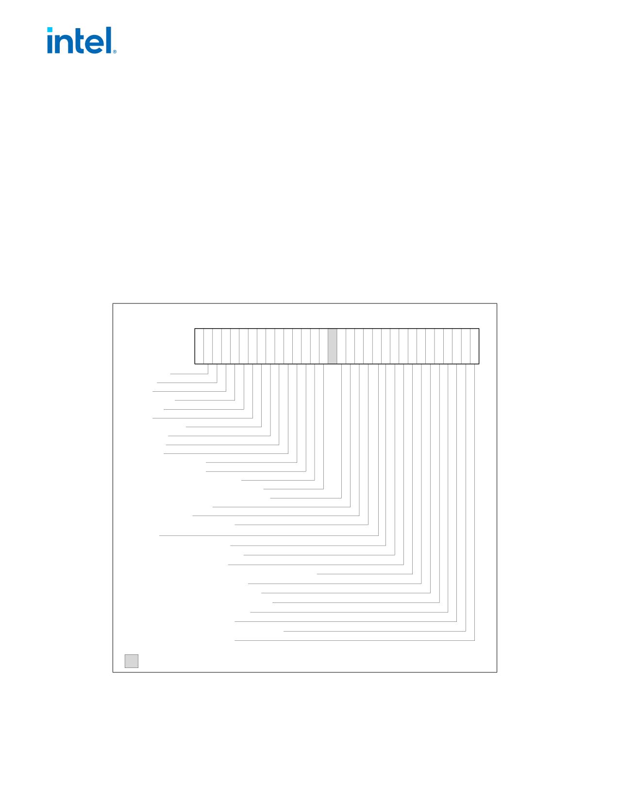
FUTURE INTEL® ARCHITECTURE INSTRUCTION EXTENSIONS AND FEATURES
• Brand index (low byte of EBX) - this number provides an entry into a brand string table that contains brand
strings for IA-32 processors. More information about this field is provided later in this section.
• CLFLUSH instruction cache line size (second byte of EBX) - this number indicates the size of the cache line
flushed with CLFLUSH instruction in 8-byte increments. This field was introduced in the Pentium 4 processor.
• Local APIC ID (high byte of EBX) - this number is the 8-bit ID that is assigned to the local APIC on the
processor during power up. This field was introduced in the Pentium 4 processor.
INPUT EAX = 01H: Returns Feature Information in ECX and EDX
When CPUID executes with EAX set to 01H, feature information is returned in ECX and EDX.
• Figure 1-2 and Table 1-5 show encodings for ECX.
• Figure 1-3 and Table 1-6 show encodings for EDX.
For all feature flags, a 1 indicates that the feature is supported. Use Intel to properly interpret feature flags.
NOTE
Software must confirm that a processor feature is present using feature flags returned by CPUID
prior to using the feature. Software should not depend on future offerings retaining all features.
31 30 29 28 27 26 25 24 23 22 21 20 19 18 17 16 15 14 13 12 11 10 9
8
7
6
5
4
3
2
1
0
ECX
0
RDRAND
F16C
AVX
OSXSAVE
XSAVE
AES
TSC-Deadline
POPCNT
MOVBE
x2APIC
SSE4_2 - SSE4.2
SSE4_1 - SSE4.1
DCA - Direct Cache Access
PCID - Process-context Identifiers
PDCM - Perf/Debug Capability MSR
xTPR Update Control
CMPXCHG16B
FMA - Fused Multiply Add
SDBG
CNXT-ID - L1 Context ID
SSSE3 - SSSE3 Extensions
TM2 - Thermal Monitor 2
EST - Enhanced Intel SpeedStep® Technology
SMX - Safer Mode Extensions
VMX - Virtual Machine Extensions
DS-CPL - CPL Qualified Debug Store
MONITOR - MONITOR/MWAIT
DTES64 - 64-bit DS Area
PCLMULQDQ - Carryless Multiplication
SSE3 - SSE3 Extensions
Reserved
Figure 1-2. Feature Information Returned in the ECX Register
1-32
Document Number: 319433-050

FUTURE INTEL® ARCHITECTURE INSTRUCTION EXTENSIONS AND FEATURES
Table 1-5. Feature Information Returned in the ECX Register
Bit #
Mnemonic
Description
0
SSE3
Intel® Streaming SIMD Extensions 3 (Intel® SSE3). A value of 1 indicates the processor supports this
technology.
1
PCLMULQDQ
A value of 1 indicates the processor supports the PCLMULQDQ instruction.
2
DTES64
64-bit DS Area. A value of 1 indicates the processor supports DS area using 64-bit layout.
3
MONITOR
MONITOR/MWAIT. A value of 1 indicates the processor supports this feature.
4
DS-CPL
CPL Qualified Debug Store. A value of 1 indicates the processor supports the extensions to the
Debug Store feature to allow for branch message storage qualified by CPL.
5
VMX
Virtual Machine Extensions. A value of 1 indicates that the processor supports this technology.
6
SMX
Safer Mode Extensions. A value of 1 indicates that the processor supports this technology. See
Chapter 7, “Safer Mode Extensions Reference.”
7
EST
Enhanced Intel SpeedStep® Technology. A value of 1 indicates that the processor supports this
technology.
8
TM2
Thermal Monitor 2. A value of 1 indicates whether the processor supports this technology.
9
SSSE3
A value of 1 indicates the presence of the Supplemental Streaming SIMD Extensions 3 (SSSE3). A
value of 0 indicates the instruction extensions are not present in the processor.
10
CNXT-ID
L1 Context ID. A value of 1 indicates the L1 data cache mode can be set to either adaptive mode or
shared mode. A value of 0 indicates this feature is not supported. See definition of the
IA32_MISC_ENABLE MSR Bit 24 (L1 Data Cache Context Mode) for details.
11
SDBG
A value of 1 indicates the processor supports IA32_DEBUG_INTERFACE MSR for silicon debug.
12
FMA
A value of 1 indicates the processor supports FMA extensions using YMM state.
13
CMPXCHG16B
CMPXCHG16B Available. A value of 1 indicates that the feature is available.
14
xTPR Update
xTPR Update Control. A value of 1 indicates that the processor supports changing
Control
IA32_MISC_ENABLES[bit 23].
15
PDCM
Perfmon and Debug Capability. A value of 1 indicates the processor supports the performance and
debug feature indication MSR IA32_PERF_CAPABILITIES.
16
Reserved
Reserved.
17
PCID
Process-context identifiers. A value of 1 indicates that the processor supports PCIDs and that
software may set CR4.PCIDE to 1.
18
DCA
A value of 1 indicates the processor supports the ability to prefetch data from a memory mapped
device.
19
SSE4.1
A value of 1 indicates that the processor supports SSE4.1.
20
SSE4.2
A value of 1 indicates that the processor supports SSE4.2.
21
x2APIC
A value of 1 indicates that the processor supports x2APIC feature.
22
MOVBE
A value of 1 indicates that the processor supports MOVBE instruction.
23
POPCNT
A value of 1 indicates that the processor supports the POPCNT instruction.
24
TSC-Deadline
A value of 1 indicates that the processor’s local APIC timer supports one-shot operation using a TSC
deadline value.
25
AES
A value of 1 indicates that the processor supports the AESNI instruction extensions.
26
XSAVE
A value of 1 indicates that the processor supports the XSAVE/XRSTOR processor extended states
feature, the XSETBV/XGETBV instructions, and XCR0.
27
OSXSAVE
A value of 1 indicates that the OS has set CR4.OSXSAVE[bit 18] to enable XSETBV/XGETBV
instructions to access XCR0 and to support processor extended state management using
XSAVE/XRSTOR.
28
AVX
A value of 1 indicates that processor supports AVX instructions operating on 256-bit YMM state, and
three-operand encoding of 256-bit and 128-bit SIMD instructions.
Document Number: 319433-050
1-33
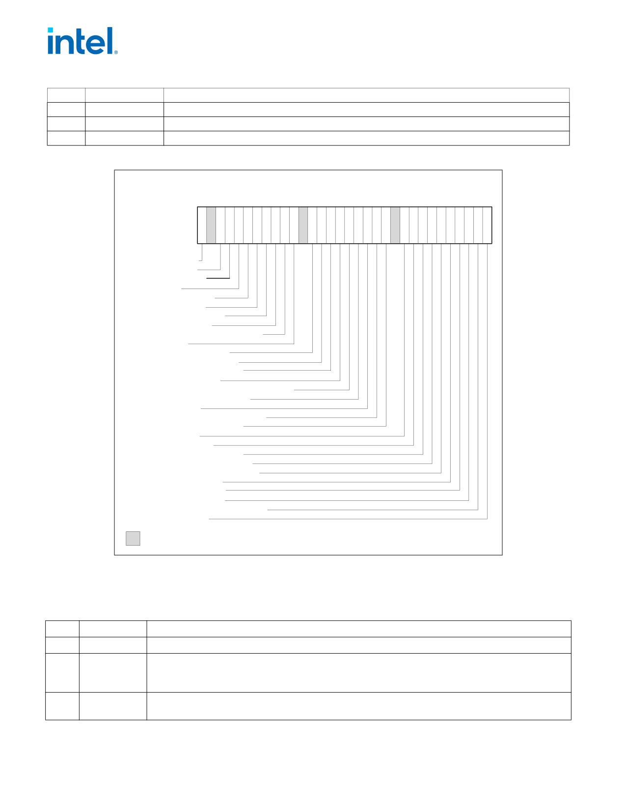
FUTURE INTEL® ARCHITECTURE INSTRUCTION EXTENSIONS AND FEATURES
Table 1-5. Feature Information Returned in the ECX Register (Continued)
Bit #
Mnemonic
Description
29
F16C
A value of 1 indicates that processor supports 16-bit floating-point conversion instructions.
30
RDRAND
A value of 1 indicates that processor supports RDRAND instruction.
31
Not Used
Always return 0.
3130292827262524 23 22 21 20 19 18 17 16 15 1413 12 11 10 9
8
7
6
5 4
3
2
1
0
EDX
PBE-Pend. Brk. EN.
TM-Therm. Monitor
HTT-Multi-threading
SS-Self Snoop
SSE2-SSE2 Extensions
SSE-SSE Extensions
FXSR-FXSAVE/FXRSTOR
MMX-MMX Technology
ACPI-Thermal Monitor and Clock Ctrl
DS-Debug Store
CLFSH-CFLUSH instruction
PSN-Processor Serial Number
PSE-36 - Page Size Extension
PAT-Page Attribute Table
CMOV-Conditional Move/Compare Instruction
MCA-Machine Check Architecture
PGE-PTE Global Bit
MTRR-Memory Type Range Registers
SEP-SYSENTER and SYSEXIT
APIC-APIC on Chip
CX8-CMPXCHG8B Inst.
MCE-Machine Check Exception
PAE-Physical Address Extensions
MSR-RDMSR and WRMSR Support
TSC-Time Stamp Counter
PSE-Page Size Extensions
DE-Debugging Extensions
VME-Virtual-8086 Mode Enhancement
FPU-x87 FPU on Chip
Reserved
Figure 1-3. Feature Information Returned in the EDX Register
Table 1-6. More on Feature Information Returned in the EDX Register
Bit #
Mnemonic
Description
0
FPU
Floating-point Unit On-Chip. The processor contains an x87 FPU.
1
VME
Virtual 8086 Mode Enhancements. Virtual 8086 mode enhancements, including CR4.VME for controlling
the feature, CR4.PVI for protected mode virtual interrupts, software interrupt indirection, expansion of the
TSS with the software indirection bitmap, and EFLAGS.VIF and EFLAGS.VIP flags.
2
DE
Debugging Extensions. Support for I/O breakpoints, including CR4.DE for controlling the feature, and
optional trapping of accesses to DR4 and DR5.
1-34
Document Number: 319433-050

FUTURE INTEL® ARCHITECTURE INSTRUCTION EXTENSIONS AND FEATURES
Table 1-6. More on Feature Information Returned in the EDX Register(Continued)
Bit #
Mnemonic
Description
3
PSE
Page Size Extension. Large pages of size 4 MByte are supported, including CR4.PSE for controlling the
feature, the defined dirty bit in PDE (Page Directory Entries), optional reserved bit trapping in CR3, PDEs,
and PTEs.
4
TSC
Time Stamp Counter. The RDTSC instruction is supported, including CR4.TSD for controlling privilege.
5
MSR
Model Specific Registers RDMSR and WRMSR Instructions. The RDMSR and WRMSR instructions are
supported. Some of the MSRs are implementation dependent.
6
PAE
Physical Address Extension. Physical addresses greater than 32 bits are supported: extended page table
entry formats, an extra level in the page translation tables is defined, 2-MByte pages are supported instead
of 4 Mbyte pages if PAE bit is 1. The actual number of address bits beyond 32 is not defined, and is
implementation specific.
7
MCE
Machine Check Exception. Exception 18 is defined for Machine Checks, including CR4.MCE for controlling
the feature. This feature does not define the model-specific implementations of machine-check error
logging, reporting, and processor shutdowns. Machine Check exception handlers may have to depend on
processor version to do model specific processing of the exception, or test for the presence of the Machine
Check feature.
8
CX8
CMPXCHG8B Instruction. The compare-and-exchange 8 bytes (64 bits) instruction is supported (implicitly
locked and atomic).
9
APIC
APIC On-Chip. The processor contains an Advanced Programmable Interrupt Controller (APIC), responding
to memory mapped commands in the physical address range FFFE0000H to FFFE0FFFH (by default - some
processors permit the APIC to be relocated).
10
Reserved
Reserved.
11
SEP
SYSENTER and SYSEXIT Instructions. The SYSENTER and SYSEXIT and associated MSRs are supported.
12
MTRR
Memory Type Range Registers. MTRRs are supported. The MTRRcap MSR contains feature bits that
describe what memory types are supported, how many variable MTRRs are supported, and whether fixed
MTRRs are supported.
13
PGE
Page Global Bit. The global bit is supported in paging-structure entries that map a page, indicating TLB
entries that are common to different processes and need not be flushed. The CR4.PGE bit controls this
feature.
14
MCA
Machine Check Architecture. The Machine Check Architecture, which provides a compatible mechanism for
error reporting in P6 family, Pentium 4, Intel Xeon processors, and future processors, is supported. The
MCG_CAP MSR contains feature bits describing how many banks of error reporting MSRs are supported.
15
CMOV
Conditional Move Instructions. The conditional move instruction CMOV is supported. In addition, if x87
FPU is present as indicated by the CPUID.FPU feature bit, then the FCOMI and FCMOV instructions are
supported
16
PAT
Page Attribute Table. Page Attribute Table is supported. This feature augments the Memory Type Range
Registers (MTRRs), allowing an operating system to specify attributes of memory accessed through a linear
address on a 4KB granularity.
17
PSE-36
36-Bit Page Size Extension. 4-MByte pages addressing physical memory beyond 4 GBytes are supported
with 32-bit paging. This feature indicates that upper bits of the physical address of a 4-MByte page are
encoded in bits 20:13 of the page-directory entry. Such physical addresses are limited by MAXPHYADDR
and may be up to 40 bits in size.
18
PSN
Processor Serial Number. The processor supports the 96-bit processor identification number feature and
the feature is enabled.
19
CLFSH
CLFLUSH Instruction. CLFLUSH Instruction is supported.
20
Reserved
Reserved.
Document Number: 319433-050
1-35

FUTURE INTEL® ARCHITECTURE INSTRUCTION EXTENSIONS AND FEATURES
Table 1-6. More on Feature Information Returned in the EDX Register(Continued)
Bit #
Mnemonic
Description
21
DS
Debug Store. The processor supports the ability to write debug information into a memory resident buffer.
This feature is used by the branch trace store (BTS) and precise event-based sampling (PEBS) facilities (see
Chapter 24, “Introduction to Virtual-Machine Extensions,” in the Intel® 64 and IA-32 Architectures
Software Developer’s Manual, Volume 3C).
22
ACPI
Thermal Monitor and Software Controlled Clock Facilities. The processor implements internal MSRs that
allow processor temperature to be monitored and processor performance to be modulated in predefined
duty cycles under software control.
23
MMX
Intel MMX Technology. The processor supports the Intel MMX technology.
24
FXSR
FXSAVE and FXRSTOR Instructions. The FXSAVE and FXRSTOR instructions are supported for fast save
and restore of the floating-point context. Presence of this bit also indicates that CR4.OSFXSR is available
for an operating system to indicate that it supports the FXSAVE and FXRSTOR instructions.
25
SSE
SSE. The processor supports the SSE extensions.
26
SSE2
SSE2. The processor supports the SSE2 extensions.
27
SS
Self Snoop. The processor supports the management of conflicting memory types by performing a snoop
of its own cache structure for transactions issued to the bus.
28
HTT
Max APIC IDs reserved field is Valid. A value of 0 for HTT indicates there is only a single logical processor
in the package and software should assume only a single APIC ID is reserved. A value of 1 for HTT indicates
the value in CPUID.1.EBX[23:16] (the Maximum number of addressable IDs for logical processors in this
package) is valid for the package.
29
TM
Thermal Monitor. The processor implements the thermal monitor automatic thermal control circuitry (TCC).
30
Reserved
Reserved.
31
PBE
Pending Break Enable. The processor supports the use of the FERR#/PBE# pin when the processor is in
the stop-clock state (STPCLK# is asserted) to signal the processor that an interrupt is pending and that the
processor should return to normal operation to handle the interrupt. Bit 10 (PBE enable) in the
IA32_MISC_ENABLE MSR enables this capability.
INPUT EAX = 02H: Cache and TLB Information Returned in EAX, EBX, ECX, EDX
When CPUID executes with EAX set to 02H, the processor returns information about the processor’s internal caches
and TLBs in the EAX, EBX, ECX, and EDX registers.
The encoding is as follows:
• The least-significant byte in register EAX (register AL) indicates the number of times the CPUID instruction
must be executed with an input value of 02H to get a complete description of the processor’s caches and TLBs.
The first member of the family of Pentium 4 processors will return a 01H.
• The most significant bit (bit 31) of each register indicates whether the register contains valid information (set
to 0) or is reserved (set to 1).
• If a register contains valid information, the information is contained in 1 byte descriptors. Table 1-7 shows the
encoding of these descriptors. Note that the order of descriptors in the EAX, EBX, ECX, and EDX registers is not
defined; that is, specific bytes are not designated to contain descriptors for specific cache or TLB types. The
descriptors may appear in any order.
Table 1-7. Encoding of Cache and TLB Descriptors
Descriptor
Type
Cache or TLB Description
Value
00H
General
Null descriptor, this byte contains no information.
01H
TLB
Instruction TLB: 4 KByte pages, 4-way set associative, 32 entries.
02H
TLB
Instruction TLB: 4 MByte pages, 4-way set associative, 2 entries.
03H
TLB
Data TLB: 4 KByte pages, 4-way set associative, 64 entries.
1-36
Document Number: 319433-050

FUTURE INTEL® ARCHITECTURE INSTRUCTION EXTENSIONS AND FEATURES
Table 1-7. Encoding of Cache and TLB Descriptors (Continued)
Descriptor
Type
Cache or TLB Description
Value
04H
TLB
Data TLB: 4 MByte pages, 4-way set associative, 8 entries.
05H
TLB
Data TLB1: 4 MByte pages, 4-way set associative, 32 entries.
06H
Cache
1st-level instruction cache: 8 KBytes, 4-way set associative, 32 byte line size.
08H
Cache
1st-level instruction cache: 16 KBytes, 4-way set associative, 32 byte line size.
09H
Cache
1st-level instruction cache: 32KBytes, 4-way set associative, 64 byte line size.
0AH
Cache
1st-level data cache: 8 KBytes, 2-way set associative, 32 byte line size.
0BH
TLB
Instruction TLB: 4 MByte pages, 4-way set associative, 4 entries.
0CH
Cache
1st-level data cache: 16 KBytes, 4-way set associative, 32 byte line size.
0DH
Cache
1st-level data cache: 16 KBytes, 4-way set associative, 64 byte line size.
0EH
Cache
1st-level data cache: 24 KBytes, 6-way set associative, 64 byte line size.
1DH
Cache
2nd-level cache: 128 KBytes, 2-way set associative, 64 byte line size.
21H
Cache
2nd-level cache: 256 KBytes, 8-way set associative, 64 byte line size.
22H
Cache
3rd-level cache: 512 KBytes, 4-way set associative, 64 byte line size, 2 lines per sector.
23H
Cache
3rd-level cache: 1 MBytes, 8-way set associative, 64 byte line size, 2 lines per sector.
24H
Cache
2nd-level cache: 1 MBytes, 16-way set associative, 64 byte line size.
25H
Cache
3rd-level cache: 2 MBytes, 8-way set associative, 64 byte line size, 2 lines per sector.
29H
Cache
3rd-level cache: 4 MBytes, 8-way set associative, 64 byte line size, 2 lines per sector.
2CH
Cache
1st-level data cache: 32 KBytes, 8-way set associative, 64 byte line size.
30H
Cache
1st-level instruction cache: 32 KBytes, 8-way set associative, 64 byte line size.
40H
Cache
No 2nd-level cache or, if processor contains a valid 2nd-level cache, no 3rd-level cache.
41H
Cache
2nd-level cache: 128 KBytes, 4-way set associative, 32 byte line size.
42H
Cache
2nd-level cache: 256 KBytes, 4-way set associative, 32 byte line size.
43H
Cache
2nd-level cache: 512 KBytes, 4-way set associative, 32 byte line size.
44H
Cache
2nd-level cache: 1 MByte, 4-way set associative, 32 byte line size.
45H
Cache
2nd-level cache: 2 MByte, 4-way set associative, 32 byte line size.
46H
Cache
3rd-level cache: 4 MByte, 4-way set associative, 64 byte line size.
47H
Cache
3rd-level cache: 8 MByte, 8-way set associative, 64 byte line size.
48H
Cache
2nd-level cache: 3MByte, 12-way set associative, 64 byte line size.
49H
Cache
3rd-level cache: 4MB, 16-way set associative, 64-byte line size (Intel Xeon processor MP, Family 0FH,
Model 06H);
2nd-level cache: 4 MByte, 16-way set associative, 64 byte line size.
4AH
Cache
3rd-level cache: 6MByte, 12-way set associative, 64 byte line size.
4BH
Cache
3rd-level cache: 8MByte, 16-way set associative, 64 byte line size.
4CH
Cache
3rd-level cache: 12MByte, 12-way set associative, 64 byte line size.
4DH
Cache
3rd-level cache: 16MByte, 16-way set associative, 64 byte line size.
4EH
Cache
2nd-level cache: 6MByte, 24-way set associative, 64 byte line size.
4FH
TLB
Instruction TLB: 4 KByte pages, 32 entries.
50H
TLB
Instruction TLB: 4 KByte and 2-MByte or 4-MByte pages, 64 entries.
51H
TLB
Instruction TLB: 4 KByte and 2-MByte or 4-MByte pages, 128 entries.
52H
TLB
Instruction TLB: 4 KByte and 2-MByte or 4-MByte pages, 256 entries.
55H
TLB
Instruction TLB: 2-MByte or 4-MByte pages, fully associative, 7 entries.
Document Number: 319433-050
1-37

FUTURE INTEL® ARCHITECTURE INSTRUCTION EXTENSIONS AND FEATURES
Table 1-7. Encoding of Cache and TLB Descriptors (Continued)
Descriptor
Type
Cache or TLB Description
Value
56H
TLB
Data TLB0: 4 MByte pages, 4-way set associative, 16 entries.
57H
TLB
Data TLB0: 4 KByte pages, 4-way associative, 16 entries.
59H
TLB
Data TLB0: 4 KByte pages, fully associative, 16 entries.
5AH
TLB
Data TLB0: 2 MByte or 4 MByte pages, 4-way set associative, 32 entries.
5BH
TLB
Data TLB: 4 KByte and 4 MByte pages, 64 entries.
5CH
TLB
Data TLB: 4 KByte and 4 MByte pages,128 entries.
5DH
TLB
Data TLB: 4 KByte and 4 MByte pages,256 entries.
60H
Cache
1st-level data cache: 16 KByte, 8-way set associative, 64 byte line size.
61H
TLB
Instruction TLB: 4 KByte pages, fully associative, 48 entries.
63H
TLB
Data TLB: 2 MByte or 4 MByte pages, 4-way set associative, 32 entries and a separate array with 1
GByte pages, 4-way set associative, 4 entries.
64H
TLB
Data TLB: 4 KByte pages, 4-way set associative, 512 entries.
66H
Cache
1st-level data cache: 8 KByte, 4-way set associative, 64 byte line size.
67H
Cache
1st-level data cache: 16 KByte, 4-way set associative, 64 byte line size.
68H
Cache
1st-level data cache: 32 KByte, 4-way set associative, 64 byte line size.
6AH
Cache
uTLB: 4 KByte pages, 8-way set associative, 64 entries.
6BH
Cache
DTLB: 4 KByte pages, 8-way set associative, 256 entries.
6CH
Cache
DTLB: 2M/4M pages, 8-way set associative, 128 entries.
6DH
Cache
DTLB: 1 GByte pages, fully associative, 16 entries.
70H
Cache
Trace cache: 12 K-μop, 8-way set associative.
71H
Cache
Trace cache: 16 K-μop, 8-way set associative.
72H
Cache
Trace cache: 32 K-μop, 8-way set associative.
76H
TLB
Instruction TLB: 2M/4M pages, fully associative, 8 entries.
78H
Cache
2nd-level cache: 1 MByte, 4-way set associative, 64byte line size.
79H
Cache
2nd-level cache: 128 KByte, 8-way set associative, 64 byte line size, 2 lines per sector.
7AH
Cache
2nd-level cache: 256 KByte, 8-way set associative, 64 byte line size, 2 lines per sector.
7BH
Cache
2nd-level cache: 512 KByte, 8-way set associative, 64 byte line size, 2 lines per sector.
7CH
Cache
2nd-level cache: 1 MByte, 8-way set associative, 64 byte line size, 2 lines per sector.
7DH
Cache
2nd-level cache: 2 MByte, 8-way set associative, 64byte line size.
7FH
Cache
2nd-level cache: 512 KByte, 2-way set associative, 64-byte line size.
80H
Cache
2nd-level cache: 512 KByte, 8-way set associative, 64-byte line size.
82H
Cache
2nd-level cache: 256 KByte, 8-way set associative, 32 byte line size.
83H
Cache
2nd-level cache: 512 KByte, 8-way set associative, 32 byte line size.
84H
Cache
2nd-level cache: 1 MByte, 8-way set associative, 32 byte line size.
85H
Cache
2nd-level cache: 2 MByte, 8-way set associative, 32 byte line size.
86H
Cache
2nd-level cache: 512 KByte, 4-way set associative, 64 byte line size.
87H
Cache
2nd-level cache: 1 MByte, 8-way set associative, 64 byte line size.
A0H
DTLB
DTLB: 4k pages, fully associative, 32 entries.
B0H
TLB
Instruction TLB: 4 KByte pages, 4-way set associative, 128 entries.
B1H
TLB
Instruction TLB: 2M pages, 4-way, 8 entries or 4M pages, 4-way, 4 entries.
B2H
TLB
Instruction TLB: 4KByte pages, 4-way set associative, 64 entries.
1-38
Document Number: 319433-050

FUTURE INTEL® ARCHITECTURE INSTRUCTION EXTENSIONS AND FEATURES
Table 1-7. Encoding of Cache and TLB Descriptors (Continued)
Descriptor
Type
Cache or TLB Description
Value
B3H
TLB
Data TLB: 4 KByte pages, 4-way set associative, 128 entries.
B4H
TLB
Data TLB1: 4 KByte pages, 4-way associative, 256 entries.
B5H
TLB
Instruction TLB: 4KByte pages, 8-way set associative, 64 entries.
B6H
TLB
Instruction TLB: 4KByte pages, 8-way set associative, 128 entries.
BAH
TLB
Data TLB1: 4 KByte pages, 4-way associative, 64 entries.
C0H
TLB
Data TLB: 4 KByte and 4 MByte pages, 4-way associative, 8 entries.
C1H
STLB
Shared 2nd-Level TLB: 4 KByte/2MByte pages, 8-way associative, 1024 entries.
C2H
DTLB
DTLB: 4 KByte/2 MByte pages, 4-way associative, 16 entries.
C3H
STLB
Shared 2nd-Level TLB: 4 KByte /2 MByte pages, 6-way associative, 1536 entries. Also 1GBbyte pages,
4-way, 16 entries.
C4H
DTLB
DTLB: 2M/4M Byte pages, 4-way associative, 32 entries.
CAH
STLB
Shared 2nd-Level TLB: 4 KByte pages, 4-way associative, 512 entries.
D0H
Cache
3rd-level cache: 512 KByte, 4-way set associative, 64 byte line size.
D1H
Cache
3rd-level cache: 1 MByte, 4-way set associative, 64 byte line size.
D2H
Cache
3rd-level cache: 2 MByte, 4-way set associative, 64 byte line size.
D6H
Cache
3rd-level cache: 1 MByte, 8-way set associative, 64 byte line size.
D7H
Cache
3rd-level cache: 2 MByte, 8-way set associative, 64 byte line size.
D8H
Cache
3rd-level cache: 4 MByte, 8-way set associative, 64 byte line size.
DCH
Cache
3rd-level cache: 1.5 MByte, 12-way set associative, 64 byte line size.
DDH
Cache
3rd-level cache: 3 MByte, 12-way set associative, 64 byte line size.
DEH
Cache
3rd-level cache: 6 MByte, 12-way set associative, 64 byte line size.
E2H
Cache
3rd-level cache: 2 MByte, 16-way set associative, 64 byte line size.
E3H
Cache
3rd-level cache: 4 MByte, 16-way set associative, 64 byte line size.
E4H
Cache
3rd-level cache: 8 MByte, 16-way set associative, 64 byte line size.
EAH
Cache
3rd-level cache: 12MByte, 24-way set associative, 64 byte line size.
EBH
Cache
3rd-level cache: 18MByte, 24-way set associative, 64 byte line size.
ECH
Cache
3rd-level cache: 24MByte, 24-way set associative, 64 byte line size.
F0H
Prefetch
64-Byte prefetching.
F1H
Prefetch
128-Byte prefetching.
FEH
General
CPUID leaf 2 does not report TLB descriptor information; use CPUID leaf 18H to query TLB and other
address translation parameters.
FFH
General
CPUID leaf 2 does not report cache descriptor information, use CPUID leaf 4 to query cache parameters.
Example 1-1. Example of Cache and TLB Interpretation
The first member of the family of Pentium 4 processors returns the following information about caches and TLBs
when the CPUID executes with an input value of 2:
EAX
66 5B 50 01H
EBX
0H
ECX
0H
EDX
00 7A 70 00H
Which means:
Document Number: 319433-050
1-39
FUTURE INTEL® ARCHITECTURE INSTRUCTION EXTENSIONS AND FEATURES
• The least-significant byte (byte 0) of register EAX is set to 01H. This indicates that CPUID needs to be executed
once with an input value of 2 to retrieve complete information about caches and TLBs.
• The most-significant bit of all four registers (EAX, EBX, ECX, and EDX) is set to 0, indicating that each register
contains valid 1-byte descriptors.
• Bytes 1, 2, and 3 of register EAX indicate that the processor has:
- 50H - a 64-entry instruction TLB, for mapping 4-KByte and 2-MByte or 4-MByte pages.
- 5BH - a 64-entry data TLB, for mapping 4-KByte and 4-MByte pages.
- 66H - an 8-KByte 1st level data cache, 4-way set associative, with a 64-Byte cache line size.
• The descriptors in registers EBX and ECX are valid, but contain NULL descriptors.
• Bytes 0, 1, 2, and 3 of register EDX indicate that the processor has:
- 00H - NULL descriptor.
- 70H - Trace cache: 12 K-μop, 8-way set associative.
- 7AH - a 256-KByte 2nd level cache, 8-way set associative, with a sectored, 64-byte cache line size.
- 00H - NULL descriptor.
INPUT EAX = 04H: Returns Deterministic Cache Parameters for Each Level
When CPUID executes with EAX set to 04H and ECX contains an index value, the processor returns encoded data
that describe a set of deterministic cache parameters (for the cache level associated with the input in ECX). Valid
index values start from 0.
Software can enumerate the deterministic cache parameters for each level of the cache hierarchy starting with an
index value of 0, until the parameters report the value associated with the cache type field is 0. The architecturally
defined fields reported by deterministic cache parameters are documented in Table 1-3.
The CPUID leaf 4 also reports data that can be used to derive the topology of processor cores in a physical package.
This information is constant for all valid index values. Software can query the raw data reported by executing
CPUID with EAX=04H and ECX=0H and use it as part of the topology enumeration algorithm described in Chapter
9, “Multiple-Processor Management,” in the Intel® 64 and IA-32 Architectures Software Developer’s Manual,
Volume 3A.
INPUT EAX = 05H: Returns MONITOR and MWAIT Features
When CPUID executes with EAX set to 05H, the processor returns information about features available to
MONITOR/MWAIT instructions. The MONITOR instruction is used for address-range monitoring in conjunction with
MWAIT instruction. The MWAIT instruction optionally provides additional extensions for advanced power manage-
ment. See Table 1-3.
INPUT EAX = 06H: Returns Thermal and Power Management Features
When CPUID executes with EAX set to 06H, the processor returns information about thermal and power manage-
ment features. See Table 1-3.
INPUT EAX = 07H: Returns Structured Extended Feature Enumeration Information
When CPUID executes with EAX set to 07H and ECX = 0H, the processor returns information about the maximum
number of sub-leaves that contain extended feature flags. See Table 1-3.
When CPUID executes with EAX set to 07H and ECX = n (n ≥ 1 and less than the number of non-zero bits in
CPUID.(EAX=07H, ECX= 0H).EAX), the processor returns information about extended feature flags. See Table 1-3.
In sub-leaf 0, only EAX has the number of sub-leaves. In sub-leaf 0, EBX, ECX & EDX all contain extended feature
flags.
INPUT EAX = 09H: Returns Direct Cache Access Information
When CPUID executes with EAX set to 09H, the processor returns information about Direct Cache Access capabili-
ties. See Table 1-3.
1-40
Document Number: 319433-050
FUTURE INTEL® ARCHITECTURE INSTRUCTION EXTENSIONS AND FEATURES
INPUT EAX = 0AH: Returns Architectural Performance Monitoring Features
When CPUID executes with EAX set to 0AH, the processor returns information about support for architectural
performance monitoring capabilities. Architectural performance monitoring is supported if the version ID (see
Table 1-3) is greater than Pn 0. See Table 1-3.
For each version of architectural performance monitoring capability, software must enumerate this leaf to discover
the programming facilities and the architectural performance events available in the processor. The details are
described in Chapter 18, “Debug, Branch Profile, TSC, and Intel® Resource Director Technology (Intel® RDT)
Features,” in the Intel® 64 and IA-32 Architectures Software Developer’s Manual, Volume 3A.
INPUT EAX = 0BH: Returns Extended Topology Information
CPUID leaf 1FH is a preferred superset to leaf 0BH. Intel recommends first checking for the existence of Leaf 1FH
before using leaf 0BH.
When CPUID executes with EAX set to 0BH, the processor returns information about extended topology enumera-
tion data. Software must detect the presence of CPUID leaf 0BH by verifying (a) the highest leaf index supported
by CPUID is >= 0BH, and (b) CPUID.0BH:EBX[15:0] reports a non-zero value. See Table 1-3.
INPUT EAX = 0DH: Returns Processor Extended States Enumeration Information
When CPUID executes with EAX set to 0DH and ECX = 0H, the processor returns information about the bit-vector
representation of all processor state extensions that are supported in the processor and storage size requirements
of the XSAVE/XRSTOR area. See Table 1-3.
When CPUID executes with EAX set to 0DH and ECX = n (n > 1, and is a valid sub-leaf index), the processor returns
information about the size and offset of each processor extended state save area within the XSAVE/XRSTOR area.
See Table 1-3. Software can use the forward-extendable technique depicted below to query the valid sub-leaves
and obtain size and offset information for each processor extended state save area:
For i = 2 to 62 // sub-leaf 1 is reserved
IF (CPUID.(EAX=0DH, ECX=0):VECTOR[i] = 1 ) // VECTOR is the 64-bit value of EDX:EAX
Execute CPUID.(EAX=0DH, ECX = i) to examine size and offset for sub-leaf i;
FI;
INPUT EAX = 0FH: Returns Intel Resource Director Technology (Intel RDT) Monitoring Enumeration Information
When CPUID executes with EAX set to 0FH and ECX = 0, the processor returns information about the bit-vector
representation of QoS monitoring resource types that are supported in the processor and maximum range of RMID
values the processor can use to monitor of any supported resource types. Each bit, starting from bit 1, corresponds
to a specific resource type if the bit is set. The bit position corresponds to the sub-leaf index (or ResID) that soft-
ware must use to query QoS monitoring capability available for that type. See Table 1-3.
When CPUID executes with EAX set to 0FH and ECX = n (n >= 1, and is a valid ResID), the processor returns infor-
mation software can use to program IA32_PQR_ASSOC, IA32_QM_EVTSEL MSRs before reading QoS data from the
IA32_QM_CTR MSR.
INPUT EAX = 10H: Returns Intel Resource Director Technology (Intel RDT) Allocation Enumeration Information
When CPUID executes with EAX set to 10H and ECX = 0, the processor returns information about the bit-vector
representation of QoS Enforcement resource types that are supported in the processor. Each bit, starting from bit
1, corresponds to a specific resource type if the bit is set. The bit position corresponds to the sub-leaf index (or
ResID) that software must use to query QoS enforcement capability available for that type. See Table 1-3.
When CPUID executes with EAX set to 10H and ECX = n (n >= 1, and is a valid ResID), the processor returns infor-
mation about available classes of service and range of QoS mask MSRs that software can use to configure each
class of services using capability bit masks in the QoS Mask registers, IA32_resourceType_Mask_n.
INPUT EAX = 12H: Returns Intel SGX Enumeration Information
When CPUID executes with EAX set to 12H and ECX = 0H, the processor returns information about Intel SGX capa-
bilities. See Table 1-3.
Document Number: 319433-050
1-41
FUTURE INTEL® ARCHITECTURE INSTRUCTION EXTENSIONS AND FEATURES
When CPUID executes with EAX set to 12H and ECX = 1H, the processor returns information about Intel SGX attri-
butes. See Table 1-3.
When CPUID executes with EAX set to 12H and ECX = n (n > 1), the processor returns information about Intel SGX
Enclave Page Cache. See Table 1-3.
INPUT EAX = 14H: Returns Intel Processor Trace Enumeration Information
When CPUID executes with EAX set to 14H and ECX = 0H, the processor returns information about Intel Processor
Trace extensions. See Table 1-3.
When CPUID executes with EAX set to 14H and ECX = n (n > 0 and less than the number of non-zero bits in
CPUID.(EAX=14H, ECX= 0H).EAX), the processor returns information about packet generation in Intel Processor
Trace. See Table 1-3.
INPUT EAX = 15H: Returns Time Stamp Counter and Nominal Core Crystal Clock Information
When CPUID executes with EAX set to 15H and ECX = 0H, the processor returns information about Time Stamp
Counter and Core Crystal Clock. See Table 1-3.
INPUT EAX = 16H: Returns Processor Frequency Information
When CPUID executes with EAX set to 16H, the processor returns information about Processor Frequency Informa-
tion. See Table 1-3.
INPUT EAX = 17H: Returns System-On-Chip Information
When CPUID executes with EAX set to 17H, the processor returns information about the System-On-Chip Vendor
Attribute Enumeration. See Table 1-3.
INPUT EAX = 18H: Returns Deterministic Address Translation Parameters Information
When CPUID executes with EAX set to 18H, the processor returns information about the Deterministic Address
Translation Parameters. See Table 1-3.
INPUT EAX = 19H: Returns Key Locker Information
When CPUID executes with EAX set to 19H, the processor returns information about Key Locker. See Table 1-3.
INPUT EAX = 1AH: Returns Hybrid Information
When CPUID executes with EAX set to 1AH, the processor returns information about hybrid capabilities. See Table
1-3.
INPUT EAX = 1BH: Returns PCONFIG Information
When CPUID executes with EAX set to 1BH, the processor returns information about PCONFIG capabilities. This
information is enumerated in sub-leaves selected by the value of ECX (starting with 0).
Each sub-leaf of CPUID function 1BH enumerates its sub-leaf type in EAX. If a sub-leaf type is 0, the sub-leaf is
invalid and zero is returned in EBX, ECX, and EDX. In this case, all subsequent sub-leaves (selected by larger input
values of ECX) are also invalid.
The only valid sub-leaf type currently defined is 1, indicating that the sub-leaf enumerates target identifiers for the
PCONFIG instruction. Any non-zero value returned in EBX, ECX, or EDX indicates a valid target identifier of the
PCONFIG instruction (any value of zero should be ignored). Currently, TME-MK and TSE are the only defined
targets. TME-MK is indicated by identifier 1, and TSE is indicated by identifier 2. An identifier of 0 indicates an
invalid target. If TME-MK is a supported target, the MKTME_KEY_PROGRAM leaf of PCONFIG is available. If TSE is
a supported target, the TSE_KEY_PROGRAM and the TSE_KEY_PROGRAM_WRAPPED leaves of PCONFIG are avail-
able. See the “PCONFIG-Platform Configuration” instruction in Chapter 4 of the Intel® 64 and IA 32 Architectures
Software Developer's Manual, Volume 2B, for more information.
1-42
Document Number: 319433-050
FUTURE INTEL® ARCHITECTURE INSTRUCTION EXTENSIONS AND FEATURES
INPUT EAX = 1CH: Returns Last Branch Record Information
When CPUID executes with EAX set to 1CH, the processor returns information about LBRs (the architectural
feature). See Table 1-3.
INPUT EAX = 1DH: Returns Tile Information
When CPUID executes with EAX set to 1DH and ECX = 0H, the processor returns information about tile
architecture. See Table 1-3.
When CPUID executes with EAX set to 1DH and ECX = 1H, the processor returns information about tile palette 1.
See Table 1-3.
INPUT EAX = 1EH: Returns TMUL Information
When CPUID executes with EAX set to 1EH and ECX = 0H, the processor returns information about TMUL
capabilities. See Table 1-3.
INPUT EAX = 1FH: Returns V2 Extended Topology Information
When CPUID executes with EAX set to 1FH, the processor returns information about extended topology enumera-
tion data. Software must detect the presence of CPUID leaf 1FH by verifying (a) the highest leaf index supported
by CPUID is >= 1FH, and (b) CPUID.1FH:EBX[15:0] reports a non-zero value. See Table 1-3.
INPUT EAX = 20H: Returns Processor History Reset Information
When CPUID executes with EAX set to 20H, the processor returns information about processor history reset. See
Table 1-3.
INPUT EAX = 23H: Returns Architectural Performance Monitoring Extended Information
When CPUID executes with EAX set to 23H, the processor returns architectural performance monitoring extended
information. See Table 1-3.
METHODS FOR RETURNING BRANDING INFORMATION
Use the following techniques to access branding information:
1. Processor brand string method; this method also returns the processor’s maximum operating frequency
2. Processor brand index; this method uses a software supplied brand string table.
These two methods are discussed in the following sections. For methods that are available in early processors, see
Section: “Identification of Earlier IA-32 Processors” in Chapter 20 of the Intel® 64 and IA-32 Architectures Soft-
ware Developer’s Manual, Volume 1.
The Processor Brand String Method
Figure 1-4 describes the algorithm used for detection of the brand string. Processor brand identification software
should execute this algorithm on all Intel 64 and IA-32 processors.
This method (introduced with Pentium 4 processors) returns an ASCII brand identification string and the maximum
operating frequency of the processor to the EAX, EBX, ECX, and EDX registers.
Document Number: 319433-050
1-43
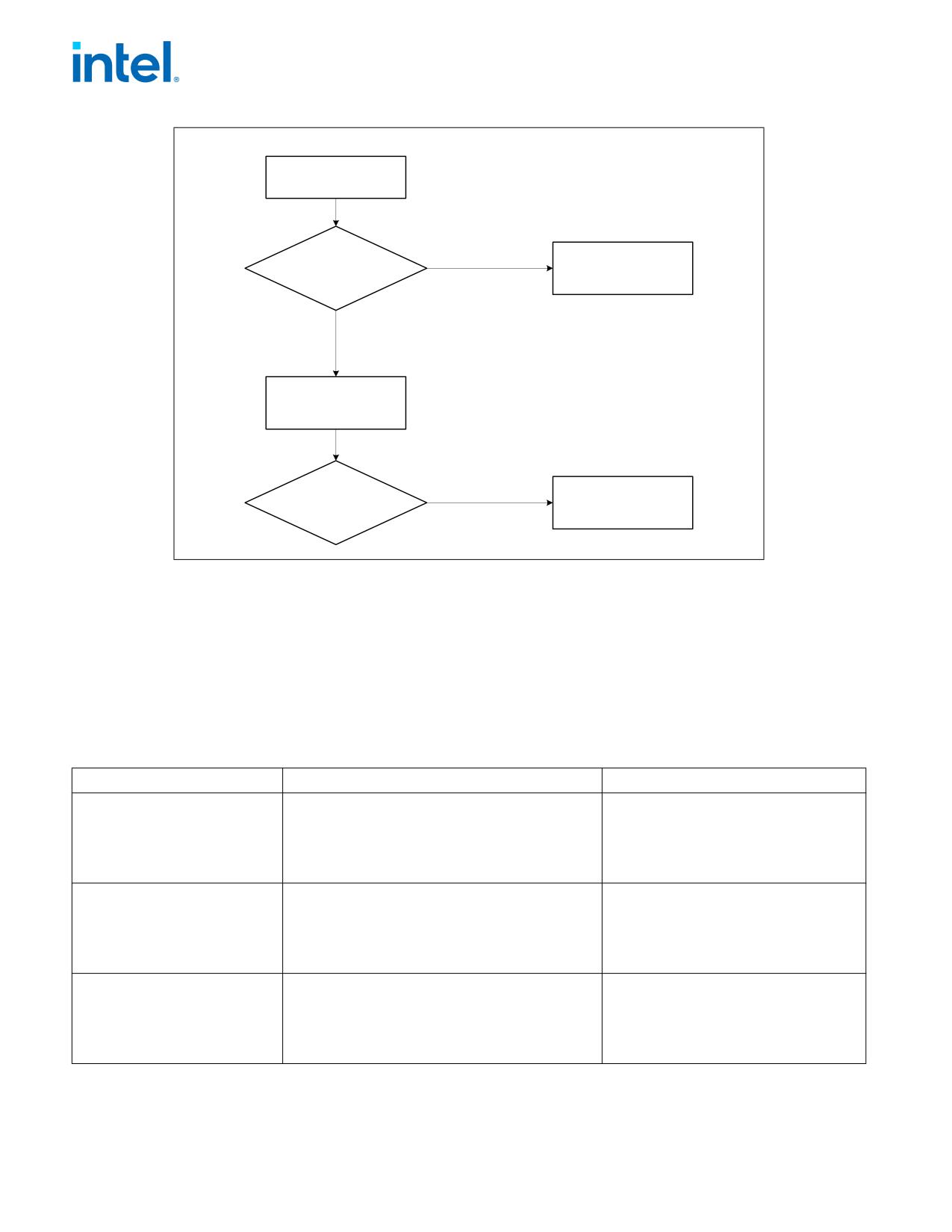
FUTURE INTEL® ARCHITECTURE INSTRUCTION EXTENSIONS AND FEATURES
Input: EAX=
0x80000000
CPUID
False
Processor Brand
IF (EAX & 0x80000000)
String Not
Supported
CPUID
True =
Function
Extended
Supported
EAX Return Value =
Max. Extended CPUID
Function Index
True
IF (EAX Return Value
Processor Brand
= 0x80000004)
String Supported
Figure 1-4. Determination of Support for the Processor Brand String
How Brand Strings Work
To use the brand string method, execute CPUID with EAX input of 8000002H through 80000004H. For each input
value, CPUID returns 16 ASCII characters using EAX, EBX, ECX, and EDX. The returned string will be NULL-termi-
nated.
Table 1-8 shows the brand string that is returned by the first processor in the Pentium 4 processor family.
Table 1-8. Processor Brand String Returned with Pentium 4 Processor
EAX Input Value
Return Values
ASCII Equivalent
80000002H
EAX = 20202020H
“
”
EBX = 20202020H
“
”
ECX = 20202020H
“
”
EDX = 6E492020H
“nI ”
80000003H
EAX = 286C6574H
“(let”
EBX = 50202952H
“P )R”
ECX = 69746E65H
“itne”
EDX = 52286D75H
“R(mu”
80000004H
EAX = 20342029H
“ 4 )”
EBX = 20555043H
“ UPC”
ECX = 30303531H
“0051”
EDX = 007A484DH
“\0zHM”
1-44
Document Number: 319433-050