Intel 64 and IA-32 Architectures. Software Developer’s Manual (Collection, 2023) - page 137
FUTURE INTEL® ARCHITECTURE INSTRUCTION EXTENSIONS AND FEATURES
Extracting the Maximum Processor Frequency from Brand Strings
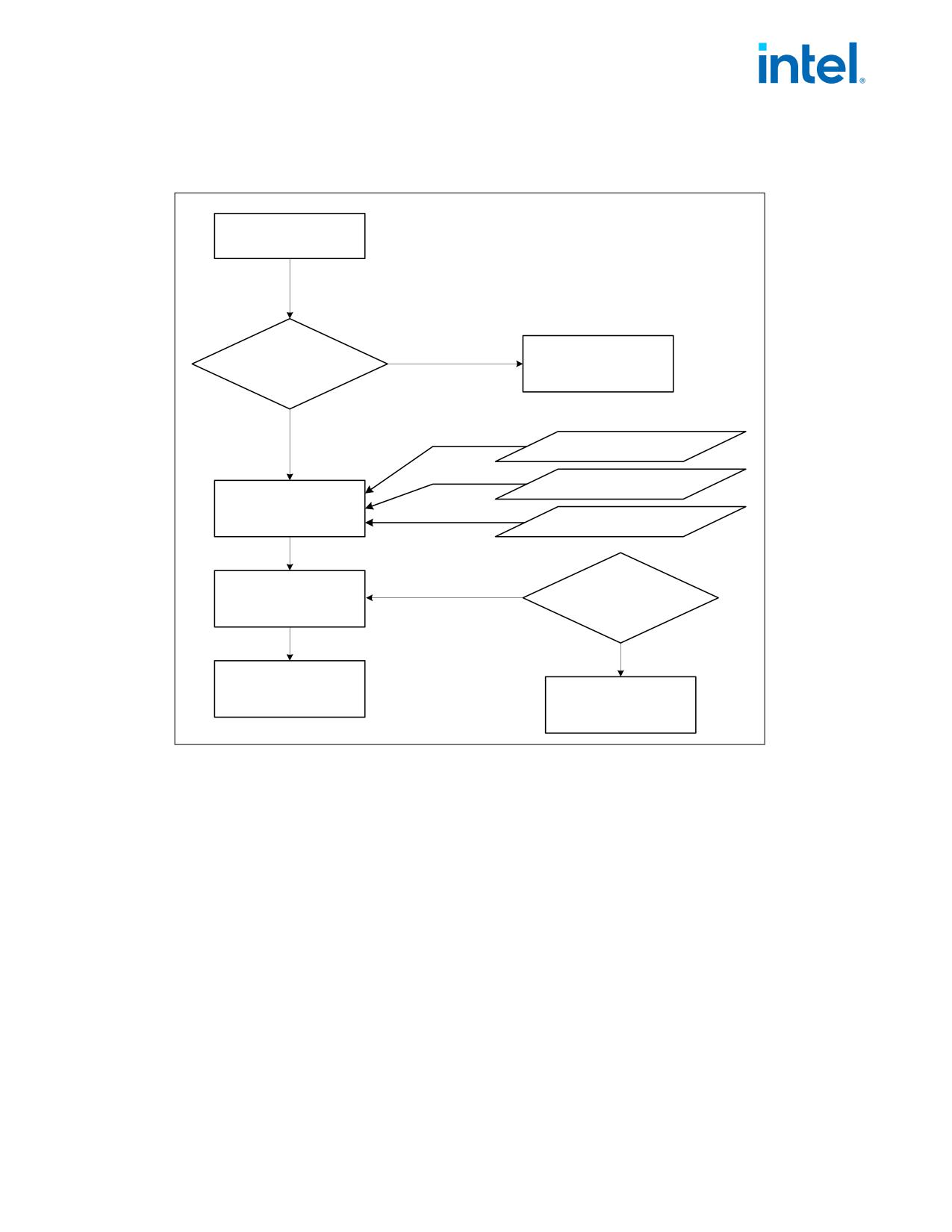
Figure 1-5 provides an algorithm which software can use to extract the maximum processor operating frequency
from the processor brand string.
Scan "Brand String" in
Reverse Byte Order
"zHM", or
Match
"zHG", or
Substring
"zHT"
False
IF Substring Matched
Report Error
If "zHM"
True
Multiplier = 1 x 10⁶
If "zHG"
Multiplier = 1 x 10⁹
Determine "Multiplier"
If "zHT"
Multiplier = 1 x 10¹²
Scan Digits
Until Blank
Reverse Digits
Determine "Freq"
To Decimal Value
In Reverse Order
Max. Qualified
Frequency =
"Freq" = X.YZ if
"Freq" x "Multiplier"
Digits = "ZY.X"
Figure 1-5. Algorithm for Extracting Maximum Processor Frequency
NOTE
When a frequency is given in a brand string, it is the maximum qualified frequency of the processor,
not the frequency at which the processor is currently running.
The Processor Brand Index Method
The brand index method (introduced with Pentium® III Xeon® processors) provides an entry point into a brand
identification table that is maintained in memory by system software and is accessible from system- and user-level
code. In this table, each brand index is associate with an ASCII brand identification string that identifies the official
Intel family and model number of a processor.
When CPUID executes with EAX set to 01H, the processor returns a brand index to the low byte in EBX. Software
can then use this index to locate the brand identification string for the processor in the brand identification table.
The first entry (brand index 0) in this table is reserved, allowing for backward compatibility with processors that do
not support the brand identification feature. Starting with processor signature family ID = 0FH, model = 03H,
brand index method is no longer supported. Use brand string method instead.
Table 1-9 shows brand indices that have identification strings associated with them.
Document Number: 319433-050
1-45

FUTURE INTEL® ARCHITECTURE INSTRUCTION EXTENSIONS AND FEATURES
Table 1-9. Mapping of Brand Indices; and Intel 64 and IA-32 Processor Brand Strings
Brand Index
Brand String
00H
This processor does not support the brand identification feature
01H
Intel(R) Celeron(R) processor1
02H
Intel(R) Pentium(R) III processor1
03H
Intel(R) Pentium(R) III Xeon(R) processor; If processor signature = 000006B1h, then Intel(R) Celeron(R)
processor
04H
Intel(R) Pentium(R) III processor
06H
Mobile Intel(R) Pentium(R) III processor-M
07H
Mobile Intel(R) Celeron(R) processor1
08H
Intel(R) Pentium(R) 4 processor
09H
Intel(R) Pentium(R) 4 processor
0AH
Intel(R) Celeron(R) processor1
0BH
Intel(R) Xeon(R) processor; If processor signature = 00000F13h, then Intel(R) Xeon(R) processor MP
0CH
Intel(R) Xeon(R) processor MP
0EH
Mobile Intel(R) Pentium(R) 4 processor-M; If processor signature = 00000F13h, then Intel(R) Xeon(R) processor
0FH
Mobile Intel(R) Celeron(R) processor1
11H
Mobile Genuine Intel(R) processor
12H
Intel(R) Celeron(R) M processor
13H
Mobile Intel(R) Celeron(R) processor1
14H
Intel(R) Celeron(R) processor
15H
Mobile Genuine Intel(R) processor
16H
Intel(R) Pentium(R) M processor
17H
Mobile Intel(R) Celeron(R) processor1
18H - 0FFH
RESERVED
NOTES:
1.Indicates versions of these processors that were introduced after the Pentium III.
IA-32 Architecture Compatibility
CPUID is not supported in early models of the Intel486 processor or in any IA-32 processor earlier than the
Intel486 processor.
Operation
IA32_BIOS_SIGN_ID MSR := Update with installed microcode revision number;
CASE (EAX) OF
EAX = 0:
EAX := Highest basic function input value understood by CPUID;
EBX := Vendor identification string;
EDX := Vendor identification string;
ECX := Vendor identification string;
BREAK;
EAX = 1H:
EAX[3:0] := Stepping ID;
EAX[7:4] := Model;
1-46
Document Number: 319433-050
FUTURE INTEL® ARCHITECTURE INSTRUCTION EXTENSIONS AND FEATURES
EAX[11:8] := Family;
EAX[13:12] := Processor type;
EAX[15:14] := Reserved;
EAX[19:16] := Extended Model;
EAX[27:20] := Extended Family;
EAX[31:28] := Reserved;
EBX[7:0] := Brand Index; (* Reserved if the value is zero. *)
EBX[15:8] := CLFLUSH Line Size;
EBX[16:23] := Reserved; (* Number of threads enabled = 2 if MT enable fuse set. *)
EBX[24:31] := Initial APIC ID;
ECX := Feature flags; (* See Figure 1-2. *)
EDX := Feature flags; (* See Figure 1-3. *)
BREAK;
EAX = 2H:
EAX := Cache and TLB information;
EBX := Cache and TLB information;
ECX := Cache and TLB information;
EDX := Cache and TLB information;
BREAK;
EAX = 3H:
EAX := Reserved;
EBX := Reserved;
ECX := ProcessorSerialNumber[31:0];
(* Pentium III processors only, otherwise reserved. *)
EDX := ProcessorSerialNumber[63:32];
(* Pentium III processors only, otherwise reserved. *
BREAK
EAX = 4H:
EAX := Deterministic Cache Parameters Leaf; (* See Table 1-3. *)
EBX := Deterministic Cache Parameters Leaf;
ECX := Deterministic Cache Parameters Leaf;
EDX := Deterministic Cache Parameters Leaf;
BREAK;
EAX = 5H:
EAX := MONITOR/MWAIT Leaf; (* See Table 1-3. *)
EBX := MONITOR/MWAIT Leaf;
ECX := MONITOR/MWAIT Leaf;
EDX := MONITOR/MWAIT Leaf;
BREAK;
EAX = 6H:
EAX := Thermal and Power Management Leaf; (* See Table 1-3. *)
EBX := Thermal and Power Management Leaf;
ECX := Thermal and Power Management Leaf;
EDX := Thermal and Power Management Leaf;
BREAK;
EAX = 7H:
EAX := Structured Extended Feature Leaf; (* See Table 1-3. *);
EBX := Structured Extended Feature Leaf;
ECX := Structured Extended Feature Leaf;
EDX := Structured Extended Feature Leaf;
BREAK;
EAX = 8H:
EAX := Reserved = 0;
EBX := Reserved = 0;
Document Number: 319433-050
1-47
FUTURE INTEL® ARCHITECTURE INSTRUCTION EXTENSIONS AND FEATURES
ECX := Reserved = 0;
EDX := Reserved = 0;
BREAK;
EAX = 9H:
EAX := Direct Cache Access Information Leaf; (* See Table 1-3. *)
EBX := Direct Cache Access Information Leaf;
ECX := Direct Cache Access Information Leaf;
EDX := Direct Cache Access Information Leaf;
BREAK;
EAX = AH:
EAX := Architectural Performance Monitoring Leaf; (* See Table 1-3. *)
EBX := Architectural Performance Monitoring Leaf;
ECX := Architectural Performance Monitoring Leaf;
EDX := Architectural Performance Monitoring Leaf;
BREAK
EAX = BH:
EAX := Extended Topology Enumeration Leaf; (* See Table 1-3. *)
EBX := Extended Topology Enumeration Leaf;
ECX := Extended Topology Enumeration Leaf;
EDX := Extended Topology Enumeration Leaf;
BREAK;
EAX = CH:
EAX := Reserved = 0;
EBX := Reserved = 0;
ECX := Reserved = 0;
EDX := Reserved = 0;
BREAK;
EAX = DH:
EAX := Processor Extended State Enumeration Leaf; (* See Table 1-3. *)
EBX := Processor Extended State Enumeration Leaf;
ECX := Processor Extended State Enumeration Leaf;
EDX := Processor Extended State Enumeration Leaf;
BREAK;
EAX = EH:
EAX := Reserved = 0;
EBX := Reserved = 0;
ECX := Reserved = 0;
EDX := Reserved = 0;
BREAK;
EAX = FH:
EAX := Platform Quality of Service Monitoring Enumeration Leaf; (* See Table 1-3. *)
EBX := Platform Quality of Service Monitoring Enumeration Leaf;
ECX := Platform Quality of Service Monitoring Enumeration Leaf;
EDX := Platform Quality of Service Monitoring Enumeration Leaf;
BREAK;
EAX = 10H:
EAX := Platform Quality of Service Enforcement Enumeration Leaf; (* See Table 1-3. *)
EBX := Platform Quality of Service Enforcement Enumeration Leaf;
ECX := Platform Quality of Service Enforcement Enumeration Leaf;
EDX := Platform Quality of Service Enforcement Enumeration Leaf;
BREAK;
EAX = 12H:
EAX := Intel SGX Enumeration Leaf; (* See Table 1-3. *)
EBX := Intel SGX Enumeration Leaf;
1-48
Document Number: 319433-050
FUTURE INTEL® ARCHITECTURE INSTRUCTION EXTENSIONS AND FEATURES
ECX := Intel SGX Enumeration Leaf;
EDX := Intel SGX Enumeration Leaf;
BREAK;
EAX = 14H:
EAX := Intel Processor Trace Enumeration Leaf; (* See Table 1-3. *)
EBX := Intel Processor Trace Enumeration Leaf;
ECX := Intel Processor Trace Enumeration Leaf;
EDX := Intel Processor Trace Enumeration Leaf;
BREAK;
EAX = 15H:
EAX := Time Stamp Counter and Core Crystal Clock Information Leaf; (* See Table 1-3. *)
EBX := Time Stamp Counter and Core Crystal Clock Information Leaf;
ECX := Time Stamp Counter and Core Crystal Clock Information Leaf;
EDX := Time Stamp Counter and Core Crystal Clock Information Leaf;
BREAK;
EAX = 16H:
EAX := Processor Frequency Information Enumeration Leaf; (* See Table 1-3. *)
EBX := Processor Frequency Information Enumeration Leaf;
ECX := Processor Frequency Information Enumeration Leaf;
EDX := Processor Frequency Information Enumeration Leaf;
BREAK;
EAX = 17H:
EAX := System-On-Chip Vendor Attribute Enumeration Leaf; (* See Table 1-3. *)
EBX := System-On-Chip Vendor Attribute Enumeration Leaf;
ECX := System-On-Chip Vendor Attribute Enumeration Leaf;
EDX := System-On-Chip Vendor Attribute Enumeration Leaf;
BREAK;
EAX = 18H:
EAX := Deterministic Address Translation Parameters Enumeration Leaf; (* See Table 1-3. *)
EBX := Deterministic Address Translation Parameters Enumeration Leaf;
ECX :=Deterministic Address Translation Parameters Enumeration Leaf;
EDX := Deterministic Address Translation Parameters Enumeration Leaf;
BREAK;
EAX = 19H:
EAX := Key Locker Enumeration Leaf; (* See Table 1-3. *)
EBX := Key Locker Enumeration Leaf;
ECX := Key Locker Enumeration Leaf;
EDX := Key Locker Enumeration Leaf;
BREAK;
EAX = 1AH:
EAX := Hybrid Information Enumeration Leaf; (* See Table 1-3. *)
EBX := Hybrid Information Enumeration Leaf;
ECX := Hybrid Information Enumeration Leaf;
EDX := Hybrid Information Enumeration Leaf;
BREAK;
EAX = 1BH:
EAX := PCONFIG Information Enumeration Leaf; (* See Table 1-3. *)
EBX := PCONFIG Information Enumeration Leaf;
ECX := PCONFIG Information Enumeration Leaf;
EDX := PCONFIG Information Enumeration Leaf;
BREAK;
EAX = 1CH:
EAX := Last Branch Record Information Enumeration Leaf; (* See Table 1-3. *)
EBX := Last Branch Record Information Enumeration Leaf;
Document Number: 319433-050
1-49
FUTURE INTEL® ARCHITECTURE INSTRUCTION EXTENSIONS AND FEATURES
ECX := Last Branch Record Information Enumeration Leaf;
EDX := Last Branch Record Information Enumeration Leaf;
BREAK;
EAX = 1DH:
EAX := Tile Information Enumeration Leaf; (* See Table 1-3. *)
EBX := Tile Information Enumeration Leaf;
ECX := Tile Information Enumeration Leaf;
EDX := Tile Information Enumeration Leaf;
BREAK;
EAX = 1EH:
EAX := TMUL Information Enumeration Leaf; (* See Table 1-3. *)
EBX := TMUL Information Enumeration Leaf;
ECX := TMUL Information Enumeration Leaf;
EDX := TMUL Information Enumeration Leaf;
BREAK;
EAX = 1FH:
EAX := V2 Extended Topology Enumeration Leaf; (* See Table 1-3. *)
EBX := V2 Extended Topology Enumeration Leaf;
ECX := V2 Extended Topology Enumeration Leaf;
EDX := V2 Extended Topology Enumeration Leaf;
BREAK;
EAX = 20H:
EAX := Processor History Reset Enumeration Leaf; (* See Table 1-3. *)
EBX := Processor History Reset Enumeration Leaf;
ECX := Processor History Reset Enumeration Leaf;
EDX := Processor History Reset Enumeration Leaf;
BREAK;
EAX = 23H:
EAX := Architectural Performance Monitoring Extended Leaf; (* See Table 1-3. *)
EBX := Architectural Performance Monitoring Extended Leaf;
ECX := Architectural Performance Monitoring Extended Leaf;
EDX := Architectural Performance Monitoring Extended Leaf;
BREAK;
EAX = 80000000H:
EAX := Highest extended function input value understood by CPUID;
EBX := Reserved;
ECX := Reserved;
EDX := Reserved;
BREAK;
EAX = 80000001H:
EAX := Reserved;
EBX := Reserved;
ECX := Extended Feature Bits (* See Table 1-3.*);
EDX := Extended Feature Bits (* See Table 1-3. *);
BREAK;
EAX = 80000002H:
EAX := Processor Brand String;
EBX := Processor Brand String, continued;
ECX := Processor Brand String, continued;
EDX := Processor Brand String, continued;
BREAK;
EAX = 80000003H:
EAX := Processor Brand String, continued;
EBX := Processor Brand String, continued;
1-50
Document Number: 319433-050
FUTURE INTEL® ARCHITECTURE INSTRUCTION EXTENSIONS AND FEATURES
ECX := Processor Brand String, continued;
EDX := Processor Brand String, continued;
BREAK;
EAX = 80000004H:
EAX := Processor Brand String, continued;
EBX := Processor Brand String, continued;
ECX := Processor Brand String, continued;
EDX := Processor Brand String, continued;
BREAK;
EAX = 80000005H:
EAX := Reserved = 0;
EBX := Reserved = 0;
ECX := Reserved = 0;
EDX := Reserved = 0;
BREAK;
EAX = 80000006H:
EAX := Reserved = 0;
EBX := Reserved = 0;
ECX := Cache information;
EDX := Reserved = 0;
BREAK;
EAX = 80000007H:
EAX := Reserved = 0;
EBX := Reserved = 0;
ECX := Reserved = 0;
EDX := Reserved = Miscellaneous feature flags;
BREAK;
EAX = 80000008H:
EAX := Address size information;
EBX := Miscellaneous feature flags;
ECX := Reserved = 0;
EDX := Reserved = 0;
BREAK;
DEFAULT: (* EAX = Value outside of recognized range for CPUID. *)
(* If the highest basic information leaf data depend on ECX input value, ECX is honored.*)
EAX := Reserved; (* Information returned for highest basic information leaf. *)
EBX := Reserved; (* Information returned for highest basic information leaf. *)
ECX := Reserved; (* Information returned for highest basic information leaf. *)
EDX := Reserved; (* Information returned for highest basic information leaf. *)
BREAK;
ESAC;
Flags Affected
None.
Exceptions (All Operating Modes)
#UD
If the LOCK prefix is used.
In earlier IA-32 processors that do not support the CPUID instruction, execution of the instruction results in an
invalid opcode (#UD) exception being generated.§
Document Number: 319433-050
1-51

FUTURE INTEL® ARCHITECTURE INSTRUCTION EXTENSIONS AND FEATURES
1.6
COMPRESSED DISPLACEMENT (DISP8*N) SUPPORT IN EVEX
For memory addressing using disp8 form, EVEX-encoded instructions always use a compressed displacement
scheme by multiplying disp8 in conjunction with a scaling factor N that is determined based on the vector length,
the value of EVEX.b bit (embedded broadcast) and the input element size of the instruction. In general, the factor
N corresponds to the number of bytes characterizing the internal memory operation of the input operand (e.g., 64
when the accessing a full 512-bit memory vector). The scale factor N is listed in Table 1-10 and Table 1-11 below,
where EVEX encoded instructions are classified using the tupletype attribute. The scale factor N of each tupletype
is listed based on the vector length (VL) and other factors affecting it.
Table 1-10 covers EVEX-encoded instructions which has a load semantic in conjunction with additional computa-
tional or data element movement operation, operating either on the full vector or half vector (due to conversion of
numerical precision from a wider format to narrower format). EVEX.b is supported for such instructions for data
element sizes which are either dword or qword.
EVEX-encoded instruction that are pure load/store, and “Load+op” instruction semantic that operate on data
element size less then dword do not support broadcasting using EVEX.b. These are listed in Table 1-11. Table 1-11
also includes many broadcast instructions which perform broadcast using a subset of data elements without using
EVEX.b. These instructions and a few data element size conversion instruction are covered in Table 1-11. Instruc-
tion classified in Table 1-11 do not use EVEX.b and EVEX.b must be 0, otherwise #UD will occur.
The tupletype will be referenced in the instruction operand encoding table in the reference page of each instruction,
providing the cross reference for the scaling factor N to encoding memory addressing operand.
Note that the disp8*N rules still apply when using 16b addressing.
Table 1-10. Compressed Displacement (DISP8*N) Affected by Embedded Broadcast
TupleType
EVEX.b
InputSize
EVEX.W
Broadcast
N (VL=128)
N (VL=256)
N (VL= 512)
Comment
0
32bit
0
none
16
32
64
Load+Op
(Full Vector
1
32bit
0
{1tox}
4
4
4
Full
Dword/Qword)
0
64bit
1
none
16
32
64
1
64bit
1
{1tox}
8
8
8
0
32bit
0
none
8
16
32
Load+Op
Half
(Half Vector)
1
32bit
0
{1tox}
4
4
4
Table 1-11. EVEX DISP8*N for Instructions Not Affected by Embedded Broadcast
TupleType
InputSize
EVEX.W
N (VL= 128)
N (VL= 256)
N (VL= 512)
Comment
Full Mem
N/A
N/A
16
32
64
Load/store or subDword full vector
8bit
N/A
1
1
1
1Tuple
16bit
N/A
2
2
2
Tuple1 Scalar
32bit
0
4
4
4
64bit
1
8
8
8
32bit
N/A
4
4
4
1 Tuple, memsize not affected by
Tuple1 Fixed
EVEX.W
64bit
N/A
8
8
8
Tuple1_4X
32bit
0
161
N/A
16
4FMA(PS)
32bit
0
8
8
8
Broadcast (2 elements)
Tuple2
64bit
1
NA
16
16
32bit
0
NA
16
16
Broadcast (4 elements)
Tuple4
64bit
1
NA
NA
32
Tuple8
32bit
0
NA
NA
32
Broadcast (8 elements)
Half Mem
N/A
N/A
8
16
32
SubQword Conversion
1-52
Document Number: 319433-050
FUTURE INTEL® ARCHITECTURE INSTRUCTION EXTENSIONS AND FEATURES
Table 1-11. EVEX DISP8*N for Instructions Not Affected by Embedded Broadcast(Continued)
TupleType
InputSize
EVEX.W
N (VL= 128)
N (VL= 256)
N (VL= 512)
Comment
Quarter Mem
N/A
N/A
4
8
16
SubDword Conversion
Eighth Mem
N/A
N/A
2
4
8
SubWord Conversion
Mem128
N/A
N/A
16
16
16
Shift count from memory
MOVDDUP
N/A
N/A
8
32
64
VMOVDDUP
NOTES:
1. Scalar.
1.7
BFLOAT16 FLOATING-POINT FORMAT
Intel® Deep Learning Boost (Intel® DL Boost) uses bfloat16 format (BF16). Figure 1-6 illustrates BF16 versus FP16
and FP32.
FP32
s
8 bit exp
23 bit mantissa
FP16
s
5 bit exp
10 bit mantissa
BF16
s
8 bit exp
7 bit mantissa
BFP10001
Figure 1-6. Comparison of BF16 to FP16 and FP32
BF16 has several advantages over FP16:
• It can be seen as a short version of FP32, skipping the least significant 16 bits of mantissa.
• There is no need to support denormals; FP32, and therefore also BF16, offer more than enough range
for deep learning training tasks.
• FP32 accumulation after the multiply is essential to achieve sufficient numerical behavior on an
application level.
• Hardware exception handling is not needed as this is a performance optimization; industry is designing
algorithms around checking inf/NaN.
Document Number: 319433-050
1-53
FUTURE INTEL® ARCHITECTURE INSTRUCTION EXTENSIONS AND FEATURES
1-54
Document Number: 319433-050
INSTRUCTION SET REFERENCE, A-Z
CHAPTER 2
INSTRUCTION SET REFERENCE, A-Z
Instructions described in this document follow the general documentation convention established in the Intel® 64
and IA-32 Architectures Software Developer’s Manual Volume 2A. Additionally, some instructions use notation
conventions as described below.
In the instruction encoding, the MODRM byte is represented several ways depending on the role it plays. The
MODRM byte has 3 fields: 2-bit MODRM.MOD field, a 3-bit MODRM.REG field and a 3-bit MODRM.RM field. When all
bits of the MODRM byte have fixed values for an instruction, the 2-hex nibble value of that byte is presented after
the opcode in the encoding boxes on the instruction description pages. When only some fields of the MODRM byte
must contain fixed values, those values are specified as follows:
• If only the MODRM.MOD must be 0b11, and MODRM.REG and MODRM.RM fields are unrestricted, this is
denoted as 11:rrr:bbb. The rrr correspond to the 3-bits of the MODRM.REG field and the bbb correspond to
the 3-bits of the MODMR.RM field.
• If the MODRM.MOD field is constrained to be a value other than 0b11, i.e., it must be one of 0b00, 0b01, or
0b10, then we use the notation !(11).
• If for example only the MODRM.REG field had a specific required value, e.g., 0b101, that would be denoted as
mm:101:bbb.
NOTE
Historically the Intel® 64 and IA-32 Architectures Software Developer’s Manual only specified the
MODRM.REG field restrictions with the notation /0 ... /7 and did not specify restrictions on the
MODRM.MOD and MODRM.RM fields in the encoding boxes.
2.1
INSTRUCTION SET REFERENCE
Document Number: 319433-050
2-1
INSTRUCTION SET REFERENCE, A-Z
AADD-Atomically Add
Opcode/
Op/
64/32 bit
CPUID Feature
Description
Instruction
En
Mode
Flag
Support
NP 0F38 FC !(11):rrr:bbb
A
V/V
RAO-INT
Atomically add my with ry and store the result in
my.
AADD my, ry
Instruction Operand Encoding
Op/En
Operand 1
Operand 2
Operand 3
Operand 4
A
ModRM:r/m (r, w)
ModRM:reg (r)
N/A
N/A
Description
This instruction atomically adds the destination operand (first operand) and the source operand (second operand),
and then stores the result in the destination operand.
The destination operand is a memory location and the source operand is a register. In 64-bit mode, the instruction’s
default operation size is 32 bits. Using a REX prefix in the form of REX.R permits access to additional registers (R8-
R15). Using a REX prefix in the form of REX.W promotes operation to 64 bits. The destination operand must be
naturally aligned with respect to the data size, at a 4-byte boundary, or an 8-byte boundary if used with a REX.W
prefix in 64-bit mode.
This instruction requires that the destination operand has a write-back (WB) memory type and it is implemented
using the weakly-ordered memory consistency model of write combining (WC) memory type. Before the operation,
the cache line is written-back (if modified) and invalidated from the processor cache. When the operation
completes, the processor may optimize the cacheability of the destination address by writing the result only to
specific levels of the cache hierarchy. Because this instructions uses a weakly-ordered memory consistency model,
a fencing operation implemented with LFENCE, SFENCE, or MFENCE instruction should be used in conjunction with
AADD if a stronger ordering is required. However, note that AADD is not ordered with respect to a younger LFENCE,
as this instruction is not loading data from memory into the processor.
Any attempt to execute the AADD instruction inside an Intel TSX transaction will result in a transaction abort.
Operation
AADD dest, src
dest := dest + src;
Flags Affected
None.
Protected Mode Exceptions
#GP(0)
For an illegal memory operand effective address in the CS, DS, ES, FS or GS segments.
If the memory address is not naturally aligned to the operand size.
If the memory address memory type is not write-back (WB).
#SS(0)
For an illegal address in the SS segment.
#PF(fault-code)
If a page fault occurs.
#UD
If the LOCK prefix is used.
If CPUID.(EAX=07H, ECX=01H):EAX.RAO-INT[bit 3] = 0.
Real-Address Mode Exceptions
#GP
If any part of the operand lies outside the effective address space from 0 to FFFFH.
If the memory address is not naturally aligned to the operand size.
2-2
Document Number: 319433-050
INSTRUCTION SET REFERENCE, A-Z
If the memory address memory type is not write-back (WB).
#SS
For an illegal address in the SS segment.
#UD
If the LOCK prefix is used.
If CPUID.(EAX=07H, ECX=01H):EAX.RAO-INT[bit 3] = 0.
Virtual-8086 Mode Exceptions
Same exceptions as in protected mode.
Compatibility Mode Exceptions
Same exceptions as in protected mode.
64-Bit Mode Exceptions
#GP(0)
If the memory address is in a non-canonical form.
If the memory address is not naturally aligned to the operand size.
If the memory address memory type is not write-back (WB).
#SS(0)
If a memory address referencing the SS segment is in a non-canonical form.
#PF(fault-code)
If a page fault occurs.
#UD
If the LOCK prefix is used.
If CPUID.(EAX=07H, ECX=01H):EAX.RAO-INT[bit 3] = 0.
Document Number: 319433-050
2-3
INSTRUCTION SET REFERENCE, A-Z
AAND-Atomically AND
Opcode/
Op/
64/32 bit
CPUID Feature
Description
Instruction
En
Mode
Flag
Support
66 0F38 FC !(11):rrr:bbb
A
V/V
RAO-INT
Atomically AND my with ry and store the result in
my.
AAND my, ry
Instruction Operand Encoding
Op/En
Operand 1
Operand 2
Operand 3
Operand 4
A
ModRM:r/m (r, w)
ModRM:reg (r)
N/A
N/A
Description
This instruction atomically performs a bitwise AND operation of the destination operand (first operand) and the
source operand (second operand), and then stores the result in the destination operand.
The destination operand is a memory location and the source operand is a register. In 64-bit mode, the instruction’s
default operation size is 32 bits. Using a REX prefix in the form of REX.R permits access to additional registers (R8-
R15). Using a REX prefix in the form of REX.W promotes operation to 64 bits. The destination operand must be
naturally aligned with respect to the data size, at a 4-byte boundary, or an 8-byte boundary if used with a REX.W
prefix in 64-bit mode.
This instruction requires that the destination operand has a write-back (WB) memory type and it is implemented
using the weakly-ordered memory consistency model of write combining (WC) memory type. Before the operation,
the cache line is written-back (if modified) and invalidated from the processor cache. When the operation
completes, the processor may optimize the cacheability of the destination address by writing the result only to
specific levels of the cache hierarchy. Because this instructions uses a weakly-ordered memory consistency model,
a fencing operation implemented with LFENCE, SFENCE, or MFENCE instruction should be used in conjunction with
AAND if a stronger ordering is required. However, note that AAND is not ordered with respect to a younger LFENCE,
as this instruction is not loading data from memory into the processor.
Any attempt to execute the AAND instruction inside an Intel TSX transaction will result in a transaction abort.
Operation
AAND dest, src
dest := dest AND src;
Flags Affected
None.
Protected Mode Exceptions
#GP(0)
For an illegal memory operand effective address in the CS, DS, ES, FS or GS segments.
If the memory address is not naturally aligned to the operand size.
If the memory address memory type is not write-back (WB).
#SS(0)
For an illegal address in the SS segment.
#PF(fault-code)
If a page fault occurs.
#UD
If the LOCK prefix is used.
If CPUID.(EAX=07H, ECX=01H):EAX.RAO-INT[bit 3] = 0.
2-4
Document Number: 319433-050
INSTRUCTION SET REFERENCE, A-Z
Real-Address Mode Exceptions
#GP
If any part of the operand lies outside the effective address space from 0 to FFFFH.
If the memory address is not naturally aligned to the operand size.
If the memory address memory type is not write-back (WB).
#SS
For an illegal address in the SS segment.
#UD
If the LOCK prefix is used.
If CPUID.(EAX=07H, ECX=01H):EAX.RAO-INT[bit 3] = 0.
Virtual-8086 Mode Exceptions
Same exceptions as in protected mode.
Compatibility Mode Exceptions
Same exceptions as in protected mode.
64-Bit Mode Exceptions
#GP(0)
If the memory address is in a non-canonical form.
If the memory address is not naturally aligned to the operand size.
If the memory address memory type is not write-back (WB).
#SS(0)
If a memory address referencing the SS segment is in a non-canonical form.
#PF(fault-code)
If a page fault occurs.
#UD
If the LOCK prefix is used.
If CPUID.(EAX=07H, ECX=01H):EAX.RAO-INT[bit 3] = 0.
Document Number: 319433-050
2-5
INSTRUCTION SET REFERENCE, A-Z
AOR-Atomically OR
Opcode/
Op/
64/32 bit
CPUID Feature
Description
Instruction
En
Mode
Flag
Support
F2 0F38 FC !(11):rrr:bbb
A
V/V
RAO-INT
Atomically OR my with ry and store the result in
my.
AOR my, ry
Instruction Operand Encoding
Op/En
Operand 1
Operand 2
Operand 3
Operand 4
A
ModRM:r/m (r, w)
ModRM:reg (r)
N/A
N/A
Description
This instruction atomically performs a bitwise OR operation of the destination operand (first operand) and the
source operand (second operand), and then stores the result in the destination operand.
The destination operand is a memory location and the source operand is a register. In 64-bit mode, the instruction’s
default operation size is 32 bits. Using a REX prefix in the form of REX.R permits access to additional registers (R8-
R15). Using a REX prefix in the form of REX.W promotes operation to 64 bits. The destination operand must be
naturally aligned with respect to the data size, at a 4-byte boundary, or an 8-byte boundary if used with a REX.W
prefix in 64-bit mode.
This instruction requires that the destination operand has a write-back (WB) memory type and it is implemented
using the weakly-ordered memory consistency model of write combining (WC) memory type. Before the operation,
the cache line is written-back (if modified) and invalidated from the processor cache. When the operation
completes, the processor may optimize the cacheability of the destination address by writing the result only to
specific levels of the cache hierarchy. Because this instructions uses a weakly-ordered memory consistency model,
a fencing operation implemented with LFENCE, SFENCE, or MFENCE instruction should be used in conjunction with
AOR if a stronger ordering is required. However, note that AOR is not ordered with respect to a younger LFENCE, as
this instruction is not loading data from memory into the processor.
Any attempt to execute the AOR instruction inside an Intel TSX transaction will result in a transaction abort.
Operation
AOR dest, src
dest := dest OR src;
Flags Affected
None.
Protected Mode Exceptions
#GP(0)
For an illegal memory operand effective address in the CS, DS, ES, FS or GS segments.
If the memory address is not naturally aligned to the operand size.
If the memory address memory type is not write-back (WB).
#SS(0)
For an illegal address in the SS segment.
#PF(fault-code)
If a page fault occurs.
#UD
If the LOCK prefix is used.
If CPUID.(EAX=07H, ECX=01H):EAX.RAO-INT[bit 3] = 0.
2-6
Document Number: 319433-050
INSTRUCTION SET REFERENCE, A-Z
Real-Address Mode Exceptions
#GP
If any part of the operand lies outside the effective address space from 0 to FFFFH.
If the memory address is not naturally aligned to the operand size.
If the memory address memory type is not write-back (WB).
#SS
For an illegal address in the SS segment.
#UD
If the LOCK prefix is used.
If CPUID.(EAX=07H, ECX=01H):EAX.RAO-INT[bit 3] = 0.
Virtual-8086 Mode Exceptions
Same exceptions as in protected mode.
Compatibility Mode Exceptions
Same exceptions as in protected mode.
64-Bit Mode Exceptions
#GP(0)
If the memory address is in a non-canonical form.
If the memory address is not naturally aligned to the operand size.
If the memory address memory type is not write-back (WB).
#SS(0)
If a memory address referencing the SS segment is in a non-canonical form.
#PF(fault-code)
If a page fault occurs.
#UD
If the LOCK prefix is used.
If CPUID.(EAX=07H, ECX=01H):EAX.RAO-INT[bit 3] = 0.
Document Number: 319433-050
2-7
INSTRUCTION SET REFERENCE, A-Z
AXOR-Atomically XOR
Opcode/
Op/
64/32 bit
CPUID Feature
Description
Instruction
En
Mode
Flag
Support
F3 0F38 FC !(11):rrr:bbb
A
V/V
RAO-INT
Atomically XOR my with ry and store the result in
my.
AXOR my, ry
Instruction Operand Encoding
Op/En
Operand 1
Operand 2
Operand 3
Operand 4
A
ModRM:r/m (r, w)
ModRM:reg (r)
N/A
N/A
Description
This instruction atomically performs a bitwise XOR operation of the destination operand (first operand) and the
source operand (second operand), and then stores the result in the destination operand.
The destination operand is a memory location and the source operand is a register. In 64-bit mode, the instruction’s
default operation size is 32 bits. Using a REX prefix in the form of REX.R permits access to additional registers (R8-
R15). Using a REX prefix in the form of REX.W promotes operation to 64 bits. The destination operand must be
naturally aligned with respect to the data size, at a 4-byte boundary, or an 8-byte boundary if used with a REX.W
prefix in 64-bit mode.
This instruction requires that the destination operand has a write-back (WB) memory type and it is implemented
using the weakly-ordered memory consistency model of write combining (WC) memory type. Before the operation,
the cache line is written-back (if modified) and invalidated from the processor cache. When the operation
completes, the processor may optimize the cacheability of the destination address by writing the result only to
specific levels of the cache hierarchy. Because this instructions uses a weakly-ordered memory consistency model,
a fencing operation implemented with LFENCE, SFENCE, or MFENCE instruction should be used in conjunction with
AXOR if a stronger ordering is required. However, note that AXOR is not ordered with respect to a younger LFENCE,
as this instruction is not loading data from memory into the processor.
Any attempt to execute the AXOR instruction inside an Intel TSX transaction will result in a transaction abort.
Operation
AXOR dest, src
dest := dest XOR src;
Flags Affected
None.
Protected Mode Exceptions
#GP(0)
For an illegal memory operand effective address in the CS, DS, ES, FS or GS segments.
If the memory address is not naturally aligned to the operand size.
If the memory address memory type is not write-back (WB).
#SS(0)
For an illegal address in the SS segment.
#PF(fault-code)
If a page fault occurs.
#UD
If the LOCK prefix is used.
If CPUID.(EAX=07H, ECX=01H):EAX.RAO-INT[bit 3] = 0.
2-8
Document Number: 319433-050
INSTRUCTION SET REFERENCE, A-Z
Real-Address Mode Exceptions
#GP
If any part of the operand lies outside the effective address space from 0 to FFFFH.
If the memory address is not naturally aligned to the operand size.
If the memory address memory type is not write-back (WB).
#SS
For an illegal address in the SS segment.
#UD
If the LOCK prefix is used.
If CPUID.(EAX=07H, ECX=01H):EAX.RAO-INT[bit 3] = 0.
Virtual-8086 Mode Exceptions
Same exceptions as in protected mode.
Compatibility Mode Exceptions
Same exceptions as in protected mode.
64-Bit Mode Exceptions
#GP(0)
If the memory address is in a non-canonical form.
If the memory address is not naturally aligned to the operand size.
If the memory address memory type is not write-back (WB).
#SS(0)
If a memory address referencing the SS segment is in a non-canonical form.
#PF(fault-code)
If a page fault occurs.
#UD
If the LOCK prefix is used.
If CPUID.(EAX=07H, ECX=01H):EAX.RAO-INT[bit 3] = 0.
Document Number: 319433-050
2-9

INSTRUCTION SET REFERENCE, A-Z
CMPccXADD-Compare and Add if Condition is Met
Opcode/
Op/
64/32 bit
CPUID Feature
Description
Instruction
En
Mode
Flag
Support
A
V/N.E.
CMPCCXADD
Compare value in r32 (second operand) with
VEX.128.66.0F38.W0 E6 !(11):rrr:bbb
value in m32. If below or equal (CF=1 or ZF=1),
CMPBEXADD m32, r32, r32
add value from r32 (third operand) to m32 and
write new value in m32. The second operand is
always updated with the original value from
m32.
A
V/N.E.
CMPCCXADD
Compare value in r64 (second operand) with
VEX.128.66.0F38.W1 E6 !(11):rrr:bbb
value in m64. If below or equal (CF=1 or ZF=1),
CMPBEXADD m64, r64, r64
add value from r64 (third operand) to m64 and
write new value in m64. The second operand is
always updated with the original value from
m64.
A
V/N.E.
CMPCCXADD
Compare value in r32 (second operand) with
VEX.128.66.0F38.W0 E2 !(11):rrr:bbb
value in m32. If below (CF=1), add value from
CMPBXADD m32, r32, r32
r32 (third operand) to m32 and write new value
in m32. The second operand is always updated
with the original value from m32.
A
V/N.E.
CMPCCXADD
Compare value in r64 (second operand) with
VEX.128.66.0F38.W1 E2 !(11):rrr:bbb
value in m64. If below (CF=1), add value from
CMPBXADD m64, r64, r64
r64 (third operand) to m64 and write new value
in m64. The second operand is always updated
with the original value from m64.
A
V/N.E.
CMPCCXADD
Compare value in r32 (second operand) with
VEX.128.66.0F38.W0 EE !(11):rrr:bbb
value in m32. If less or equal (ZF=1 or SF≠OF),
CMPLEXADD m32, r32, r32
add value from r32 (third operand) to m32 and
write new value in m32. The second operand is
always updated with the original value from
m32.
A
V/N.E.
CMPCCXADD
Compare value in r64 (second operand) with
VEX.128.66.0F38.W1 EE !(11):rrr:bbb
value in m64. If less or equal (ZF=1 or SF≠OF),
CMPLEXADD m64, r64, r64
add value from r64 (third operand) to m64 and
write new value in m64. The second operand is
always updated with the original value from
m64.
A
V/N.E.
CMPCCXADD
Compare value in r32 (second operand) with
VEX.128.66.0F38.W0 EC !(11):rrr:bbb
value in m32. If less (SF≠OF), add value from r32
CMPLXADD m32, r32, r32
(third operand) to m32 and write new value in
m32. The second operand is always updated
with the original value from m32.
VEX.128.66.0F38.W1 EC !(11):rrr:bbb
A
V/N.E.
CMPCCXADD
Compare value in r64 (second operand) with
value in m64. If less (SF≠OF), add value from r64
CMPLXADD m64, r64, r64
(third operand) to m64 and write new value in
m64. The second operand is always updated
with the original value from m64.
VEX.128.66.0F38.W0 E7 !(11):rrr:bbb
A
V/N.E.
CMPCCXADD
Compare value in r32 (second operand) with
value in m32. If not below or equal (CF=0 and
CMPNBEXADD m32, r32, r32
ZF=0), add value from r32 (third operand) to
m32 and write new value in m32. The second
operand is always updated with the original
value from m32.
2-10
Document Number: 319433-050

INSTRUCTION SET REFERENCE, A-Z
Opcode/
Op/
64/32 bit
CPUID Feature
Description
Instruction
En
Mode
Flag
Support
VEX.128.66.0F38.W1 E7 !(11):rrr:bbb
A
V/N.E.
CMPCCXADD
Compare value in r64 (second operand) with
value in m64. If not below or equal (CF=0 and
CMPNBEXADD m64, r64, r64
ZF=0), add value from r64 (third operand) to
m64 and write new value in m64. The second
operand is always updated with the original
value from m64.
VEX.128.66.0F38.W0 E3 !(11):rrr:bbb
A
V/N.E.
CMPCCXADD
Compare value in r32 (second operand) with
value in m32. If not below (CF=0), add value from
CMPNBXADD m32, r32, r32
r32 (third operand) to m32 and write new value
in m32. The second operand is always updated
with the original value from m32.
A
V/N.E.
CMPCCXADD
Compare value in r64 (second operand) with
VEX.128.66.0F38.W1 E3 !(11):rrr:bbb
value in m64. If not below (CF=0), add value from
CMPNBXADD m64, r64, r64
r64 (third operand) to m64 and write new value
in m64. The second operand is always updated
with the original value from m64.
A
V/N.E.
CMPCCXADD
Compare value in r32 (second operand) with
VEX.128.66.0F38.W0 EF !(11):rrr:bbb
value in m32. If not less or equal (ZF=0 and
CMPNLEXADD m32, r32, r32
SF=OF), add value from r32 (third operand) to
m32 and write new value in m32. The second
operand is always updated with the original
value from m32.
A
V/N.E.
CMPCCXADD
Compare value in r64 (second operand) with
VEX.128.66.0F38.W1 EF !(11):rrr:bbb
value in m64. If not less or equal (ZF=0 and
CMPNLEXADD m64, r64, r64
SF=OF), add value from r64 (third operand) to
m64 and write new value in m64. The second
operand is always updated with the original
value from m64.
A
V/N.E.
CMPCCXADD
Compare value in r32 (second operand) with
VEX.128.66.0F38.W0 ED !(11):rrr:bbb
value in m32. If not less (SF=OF), add value from
CMPNLXADD m32, r32, r32
r32 (third operand) to m32 and write new value
in m32. The second operand is always updated
with the original value from m32.
A
V/N.E.
CMPCCXADD
Compare value in r64 (second operand) with
VEX.128.66.0F38.W1 ED !(11):rrr:bbb
value in m64. If not less (SF=OF), add value from
CMPNLXADD m64, r64, r64
r64 (third operand) to m64 and write new value
in m64. The second operand is always updated
with the original value from m64.
A
V/N.E.
CMPCCXADD
Compare value in r32 (second operand) with
VEX.128.66.0F38.W0 E1 !(11):rrr:bbb
value in m32. If not overflow (OF=0), add value
CMPNOXADD m32, r32, r32
from r32 (third operand) to m32 and write new
value in m32. The second operand is always
updated with the original value from m32.
A
V/N.E.
CMPCCXADD
Compare value in r64 (second operand) with
VEX.128.66.0F38.W1 E1 !(11):rrr:bbb
value in m64. If not overflow (OF=0), add value
CMPNOXADD m64, r64, r64
from r64 (third operand) to m64 and write new
value in m64. The second operand is always
updated with the original value from m64.
Document Number: 319433-050
2-11

INSTRUCTION SET REFERENCE, A-Z
Opcode/
Op/
64/32 bit
CPUID Feature
Description
Instruction
En
Mode
Flag
Support
A
V/N.E.
CMPCCXADD
Compare value in r32 (second operand) with
VEX.128.66.0F38.W0 EB !(11):rrr:bbb
value in m32. If not parity (PF=0), add value from
CMPNPXADD m32, r32, r32
r32 (third operand) to m32 and write new value
in m32. The second operand is always updated
with the original value from m32.
A
V/N.E.
CMPCCXADD
Compare value in r64 (second operand) with
VEX.128.66.0F38.W1 EB !(11):rrr:bbb
value in m64. If not parity (PF=0), add value from
CMPNPXADD m64, r64, r64
r64 (third operand) to m64 and write new value
in m64. The second operand is always updated
with the original value from m64.
A
V/N.E.
CMPCCXADD
Compare value in r32 (second operand) with
VEX.128.66.0F38.W0 E9 !(11):rrr:bbb
value in m32. If not sign (SF=0), add value from
CMPNSXADD m32, r32, r32
r32 (third operand) to m32 and write new value
in m32. The second operand is always updated
with the original value from m32.
A
V/N.E.
CMPCCXADD
Compare value in r64 (second operand) with
VEX.128.66.0F38.W1 E9 !(11):rrr:bbb
value in m64. If not sign (SF=0), add value from
CMPNSXADD m64, r64, r64
r64 (third operand) to m64 and write new value
in m64. The second operand is always updated
with the original value from m64.
A
V/N.E.
CMPCCXADD
Compare value in r32 (second operand) with
VEX.128.66.0F38.W0 E5 !(11):rrr:bbb
value in m32. If not zero (ZF=0), add value from
CMPNZXADD m32, r32, r32
r32 (third operand) to m32 and write new value
in m32. The second operand is always updated
with the original value from m32.
A
V/N.E.
CMPCCXADD
Compare value in r64 (second operand) with
VEX.128.66.0F38.W1 E5 !(11):rrr:bbb
value in m64. If not zero (ZF=0), add value from
CMPNZXADD m64, r64, r64
r64 (third operand) to m64 and write new value
in m64. The second operand is always updated
with the original value from m64.
A
V/N.E.
CMPCCXADD
Compare value in r32 (second operand) with
VEX.128.66.0F38.W0 E0 !(11):rrr:bbb
value in m32. If overflow (OF=1), add value from
CMPOXADD m32, r32, r32
r32 (third operand) to m32 and write new value
in m32. The second operand is always updated
with the original value from m32.
A
V/N.E.
CMPCCXADD
Compare value in r64 (second operand) with
VEX.128.66.0F38.W1 E0 !(11):rrr:bbb
value in m64. If overflow (OF=1), add value from
CMPOXADD m64, r64, r64
r64 (third operand) to m64 and write new value
in m64. The second operand is always updated
with the original value from m64.
A
V/N.E.
CMPCCXADD
Compare value in r32 (second operand) with
VEX.128.66.0F38.W0 EA !(11):rrr:bbb
value in m32. If parity (PF=1), add value from
CMPPXADD m32, r32, r32
r32 (third operand) to m32 and write new value
in m32. The second operand is always updated
with the original value from m32.
A
V/N.E.
CMPCCXADD
Compare value in r64 (second operand) with
VEX.128.66.0F38.W1 EA !(11):rrr:bbb
value in m64. If parity (PF=1), add value from
CMPPXADD m64, r64, r64
r64 (third operand) to m64 and write new value
in m64. The second operand is always updated
with the original value from m64.
2-12
Document Number: 319433-050

INSTRUCTION SET REFERENCE, A-Z
Opcode/
Op/
64/32 bit
CPUID Feature
Description
Instruction
En
Mode
Flag
Support
A
V/N.E.
CMPCCXADD
Compare value in r32 (second operand) with
VEX.128.66.0F38.W0 E8 !(11):rrr:bbb
value in m32. If sign (SF=1), add value from r32
CMPSXADD m32, r32, r32
(third operand) to m32 and write new value in
m32. The second operand is always updated
with the original value from m32.
A
V/N.E.
CMPCCXADD
Compare value in r64 (second operand) with
VEX.128.66.0F38.W1 E8 !(11):rrr:bbb
value in m64. If sign (SF=1), add value from r64
CMPSXADD m64, r64, r64
(third operand) to m64 and write new value in
m64. The second operand is always updated
with the original value from m64.
A
V/N.E.
CMPCCXADD
Compare value in r32 (second operand) with
VEX.128.66.0F38.W0 E4 !(11):rrr:bbb
value in m32. If zero (ZF=1), add value from r32
CMPZXADD m32, r32, r32
(third operand) to m32 and write new value in
m32. The second operand is always updated
with the original value from m32.
A
V/N.E.
CMPCCXADD
Compare value in r64 (second operand) with
VEX.128.66.0F38.W1 E4 !(11):rrr:bbb
value in m64. If zero (ZF=1), add value from r64
CMPZXADD m64, r64, r64
(third operand) to m64 and write new value in
m64. The second operand is always updated
with the original value from m64.
Instruction Operand Encoding
Op/En
Tuple
Operand 1
Operand 2
Operand 3
Operand 4
A
N/A
ModRM:r/m (r, w)
ModRM:reg (r, w)
VEX.vvvv (r)
N/A
Description
This instruction compares the value from memory with the value of the second operand. If the specified condition
is met, then the processor will add the third operand to the memory operand and write it into memory, else the
memory is unchanged by this instruction.
This instruction must have MODRM.MOD equal to 0, 1, or 2. The value 3 for MODRM.MOD is reserved and will cause
an invalid opcode exception (#UD).
The second operand is always updated with the original value of the memory operand. The EFLAGS conditions are
updated from the results of the comparison.The instruction uses an implicit lock. This instruction does not permit
the use of an explicit lock prefix.
Operation
CMPCCXADD srcdest1, srcdest2, src3
tmp1 := load lock srcdest1
tmp2 := tmp1 + src3
EFLAGS.CS,OF,SF,ZF,AF,PF := CMP tmp1, srcdest2
IF <condition>:
srcdest1 := store unlock tmp2
ELSE
srcdest1 := store unlock tmp1
srcdest2 :=tmp1
Flags Affected
The EFLAGS conditions are updated from the results of the comparison.
Document Number: 319433-050
2-13

INSTRUCTION SET REFERENCE, A-Z
SIMD Floating-Point Exceptions
None.
Exceptions
Exceptions Type 14; see Table 2-1.
Table 2-1. Type 14 Class Exception Conditions
Exception
Cause of Exception
X
X
X
Only supported in 64-bit mode.
Invalid Opcode,
X
If any LOCK, REX, F2, F3, or 66 prefixes precede a VEX prefix.
#UD
X
If any corresponding CPUID feature flag is ‘0’.
If a memory address referencing the SS segment is in a non-canonical
Stack, #SS(0)
X
form.
General
X
If not naturally aligned (4/8 bytes).
Protection,
If the memory address is in a non-canonical form.
X
#GP(0)
Page Fault,
If a page fault occurs.
X
#PF(fault-code)
2-14
Document Number: 319433-050

INSTRUCTION SET REFERENCE, A-Z
PBNDKB-Platform Bind Key to Binary Large Object
Opcode/
Op/
64/32
CPUID Feature
Description
Instruction
En
bit Mode
Flag
Support
NP 0F 01 C7
ZO
V/I
PBNDKB
This instruction is used to bind information to a
platform by encrypting it with a platform-specific
PBNDKB
wrapping key.
Instruction Operand Encoding
Op/En
Operand 1
Operand 2
Operand 3
Operand 4
ZO
N/A
N/A
N/A
N/A
Description
The PBNDKB instruction allows software to bind information to a platform by encrypting it with a platform-specific
wrapping key. The encrypted data may later be used by the PCONFIG instruction to configure the total storage
encryption (TSE) engine.1
The instruction can be executed only in 64-bit mode. The registers RBX and RCX provide input information to the
instruction. Executions of PBNDKB may fail for platform-specific reasons. An execution reports failure by setting
the ZF flag and loading EAX with a non-zero failure reason; a successful execution clears ZF and EAX.
The instruction operates on 256-byte data structures called bind structures. It reads a bind structure at the linear
address in RBX and writes a modified bind structure to the linear address in RCX. The addresses in RBX and RCX
must be different from each other and must be 256-byte aligned.
The instruction encrypts a portion of the input bind structure and generates a MAC of parts of that structure. The
encrypted data and MAC are written out as part of the output bind structure.
The format of a bind structure is given in Table 2-1.
Table 2-1. Bind Structure Format
Field
Offset (bytes)
Size (bytes)
Comments
MAC
0
16
Output by PBNDKB as a MAC based on the input bind structure
Reserved
16
8
Reserved; must be zero on input, output as zero
IV
24
12
Initialization vector generated and output by PBNDKB
Reserved
36
28
Reserved; must be zero on input, output as zero
BTENCDATA
64
64
Encryption data (plaintext on input; ciphertext on output)
BTDATA
128
128
Additional control and data (modified but not encrypted)
A description of each of the fields in a bind structure is provided below:
• MAC: A MAC produced by PBNDKB of parts of its input bind structure. This field in the input bind structure is
not used.
• IV: PBNDKB randomly generates a 96-bit initialization vector and uses it as input to an authenticated
encryption function. The generated IV is written to the output bind structure. If there is insufficient entropy for
the random-number generator, PBNDKB will fail and report the failure by loading EAX with value 1 (ENTRO-
PY_ERROR). This field in the input bind structure is not used.
• BTENCDATA: In the input bind structure, the field contains the data to be encrypted. The data consist of two
256-bit keys, a data key and a tweak key. If the value of the KEY_GENERATION_CTRL field of the BTDATA (see
below) is 1, PBNDKB randomizes the values of these keys before encrypting them. (If there is insufficient
entropy for the random-number generator, PBNDKB will fail and report the failure by loading EAX with value 1
(ENTROPY_ERROR).) PBNDKB writes the encrypted data to this field in the output bind structure.
1.For details on Total Storage Encryption (TSE), see Chapter 11 of this document.
Document Number: 319433-050
2-15
INSTRUCTION SET REFERENCE, A-Z
• BTDATA: This field contains additional control and data that are not encrypted. It has the following format:
- USER_SUPP_CHALLENGE (bytes 31:0): PBNDKB uses this value in the input bind structure to determine
the wrapping key (see below). It writes zero to this field in the output bind structure.
- KEY_GENERATION_CTRL (byte 32): PBNDKB uses this value in the input bind structure to determine
whether to randomize the keys being encrypted. The value must be 0 or 1 (otherwise, a #GP occurs).
- The remaining 95 bytes are reserved and must be zero.
PBNDKB determines a 256-bit wrapping key by computing an HMAC based on SHA-256 using 256-bit platform-
specific key and the USER_SUPP_CHALLENGE in the BTDATA field in the input bind structure.
PBNDKB then uses the wrapping key and an AES GCM authenticated encryption function to encrypt BTENCDATA
and produce a MAC. The encryption function uses the following inputs:
• The 64-byte BTENCDATA to be encrypted (which may have been randomized; see above).
• The 256-bit wrapping key.
• The 96-bit IV randomly generated by PBNDKB.
•
176 bytes of additional authenticated data that are the concatenation of 8 bytes of zeroes, the IV, 28 bytes of
zeroes, and the BTDATA in the input bind structure.
• The length of the additional authenticated data (176).
The encryption function produces a structure with 64 bytes of encrypted data and a 16-byte MAC. PBNDKB saves
these values to the corresponding fields in its output bind structure. Other fields are copied from the input bind
structure or written as zero, except the IV (which receives the randomly generated value) and the
USER_SUPP_CHALLENGE in the BTDATA, which is written as zero.
Operation
(* #UD if PBNDKB is not enumerated, CPL > 0, or not in 64-bit mode*)
IF CPUID.(EAX=07H, ECX=01H):EBX.PBNDKB[bit 1] = 0 OR CPL > 0 OR not in 64-bit mode
THEN #UD; FI;
(* #GP if pointers are not aligned or overlapping *)
IF RBX = RCX OR RBX is not 256-byte aligned OR RCX is not 256-byte aligned
THEN #GP(0); FI;
Load TMP_BIND_STRUCT from 256 bytes at linear address in RBX;
(* Check TMP_BIND_STRUCT for illegal values *)
IF bytes 23:16 and bytes 63:36 of TMP_BIND_STRUCT are not all zero
THEN #GP(0); FI;
IF TMP_BIND_STRUCT.BTDATA.KEY_GENERATION_CTRL > 1
THEN #GP(0); FI;
IF bytes 127:33 of TMP_BIND_STRUCT.BTDATA are not all zero
THEN #GP(0); FI;
(* Randomize input keys if requested *)
IF TMP_BIND_STRUCT.BTDATA.KEY_GENERATION_CONTROL= 1
THEN
Load RNG_DATA_KEY with a random 256-bit value using hardware RNG;
Load RNG_TWEAK_KEY with a random 256-bit value using hardware RNG;
IF there was insufficient entropy
THEN (* PBNDKB failure *)
RFLAGS.ZF := 1;
RAX := ENTROPY_ERROR;
(* failure reason 1 *)
GOTO EXIT;
FI;
2-16
Document Number: 319433-050
INSTRUCTION SET REFERENCE, A-Z
(* XOR the input keys with the random keys; this does not modify input bind structure in memory *)
TMP_BIND_STRUCT.BTENCDATA.DATA_KEY := RNG_DATA_KEY XOR TMP_BIND_STRUCT.BTENCDATA.DATA_KEY;
TMP_BIND_STRUCT.BTENCDATA.TWEAK_KEY := RNG_TWEAK_KEY XOR TMP_BIND_STRUCT.BTENCDATA.TWEAK_KEY;
FI;
(* Compute wrapping key from platform key and user challenge *)
PLATFORM_KEY := 256-bit platform-specific key;
WRAPPING_KEY := HMAC_SHA256(PLATFORM_KEY, TMP_BIND_STRUCT.BTDATA.USER_SUPP_CHALLENGE);
(* Generate random data for initialization vector *)
Load TMP_IV with a random 96-bit value using hardware RNG;
IF there was insufficient entropy
THEN (* PBNDKB failure *)
RFLAGS.ZF := 1;
RAX := ENTROPY_ERROR;
(* failure reason 1 *)
GOTO EXIT;
FI;
(* Compose 176 bytes of additional authenticated data for use by authenticated decryption *)
AAD := Concatenation of bytes 63:16 and bytes 255:128 of TMP_BIND_STRUCT;
ENCRYPT_STRUCT := AES256_GCM_ENC(TMP_BIND_STRUCT.BTENCDATA, WRAPPING_KEY, TMP_IV, AAD, 176);
OUT_BIND_STRUCT.MAC := ENCRYPT_STRUCT.MAC;
OUT_BIND_STRUCT[bytes 23:16] := 0;
OUT_BIND_STRUCT.IV := TMP_IV;
OUT_BIND_STRUCT[bytes 63:36] := 0;
OUT_BIND_STRUCT.BTENCDATA := ENCRYPT_STRUCT.ENC_DATA;
OUT_BIND_STRUCT.BTDATA.USER_SUPP_CHALLENGE := 0;
OUT_BIND_STRUCT.BTDATA.KEY_GENERATION_CTRL := IN_BIND_STRUCT.BTDATA.KEY_GENERATION_CTRL;
OUT_BIND_STRUCT.BTDATA[bytes 127:33] := 0;
(* Save OUT_BIND_STRUCT to memory *)
Store OUT_BIND_STRUCT to 256 bytes at linear address in RCX;
(* Indicate successful completion *)
RAX := 0;
RFLAGS.ZF := 0;
EXIT:
RFLAGS.CF := 0;
RFLAGS.PF := 0;
RFLAGS.AF := 0;
RFLAGS.OF := 0;
RFLAGS.SF := 0;
Protected Mode Exceptions
#UD
PBNDKB is not supported in protected mode.
Real-Address Mode Exceptions
#UD
PBNDKB is not supported in real-address mode.
Document Number: 319433-050
2-17
INSTRUCTION SET REFERENCE, A-Z
Virtual-8086 Mode Exceptions
#UD
PBNDKB is not supported in virtual-8086 mode.
Compatibility Mode Exceptions
Same exceptions as in protected mode.
64-Bit Mode Exceptions
#GP(0)
If the values of RBX and RCX are not both canonical.
If RBX or RCX is not 256B aligned.
If RBX = RCX.
If any of the reserved bytes in the input bind structure are set (including bytes in BTDATA).
If the value of the key-generation control in the BTDATA field of the input bind structure is not
0 or 1.
#PF(fault-code)
If a page fault occurs in accessing memory operands.
#UD
If any of the LOCK/REP/Operand Size/VEX prefixes are used.
If the current privilege level is not 0.
If CPUID.(EAX=07H, ECX=01H):EBX.PBNDKB[bit 1] = 0.
2-18
Document Number: 319433-050

INSTRUCTION SET REFERENCE, A-Z
PCONFIG-Platform Configuration
Opcode/
Op/
64/32 bit
CPUID Feature
Description
Instruction
En
Mode
Flag
Support
NP 0F 01 C5
A
V/V
PCONFIG
This instruction is used to execute functions for
configuring platform features.
PCONFIG
Instruction Operand Encoding
Op/En
Tuple
Operand 1
Operand 2
Operand 3
Operand 4
A
N/A
N/A
N/A
N/A
N/A
Description
The PCONFIG instruction allows software to configure certain platform features. It supports these features with
multiple leaf functions, selecting a leaf function using the value in EAX.
Depending on the leaf function, the registers RBX, RCX, and RDX may be used to provide input information or for
the instruction to report output information. Addresses and operands are 32 bits outside 64-bit mode and are 64
bits in 64-bit mode. The value of CS.D does not affect operand size or address size.
Executions of PCONFIG may fail for platform-specific reasons. An execution reports failure by setting the ZF flag
and loading EAX with a non-zero failure reason; a successful execution clears ZF and EAX.
Each PCONFIG leaf function applies to a specific hardware block called a PCONFIG target. The leaf function is
supported only if the processor supports that target. Each target is associated with a numerical target identifier,
and CPUID leaf 1BH (PCONFIG information) enumerates the identifiers of the supported targets. An attempt to
execute an undefined leaf function, or a leaf function that applies to an unsupported target identifier, results in a
general-protection exception (#GP).
Leaf Function MKTME_KEY_PROGRAM
PCONFIG leaf function 0 (selected by loading EAX with value 0) is used for key programming for total memory
encryption-multi-key (TME-MK).1 This leaf function is called MKTME_KEY_PROGRAM and it pertains to the TME-MK
target, which has target identifier 1. The leaf function uses the EBX (or RBX) register for additional input informa-
tion.
Software uses this leaf function to manage the encryption key associated with a particular key identifier (KeyID).
The leaf function uses a data structure called the TME-MK key programming structure (MKTME_KEY_PRO-
GRAM_STRUCT). Software provides the address of the structure (as an offset in the DS segment) in EBX (or RBX).
The format of the structure is given in Table 2-2.
Table 2-2. MKTME_KEY_PROGRAM_STRUCT Format
Field
Offset (bytes)
Size (bytes)
Comments
KEYID
0
2
Key Identifier.
KEYID_CTRL
2
4
KeyID control:
• Bits 7:0: key-programming command (COMMAND)
• Bits 23:8: encryption algorithm (ENC_ALG)
• Bits 31:24: Reserved, must be zero (RSVD)
Ignored
6
58
Not used.
KEY_FIELD_1
64
64
Software supplied data key or entropy for data key.
KEY_FIELD_2
128
64
Software supplied tweak key or entropy for tweak key.
1. Further details on TME-MK can be found here:
Document Number: 319433-050
2-19
INSTRUCTION SET REFERENCE, A-Z
A description of each of the fields in MKTME_KEY_PROGRAM_STRUCT is provided below:
•
KEYID: The key identifier (KeyID) being programmed to the MKTME engine. The leaf function causes a
general-protection exception (#GP) if the KeyID is zero. KeyID zero always uses the current behavior
configured for TME (total memory encryption), either to encrypt with platform TME key or to bypass TME
encryption. The leaf function also causes a #GP if the KeyID exceeds the maximum enumerated in IA32_TME_-
CAPABILITY.MK_TME_MAX_KEYS[bits 50:36] or configured by the setting of
IA32_TME_ACTIVATE.MK_TME_KEYID_BITS[bits 35:32].
•
KEYID_CTRL: The KEYID_CTRL field comprises two sub-fields used by software to control the encryption
performed for the selected KeyID:
- Key-programming command (COMMAND; bits 7:0). This 8-bit field should contain one of the following
values:
• KEYID_SET_KEY_DIRECT (value 0). With this command, software programs directly the encryption key
to be used for the selected KeyID.
• KEYID_SET_KEY_RANDOM (value 1). With this command, software has the CPU generate and assign an
encryption key to be used for the selected KeyID using a hardware random-number generator.
If this command is used and there is insufficient entropy for the random-number generator, the leaf
function will fail and report the failure by loading EAX with value 2 (ENTROPY_ERROR).
Because the keys programed by this leaf function are discarded on reset and software cannot read the
programmed keys, the keys programmed with this command are ephemeral.
• KEYID_CLEAR_KEY (value 2). With this command, software indicates that the selected KeyID should
use the current behavior configured for TME (see above).
• KEYID_NO_ENCRYPT (value 3). With this command, software indicates that no encryption should be
used for the selected KeyID.
If any other value is used, the leaf function causes a #GP.
- Encryption algorithm (ENC_ALG, bits 23:8). Bits 63:48 of the IA32_TME_ACTIVATE MSR (MSR index 982H)
indicate which encryption algorithms are supported by the platform. The 16-bit ENC_ALG field should
specify one of the algorithms indicated in IA32_TME_ACTIVATE. The leaf function causes a #GP if ENC_ALG
does not set exactly one bit or if it sets a bit whose corresponding bit is not set in IA32_TME_AC-
TIVATE[63:48].
•
KEY_FIELD_1: Use of this field depends upon selected key-programming command:
- If the direct key-programming command is used (KEYID_SET_KEY_DIRECT), this field carries the software-
supplied data key to be used for the KeyID.
- If the random key-programming command is used (KEYID_SET_KEY_RANDOM), this field carries the
software-supplied entropy to be mixed in the CPU generated random data key.
- This field is ignored when one of the other key-programming commands is used.
It is software’s responsibility to ensure that the key supplied for the direct key-programming option or the
entropy supplied for the random key-programming option does not result in weak keys. There are no explicit
checks in the instruction to detect or prevent weak keys.
•
KEY_FIELD_2: Use of this field depends upon selected key-programming command:
- If the direct key-programming command is used (KEYID_SET_KEY_DIRECT), this field carries the software-
supplied tweak key to be used for the KeyID.
- If the random key-programming command is used (KEYID_SET_KEY_RANDOM), this field carries the
software-supplied entropy to be mixed in the CPU generated random tweak key.
- This field is ignored when one of the other key-programming commands is used.
It is software’s responsibility to ensure that the key supplied for the direct key-programming option or the
entropy supplied for the random key-programming option does not result in weak keys. There are no explicit
checks in the instruction to detect or prevent weak keys.
All KeyIDs default to TME behavior (encrypt with TME key or bypass encryption) on activation of TME-MK. Software
can at any point decide to change the key for a KeyID using this leaf function. Changing the key for a KeyID does
2-20
Document Number: 319433-050
INSTRUCTION SET REFERENCE, A-Z
not change the state of the TLB caches or memory pipeline. Software is responsible for taking appropriate actions
to ensure correct behavior.
The key table used by TME-MK is shared by all logical processors in a platform. For this reason, execution of this
leaf function must gain exclusive access to the key table before updating it. The leaf function does this by acquiring
a lock (implemented in the platform) and retaining that lock until the execution completes. An execution of the leaf
function may fail to acquire the lock if it is already in use. In this situation, the leaf function will load EAX with failure
reason 5 (DEVICE_BUSY). When this happens, the key table is not updated, and software should retry execution of
PCONFIG.
Leaf Function TSE_KEY_PROGRAM
PCONFIG leaf function 1(selected by loading EAX with value 1) is used for direct key programming for total storage
encryption (TSE). This leaf function is called TSE_KEY_PROGRAM and it pertains to the TSE target, which has
target identifier 2. The leaf function can be used only in 64-bit mode. It uses the RBX register for additional input
information.
Software uses this leaf function to manage the encryption key associated with a particular key identifier (KeyID).
The leaf function uses a data structure called the TSE key programming structure (TSE_KEY_PROGRAM_-
STRUCT). Software provides the linear address of the structure in RBX. The format of the structure is given in Table
2-3.
Table 2-3. TSE_KEY_PROGRAM_STRUCT Format
Field
Offset (bytes)
Size (bytes)
Comments
KEYID
0
2
Key Identifier.
KEYID_CTRL
2
4
KeyID control:
• Bits 7:0: key-programming command (COMMAND)
• Bits 23:8: encryption algorithm (ENC_ALG)
• Bits 31:24: Reserved, must be zero (RSVD)
Ignored
6
58
Not used.
KEY_FIELD_1
64
64
Software supplied data key.
KEY_FIELD_2
128
64
Software supplied tweak key.
A description of each of the fields in MKTME_KEY_PROGRAM_STRUCT is provided below:
• KEYID: The key identifier (KeyID) being programmed to the TSE engine. The leaf function causes a general-
protection exception (#GP) if the KeyID exceeds the maximum enumerated in the TSE_MAX_KEYS field
(bits 50:36) of the IA32_TSE_CAPABILITY MSR (MSR index 9F1H).
• KEYID_CTRL: The KEYID_CTRL field comprises two sub-fields used by software to control the encryption
performed for the selected KeyID:
- Key-programming command (COMMAND; bits 7:0). This 8-bit field should contain one of the following
values:
• TSE_SET_KEY_DIRECT (value 0). With this command, software programs directly the encryption key to
be used for the selected KeyID.
• TSE_NO_ENCRYPT (value 1). With this command, software indicates that no encryption should be used
for the selected KeyID.
If any other value is used, the leaf function causes a #GP.
- Encryption algorithm (ENC_ALG, bits 23:8). IA32_TSE_CAPABILITY[15:0] indicates which encryption
algorithms are supported by the platform. The 16-bit ENC_ALG field should specify one of the algorithms
indicated in IA32_TSE_CAPABILITY. The leaf function causes a #GP if ENC_ALG does not set exactly one bit
or if it sets a bit whose corresponding bit is not set in IA32_TSE_CAPABILITY.
• KEY_FIELD_1: If the direct key-programming command is used (TSE_SET_KEY_DIRECT), this field carries
the software supplied data key to be used for the KeyID. Otherwise, the field is ignored.
Document Number: 319433-050
2-21

INSTRUCTION SET REFERENCE, A-Z
• KEY_FIELD_2: If the direct key-programming command is used (TSE_SET_KEY_DIRECT), this field carries
the software supplied tweak key to be used for the KeyID. Otherwise, the field is ignored.
The TSE key table is shared by all logical processors in a platform. For this reason, execution of this leaf function
must gain exclusive access to the key table before updating it. The leaf function does this by acquiring a lock
(implemented in the platform) and retaining that lock until the execution completes. An execution of the leaf func-
tion may fail to acquire the lock if it is already in use. In this situation, the leaf function will load EAX with failure
reason 5 (DEVICE_BUSY). When this happens, the key table is not updated, and software should retry execution of
PCONFIG.
Leaf Function TSE_KEY_PROGRAM_WRAPPED
PCONFIG leaf function 2 (selected by loading EAX with value 2) is used for wrapped key programming for total
storage encryption (TSE). This leaf function is called TSE_KEY_PROGRAM_WRAPPED and it pertains to the TSE
target, which has target identifier 2. The leaf function can be used only in 64-bit mode. It uses the RBX and RCX
registers for additional input information.
Software uses this leaf function to manage the encryption key associated with a particular key identifier (KeyID).
The leaf function uses control input provided in RBX. The format of that input is given in Table 2-4.
Table 2-4. TSE_KEY_PROGRAM_WRAPPED Control Input
Field
Bit Positions
Comments
KEYID
15:0
Key identifier.
Reserved
23:16
Reserved, must be zero.
ENC_ALG
39:24
Encryption algorithm.
Ignored
63:40
Not used.
A description of each of the fields in the control input is provided below:
• KEYID: The key identifier (KeyID) being programmed to the TSE engine. The leaf function causes a general-
protection exception (#GP) if the KeyID exceeds the maximum enumerated in the TSE_MAX_KEYs field
(bits 50:36) of the IA32_TSE_CAPABILITY MSR (MSR index 9F1H).
• ENC_ALG: The encryption algorithm selected for the KeyID. IA32_TSE_CAPABILITY[15:0] indicates which
encryption algorithms are supported by the platform. The 16-bit ENC_ALG field should specify one of the
algorithms indicated in IA32_TSE_CAPABILITY. The leaf function causes a #GP if ENC_ALG does not set exactly
one bit or if it sets a bit whose corresponding bit is not set in IA32_TSE_CAPABILITY.
The leaf function also uses a 256-byte data structure called the bind structure. This structure should be the
output of the PBNDKB instruction, subsequently modified by software (see below). Software provides the linear
address of the structure in RCX. The format of the structure is given in Table 2-5.
Table 2-5. Bind Structure Format
Field
Offset (bytes)
Size (bytes)
Comments
MAC
0
16
MAC produced by PBNDKB of its input bind structure
Reserved
16
8
Reserved, must be zero.
IV
24
12
Initialization vector.
Reserved
36
28
Reserved, must be zero.
BTENCDATA
64
64
Encrypted data (data key and tweak key)
BTDATA
128
128
Additional control and data (not encrypted)
A description of each of the fields in TSE_BIND_STRUCT is provided below:
• MAC: A MAC produced by PBNDKB of its input bind structure. The PCONFIG leaf function will recompute the
MAC and confirm that it matches this value.
2-22
Document Number: 319433-050
INSTRUCTION SET REFERENCE, A-Z
• IV: The initialization vector that PBNDKB used for encryption. The PCONFIG leaf function will use this in its
decryption of encrypted data and computation of the MAC.
• BTENCDATA: Data which had been encrypted by PBNDKB, containing the data and tweak keys to be used by
TSE.
• BTDATA: Data that was input to PBNDKB that was output without encryption. It has the following format:
- USER_SUPP_CHALLENGE (bytes 31:0): PBNDKB uses a value provided by software in its input bind
structure but writes zero to this field in the output bind structure to be used by PCONFIG. Software should
configure this field with the proper value before executing this PCONFIG leaf function.
- KEY_GENERATION_CTRL (byte 32): PBNDKB uses this value to determine whether to generate random
keys. The PCONFIG leaf function does not use this field.
- The remaining 95 bytes are reserved and must be zero.
The leaf function uses the entire BTDATA field when it computes the MAC.
The leaf function determines a 256-bit wrapping key by computing an HMAC based on SHA-256 using 256-bit
platform-specific key and the USER_SUPP_CHALLENGE in the BTDATA field of the TSE_BIND_STRUCT.
Using the wrapping key, the leaf function uses an AES GCM authenticated decryption function to decrypt BTENC-
DATA and compute a MAC. The decryption function uses the following inputs:
• The 64-byte BTENCDATA from TSE_BIND_STRUCT to be decrypted.
• The 256-bit wrapping key.
• The 96-bit IV from TSE_BIND_STRUCT.
• Additional authenticated data that is the concatenation of bytes 63:16 and bytes 255:128 of the TSE_BIND_-
STRUCT. These 176 bytes will comprise 8 bytes of zeroes, the 12-byte IV, 28 bytes of zeroes, and 128 bytes of
BTDATA of which the upper 95 bytes are zero).
• The length of the additional authenticated data (176).
The decryption function produces a structure with a 64 bytes of decrypted data and a 16-byte MAC. The decrypted
data comprises a 256-bit data key and a 256-bit tweak key.
If the MAC produced by the decryption function differs from that provided in the TSE_BIND_STRUCT, the leaf func-
tion will load EAX with failure reason 7 (UNWRAP_FAILURE). Otherwise, the leaf function will attempt to program
the TSE key table for the selected KeyID with the keys contained in the decrypted data.
The TSE key table is shared by all logical processors in a platform. For this reason, execution of this leaf function
must gain exclusive access to the key table before updating it. The leaf function does this by acquiring a lock
(implemented in the platform) and retaining that lock until the execution completes. An execution of the leaf func-
tion may fail to acquire the lock if it is already in use. In this situation, the leaf function will load EAX with failure
reason 5 (DEVICE_BUSY). When this happens, the key table is not updated, and software should retry execution of
PCONFIG.
Operation
(* #UD if PCONFIG is not enumerated or CPL > 0 *)
IF CPUID.(EAX=07H, ECX=0H):EDX.PCONFIG[bit 18] = 0 OR CPL > 0
THEN #UD; FI;
(* #GP(0) for an unsupported leaf function *)
IF EAX > 2
THEN #GP(0); FI;
CASE (EAX)
(* operation based on selected leaf function *)
0 (MKTME_KEY_PROGRAM):
IF CPUID function 1BH does not enumerate support for the TME-MK target (value 1)
THEN #GP(0); FI;
(* Confirm that TME-MK is properly enabled by the IA32_TME_ACTIVATE MSR *)
(* The MSR must be locked, encryption enabled, and a non-zero number of KeyID bits specified *)
IF IA32_TME_ACTIVATE[0] = 0 OR IA32_TME_ACTIVATE[1] = 0 OR IA32_TME_ACTIVATE[35:32] = 0
Document Number: 319433-050
2-23
INSTRUCTION SET REFERENCE, A-Z
THEN #GP(0); FI;
IF DS:RBX is not 256-byte aligned
THEN #GP(0); FI;
Load TMP_KEY_PROGRAM_STRUCT from 192 bytes at linear address DS:RBX;
IF TMP_KEY_PROGRAM_STRUCT.KEYID_CTRL sets any reserved bits
THEN #GP(0); FI;
(* Check for a valid command *)
IF TMP_KEY_PROGRAM_STRUCT. KEYID_CTRL.COMMAND > 3
THEN #GP(0); FI;
(* Check that the KEYID being operated upon is a valid KEYID *)
IF TMP_KEY_PROGRAM_STRUCT.KEYID = 0 OR
TMP_KEY_PROGRAM_STRUCT.KEYID > 2^IA32_TME_ACTIVATE.MK_TME_KEYID_BITS - 1 OR
TMP_KEY_PROGRAM_STRUCT.KEYID > IA32_TME_CAPABILITY.MK_TME_MAX_KEYS
THEN #GP(0); FI;
(* Check that only one encryption algorithm is requested for the KeyID and it is one of the activated algorithms *)
IF TMP_KEY_PROGRAM_STRUCT.KEYID_CTRL.ENC_ALG does not set exactly one bit OR
(TMP_KEY_PROGRAM_STRUCT.KEYID_CTRL.ENC_ALG & IA32_TME_ACTIVATE[63:48]) = 0
THEN #GP(0); FI;
Attempt to acquire lock to gain exclusive access to platform key table for TME-MK;
IF attempt is unsuccessful
THEN (* PCONFIG failure *)
RFLAGS.ZF := 1;
RAX := DEVICE_BUSY;
(* failure reason 5 *)
GOTO EXIT;
FI;
CASE (TMP_KEY_PROGRAM_STRUCT.KEYID_CTRL.COMMAND) OF
0 (KEYID_SET_KEY_DIRECT):
Update TME-MK table for TMP_KEY_PROGRAM_STRUCT.KEYID as follows:
Encrypt with the selected key
Use the encryption algorithm selected by TMP_KEY_PROGRAM_STRUCT.KEYID_CTRL.ENC_ALG
(* The number of bytes used by the next two lines depends on selected encryption algorithm *)
DATA_KEY is TMP_KEY_PROGRAM_STRUCT.KEY_FIELD_1
TWEAK_KEY is TMP_KEY_PROGRAM_STRUCT.KEY_FIELD_2
BREAK;
1 (KEYID_SET_KEY_RANDOM):
Load TMP_RND_DATA_KEY with a random key using hardware RNG; (* key size depends on selected encryption algorithm *)
IF there was insufficient entropy
THEN (* PCONFIG failure *)
RFLAGS.ZF := 1;
RAX := ENTROPY_ERROR;
(* failure reason 2 *)
Release lock on platform key table;
GOTO EXIT;
FI;
Load TMP_RND_TWEAK_KEY with a random key using hardware RNG; (* key size depends on selected encryption algorithm *)
IF there was insufficient entropy
2-24
Document Number: 319433-050
INSTRUCTION SET REFERENCE, A-Z
THEN (* PCONFIG failure *)
RFLAGS.ZF := 1;
RAX := ENTROPY_ERROR;
(* failure reason 2 *)
Release lock on platform key table;
GOTO EXIT;
FI;
(* Combine software-supplied entropy to the data key and tweak key *)
(* The number of bytes used by the next two lines depends on selected encryption algorithm *)
TMP_RND_DATA_KEY := TMP_RND_KEY XOR TMP_KEY_PROGRAM_STRUCT.KEY_FIELD_1;
TMP_RND_TWEAK_KEY := TMP_RND_TWEAK_KEY XOR TMP_KEY_PROGRAM_STRUCT.KEY_FIELD_2;
Update TME-MK table for TMP_KEY_PROGRAM_STRUCT.KEYID as follows:
Encrypt with the selected key
Use the encryption algorithm selected by TMP_KEY_PROGRAM_STRUCT.KEYID_CTRL.ENC_ALG
(* The number of bytes used by the next two lines depends on selected encryption algorithm *)
DATA_KEY is TMP_RND_DATA_KEY
TWEAK_KEY is TMP_RND_TWEAK_KEY
BREAK;
2 (KEYID_CLEAR_KEY):
Update TME-MK table for TMP_KEY_PROGRAM_STRUCT.KEYID as follows:
Encrypt (or not) using the current configuration for TME
The specified encryption algorithm and key values are not used.
BREAK;
3 (KEYID_NO_ENCRYPT):
Update TME-MK table for TMP_KEY_PROGRAM_STRUCT.KEYID as follows:
Do not encrypt
The specified encryption algorithm and key values are not used.
BREAK;
ESAC;
Release lock on platform key table for TME-MK;
1 (TSE_KEY_PROGRAM):
IF CPUID function 1BH does not enumerate support for the TSE target (value 2)
THEN #GP(0); FI;
IF not in 64-bit mode
THEN #GP(0); FI;
IF RBX is not 256-byte aligned
THEN #GP(0); FI;
Load TMP_KEY_STRUCT from 192 bytes at linear address in RBX;
IF TMP_KEY_STRUCT.KEYID_CTRL sets any reserved bits
THEN #GP(0); FI;
(* Check for a valid command *)
IF TMP_KEY_STRUCT. KEYID_CTRL.COMMAND > 1
THEN #GP(0); FI;
(* Check that the KEYID being operated upon is a valid KEYID *)
IF TMP_KEY_STRUCT.KEYID > IA32_TSE_CAPABILITY.TSE_MAX_KEYS
Document Number: 319433-050
2-25
INSTRUCTION SET REFERENCE, A-Z
THEN #GP(0); FI;
(* Check that only one encryption algorithm is requested for the KeyID and it is one of the activated algorithms *)
IF TMP_KEY_STRUCT.KEYID_CTRL.ENC_ALG does not set exactly one bit OR
(TMP_KEY_STRUCT.KEYID_CTRL.ENC_ALG & IA32_TSE_CAPABILITY[15:0]) = 0
THEN #GP(0); FI;
Attempt to acquire lock to gain exclusive access to platform key table for TSE;
IF attempt is unsuccessful
THEN (* PCONFIG failure *)
RFLAGS.ZF := 1;
RAX := DEVICE_BUSY;
(* failure reason 5 *)
GOTO EXIT;
FI;
CASE (TMP_KEY_STRUCT.KEYID_CTRL.COMMAND) OF
0 (TSE_SET_KEY_DIRECT):
Update TSE table for TMP_KEY_STRUCT.KEYID as follows:
Encrypt with the selected key
Use the encryption algorithm selected by TMP_KEY_STRUCT.KEYID_CTRL.ENC_ALG
(* The number of bytes used by the next two lines depends on selected encryption algorithm *)
DATA_KEY is TMP_KEY_STRUCT.KEY_FIELD_1
TWEAK_KEY is TMP_KEY_STRUCT.KEY_FIELD_2
BREAK;
1 (TSE_NO_ENCRYPT):
Update TSE table for TMP_KEY_STRUCT.KEYID as follows:
Do not encrypt
The specified encryption algorithm and key values are not used.
BREAK;
ESAC;
Release lock on platform key table for TSE;
2 (TSE_KEY_PROGRAM_WRAPPED):
IF CPUID function 1BH does not enumerate support for the TSE target (value 2)
THEN #GP(0); FI;
IF not in 64-bit mode OR RBX[23:16] != 0 OR RCX is not 256-byte aligned
THEN #GP(0); FI;
(* Check that the KEYID being operated upon is a valid KEYID *)
IF RBX[15:0] > IA32_TSE_CAPABILITY.TSE_MAX_KEYS
THEN #GP(0); FI;
(* Check that only one encryption algorithm is requested for the KeyID and it is one of the activated algorithms *)
IF RBX[39:24] does not set exactly one bit OR (RBX[39:24] & IA32_TSE_CAPABILITY[15:0]) = 0
THEN #GP(0); FI;
Load TMP_BIND_STRUCT from 256 bytes at linear address in RCX;
(* Check TMP_BIND_STRUCT for illegal values *)
IF bytes 23:16 and bytes 63:36 of TMP_BIND_STRUCT are not all zero
THEN #GP(0); FI;
IF TMP_BIND_STRUCT.BTDATA.KEY_GENERATION_CTRL > 1
2-26
Document Number: 319433-050
INSTRUCTION SET REFERENCE, A-Z
THEN #GP(0); FI;
IF bytes 128:33 of TMP_BIND_STRUCT.BTDATA are not all zero
THEN #GP(0); FI;
(* Compute wrapping key *)
PLATFORM_KEY := 256-bit platform-specific key;
WRAPPING_KEY := HMAC_SHA256(PLATFORM_KEY, TMP_BIND_STRUCT.BTDATA.USER_SUPP_CHALLENGE);
(* Compose 176 bytes of additional authenticated data for use by authenticated decryption *)
AAD := Concatenation of bytes 63:16 and bytes 255:128 of TMP_BIND_STRUCT;
DECRYPT_STRUCT := AES256_GCM_DEC(TMP_BIND_STRUCT.BTENCDATA, WRAPPING_KEY, TMP_BIND_STRUCT.IV, AAD, 176);
(* Fail if MAC mismatch *)
IF TMP_BIND_STRUCT.MAC != DECRYPT_STRUCT.MAC
THEN
RFLAGS.ZF := 1;
RAX := UNWRAP_FAILURE; (* failure reason 7 *)
GOTO EXIT;
FI;
Attempt to acquire lock to gain exclusive access to platform key table for TSE;
IF attempt is unsuccessful
THEN (* PCONFIG failure *)
RFLAGS.ZF := 1;
RAX := DEVICE_BUSY;
(* failure reason 5 *)
GOTO EXIT;
FI;
Update TSE table for RBX[15:0] as follows:
Encrypt with the selected key
Use the encryption algorithm selected by RBX[39:24]
(* The number of bytes used by the next two lines depends on selected encryption algorithm *)
DATA_KEY is DECRYPT_STRUCT.DEC_DATA.KEY_FIELD_1
TWEAK_KEY is DECRYPT_STRUCT.DEC_DATA.KEY_FIELD_2
Release lock on platform key table for TSE;
ESAC;
RAX := 0;
RFLAGS.ZF := 0;
EXIT:
RFLAGS.CF := 0;
RFLAGS.PF := 0;
RFLAGS.AF := 0;
RFLAGS.OF := 0;
RFLAGS.SF := 0;
Document Number: 319433-050
2-27
INSTRUCTION SET REFERENCE, A-Z
Protected Mode Exceptions
#GP(0)
If input value in EAX encodes an unsupported leaf function.
If a memory operand effective address is outside the relevant segment limit.
MKTME_KEY_PROGRAM leaf function:
IF CPUID function 1BH does not enumerate support for the TME-MK target (value 1).
If IA32_TME_ACTIVATE MSR is not locked.
If hardware encryption and TME-MK capability are not enabled in IA32_TME_ACTIVATE MSR.
If the memory operand is not 256B aligned.
If any of the reserved bits in the KEYID_CTRL field of the MKTME_KEY_PROGRAM_STRUCT are
set or that field indicates an unsupported KeyID, key-programming command, or encryption
algorithm.
TSE_KEY_PROGRAM leaf function:
The TSE_KEY_PROGRAM leaf function is not supported in protected mode.
TSE_KEY_PROGRAM_WRAPPED leaf function:
The TSE_KEY_PROGRAM_WRAPPED leaf function is not supported in protected mode.
#PF(fault-code)
If a page fault occurs in accessing memory operands.
#UD
If any of the LOCK/REP/Operand Size/VEX prefixes are used.
If current privilege level is not 0.
If CPUID.(EAX=07H, ECX=0H):EDX.PCONFIG[bit 18] = 0
Real-Address Mode Exceptions
#GP
If input value in EAX encodes an unsupported leaf function.
MKTME_KEY_PROGRAM leaf function:
IF CPUID function 1BH does not enumerate support for the TME-MK target (value 1).
If IA32_TME_ACTIVATE MSR is not locked.
If hardware encryption and TME-MK capability are not enabled in IA32_TME_ACTIVATE MSR.
If a memory operand is not 256B aligned.
If any of the reserved bits in the KEYID_CTRL field of the MKTME_KEY_PROGRAM_STRUCT are
set or that field indicates an unsupported KeyID, key-programming command, or encryption
algorithm.
TSE_KEY_PROGRAM leaf function:
The TSE_KEY_PROGRAM leaf function is not supported in real-address mode.
TSE_KEY_PROGRAM_WRAPPED leaf function:
The TSE_KEY_PROGRAM_WRAPPED leaf function is not supported in real-address mode.
#UD
If any of the LOCK/REP/Operand Size/VEX prefixes are used.
If current privilege level is not 0.
If CPUID.(EAX=07H, ECX=0H):EDX.PCONFIG[bit 18] = 0
Virtual-8086 Mode Exceptions
#UD
PCONFIG instruction is not recognized in virtual-8086 mode.
Compatibility Mode Exceptions
Same exceptions as in protected mode.
2-28
Document Number: 319433-050
INSTRUCTION SET REFERENCE, A-Z
64-Bit Mode Exceptions
#GP(0)
If input value in EAX encodes an unsupported leaf function.
If a memory operand is non-canonical form.
MKTME_KEY_PROGRAM leaf function:
IF CPUID function 1BH does not enumerate support for the TME-MK target (value 1).
If IA32_TME_ACTIVATE MSR is not locked.
If hardware encryption and TME-MK capability are not enabled in IA32_TME_ACTIVATE MSR.
If a memory operand is not 256B aligned.
If any of the reserved bits in the KEYID_CTRL field of the MKTME_KEY_PROGRAM_STRUCT are
set or that field indicates an unsupported KeyID, key-programming command, or encryption
algorithm.
TSE_KEY_PROGRAM leaf function:
IF CPUID function 1BH does not enumerate support for the TSE target (value 2).
If RBX is not 256-byte aligned.
If any of the reserved bits in the KEYID_CTRL field of the TMP_KEY_STRUCT are set or that
field indicates an unsupported KeyID, key-programming command, or encryption algorithm.
TSE_KEY_PROGRAM_WRAPPED leaf function:
IF CPUID function 1BH does not enumerate support for the TSE target (value 2).
If RCX is not 256-byte aligned.
If any of the reserved bits in RBX are set or that register indicates an unsupported KeyID or
encryption algorithm.
If any of the reserved bytes in the TSE_BIND_STRUCT are set (including bytes in BTDATA).
#PF(fault-code)
If a page fault occurs in accessing memory operands.
#UD
If any of the LOCK/REP/Operand Size/VEX prefixes are used.
If the current privilege level is not 0.
If CPUID.(EAX=07H, ECX=0H):EDX.PCONFIG[bit 18] = 0.
Document Number: 319433-050
2-29
INSTRUCTION SET REFERENCE, A-Z
RDMSRLIST-Read List of Model Specific Registers
Opcode /
Op/
64/32 bit
CPUID Feature Flag
Description
Instruction
En
Mode
Support
F2 0F 01 C6
ZO
V/N.E.
MSRLIST
Read the requested list of MSRs, and store
the read values to memory.
RDMSRLIST
Instruction Operand Encoding
Op/En
Operand 1
Operand 2
Operand 3
Operand 4
ZO
N/A
N/A
N/A
N/A
Description
This instruction reads a software-provided list of up to 64 MSRs and stores their values in memory.
RDMSRLIST takes three implied input operands:
• RSI: Linear address of a table of MSR addresses (8 bytes per address)1.
• RDI: Linear address of a table into which MSR data is stored (8 bytes per MSR).
• RCX: 64-bit bitmask of valid bits for the MSRs. Bit 0 is the valid bit for entry 0 in each table, etc.
For each RCX bit [n] from 0 to 63, if RCX[n] is 1, RDMSRLIST will read the MSR specified at entry [n] in the RSI
table and write it out to memory at the entry [n] in the RDI table.
This implies a maximum of 64 MSRs that can be processed by this instruction. The processor will clear RCX[n] after
it finishes handling that MSR. Similar to repeated string operations, RDMSRLIST supports partial completion for
interrupts, exceptions, and traps. In these situations, the RIP register saved will point to the RDMSRLIST instruc-
tion while the RCX register will have cleared bits corresponding to all completed iterations.
This instruction must be executed at privilege level 0; otherwise, a general protection exception #GP(0) is gener-
ated. This instruction performs MSR specific checks and respects the VMX MSR VM-execution controls in the same
manner as RDMSR.
Although RDMSRLIST accesses the entries in the two tables in order, the actual reads of the MSRs may be
performed out of order: for table entries m < n, the processor may read the MSR for entry n before reading the
MSR for entry m. (This may be true also for a sequence of executions of RDMSR.) Ordering is guaranteed if the
address of the IA32_BARRIER MSR (2FH) appears in the table of MSR addresses. Specifically, if IA32_BARRIER
appears at entry m, then the MSR read for any entry n with n > m will not occur until (1) all instructions prior to
RDMSRLIST have completed locally; and (2) MSRs have been read for all table entries before entry m.
The processor is allowed to (but not required to) “load ahead” in the list. Examples:
• Use old memory type or TLB translation for loads/stores to list memory despite an MSR written by a previous
iteration changing MTRR or invalidating TLBs.
• Cause a page fault or EPT violation for a memory access to an entry > “n” in MSR address or data tables,
despite the processor only having read or written “n” MSRs.2
Virtualization Behavior-VM Exit Causes
Like RDMSR, the RDMSRLIST instruction executed in VMX non-root operation causes a VM exit if any of the
following are true:
• The “use MSR bitmaps” VM-execution control is 0.
• The value of the MSR address is not in the ranges 00000000H-00001FFFH and C0000000H-C0001FFFH.
• The value of the MSR address is in the range 00000000H-00001FFFH and bit n in the read bitmap for low MSRs
is 1, where n is the value of the MSR address.
1. Since MSR addresses are only 32-bits wide, bits 63:32 of each MSR address table entry is reserved.
2. For example, the processor may take a page fault due to a linear address for the 10th entry in the MSR address table despite only
having completed the MSR writes up to entry 5.
2-30
Document Number: 319433-050
INSTRUCTION SET REFERENCE, A-Z
• The value of the MSR address is in the range C0000000H-C0001FFFH and bit n in the read bitmap for high
MSRs is 1, where n is the value of the MSR address & 00001FFFH.
A VM exit for the above reasons for the RDMSRLIST instruction will specify exit reason 78 (decimal). The exit qual-
ification is set to the MSR address causing the VM exit if the “use MSR bitmaps” VM-execution control is 1. If the
“use MSR bitmaps” VM-execution control is 0, then the VM-exit qualification will be 0.
If software wants to emulate a single iteration of RDMSRLIST after a VM exit, it can use the exit qualification to
identify the MSR. Such software may need to write to the table of data. It can calculate the guest-linear address of
the table entry to write by using the values of RDI (the guest-linear address of the table) and RCX (the lowest bit
set in RCX identifies the specific table entry.
Virtualization Behavior-Changed Behavior in Non-Root Operation
The previous section identifies when executions of the RDMSRLIST instruction cause VM exits. Under the following
situations, a #UD will occur instead of a VM exit or a fault due to CPL 0:
• The “enable MSR-list instructions” VM-execution control (tertiary processor-based VM-execution control 6) is 0.
• The “Activate tertiary controls” VM-execution control is 0.
If that does not occur and there is no fault due to CPL > 0 nor a VM exit, the instruction’s behavior may be modified
for certain values of MSR address in the same manner as RDMSR for a read of the same MSR.
Operation
DO WHILE RCX != 0
MSR_index := position of least significant bit set in RCX;
Load MSR_address_table_entry from 8 bytes at the linear address RSI + (MSR_index * 8);
IF MSR_address_table_entry[63:32] != 0 THEN #GP(0); FI;
MSR_address := MSR_address_table_entry[31:0];
IF RDMSR of the MSR with address MSR_address would #GP THEN #GP(0); FI;
Store the value of the MSR with address MSR_address into 8 bytes at the linear address RDI + (MSR_index * 8);
RCX[MSR_index] := 0;
Allow delivery of any pending interrupts or traps;
OD;
Flags Affected
None.
Protected Mode Exceptions
#UD
The RDMSRLIST instruction is not recognized in protected mode.
Real-Address Mode Exceptions
#UD
The RDMSRLIST instruction is not recognized in real-address mode.
Virtual-8086 Mode Exceptions
#UD
The RDMSRLIST instruction is not recognized in virtual-8086 mode.
Compatibility Mode Exceptions
#UD
The RDMSRLIST instruction is not recognized in compatibility mode.
Document Number: 319433-050
2-31
INSTRUCTION SET REFERENCE, A-Z
64-Bit Mode Exceptions
#GP(0)
If the current privilege level is not 0.
If RSI [2:0] ≠ 0, RDI [2:0] ≠ 0, or bits 63:32 of an MSR-address table entry are not all zero.
If an execution of RDMSR from a specified MSR would generate a general protection exception
#GP(0).
#UD
If the LOCK prefix is used.
If not in 64-bit mode.
If CPUID.(EAX=07H, ECX=01H):EAX.MSRLIST[bit 27] = 0.
2-32
Document Number: 319433-050

INSTRUCTION SET REFERENCE, A-Z
URDMSR-User Read from Model-Specific Register
Opcode /
Op/
64/32 bit
CPUID
Description
Instruction
En
Mode
Feature
Support
Flag
F2 0F 38 F8 11:rrr:bbb
MR
V/N.E.
USER_MSR
Load into register bbb the value of the MSR with
address in rrr.
URDMSR r64, r64
VEX.128.F2.MAP7:W0.F8 11:000:bbb
MI
V/N.E.
USER_MSR
Load into register bbb the value of the MSR with
address in the 32-bit immediate.
URDMSR r64, imm32
Instruction Operand Encoding
Op/En
Operand 1
Operand 2
Operand 3
Operand 4
MR
ModRM:r/m (r)
ModRM:reg (r)
N/A
N/A
MI
ModRM:r/m (r)
imm32
N/A
N/A
Description
URDMSR reads the contents of a 64-bit MSR specified in operand 2 into operand 1. Operand 1 is a general-purpose
register, while operand 2 may be either a general-purpose register or an immediate. (When operand 2 is a register,
only the low 32 bits are used.) URDMSR reads the indicated MSR in the same manner as RDMSR.
MSRs readable by RDMSR with CPL = 0 can be read by URDMSR at any privilege level but under OS control. The OS
controls what MSRs can be read by the URDMSR and UWRMSR instructions with a 4-KByte bitmap located at an
aligned linear address in the IA32_USER_MSR_CTL (MSR address 1CH). The URDMSR instruction is enabled only if
bit 0 of this MSR is 1.
The low 2 KBytes of the bitmap control URDMSR (they compose the URDMSR bitmap); the 2 KBytes includes one
bit for each MSR address in the range 0H-3FFFH. URDMSR may read an MSR only if the bit corresponding to the
MSR has value 1; otherwise (or if the MSR address is outside that range) URDMSR causes a general-protection
exception (#GP).
The URDMSR accesses to these bitmaps are implicit supervisor-mode accesses, which means they use supervisor
privilege regardless of CPL. The OS can create an alias to the bitmap in the user address space if it wants the appli-
cation to know which MSRs are permitted. Still, the alias should be mapped read-only to prevent the application
from overwriting the bitmap.
Virtualization Behavior
Like RDMSR, execution of URDMSR in VMX non-root operation causes a VM exit if any of the following are true:
• The “use MSR bitmaps” VM-execution control is 0.
• The value of the MSR address is not in the range 00000000H-00001FFFH.
• The value of the MSR address is in the range 00000000H-00001FFFH, and bit n in the read bitmap for low MSRs
is 1, where n is the value of the MSR address.
Inside an Intel SGX enclave, the URDMSR instruction will cause a #GP(0) exception instead of a VM exit if any of
the above conditions are true.
A VM exit for the above reasons for the URDMSR instruction will specify exit reason 80 (decimal). The exit qualifi-
cation is set to the MSR address causing the VM exit. The VM-exit instruction length and VM-exit instruction infor-
mation fields will be populated for these VM exits; see Table 2-6 for details.
Document Number: 319433-050
2-33
INSTRUCTION SET REFERENCE, A-Z
Table 2-6. Format of the VM-Exit Instruction Information Field Used for URDMSR and UWRMSR
Bit Position
Content
2:0
Undefined.
6:3
Reg1: (ModR/M field, source / dest data operand)
0 = RAX / 1 = RCX / 2 = RDX / 3 = RBX / 4 = RSP / 5 = RBP / 6 = RSI / 7 = RDI.
8-15 represent R8-R15, respectively.
31:7
Undefined.
No new VMX execution controls are added for URDMSR; legacy MSR controls suffice. Legacy VMMs should not allow
guests to set IA32_USER_MSR_CTL.ENABLE and thus should not receive these VM exits.
Operation
DEST := MSR[SRC]
Flags Affected
None.
Protected Mode Exceptions
#UD
The URDMSR instruction is not recognized outside 64-bit mode.
Real-Address Mode Exceptions
#UD
The URDMSR instruction is not recognized outside 64-bit mode.
Virtual-8086 Mode Exceptions
#UD
The URDMSR instruction is not recognized outside 64-bit mode.
Compatibility Mode Exceptions
#UD
The URDMSR instruction is not recognized outside 64-bit mode.
64-Bit Mode Exceptions
#GP(0)
If MSR_address[63:0] & 0x0000_0000_FFFF_C000 ≠ 0.
If the MSR address is in the range 0-3FFH and bit n in the URDMSR bitmap is 0, where n is the
MSR address.
If a standalone RDMSR to the specified MSR would result in a #GP(0) exception due to the
MSR not being accessible.
If executed inside an enclave and URDMSR would cause a VM exit as defined in the section
titled “Virtualization Behavior.”
#UD
If the LOCK prefix is used.
If CPUID.(EAX=07H, ECX=1):EDX.USER_MSR[bit 15] = 0.
If IA32_USER_MSR_CTL.ENABLE = 0.
2-34
Document Number: 319433-050

INSTRUCTION SET REFERENCE, A-Z
UWRMSR-User Write to Model-Specific Register
Opcode /
Op/
64/32 bit
CPUID
Description
Instruction
En
Mode
Feature
Support
Flag
F30F 38 F8 11:rrr:bbb
RM
V/N.E.
USER_MSR
Load into the MSR with address in rrr the value of
register bbb.
UWRMSR r64, r64
VEX.128.F3.MAP7:W0.F8 11:000:bbb
IM
V/N.E.
USER_MSR
Load into the MSR with address in the 32-bit
immediate the value of register bbb.
UWRMSR imm32, r64
Instruction Operand Encoding
Op/En
Operand 1
Operand 2
Operand 3
Operand 4
RM
ModRM:reg (r, w)
ModRM:r/m (r)
N/A
N/A
IM
imm32
ModRM:r/m (r)
N/A
N/A
Description
UWRMSR writes the contents of operand 2 into the 64-bit MSR specified in operand 1. Operand 2 is a general-
purpose register, while operand 1 may be either a general-purpose register or an immediate. (When operand 1 is
a register, only the low 32 bits are used.) UWRMSR writes the indicated MSR in the same manner as WRMSR, but
it is limited to a specific set of MSRs. Table 2-7 gives the list of MSRs currently writeable by UWRMSR.
Table 2-7. MSRs Writeable by UWRMSR
MSR Name
MSR Address
Enumeration
IA32_UINTR_TIMER
1B00H
CPUID.07H.1.EDX[bit 13] (Processor supports User Timer feature)
IA32_UARCH_MISC_CTL
1B01H
IA32_ARCH_CAPABILITIES[bit 12] (Processor supports DOITM)
The MSRs enumerated in Table 2-7 can be written by UWRMSR at any privilege level but under OS control. The OS
controls what MSRs can be read by the URDMSR and UWRMSR instructions with a 4-KByte bitmap located at an
aligned linear address in the IA32_USER_MSR_CTL (MSR address 1CH). The UWRMSR instruction is enabled only
if bit 0 of this MSR is 1.
The high 2 KBytes of the bitmap control UWRMSR (they compose the UWRMSR bitmap); the 2 KBytes includes one
bit for each MSR address in the range 0H-3FFFH. UWRMSR may write to an MSR only if the bit corresponding to the
MSR has value 1; otherwise (or if the MSR address is outside that range) UWRMSR causes a general-protection
exception (#GP).
UWRMSR accesses to these bitmaps are implicit supervisor-mode accesses, which means they use supervisor priv-
ilege regardless of CPL. The OS can create an alias to the bitmap in the user address space if it wants the applica-
tion to know which MSRs are permitted. Still, the alias should be mapped read-only to prevent the application from
overwriting the bitmap. UWRMSR behaves like WRMSRNS and is not defined as a serializing instruction (see
“Serializing Instructions” in Chapter 9 of the Intel® 64 and IA-32 Architectures Software Developer's Manual,
Volume 3A). Refer to the WRMSRNS instruction for a thorough explanation of what this implies.
Virtualization Behavior
Like WRMSR, execution of UWRMSR in VMX non-root operation causes a VM exit if any of the following are true:
• The “use MSR bitmaps” VM-execution control is 0.
• The value of the MSR address is not in the range 00000000H-00001FFFH.
• The value of the MSR address is in the range 00000000H-00001FFFH, and bit n in the write bitmap for low
MSRs is 1, where n is the value of the MSR address.
Inside an Intel SGX enclave, the UWRMSR instruction will cause a #GP(0) exception instead of a VM exit if any of
the above conditions are true. Such VM exits have priority below a #GP due and MSR address outside the bitmap
range or whose bit is clear in the bitmap. Moreover, if any of the above conditions hold for an execution of UWRMSR
in an enclave, a #GP occurs instead of a VM exit.
Document Number: 319433-050
2-35
INSTRUCTION SET REFERENCE, A-Z
A VM exit for the above reasons for the UWRMSR instruction will specify exit reason 81 (decimal). The exit qualifi-
cation is set to the MSR address causing the VM exit. The VM-exit instruction length and VM-exit instruction infor-
mation fields will be populated for these VM exits. See Table 2-6, found under the URDMSR instruction, for details.
No new VMX execution controls are added for UWRMSR; legacy MSR controls suffice. Legacy VMMs should not allow
guests to set IA32_USER_MSR_CTL.ENABLE and thus should not receive these VM exits.
Operation
MSR[DEST] := SRC
Flags Affected
None.
Protected Mode Exceptions
#UD
The UWRMSR instruction is not recognized outside 64-bit mode.
Real-Address Mode Exceptions
#UD
The UWRMSR instruction is not recognized outside 64-bit mode.
Virtual-8086 Mode Exceptions
#UD
The UWRMSR instruction is not recognized outside 64-bit mode.
Compatibility Mode Exceptions
#UD
The UWRMSR instruction is not recognized outside 64-bit mode.
64-Bit Mode Exceptions
#GP(0)
If MSR_address[63:0] & 0x0000_0000_FFFF_C000 ≠ 0.
If the MSR address is in the range 0-3FFH and bit n in UWRMSR bitmap is 0, where n is the
MSR address.
If the specified MSR is not listed in Table 2-7, “MSRs Writeable by UWRMSR.”
If a standalone WRMSR to the specified MSR would result in a #GP(0) exception due to the
MSR not being accessible or attempting to set bits that are reserved.
If executed inside an enclave and UWRMSR would cause a VM exit as defined in the section
titled “Virtualization Behavior.”
#UD
If the LOCK prefix is used.
If CPUID.(EAX=07H, ECX=1):EDX.USER_MSR[bit 15] = 0.
If IA32_USER_MSR_CTL.ENABLE = 0.
2-36
Document Number: 319433-050
INSTRUCTION SET REFERENCE, A-Z
VBCSTNEBF162PS-Load BF16 Element and Convert to FP32 Element With Broadcast
Opcode/
Op/
64/32
CPUID Feature
Description
Instruction
En
bit Mode
Flag
Support
VEX.128.F3.0F38.W0 B1 !(11):rrr:bbb
A
V/V
AVX-NE-
Load one BF16 floating-point element from
CONVERT
m16, convert to FP32 and store result in
VBCSTNEBF162PS xmm1, m16
xmm1.
VEX.256.F3.0F38.W0 B1 !(11):rrr:bbb
A
V/V
AVX-NE-
Load one BF16 floating-point element from
CONVERT
m16, convert to FP32 and store result in
VBCSTNEBF162PS ymm1, m16
ymm1.
Instruction Operand Encoding
Op/En
Tuple
Operand 1
Operand 2
Operand 3
Operand 4
A
N/A
ModRM:reg (w)
ModRM:r/m (r)
N/A
N/A
Description
This instruction loads one BF16 element from memory, converts it to FP32, and broadcasts it to a SIMD register.
This instruction does not generate floating-point exceptions and does not consult or update MXCSR.
Since any BF16 number can be represented in FP32, the conversion result is exact and no rounding is needed.
Operation
VBCSTNEBF162PS dest, src (VEX encoded version)
VL = (128, 256)
KL = VL/32
FOR i in range(0, KL):
tmp.dword[i].word[0] = src.word[0] // reads 16b from memory
FOR i in range(0, KL):
dest.dword[i] = make_fp32(TMP.dword[i].word[0])
DEST[MAXVL-1:VL] := 0
Flags Affected
None.
SIMD Floating-Point Exceptions
None.
Other Exceptions
See Exceptions Type 5.
Document Number: 319433-050
2-37
INSTRUCTION SET REFERENCE, A-Z
VBCSTNESH2PS-Load FP16 Element and Convert to FP32 Element with Broadcast
Opcode/
Op/
64/32
CPUID Feature
Description
Instruction
En
bit Mode
Flag
Support
VEX.128.66.0F38.W0 B1 !(11):rrr:bbb
A
V/V
AVX-NE-
Load one FP16 element from m16, convert to
CONVERT
FP32, and store result in xmm1.
VBCSTNESH2PS xmm1, m16
VEX.256.66.0F38.W0 B1 !(11):rrr:bbb
A
V/V
AVX-NE-
Load one FP16 element from m16, convert to
CONVERT
FP32, and store result in ymm1.
VBCSTNESH2PS ymm1, m16
Instruction Operand Encoding
Op/En
Tuple
Operand 1
Operand 2
Operand 3
Operand 4
A
N/A
ModRM:reg (w)
ModRM:r/m (r)
N/A
N/A
Description
This instruction loads one FP16 element from memory, converts it to FP32, and broadcasts it to a SIMD register.
This instruction does not generate floating-point exceptions and does not consult or update MXCSR.
Input FP16 denormals are converted to normal FP32 numbers and not treated as zero. Since any FP16 number can
be represented in FP32, the conversion result is exact and no rounding is needed.
Operation
VBCSTNESH2PS dest, src (VEX encoded version)
VL = (128, 256)
KL = VL/32
FOR i in range(0, KL):
tmp.dword[i].word[0] = src.word[0] // read 16b from memory
FOR i in range(0, KL):
dest.dword[i] = convert_fp16_to_fp32(tmp.dword[i].word[0]) //SAE
DEST[MAXVL-1:VL] := 0
Flags Affected
None.
SIMD Floating-Point Exceptions
None.
Other Exceptions
See Exception Type 5.
2-38
Document Number: 319433-050
INSTRUCTION SET REFERENCE, A-Z
VCVTNEEBF162PS-Convert Even Elements of Packed BF16 Values to FP32 Values
Opcode/
Op/
64/32
CPUID Feature
Description
Instruction
En
bit Mode
Flag
Support
VEX.128.F3.0F38.W0 B0 !(11):rrr:bbb
A
V/V
AVX-NE-
Convert even elements of packed BF16 values
CONVERT
from m128 to FP32 values and store in xmm1.
VCVTNEEBF162PS xmm1, m128
VEX.256.F3.0F38.W0 B0 !(11):rrr:bbb
A
V/V
AVX-NE-
Convert even elements of packed BF16 values
CONVERT
from m256 to FP32 values and store in ymm1.
VCVTNEEBF162PS ymm1, m256
Instruction Operand Encoding
Op/En
Tuple
Operand 1
Operand 2
Operand 3
Operand 4
A
N/A
ModRM:reg (w)
ModRM:r/m (r)
N/A
N/A
Description
This instruction loads packed BF16 elements from memory, converts the even elements to FP32, and writes the
result to the destination SIMD register.
This instruction does not generate floating-point exceptions and does not consult or update MXCSR.
Since any BF16 number can be represented in FP32, the conversion result is exact and no rounding is needed.
Operation
VCVTNEEBF162PS dest, src (VEX encoded version)
VL = (128, 256)
KL = VL/32
FOR i in range(0, KL):
dest.dword[i] = make_fp32(src.dword[i].word[0])
DEST[MAXVL-1:VL] := 0
Flags Affected
None.
SIMD Floating-Point Exceptions
None.
Other Exceptions
See Exception Type 4.
Document Number: 319433-050
2-39
INSTRUCTION SET REFERENCE, A-Z
VCVTNEEPH2PS-Convert Even Elements of Packed FP16 Values to FP32 Values
Opcode/
Op/
64/32
CPUID Feature
Description
Instruction
En
bit Mode
Flag
Support
VEX.128.66.0F38.W0 B0 !(11):rrr:bbb
A
V/V
AVX-NE-
Convert even elements of packed FP16 values
CONVERT
from m128 to FP32 values and store in xmm1.
VCVTNEEPH2PS xmm1, m128
VEX.256.66.0F38.W0 B0 !(11):rrr:bbb
A
V/V
AVX-NE-
Convert even elements of packed FP16 values
CONVERT
from m256 to FP32 values and store in ymm1.
VCVTNEEPH2PS ymm1, m256
Instruction Operand Encoding
Op/En
Tuple
Operand 1
Operand 2
Operand 3
Operand 4
A
N/A
ModRM:reg (w)
ModRM:r/m (r)
N/A
N/A
Description
This instruction loads packed FP16 elements from memory, converts the even elements to FP32, and writes the
result to the destination SIMD register.
This instruction does not generate floating-point exceptions and does not consult or update MXCSR.
Input FP16 denormals are converted to normal FP32 numbers and not treated as zero. Since any FP16 number can
be represented in FP32, the conversion result is exact and no rounding is needed.
Operation
VCVTNEEPH2PS dest, src (VEX encoded version)
VL = (128, 256)
KL = VL/32
FOR i in range(0, KL):
dest.dword[i] = convert_fp16_to_fp32(src.dword[i].word[0]) //SAE
DEST[MAXVL-1:VL] := 0
Flags Affected
None.
SIMD Floating-Point Exceptions
None.
Other Exceptions
See Exception Type 4.
2-40
Document Number: 319433-050
INSTRUCTION SET REFERENCE, A-Z
VCVTNEOBF162PS-Convert Odd Elements of Packed BF16 Values to FP32 Values
Opcode/
Op/
64/32
CPUID Feature
Description
Instruction
En
bit Mode
Flag
Support
VEX.128.F2.0F38.W0 B0 !(11):rrr:bbb
A
V/V
AVX-NE-
Convert odd elements of packed BF16 values
CONVERT
from m128 to FP32 values and store in xmm1.
VCVTNEOBF162PS xmm1, m128
VEX.256.F2.0F38.W0 B0 !(11):rrr:bbb
A
V/V
AVX-NE-
Convert odd elements of packed BF16 values
CONVERT
from m256 to FP32 values and store in ymm1.
VCVTNEOBF162PS ymm1, m256
Instruction Operand Encoding
Op/En
Tuple
Operand 1
Operand 2
Operand 3
Operand 4
A
N/A
ModRM:reg (w)
ModRM:r/m (r)
N/A
N/A
Description
This instruction loads packed BF16 elements from memory, converts the odd elements to FP32, and writes the
result to the destination SIMD register.
This instruction does not generate floating-point exceptions and does not consult or update MXCSR.
Since any BF16 number can be represented in FP32, the conversion result is exact and no rounding is needed.
Operation
VCVTNEOBF162PS dest, src (VEX encoded version)
VL = (128, 256)
KL = VL/32
FOR i in range(0, KL):
dest.dword[i] = make_fp32(src.dword[i].word[1])
DEST[MAXVL-1:VL] := 0
Flags Affected
None.
SIMD Floating-Point Exceptions
None.
Other Exceptions
See Exception Type 4.
Document Number: 319433-050
2-41
INSTRUCTION SET REFERENCE, A-Z
VCVTNEOPH2PS-Convert Odd Elements of Packed FP16 Values to FP32 Values
Opcode/
Op/
64/32
CPUID Feature
Description
Instruction
En
bit Mode
Flag
Support
VEX.128.NP.0F38.W0 B0 !(11):rrr:bbb
A
V/V
AVX-NE-
Convert odd elements of packed FP16 values
CONVERT
from m128 to FP32 values and store in xmm1.
VCVTNEOPH2PS xmm1, m128
VEX.256.NP.0F38.W0 B0 !(11):rrr:bbb
A
V/V
AVX-NE-
Convert odd elements of packed FP16 values
CONVERT
from m256 to FP32 values and store in ymm1.
VCVTNEOPH2PS ymm1, m256
Instruction Operand Encoding
Op/En
Tuple
Operand 1
Operand 2
Operand 3
Operand 4
A
N/A
ModRM:reg (w)
ModRM:r/m (r)
N/A
N/A
Description
This instruction loads packed FP16 elements from memory, converts the odd elements to FP32, and writes the
result to the destination SIMD register.
This instruction does not generate floating-point exceptions and does not consult or update MXCSR.
Input FP16 denormals are converted to normal FP32 numbers and not treated as zero. Since any FP16 number can
be represented in FP32, the conversion result is exact and no rounding is needed.
Operation
VCVTNEOPH2PS dest, src (VEX encoded version)
VL = (128, 256)
KL = VL/32
FOR i in range(0, KL):
dest.dword[i] = convert_fp16_to_fp32(src.dword[i].word[1]) //SAE
DEST[MAXVL-1:VL] := 0
Flags Affected
None.
SIMD Floating-Point Exceptions
None.
Other Exceptions
See Exception Type 4.
2-42
Document Number: 319433-050
INSTRUCTION SET REFERENCE, A-Z
VCVTNEPS2BF16-Convert Packed Single-Precision Floating-Point Values to BF16 Values
Opcode/
Op/
64/32
CPUID Feature
Description
Instruction
En
bit Mode
Flag
Support
VEX.128.F3.0F38.W0 72 /r
A
V/V
AVX-NE-
Convert packed single-precision floating-point
CONVERT
values from xmm2/m128 to packed BF16
VCVTNEPS2BF16 xmm1, xmm2/m128
values and store in xmm1.
VEX.256.F3.0F38.W0 72 /r
A
V/V
AVX-NE-
Convert packed single-precision floating-point
CONVERT
values from ymm2/m256 to packed BF16
VCVTNEPS2BF16 xmm1, ymm2/m256
values and store in xmm1.
Instruction Operand Encoding
Op/En
Tuple
Operand 1
Operand 2
Operand 3
Operand 4
A
N/A
ModRM:reg (w)
ModRM:r/m (r)
N/A
N/A
Description
This instruction loads packed FP32 elements from a SIMD register or memory, converts the elements to BF16, and
writes the result to the destination SIMD register.
The upper bits of the destination register beyond the down-converted BF16 elements are zeroed.
This instruction uses “Round to nearest (even)” rounding mode. Output denormals are always flushed to zero and
input denormals are always treated as zero. MXCSR is not consulted nor updated.
Operation
define convert_fp32_to_bfloat16(x):
IF x is zero or denormal:
dest[15] := x[31] // sign preserving zero (denormal go to zero)
dest[14:0] := 0
ELSE IF x is infinity:
dest[15:0] := x[31:16]
ELSE IF x is nan:
dest[15:0] := x[31:16] // truncate and set msb of the mantisa force qnan
dest[6] := 1
ELSE // normal number
lsb := x[16]
rounding_bias := 0x00007FFF + lsb
temp[31:0] := x[31:0] + rounding_bias // integer add
dest[15:0] := temp[31:16]
return dest
VCVTNEPS2BF16 dest, src (VEX encoded version)
VL = (128,256)
KL = VL/16
FOR i := 0 to KL/2-1:
t := src.fp32[i]
dest.word[i] := convert_fp32_to_bfloat16(t)
DEST[MAXVL-1:VL/2] := 0
Flags Affected
None.
Document Number: 319433-050
2-43
INSTRUCTION SET REFERENCE, A-Z
SIMD Floating-Point Exceptions
None.
Other Exceptions
See Exceptions Type 4.
2-44
Document Number: 319433-050

INSTRUCTION SET REFERENCE, A-Z
VPDPB[SU,UU,SS]D[,S]-Multiply and Add Unsigned and Signed Bytes With and Without
Saturation
Opcode/
Op/
64/32
CPUID Feature
Description
Instruction
En
bit Mode
Flag
Support
VEX.128.F2.0F38.W0 50 /r
A
V/V
AVX-VNNI-INT8
Multiply groups of 4 pairs of signed bytes in
xmm3/m128 with corresponding signed bytes
VPDPBSSD xmm1, xmm2,
of xmm2, summing those products and adding
xmm3/m128
them to the doubleword result in xmm1.
VEX.256.F2.0F38.W0 50 /r
A
V/V
AVX-VNNI-INT8
Multiply groups of 4 pairs of signed bytes in
ymm3/m256 with corresponding signed bytes
VPDPBSSD ymm1, ymm2,
of ymm2, summing those products and adding
ymm3/m256
them to the doubleword result in ymm1.
VEX.128.F2.0F38.W0 51 /r
A
V/V
AVX-VNNI-INT8
Multiply groups of 4 pairs of signed bytes in
xmm3/m128 with corresponding signed bytes
VPDPBSSDS xmm1, xmm2,
of xmm2, summing those products and adding
xmm3/m128
them to the doubleword result, with signed
saturation in xmm1.
VEX.256.F2.0F38.W0 51 /r
A
V/V
AVX-VNNI-INT8
Multiply groups of 4 pairs of signed bytes in
ymm3/m256 with corresponding signed bytes
VPDPBSSDS ymm1, ymm2,
of ymm2, summing those products and adding
ymm3/m256
them to the doubleword result, with signed
saturation in ymm1.
VEX.128.F3.0F38.W0 50 /r
A
V/V
AVX-VNNI-INT8
Multiply groups of 4 pairs of signed bytes in
xmm3/m128 with corresponding unsigned
VPDPBSUD xmm1, xmm2,
bytes of xmm2, summing those products and
xmm3/m128
adding them to doubleword result in xmm1.
VEX.256.F3.0F38.W0 50 /r
A
V/V
AVX-VNNI-INT8
Multiply groups of 4 pairs of signed bytes in
ymm3/m256 with corresponding unsigned
VPDPBSUD ymm1, ymm2,
bytes of ymm2, summing those products and
ymm3/m256
adding them to doubleword result in ymm1.
VEX.128.F3.0F38.W0 51 /r
A
V/V
AVX-VNNI-INT8
Multiply groups of 4 pairs of signed bytes in
xmm3/m128 with corresponding unsigned
VPDPBSUDS xmm1, xmm2,
bytes of xmm2, summing those products and
xmm3/m128
adding them to doubleword result, with signed
saturation in xmm1.
VEX.256.F3.0F38.W0 51 /r
A
V/V
AVX-VNNI-INT8
Multiply groups of 4 pairs of signed bytes in
ymm3/m256 with corresponding unsigned
VPDPBSUDS ymm1, ymm2,
bytes of ymm2, summing those products and
ymm3/m256
adding them to doubleword result, with signed
saturation in ymm1.
VEX.128.NP.0F38.W0 50 /r
A
V/V
AVX-VNNI-INT8
Multiply groups of 4 pairs of unsigned bytes in
xmm3/m128 with corresponding unsigned
VPDPBUUD xmm1, xmm2,
bytes of xmm2, summing those products and
xmm3/m128
adding them to doubleword result in xmm1.
VEX.256.NP.0F38.W0 50 /r
A
V/V
AVX-VNNI-INT8
Multiply groups of 4 pairs of unsigned bytes in
ymm3/m256 with corresponding unsigned
VPDPBUUD ymm1, ymm2,
bytes of ymm2, summing those products and
ymm3/m256
adding them to doubleword result in ymm1.
Document Number: 319433-050
2-45
INSTRUCTION SET REFERENCE, A-Z
Opcode/
Op/
64/32
CPUID Feature
Description
Instruction
En
bit Mode
Flag
Support
VEX.128.NP.0F38.W0 51 /r
A
V/V
AVX-VNNI-INT8
Multiply groups of 4 pairs of unsigned bytes in
xmm3/m128 with corresponding unsigned
VPDPBUUDS xmm1, xmm2,
bytes of xmm2, summing those products and
xmm3/m128
adding them to the doubleword result, with
unsigned saturation in xmm1.
VEX.256.NP.0F38.W0 51 /r
A
V/V
AVX-VNNI-INT8
Multiply groups of 4 pairs of unsigned bytes in
ymm3/m256 with corresponding unsigned
VPDPBUUDS ymm1, ymm2,
bytes of ymm2, summing those products and
ymm3/m256
adding them to the doubleword result, with
unsigned saturation in ymm1.
Instruction Operand Encoding
Op/En
Tuple
Operand 1
Operand 2
Operand 3
Operand 4
A
N/A
ModRM:reg (r, w)
VEX.vvvv (r)
ModRM:r/m (r)
N/A
Description
Multiplies the individual bytes of the first source operand by the corresponding bytes of the second source operand,
producing intermediate word results. The word results are then summed and accumulated in the destination dword
element size operand.
For unsigned saturation, when an individual result value is beyond the range of an unsigned doubleword (that is,
greater than FFFFF_FFFFH), the saturated unsigned doubleword integer value of FFFF_FFFFH is stored in the
doubleword destination.
For signed saturation, when an individual result is beyond the range of a signed doubleword integer (that is, greater
than 7FFF_FFFFH or less than 8000_0000H), the saturated value of 7FFF_FFFFH or 8000_0000H, respectively, is
written to the destination operand.
Operation
VPDPB[SU,UU,SS]D[,S] dest, src1, src2 (VEX encoded version)
VL = (128, 256)
KL = VL/32
ORIGDEST := DEST
FOR i := 0 TO KL-1:
IF *src1 is signed*:
src1extend := SIGN_EXTEND // SU, SS
ELSE:
src1extend := ZERO_EXTEND // UU
IF *src2 is signed*:
src2extend := SIGN_EXTEND // SS
ELSE:
src2extend := ZERO_EXTEND // UU, SU
p1word := src1extend(SRC1.byte[4*i+0]) * src2extend(SRC2.byte[4*i+0])
p2word := src1extend(SRC1.byte[4*i+1]) * src2extend(SRC2.byte[4*i+1])
p3word := src1extend(SRC1.byte[4*i+2]) * src2extend(SRC2.byte[4*i+2])
p4word := src1extend(SRC1.byte[4*i+3]) * src2extend(SRC2.byte[4*i+3])
IF *saturating*:
2-46
Document Number: 319433-050
INSTRUCTION SET REFERENCE, A-Z
IF *UU instruction version*:
DEST.dword[i] := UNSIGNED_DWORD_SATURATE(ORIGDEST.dword[i] + p1word + p2word + p3word + p4word)
ELSE:
DEST.dword[i] := SIGNED_DWORD_SATURATE(ORIGDEST.dword[i] + p1word + p2word + p3word + p4word)
ELSE:
DEST.dword[i] := ORIGDEST.dword[i] + p1word + p2word + p3word + p4word
DEST[MAXVL-1:VL] := 0
SIMD Floating-Point Exceptions
None.
Other Exceptions
See Exceptions Type 4.
Document Number: 319433-050
2-47

INSTRUCTION SET REFERENCE, A-Z
VPDPW[SU,US,UU]D[,S]-Multiply and Add Unsigned and Signed Words With and Without
Saturation
Opcode/
Op/
64/32
CPUID Feature
Description
Instruction
En
bit Mode
Flag
Support
VEX.128.F3.0F38.W0 D2 /r
A
V/V
AVX-VNNI-INT16
Multiply groups of 2 pairs of signed words in
xmm3/m128 with corresponding unsigned
VPDPWSUD xmm1, xmm2,
words of xmm2, summing those products and
xmm3/m128
adding them to the doubleword result in
xmm1.
VEX.256.F3.0F38.W0 D2 /r
A
V/V
AVX-VNNI-INT16
Multiply groups of 2 pairs of signed words in
ymm3/m256 with corresponding unsigned
VPDPWSUD ymm1, ymm2,
words of ymm2, summing those products and
ymm3/m256
adding them to the doubleword result in
ymm1.
VEX.128.F3.0F38.W0 D3 /r
A
V/V
AVX-VNNI-INT16
Multiply groups of 2 pairs of signed words in
xmm3/m128 with corresponding unsigned
VPDPWSUDS xmm1, xmm2,
words of xmm2, summing those products and
xmm3/m128
adding them to the doubleword result, with
signed saturation in xmm1.
VEX.256.F3.0F38.W0 D3 /r
A
V/V
AVX-VNNI-INT16
Multiply groups of 2 pairs of signed words in
ymm3/m256 with corresponding unsigned
VPDPWSUDS ymm1, ymm2,
words of ymm2, summing those products and
ymm3/m256
adding them to the doubleword result, with
signed saturation in ymm1.
VEX.128.66.0F38.W0 D2 /r
A
V/V
AVX-VNNI-INT16
Multiply groups of 2 pairs of unsigned words in
xmm3/m128 with corresponding signed words
VPDPWUSD xmm1, xmm2,
of xmm2, summing those products and adding
xmm3/m128
them to doubleword result in xmm1.
VEX.256.66.0F38.W0 D2 /r
A
V/V
AVX-VNNI-INT16
Multiply groups of 2 pairs of unsigned words in
ymm3/m256 with corresponding signed words
VPDPWUSD ymm1, ymm2,
of ymm2, summing those products and adding
ymm3/m256
them to doubleword result in ymm1.
VEX.128.66.0F38.W0 D3 /r
A
V/V
AVX-VNNI-INT16
Multiply groups of 2 pairs of unsigned words in
xmm3/m128 with corresponding signed words
VPDPWUSDS xmm1, xmm2,
of xmm2, summing those products and adding
xmm3/m128
them to doubleword result, with signed
saturation in xmm1.
VEX.256.66.0F38.W0 D3 /r
A
V/V
AVX-VNNI-INT16
Multiply groups of 2 pairs of unsigned words in
ymm3/m256 with corresponding signed words
VPDPWUSDS ymm1, ymm2,
of ymm2, summing those products and adding
ymm3/m256
them to doubleword result, with signed
saturation in ymm1.
VEX.128.NP.0F38.W0 D2 /r
A
V/V
AVX-VNNI-INT16
Multiply groups of 2 pairs of unsigned words in
xmm3/m128 with corresponding unsigned
VPDPWUUD xmm1, xmm2,
words of xmm2, summing those products and
xmm3/m128
adding them to doubleword result in xmm1.
VEX.256.NP.0F38.W0 D2 /r
A
V/V
AVX-VNNI-INT16
Multiply groups of 2 pairs of unsigned words in
ymm3/m256 with corresponding unsigned
VPDPWUUD ymm1, ymm2,
words of ymm2, summing those products and
ymm3/m256
adding them to doubleword result in ymm1.
2-48
Document Number: 319433-050
INSTRUCTION SET REFERENCE, A-Z
Opcode/
Op/
64/32
CPUID Feature
Description
Instruction
En
bit Mode
Flag
Support
VEX.128.NP.0F38.W0 D3 /r
A
V/V
AVX-VNNI-INT16
Multiply groups of 2 pairs of unsigned words in
xmm3/m128 with corresponding unsigned
VPDPWUUDS xmm1, xmm2,
words of xmm2, summing those products and
xmm3/m128
adding them to the doubleword result, with
unsigned saturation in xmm1.
VEX.256.NP.0F38.W0 D3 /r
A
V/V
AVX-VNNI-INT16
Multiply groups of 2 pairs of unsigned words in
ymm3/m256 with corresponding unsigned
VPDPWUUDS ymm1, ymm2,
words of ymm2, summing those products and
ymm3/m256
adding them to the doubleword result, with
unsigned saturation in ymm1.
Instruction Operand Encoding
Op/En
Tuple
Operand 1
Operand 2
Operand 3
Operand 4
A
N/A
ModRM:reg (r, w)
VEX.vvvv (r)
ModRM:r/m (r)
N/A
Description
Multiplies the individual words of the first source operand by the corresponding words of the second source
operand, producing intermediate dword results. The dword results are then summed and accumulated in the desti-
nation dword element size operand.
For unsigned saturation, when an individual result value is beyond the range of an unsigned doubleword (that is,
greater than FFFF_FFFFH), the saturated unsigned doubleword integer value of FFFF_FFFFH is stored in the double-
word destination.
For signed saturation, when an individual result is beyond the range of a signed doubleword integer (that is,
greater than 7FFF_FFFFH or less than 8000_0000H), the saturated value of 7FFF_FFFFH or 8000_0000H, respec-
tively, is written to the destination operand.
The EVEX version of VPDPWSSD[,S] was previously introduced with AVX512-VNNI. The VEX version of
VPDPWSSD[,S] was previously introduced with AVX-VNNI.
Operation
VPDPW[UU,SU,US]D[,S] dest, src1, src2
VL = (128, 256)
KL = VL/32
ORIGDEST := DEST
IF *src1 is signed*:
// SU
src1extend := SIGN_EXTEND
ELSE:
// UU, US
src1extend := ZERO_EXTEND
IF *src2 is signed*:
// US
src2extend := SIGN_EXTEND
ELSE:
// UU, SU
src2extend := ZERO_EXTEND
FOR i := 0 TO KL-1:
p1dword := src1extend(SRC1.word[2*i+0]) * src2extend(SRC2.word[2*i+0])
p2dword := src1extend(SRC1.word[2*i+1]) * src2extend(SRC2.word[2*i+1])
IF *saturating version*:
IF *UU instruction version*:
Document Number: 319433-050
2-49
INSTRUCTION SET REFERENCE, A-Z
DEST.dword[i] := UNSIGNED_DWORD_SATURATE(ORIGDEST.dword[i] + p1dword + p2dword)
ELSE:
DEST.dword[i] := SIGNED_DWORD_SATURATE(ORIGDEST.dword[i] + p1dword + p2dword)
ELSE:
DEST.dword[i] := ORIGDEST.dword[i] + p1dword + p2dword
DEST[MAX_VL-1:VL] := 0
SIMD Floating-Point Exceptions
None.
Other Exceptions
See Exceptions Type 4.
2-50
Document Number: 319433-050