SYSMAC CPM1/CPM1A/CPM2A/CPM2C/SRM1(–V2). Programmable Controllers (2001) - page 9
Memory Areas
Appendix C
Word(s)
Bit(s)
Function
Read/
Page
write
SR 252
00
Not used. (system use)
01 to 07
Not used.
08
Peripheral Port Reset Bit
Read/
268
Turn ON to reset peripheral port. (Not valid when Programming Device is
write
connected.) Automatically turns OFF when reset is complete.
09
RS-232C Port Reset Bit
Automatically turns OFF when reset is complete.
10
PC Setup Reset Bit
2
Turn ON to initialize PC Setup (DM 6600 through DM 6655). Automatically
turns OFF again when reset is complete. Only effective if the PC is in PRO-
GRAM mode.
11
Forced Status Hold Bit
17
OFF: The forced status of bits that are forced set/reset is cleared when
switching between PROGRAM mode and MONITOR mode.
ON: The status of bits that are forced set/reset are maintained when switch-
ing between PROGRAM mode and MONITOR mode.
12
I/O Hold Bit
17
OFF: IR and LR bits are reset when starting or stopping operation.
ON: IR and LR bit status is maintained when starting or stopping operation.
13
Not used.
14
Error Log Reset Bit
Read/
551
Turn ON to clear error log. Automatically turns OFF again when operation is
write
complete.
15
Not used.
SR 253
00 to 07
FAL Error Code
Read-
381
The error code (a 2-digit number) is stored here when an error occurs. The
only
FAL number is stored here when FAL(06) or FALS(07) is executed. This word
is reset (to 00) by executing a FAL 00 instruction or by clearing the error from
a Programming Device.
08
Not used.
09
Cycle Time Overrun Flag
Read-
---
Turns ON when a cycle time overrun occurs.
only
10 to 11
Not used.
12
RS-232C Port Set Bit
Read/
Turn ON to set RS-232C port.
write
Turn OFF when reset is complete.
13
Always ON Flag
Read-
---
only
14
Always OFF Flag
---
15
First Cycle Flag
---
Turns ON for 1 cycle at the start of operation.
SR 254
00
1-minute clock pulse (30 seconds ON; 30 seconds OFF)
---
01
0.02-second clock pulse (0.01 second ON; 0.01 second OFF)
---
02
Negative (N) Flag
---
03
Not used.
04
Overflow Flag
Read-
---
only
05
Underflow Flag
---
06
Differential Monitor Complete Flag
155
Turns ON when differential monitoring is complete.
07
STEP(08) Execution Flag
381
Turns ON for 1 cycle only at the start of process based on STEP(08).
08 to 15
Not used.
579
Memory Areas
Appendix C
Word(s)
Bit(s)
Function
Read/
Page
write
SR 255
00
0.1-second clock pulse (0.05 second ON; 0.05 second OFF)
Read-
---
only
01
0.2-second clock pulse (0.1 second ON; 0.1 second OFF)
---
02
1.0-second clock pulse (0.5 second ON; 0.5 second OFF)
---
03
Instruction Execution Error (ER) Flag
---
Turns ON when an error occurs during execution of an instruction.
04
Carry (CY) Flag
---
Turns ON when there is a carry in the results of an instruction execution.
05
Greater Than (GR) Flag
---
Turns ON when the result of a comparison operation is “greater.”
06
Equals (EQ) Flag
---
Turns ON when the result of a comparison operation is “equal,” or when the
result of an instruction execution is 0.
07
Less Than (LE) Flag
---
Turns ON when the result of a comparison operation is “less.”
08 to 15
Not used.
AR Area
These bits mainly serve as flags related to SRM1 operation. These bits retain their status even after the SRM1
power supply has been turned off or when operation begins or stops.
Word(s)
Bit(s)
Function
Page
AR 00,
00 to 15
Not used.
AR 01
AR 02
00 to 07
Not used.
08 to 11
Not used. (system use)
12 to 15
Not used.
AR 03
00 to 15
Not used.
AR 04 to
00 to 15
Slave Status Flag
---
AR 07
AR 08
00 to 03
RS-232C Error Code (1-digit number)
---
0: Normal completion
1: Parity error
2: Framing error
3: Overrun error
04
RS-232C Communications Error
---
05
RS-232C Transmission Enabled Flag
---
Valid only when Host Link, no-protocol communications are used.
06
RS-232C Reception Completed Flag
---
Valid only when no-protocol communications are used.
07
RS-232C Reception Overflow Flag
---
Valid only when no-protocol communications are used.
08 to 11
Programming Device Error Code
269
0: Normal completion
1: Parity error
2: Frame error
3: Overrun error
12
Programming Device Error Flag
13
Programming Device Transmission Enabled Flag
---
Valid only when Host Link, no-protocol communications are used.
14
Programming Device Reception Completed Flag
---
Valid only when no-protocol communications are used.
15
Programming Device Reception Overflow Flag
---
Valid only when no-protocol communications are used.
580
Memory Areas
Appendix C
Word(s)
Bit(s)
Function
Page
AR 09
00 to 15
When the no-protocol communications mode is being used:
---
RS-232C Reception Counter (4 digits BCD)
When the 1:N NT Link communications mode is being used (V2 only):
---
Communicating with PT Flags (Bits 00 to 07 are flags for PTs 0 to 7.)
Registering Priority with PT Flags (Bits 08 to 15 are flags for PTs 0 to 7.)
AR 10
00 to 15
Programming Device Reception Counter (4 digits BCD)
---
Valid only when no-protocol communications are used.
AR 11
00 to 15
4 digits BCD
---
Power supply cut frequency.
AR 12
00 to 15
Not used.
AR 13
00
Power-up PC Setup Error Flag
549
Turns ON when there is an error in DM 6600 to DM 6614 (the part of the PC Setup area
that is read at power-up).
01
Start-up PC Setup Error Flag
Turns ON when there is an error in DM 6615 to DM 6644 (the part of the PC Setup area
that is read at the beginning of operation).
02
RUN PC Setup Error Flag
Turns ON when there is an error in DM 6645 to DM 6655 (the part of the PC Setup area
that is always read).
03, 04
Not used.
05
Long Cycle Time Flag
---
Turns ON if the actual cycle time is longer than the cycle time set in DM 6619.
06
Turns ON when the program memory (UM) area is full.
---
07
Turns ON when instructions other than those in the support software area used.
---
08
Memory Area Specification Error Flag
---
Turns ON when a non-existent data area address is specified in the program.
09
Flash Memory Error Flag
---
Turns ON when there is an error in flash memory.
10
Read-only DM Error Flag
550
Turns ON when a checksum error occurs in the read-only DM (DM 6144 to DM 6599)
and that area is initialized.
11
PC Setup Error Flag
Turns ON when a checksum error occurs in the PC Setup area.
12
Program Error Flag
---
Turns ON when a checksum error occurs in the program memory (UM) area, or when
an improper instruction is executed.
13
Not used. (Cleared when power is turned on.)
AR 13
14
Data Save Error Flag
Turns ON when power is turned on if data could not be saved in the following areas:
DM area (read/write-capable), HR area, CNT area, SR 252, bits 11, 12 (when PC Setup in DM
6601 is set to maintain status), error log, operation mode (when PC Setup in DM 6600 is set to
continue mode last used before power failure).
(For details regarding the holding time, refer to the SRM1 Operation Manual.)
If data could not be saved in the above areas:
The DM (read/write-capable), error log, HR, and CNT areas, and SR 252, bits 11 and 12 will be
cleared. The operation mode will go into PROGRAM mode.
15
SRM1 CompoBus/S Communications Error Flag
---
AR 14
00 to 15
Maximum Cycle Time (4 digits BCD)
519
The longest cycle time since the beginning of operation is stored. It is cleared at the
beginning, and not at the end, of operation.
The units can be any of the following, depending on the setting of in DM 6618.
Default: 0.1 ms; “10 ms” setting: 0.1 ms; “100 ms” setting: 1 ms; “1 s” setting: 10 ms
AR 15
00 to 15
Current Cycle Time (4 digits BCD)
The most recent cycle time during operation is stored. The Current Cycle Time is not
cleared when operation stops.
The units can be any of the following, depending on the setting of in DM 6618.
Default: 0.1 ms; “10 ms” setting: 0.1 ms; “100 ms” setting: 1 ms; “1 s” setting: 10 ms
581
Appendix D
I/O Assignment Sheet
Name of system
Produced by
Verified by
Authorized by
PC model
Sheet No.
IR
_____
Unit No.:
Model:
IR
_____
Unit No.:
Model:
00
00
01
01
02
02
03
03
04
04
05
05
06
06
07
07
08
08
09
09
10
10
11
11
12
12
13
13
14
14
15
15
IR
_____
Unit No.:
Model:
IR
_____
Unit No.:
Model:
00
00
01
01
02
02
03
03
04
04
05
05
06
06
07
07
08
08
09
09
10
10
11
11
12
12
13
13
14
14
15
15
583
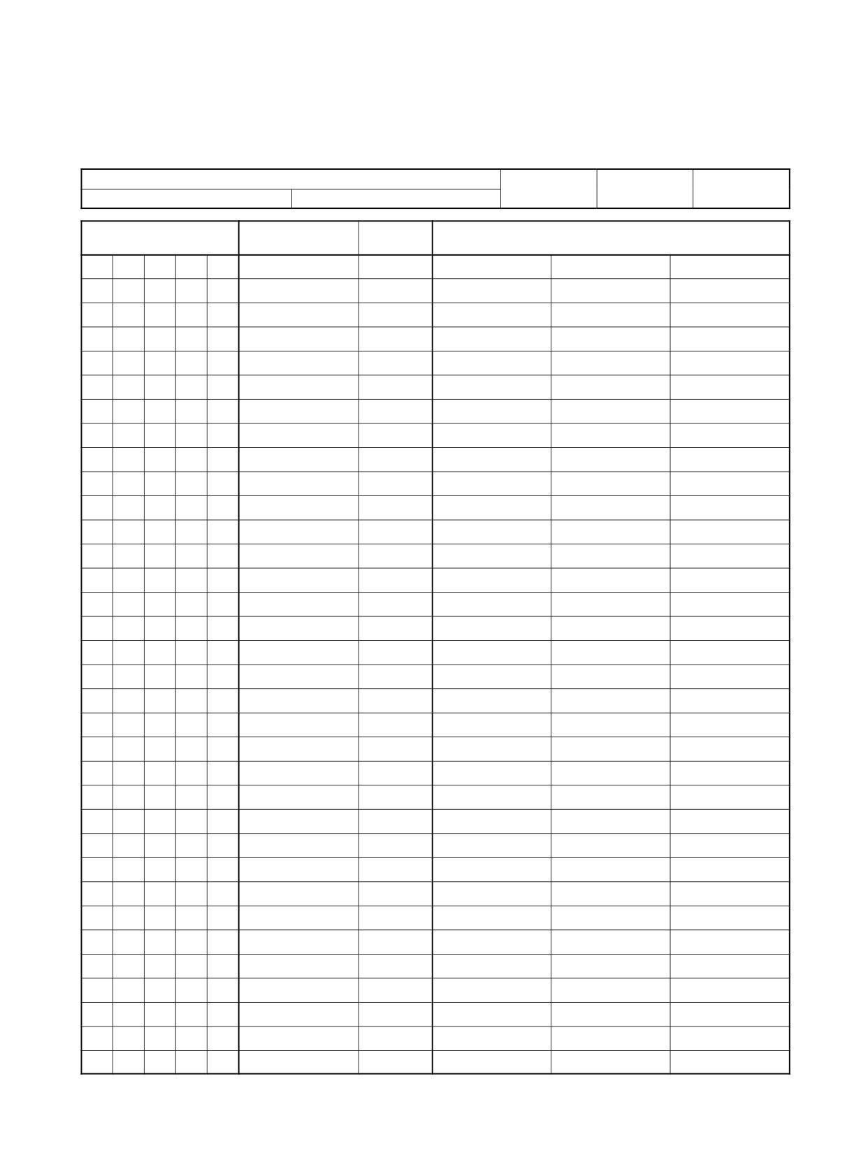
Appendix E
Program Coding Sheet
Name of system
Produced by
Verified by
Authorized by
PC
Chart No.
Address
Instruction
Function
Operands
code
0
0
0
1
0
2
0
3
0
4
0
5
0
6
0
7
0
8
0
9
1
0
1
1
1
2
1
3
1
4
1
5
1
6
1
7
1
8
1
9
2
0
2
1
2
2
2
3
2
4
2
5
2
6
2
7
2
8
2
9
3
0
3
1
3
2
3
3
585
Program Coding Sheet
Appendix E
Address
Instruction
Function
Operands
code
3
4
3
5
3
6
3
7
3
8
3
9
4
0
4
1
4
2
4
3
4
4
4
5
4
6
4
7
4
8
4
9
5
0
5
1
5
2
5
3
5
4
5
5
5
6
5
7
5
8
5
9
6
0
6
1
6
2
6
3
6
4
6
5
6
6
6
7
6
8
6
9
7
0
7
1
7
2
586
Program Coding Sheet
Appendix E
Address
Instruction
Function
Operands
code
7
3
7
4
7
5
7
6
7
7
7
8
7
9
8
0
8
1
8
2
8
3
8
4
8
5
8
6
8
7
8
8
8
9
9
0
9
1
9
2
9
3
9
4
9
5
9
6
9
7
9
8
9
9
587
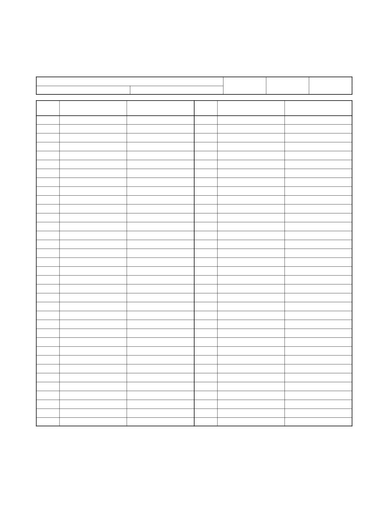
Appendix F
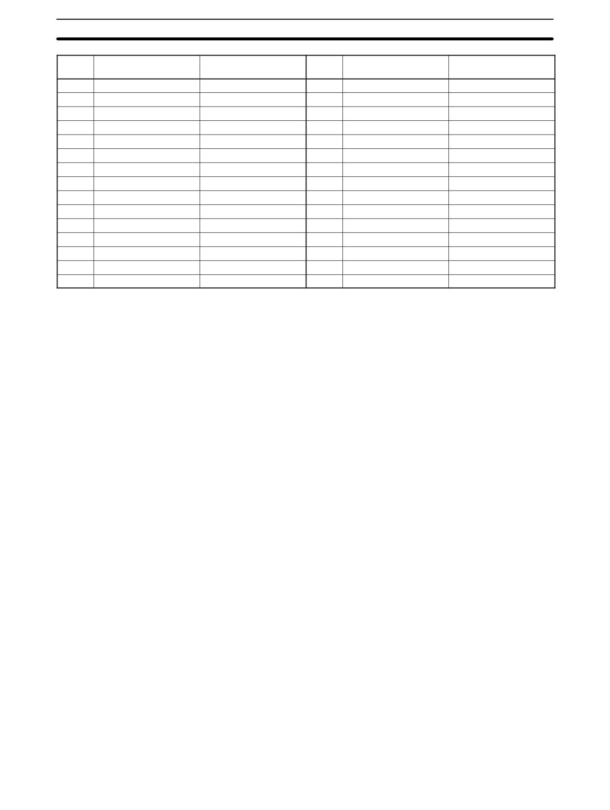
List of FAL Numbers
Name of system
Produced by
Verified by
Authorized by
PC model
Chart No.
FAL
FAL contents
Corrective measure
FAL
FAL contents
Corrective measure
No.
No.
00
35
01
36
02
37
03
38
04
39
05
40
06
41
07
42
08
43
09
44
10
45
11
46
12
47
13
48
14
49
15
50
16
51
17
52
18
53
19
54
20
55
21
56
22
57
23
58
24
59
25
60
26
61
27
62
28
63
29
64
30
65
31
66
32
67
33
68
34
69
589
List of FAL Numbers
Appendix F
FAL
FAL contents
Corrective measure
FAL
FAL contents
Corrective measure
No.
No.
70
85
71
86
72
87
73
88
74
89
75
90
76
91
77
92
78
93
79
94
80
95
81
96
82
96
83
97
84
99
590
Appendix G
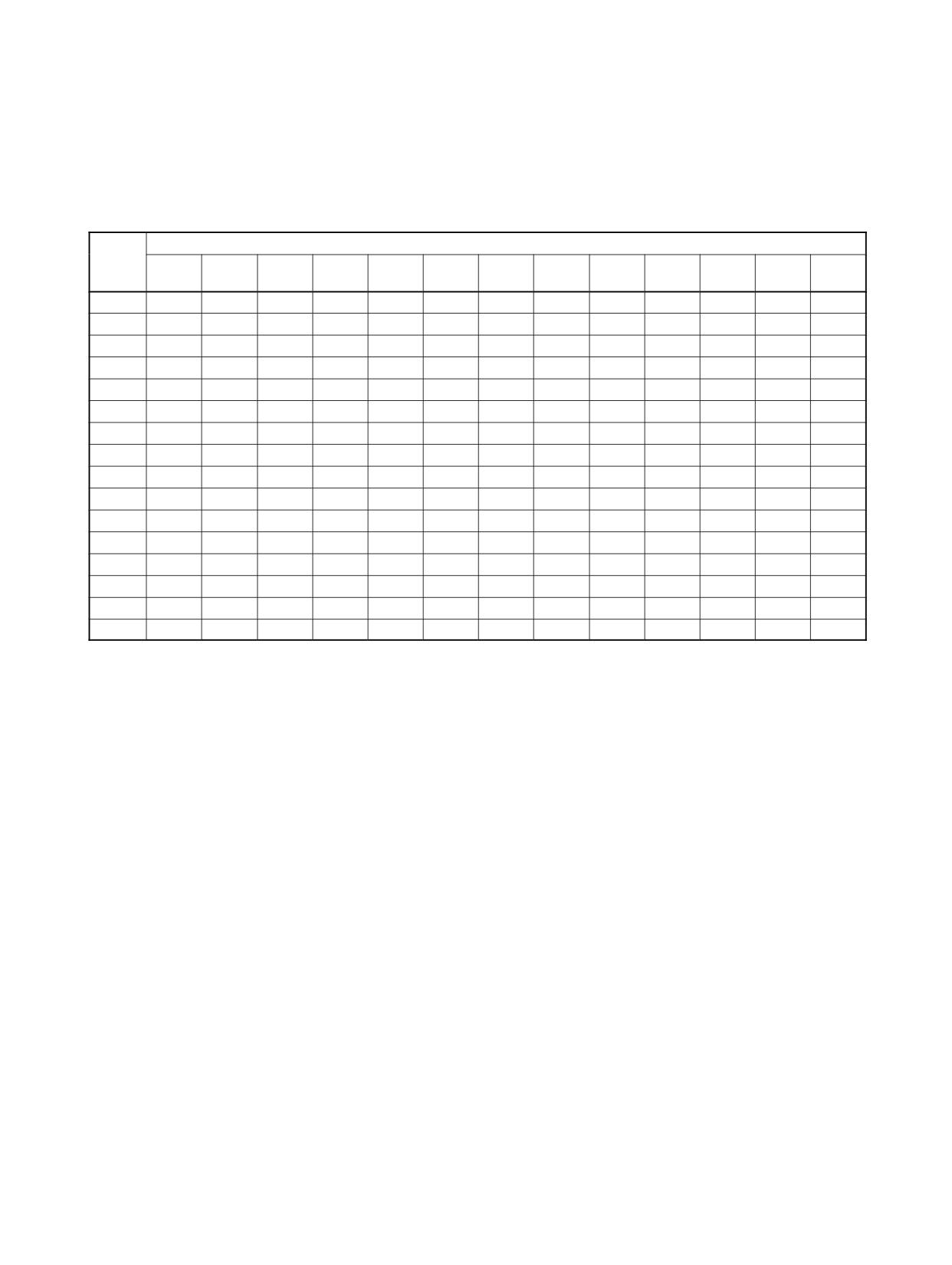
Extended ASCII
The following codes are used to output characters to the Programming Console or Data Access Console using
MSG(46). Refer to pages 493 for details.
Right
Left digit
dig it
0, 1,
2
3
4
5
6
7
A
B
C
D
E
F
8, 9
0
0
@
P
‘
p
-
@
P
‘
p
1
!
1
A
Q
a
q
!
1
A
Q
a
q
2
”
2
B
R
b
r
”
2
B
R
b
r
3
#
3
C
S
c
s
#
3
C
S
c
s
4
$
4
D
T
d
t
$
4
D
T
d
t
5
%
5
E
U
e
u
%
5
E
U
e
u
6
&
6
F
V
f
v
&
6
F
V
f
v
7
’
7
G
W
g
w
’
7
G
W
g
w
8
(
8
H
X
h
x
(
8
H
X
h
x
9
)
9
I
Y
i
y
)
9
I
Y
i
y
A
*
:
J
Z
j
z
*
:
J
Z
j
z
B
+
;
K
[
k
{
+
;
K
[
k
{
C
,
<
L
\
l
|
,
<
L
\
l
|
D
-
=
M
]
m
}
-
=
M
]
m
}
E
>
N
^
n
~
>
N
^
n
F
/
?
O
_
o
«
/
?
O
_
o
~
591
Index
CPM1/CPM1A, 225
Symbols
CPM2A/CPM2C, 259
SRM1, 275
**Empty**, 568
1:N NT Link, SRM1, 274
errors, 550
host link
CPM1/CPM1A, 223
Numbers
CPM2A/CPM2C, 227
SRM1, 264
1:1 PC Link
NT Link, CPM1/CPM1A, 224
CPM1/CPM1A, 225
types, 222
CPM2A/CPM2C, 259
wiring, 222
SRM1, 275
communications functions, 221
1:1 PC Link communications, I/O response timing
CPM1/CPM1A, 511
Communications Switch, setting
CPM2A/CPM2C, 521
CPM2A, 249, 258, 262
SRM1, 537
CPM2C, 250, 258, 263
CompoBus/S I/O Link Unit, 144, 210
using, 210
A-B
CompoBus/S I/O Master functions, 145
CompoBus/S I/O Slave functions, 144, 210
analog controls, 147
constants, operands, 361
analog I/O functions, 144, 162, 173
counter mode interrupts, CPM2A/CPM2C, 65
Analog I/O Units, 144
for CPM1A/CPM2A, 162
counters
for CPM2C, 173
conditions when reset, 390, 392
creating extended timers, 391
Analog Input Units
reversible counters, 391
averaging function, 179
input range, 176
cycle monitor time, PC Setup settings, 18
open-circuit detection function, 179
cycle time
analog inputs, 165, 180
CPM1/CPM1A
calculating, 509
Analog Output Units, output range, 178
effects on operations, 509
analog outputs, 166, 181
processes, 509
CPM2A/CPM2C
analog settings, 147
calculating, 519
arithmetic flags, 156, 361
effects on operations, 519
processes, 519
ASCII
SRM1
converting data, 445, 447
calculating, 534
table of codes, 591
effects on operations, 535
averaging function, 179
processes, 534
binary data, signed binary, 156
cycle time (minimum), PC Setup settings, 19
bits, controlling, 373
D
C
data
computation standards, 143
check levels, program checks, 547
decrementing, 479
incrementing, 479
checksum, calculating frame checksum, 496
decrementing. See data
clock, 160
definers, definition, 360
communications
1:1 NT Link
Differential Monitor, function, 156
CPM2A/CPM2C, 256
differential monitoring, 156
SRM1, 273
1:1 PC Link
differentiated instructions, 362
593
Index
function codes, 360
H
display, for Temperature Sensor Units, 204
high-speed counter interrupts
duty ratio
CPM1/CPM1A, 83
fixed duty ratio pulse outputs, 98
CPM2A/CPM2C, 43
variable duty ratio pulse outputs, 108
high-speed counters, CPM2A/CPM2C, 42
hold bit status, PC Setup settings, 17
host link
E
CPM1/CPM1A, 223
CPM2A/CPM2C, 227
error codes, programming, 381
SRM1, 264
error log, PC Setup settings, 21
host link commands
**, 300
error log area, 548
EX, 300
FK, 294
error messages, programming, 493
IC, 301
errors
KC, 295
communications, 550
KR, 293
degree of error in pulse outputs, 143
KS, 292
fatal, 550
MF, 291
general, 546
MM, 296
MS, 289
non-fatal, 549
QQ, 298
other, 550
R#, 285
PC Setup, 2
R$, 286
programming, 547
RC, 278
Programming Console operations, 546
RD, 279
programming messages, 493
RG, 279
resetting, 381
RH, 278
types, 546
RJ, 280
user-defined errors, 548
RL, 278
execution condition, definition, 332
RP, 297
RR, 277
expansion instructions, 367, 368, 558
SC, 290
function codes, 157
TS, 296
W#, 287
Expansion Units, using, 161
W$, 288
WC, 282
WD, 284
WG, 283
F
WH, 282
WJ, 284
FAL area, 381
WL, 281
WP, 297
FAL numbers, table, 589
WR, 281
XZ, 300
FAL(06), 548
FALS(07), 548
flag
I-J
arithmetic, programming example, 429, 433
CY
I/O points, refreshing, 494
clearing, 453
I/O response time
setting, 453
1:1 PC Link communications
CPM1/CPM1A, 511
flags, error and arithmetic, 561
CPM2A/CPM2C, 521
Frame Check Sequence. See frames, FCS
SRM1, 537
CPM1/CPM1A. See timing
frame checksum, calculating with FCS(--), 496
CPM2A/CPM2C. See timing
frames, FCS, 235
SRM1. See timing
incrementing, 479
function codes, 360
expansion instructions, 157, 158, 159, 367, 368
indicators, CompoBus/S LED indicators, 211, 216
594
Index
indirect addressing, 361
HTS(65), 449
IL(02), 347, 377-379
INI(61), 130
ILC(03), 347, 377-379
initialization processes, CPM1/CPM1A, 508
INC(38), 479
INI(61), 130, 395
input interrupts
INT(89), 80, 497
CPM1/CPM1A, 75
IORF(97), 494
CPM2A/CPM2C, 27
JME(05), 379
input interrupts (counter mode), CPM2A/CPM2C, 65
JMP(04), 379
JMP(04) and JME(05), 349
input mode
KEEP(11), 375
CPM2A/CPM2C, 46
in controlling bit status, 351
selecting, 134
ladder instructions, 333
input time constants, PC Setup settings, 19
LD, 334, 372
LD NOT, 334, 372
inputs, quick-response inputs, 149
MAX(--), 468
instruction set, 555
MCRO(99), 154, 482
ACC(--), 487
MIN(--), 470
ADB(50), 463
MLB(52), 466
ADD(30), 453
MLPX(76), 438
ADDL(54), 458
MOV(21), 407
AND, 334, 372
MOVB(82), 415
combining with OR, 335
MOVD(83), 416
AND LD, 337, 373
MSG(46), 493
combining with OR LD, 340
MUL(32), 456
use in logic blocks, 339
MULL(56), 462
AND NOT, 334, 372
MVN(22), 408
ANDW(34), 476
NEG(--), 451
ASC(86), 445
NOP(00), 377
ASFT(17), 406
NOT, 331
ASL(25), 401
operands, 330
ASR(26), 402
OR, 335, 372
AVG(--), 472
combining with AND, 335
BCD(24), 436
OR LD, 338, 373
BCDL(59), 437
combining with AND LD, 340
BCMP(68), 430
use in logic blocks, 339
BCNT(67), 495
OR NOT, 335, 372
BIN(23), 435
ORW(35), 477
BINL(58), 436
OUT, 336, 373
BSET(71), 410
OUT NOT, 336, 373
CLC(41), 453
PID(--), 422
CMP(20), 428
PRV(62), 397
CMPL(60), 432
PULS(65), 129, 483
CNT, 390
PWM(--), 490
CNTR(12), 391
RESET, 350
COLL(81), 413
RET(93), 482
COM(29), 475
ROL(27), 402
CTBL(63), 392
ROR(28), 403
DEC(39), 479
RSET, 374-375
DIFD(14), 351, 376-385
RXD(47), 248, 272, 501
using in interlocks, 378
SBB(51), 464
using in jumps, 380
SBN(92), 26, 74, 482
DIFU(13), 351, 376-385
SBS(91), 480
using in interlocks, 378
SCL(66), 417
using in jumps, 380
SCL2(--), 418
DIST(80), 411
SCL3(--), 420
DIV(33), 457
SDEC(78), 442
DIVL(57), 462
SET, 350, 374-375
DMPX(77), 440
SFT(10), 400
DVB(53), 466
SFTR(84), 405
END(01), 337, 377
SLD(74), 404
FAL(06), 381
SNXT(09), 381
FALS(07), 381
SPED(64), 129, 485
FCS(--), 496
SRCH(--), 467
HEX(--), 447
SRD(75), 404
595
Index
STC(40), 453
interval timers, 81
STEP(08), 381
scheduled interrupt mode, 81
STH(--), 450
masking, 80
STIM(69), 500
setting modes, 77
STUP(--), 505
types, 74
SUB(31), 454
unmasking, 81
SUBL(55), 460
CPM2A/CPM2C
SUM(--), 474
high-speed counter, 43
SYNC(--), 492
input interrupts, 27
TCMP(85), 429
interval timers, 34
terminology, 330
scheduled interrupt mode, 36
TIM, 385
masking, 31
TIMH(15), 386
order of priority, 27
using in jumps, 380
selecting interrupts to be used, 48
TIML(--), 388
setting modes, 30
TMHH(--), 387
types, 26
using in jumps, 380
unmasking, 31, 32
TXD(48), 248, 272, 503
high-speed counter, programming, 54, 87
WSFT(16), 401
masking, masking, 32
XCHG(73), 411
SRM1
XFER(70), 409
interval timers, 91
XNRW(37), 478
scheduled interrupt mode, 92
XORW(36), 477
types, 91
ZCP(--), 433
unmasking, 500
ZCPL(--), 434
interval timer interrupts
instructions
CPM1/CPM1A, 81
CPM2A/CPM2C, 34
execution times
SRM1, 91
CPM1/CPM1A, 514
CPM2A/CPM2C, 524
JOG operation, CPM2A/CPM2C, 106
SRM1, 539
jogging, 125
expansion, 157
instruction set lists, 366
jump numbers, 379
mnemonics list, ladder, 369
jumps, 379-380
right-hand instructions, coding multiple, 345
subroutines, 480
INT(89), 80
L
interlocks, 377-379
ladder diagram
using self-maintaining bits, 352
branching, 345
interrupt functions
IL(02) and ILC(03), 347
CPM1/CPM1A, 73
using TR bits, 346
CPM2A/CPM2C, 26
combining logic blocks, 341
SRM1(-V2), 91
controlling bit status
using DIFU(13) and DIFD(14), 351, 376-385
interrupt processing
using KEEP(11), 375-376
calculating response time
using OUT and OUT NOT, 336
CPM1/CPM1A, 513
using SET and RESET, 350
CPM2A/CPM2C, 523
using SET and RSET, 374-375
masking
converting to mnemonic code, 332-350
CPM1/CPM1A, 513
display via GPC, FIT, LSS, or SSS, 331
CPM2A/CPM2C, 523
instructions
SRM1, 538
combining, AND LD and OR LD, 340
timing
controlling bit status
CPM1/CPM1A, 513
using KEEP(11), 351
CPM2A/CPM2C, 523
using OUT and OUT NOT, 373
SRM1, 538
format, 360
interrupts
notation, 360
control, 497
structure, 331
CPM1/CPM1A
using logic blocks, 337
counter mode, 79
ladder diagram instructions, 372-373
high-speed counter, 83
logic block instructions, converting to mnemonic code,
overflows and underflows, 85
337-344
input interrupt mode, 77
input interrupts, 75
logic blocks. See ladder diagram
596
Index
M
P
macro function, subroutines. See programming
PC Link, CPM2A/CPM2C, 259
masking
PC Setup. See settings
CPM1/CPM1A interrupt processes, 513
PC Setup settings
CPM2A/CPM2C interrupt processes, 523
CPM1/CPM1A, 3
SRM1 interrupt processes, 538
CPM2A/CPM2C, 7
MCRO(99), 154
SRM1(-V2), 13
memory areas
peripheral port, servicing time, 18
AR area bits
peripheral port servicing time, PC Setup settings, 18
CPM2A/CPM2C, 574
SRM1, 580
positioning, 123
flags and control bits
precautions, general, xiii
CPM1/CPM1A, 565
program coding sheet, 585
CPM2A/CPM2C, 571
SRM1, 578
Program Memory, structure, 332
structure
program write protection, PC Setup settings, 17
CPM1/CPM1A, 304, 565
CPM2A/CPM2C, 305, 570
programming
SRM1, 306, 577
errors, 547
for temperature monitoring, 198
messages, programming, 493
high-speed counter
mnemonic code, converting, 332-350
CPM1/CPM1A, 87
CPM2A/CPM2C, 54
MSG(46), 548
instructions, 555
interrupts, 54, 87
jumps, 349
N
macro function, subroutines, 154
precautions, 354
nesting, subroutines, 481
preparing data in data areas, 410
no-protocol communications
program coding sheet, 585
CPM2A/CPM2C, 247
special features, 157
program example, 253, 273
writing, 330
SRM1, 268
programs
transmission data configuration, 248, 272
checking, check levels, 547
transmission flags, 248, 272
executing, 356
normally open/closed condition, definition, 331
PULS(65), 129
NOT, definition, 331
pulse output
NT Link
errors/delays, 143
CPM1/CPM1A, 224
fixed duty ratio, 98
CPM2A/CPM2C, 256
synchronized to input frequency, 131, 492
SRM1, 273, 274
variable duty ratio, 108
pulse output functions
CPM1A, 128
O
CPM2A/CPM2C, 94
open-circuit detection function, 179
PV
CNTR(12), 391
operand bit, 332
timers and counters, 385
operands, 360
allowable designations, 360
requirements, 360
R
operations
CPM1/CPM1A internal processing, flowchart, 508
range code, 169, 187
effects on CPM1/CPM1A cycle time, 509
range comparison interrupts, CPM2A/CPM2C, 49
effects on CPM2A/CPM2C cycle time, 519
effects on SRM1 cycle time, 535
right-hand instructions, coding. See instructions
SRM1 internal processing, flowchart, 533
RS-232C
output bit
communications
controlling ON/OFF time, 374
receiving
controlling status, 350, 352
CPM2A/CPM2C, 255
597
Index
SRM1, 268
T-W
transmitting
CPM2A/CPM2C, 254
target value comparison table, CPM2A/CPM2C, 54
SRM1, 268
control bits, SRM1, 269
TC numbers, 384
RS-232C port, servicing time (CPM2A/CPM2C/SRM1), 18
temperature sensor input functions, 144
RS-232C port servicing time, PC Setup settings, 18
Temperature Sensor Units, 144, 189
RXD(47), 248, 272
time
reading the time, 160
setting the time, 160
S
timers, conditions when reset, 385, 386
TIML(--), 389
SBN(92), 26, 74
TMHH(--), 388
serial communications, CPM2A/CPM2C, 247
timing
settings
basic instructions
basic operations
CPM1/CPM1A, 514
hold bit status, 17
CPM2A/CPM2C, 524
startup mode, 16
SRM1, 539
changing, 2
CPM1/CPM1A cycle time, 509
communications, 222
CPM2A/CPM2C cycle time, 519
host link
I/O response time
CPM1/CPM1A, 223
CPM1/CPM1A, 510
CPM2A/CPM2C, 227
CPM2A/CPM2C, 520
SRM1, 264
SRM1, 536
defaults, 2
instruction execution
I/O operations, 16
CPM1/CPM1A. See instruction
port servicing scan time, 18, 19
CPM2A/CPM2C. See instruction
SRM1. See instruction
seven-segment displays, converting data, 442
interrupt processing
signed binary data, 155, 156
CPM1/CPM1A, 513
CPM2A/CPM2C, 523
SPED(64), 129
SRM1, 538
startup mode, PC Setup settings, 16
special instructions
subroutine number, 482
CPM1/CPM1A, 514
CPM2A/CPM2C, 524, 531
subroutines, interrupt subroutines, 26
SRM1, 539, 543
SV
SRM1 cycle time, 534
CNTR(12), 391
TR bits, use in branching, 346
timers and counters, 385
two-decimal place display, 204
synchronized pulse control, 131
errors/delays, 143
TXD(48), 248, 272
synchronized pulse output, 492
write protecting the program, PC Setup settings, 17
598
Revision History
A manual revision code appears as a suffix to the catalog number on the front cover of the manual.
Cat. No. W353-E1-3
Revision code
The following table outlines the changes made to the manual during each revision. Page numbers refer to the
previous version.
Revision
Date
Revised content
code
1
May 1999
Original production
2
January 2000
Information on new Expansion Units and the relevant PCs was added throughout the manual. Additional changes were made
on the following pages:
Page xi: Updated to new contents of manual.
Page xv: Change made to first caution.
Page xvi: Change made to first installation precaution.
Page xvii: Ground precaution changed to warning and moved to safety precaution section. Other precautions expanded
or reworded.
Page xv: Caution on online editing reworded.
Page xvi: First installation precaution expanded.
Pages 9, 11, 185, 186, 194, 195, 200: Host Link unit number added to port settings.
Pages 11, 186, 195: Communications mode description changed.
Page 17: Setting to protect memory changed.
Page 24: Position of notes changed.
Pages 54, 55, 56, 57, 58, 71, 79, 92, 99, 106, 107, 112, 113, 115, 116, 117, 119, 133, 153, 154, 160, 174, 175, 198, 201,
213, 348, 414, 425, 428, 429: Changes to graphics.
Pages 96, 111: Change to “Pulse Output Flag” description.
Page 120: Pulse output number changed in program.
Page 134: Section added on data calculations.
Pages 137 to 139: Analog control sections combined.
Pages 148, 149: Corrections made for function codes.
Page 159: Table removed.
Pages 187, 207: Change to first line of program.
Pages 190, 300, 475: Note added.
Pages 238, 367, 444: Changes made to tables.
Pages 283-285: Updated to new contents and order of section.
Pages 293, 294: Changes made to existing table. Table added.
Pages 311-314: Information added to “Precautions.”
Page 313: Changes made to graphics and “Limitations.” Section moved to the end of section on “TMHH.”
Page 314: Changes made to graphics and “Limitations.”
Pages 387, 388: Example added.
Page 413: Section on“SRCH” moved before section on “MAX.”
Page 443: Information on “I/O refreshing” added.
Page 490: “Volume” removed from information on SR 250 and SR 251.
Pages 490, 491, 495-497, 501-503: “Read/write” column added to table.
Page 497: Changes made to information on AR 02.
Page 498: Changes made to information on AR 1111.
Page 499: Changes made to information on AR 1314.
599
Revision History
Revision
Date
Revised content
code
3
February 2001
Revisions and additions were made accompanying specifications changes and new products.
The CPM1A-MAD11 Analog I/O Unit was added as section 3-1-2 and the CPM1A-DRT21 DeviceNet I/O Link Unit was
added as section 3-4.
Interrupt programming precautions were added to sections 2-1 and 2-3.
Specific changes are as follows:
Pages xi, 1, 23, 148, 163, 177, 197, 203, 331, 341, 383, 495, 500, and 546: CPM2C-S added.
Pages 7 and 21: Information added on DIP switch changes.
Page 138: Note added.
Page 161: Information added on startup operation.
Page 162: Programming example modified.
Pages 295 to 298 and 300: Models added.
Page 545: Description of AR 1314 altered.
Page 550: Description of AR 0712 added.
600