SYSMAC CPM1/CPM1A/CPM2A/CPM2C/SRM1(–V2). Programmable Controllers (2001) - page 7
Conversion Instructions
Section
7-20
Flags
ER:
The content of S is not BCD.
Indirectly addressed DM word is non-existent. (Content of *DM word is
not BCD, or the DM area boundary has been exceeded.)
EQ:
ON when the result is zero.
7-20-2
BINARY-TO-BCD - BCD(24)
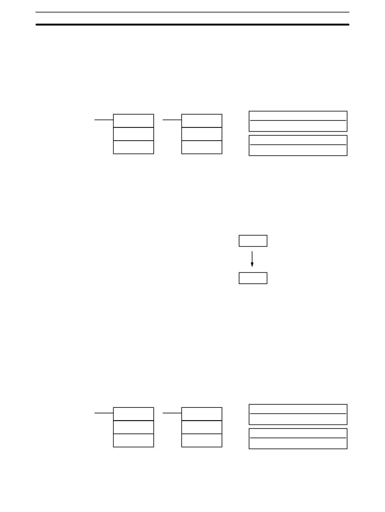
Ladder Symbols
Operand Data Areas
S: Source word (binary)
BCD(24)
@BCD(24)
IR, SR, AR, DM, HR, LR
S
S
R: Result word
R
R
IR, SR, AR, DM, HR, LR
Limitations
If the content of S exceeds 270F, the converted result would exceed 9999 and
BCD(24) will not be executed. When the instruction is not executed, the content
of R remains unchanged.
DM 6144 to DM 6655 cannot be used for R.
Description
BCD(24) converts the binary (hexadecimal) content of S into the numerically
equivalent BCD bits, and outputs the BCD bits to R. Only the content of R is
changed; the content of S is left unchanged.
Binary
S
BCD
R
BCD(24) can be used to convert binary to BCD so that displays on the Program-
ming Console or any other programming device will appear in decimal rather
than hexadecimal. It can also be used to convert to BCD to perform BCD arith-
metic operations rather than binary arithmetic operations, e.g., when BCD and
binary values must be added.
Flags
ER:
Indirectly addressed DM word is non-existent. (Content of *DM word is
not BCD, or the DM area boundary has been exceeded.)
EQ:
ON when the result is zero.
7-20-3
DOUBLE BCD-TO-DOUBLE BINARY - BINL(58)
Ladder Symbols
Operand Data Areas
S: First source word (BCD)
BINL(58)
@BINL(58)
IR, SR, AR, DM, HR, TC, LR
S
S
R: First result word
R
R
IR, SR, AR, DM, HR, LR
Limitations
This instruction is available in the CPM2A/CPM2C only.
DM 6144 to DM 6655 cannot be used for R.
436
Conversion Instructions
Section
7-20
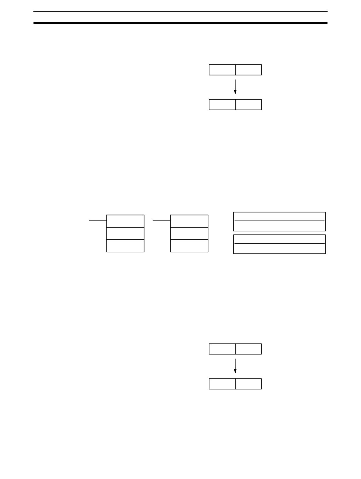
When the execution condition is OFF, BINL(58) is not executed. When the
Description
execution condition is ON, BINL(58) converts an eight-digit number in S and S+1
into 32-bit binary data, and outputs the converted data to R and R+1.
S + 1
S
BCD
Binary
R + 1
R
Flags
ER:
The contents of S and/or S+1 words are not BCD.
Indirectly addressed DM word is non-existent. (Content of *DM word is
not BCD, or the DM area boundary has been exceeded.)
EQ:
ON when the result is zero.
7-20-4
DOUBLE BINARY-TO-DOUBLE BCD - BCDL(59)
Ladder Symbols
Operand Data Areas
S: First source word (binary)
BCDL(59)
@BCDL(59)
IR, SR, AR, DM, HR, LR
S
S
R: First result word
R
R
IR, SR, AR, DM, HR, LR
Limitations
This instruction is available in the CPM2A/CPM2C only.
If the content of S exceeds 05F5E0FF, the converted result would exceed
99999999 and BCDL(59) will not be executed. When the instruction is not
executed, the content of R and R+1 remain unchanged.
DM 6144 to DM 6655 cannot be used for R.
Description
BCDL(59) converts the 32-bit binary content of S and S+1 into eight digits of
BCD data, and outputs the converted data to R and R+1.
Binary
S + 1
S
BCD
R + 1
R
Flags
ER:
Content of R and R+1 exceeds 99999999.
Indirectly addressed DM word is non-existent. (Content of *DM word is
not BCD, or the DM area boundary has been exceeded.)
EQ:
ON when the result is zero.
437
Conversion Instructions
Section
7-20
7-20-5
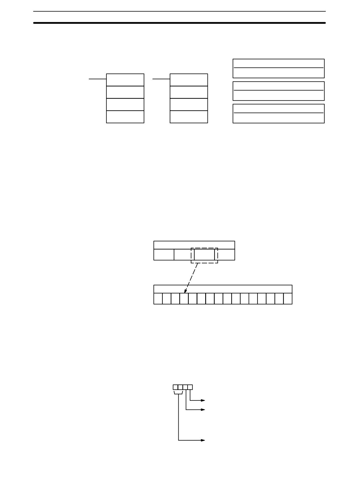
4-TO-16 DECODER - MLPX(76)
Operand Data Areas
Ladder Symbols
S: Source word
IR, SR, AR, DM, HR, TC, LR
MLPX(76)
@MLPX(76)
Di: Digit designator
S
S
IR, SR, AR, DM, HR, TC, LR, #
Di
Di
R: First result word
R
R
IR, SR, AR, DM, HR, LR
Limitations
The rightmost two digits of Di must each be between 0 and 3.
All result words must be in the same data area.
DM 6144 to DM 6655 cannot be used for R.
Description
When the execution condition is OFF, MLPX(76) is not executed. When the
execution condition is ON, MLPX(76) converts up to four, four-bit hexadecimal
digits from S into decimal values from 0 to 15, each of which is used to indicate a
bit position. The bit whose number corresponds to each converted value is then
turned ON in a result word. If more than one digit is specified, then one bit will be
turned ON in each of consecutive words beginning with R. (See examples, be-
low.)
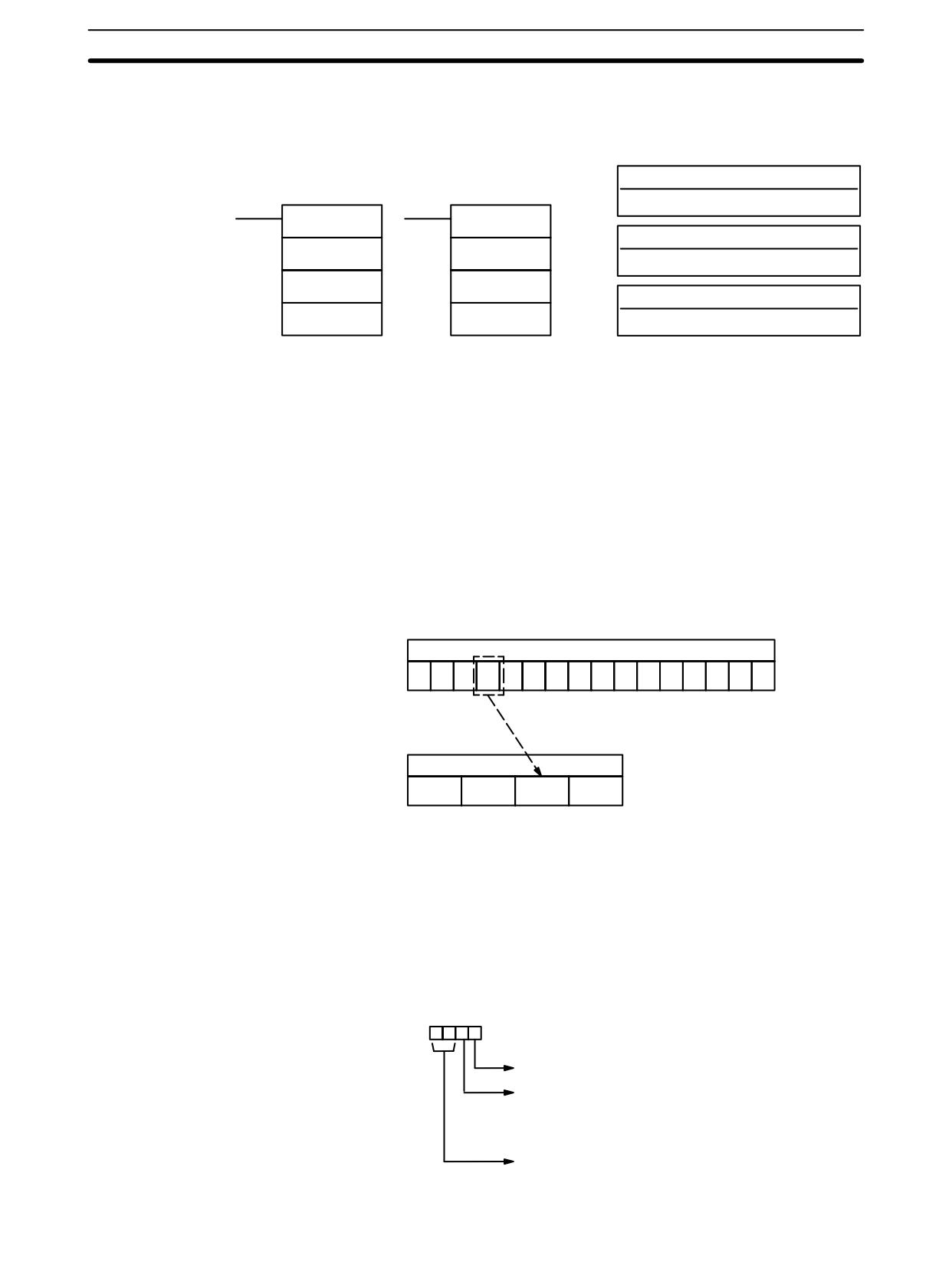
The following is an example of a one-digit decode operation from digit number 1
of S, i.e., here Di would be 0001.
Source word
C
Bit C (i.e., bit number 12) turned ON.
First result word
0
0
0
1
0
0
0
0
0
0
0
0
0
0
0
0
The first digit and the number of digits to be converted are designated in Di. If
more digits are designated than remain in S (counting from the designated first
digit), the remaining digits will be taken starting back at the beginning of S. The
final word required to store the converted result (R plus the number of digits to be
converted) must be in the same data area as R, e.g., if two digits are converted,
the last word address in a data area cannot be designated; if three digits are con-
verted, the last two words in a data area cannot be designated.
Digit Designator
The digits of Di are set as shown below.
Digit number:
3210
Specifies the first digit to be converted (0 to 3)
Number of digits to be converted (0 to 3)
0: 1 digit
1: 2 digits
2: 3 digits
3: 4 digits
Not used (Set to zero)
438
Conversion Instructions
Section
7-20
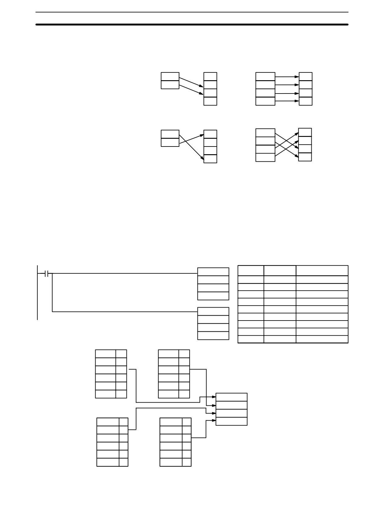
Some example Di values and the digit-to-word conversions that they produce
are shown below.
Di: 0010
Di: 0030
S
S
0
R
0
R
1
R + 1
1
R + 1
2
2
R + 2
3
3
R + 3
Di: 0031
Di: 0023
S
S
R
R
0
0
R + 1
R + 1
1
1
2
R + 2
2
R + 2
3
R + 3
3
Flags
ER:
Undefined digit designator, or R plus number of digits exceeds a data
area.
Indirectly addressed DM word is non-existent. (Content of *DM word is
not BCD or the DM area boundary has been exceeded.)
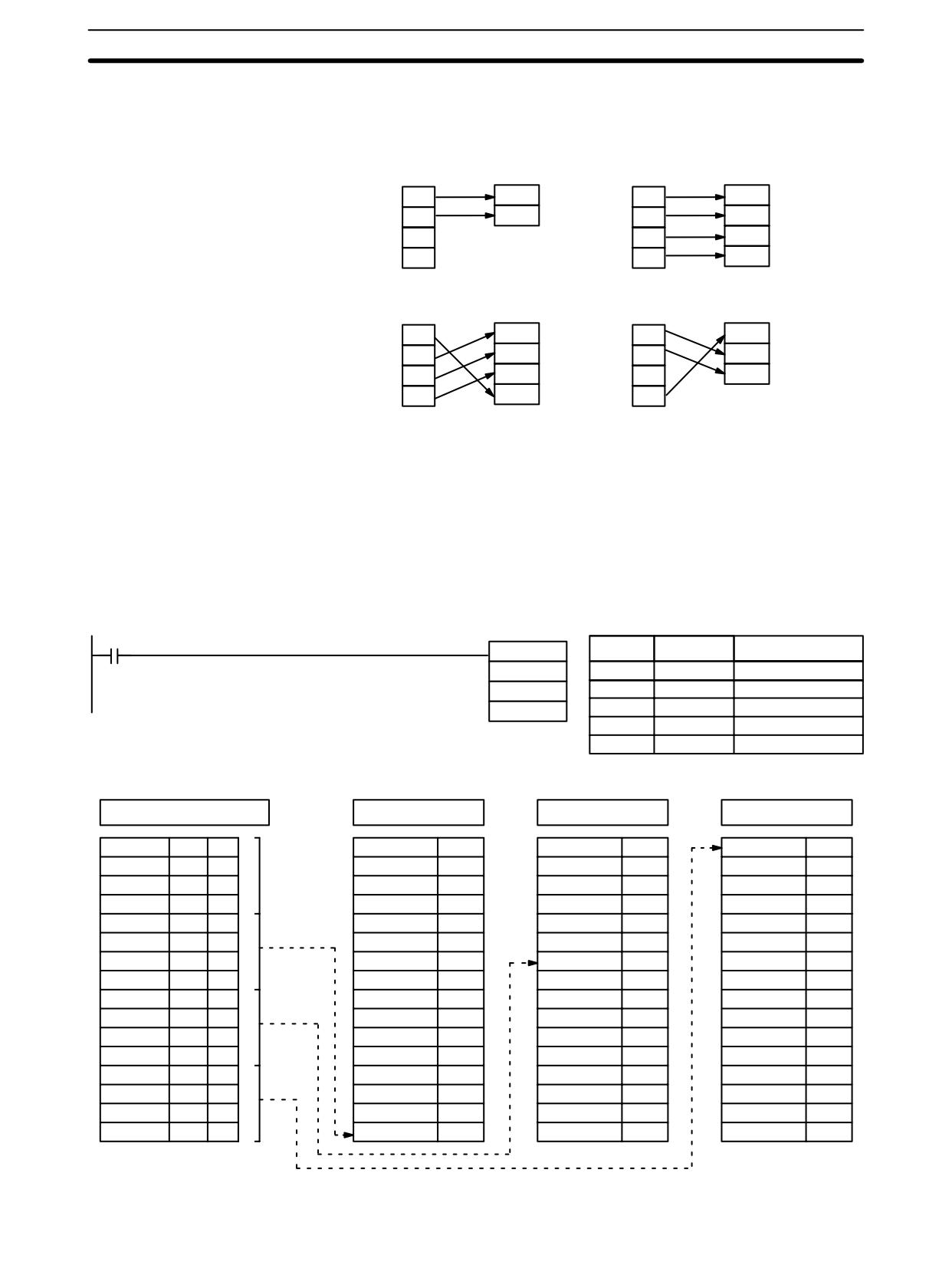
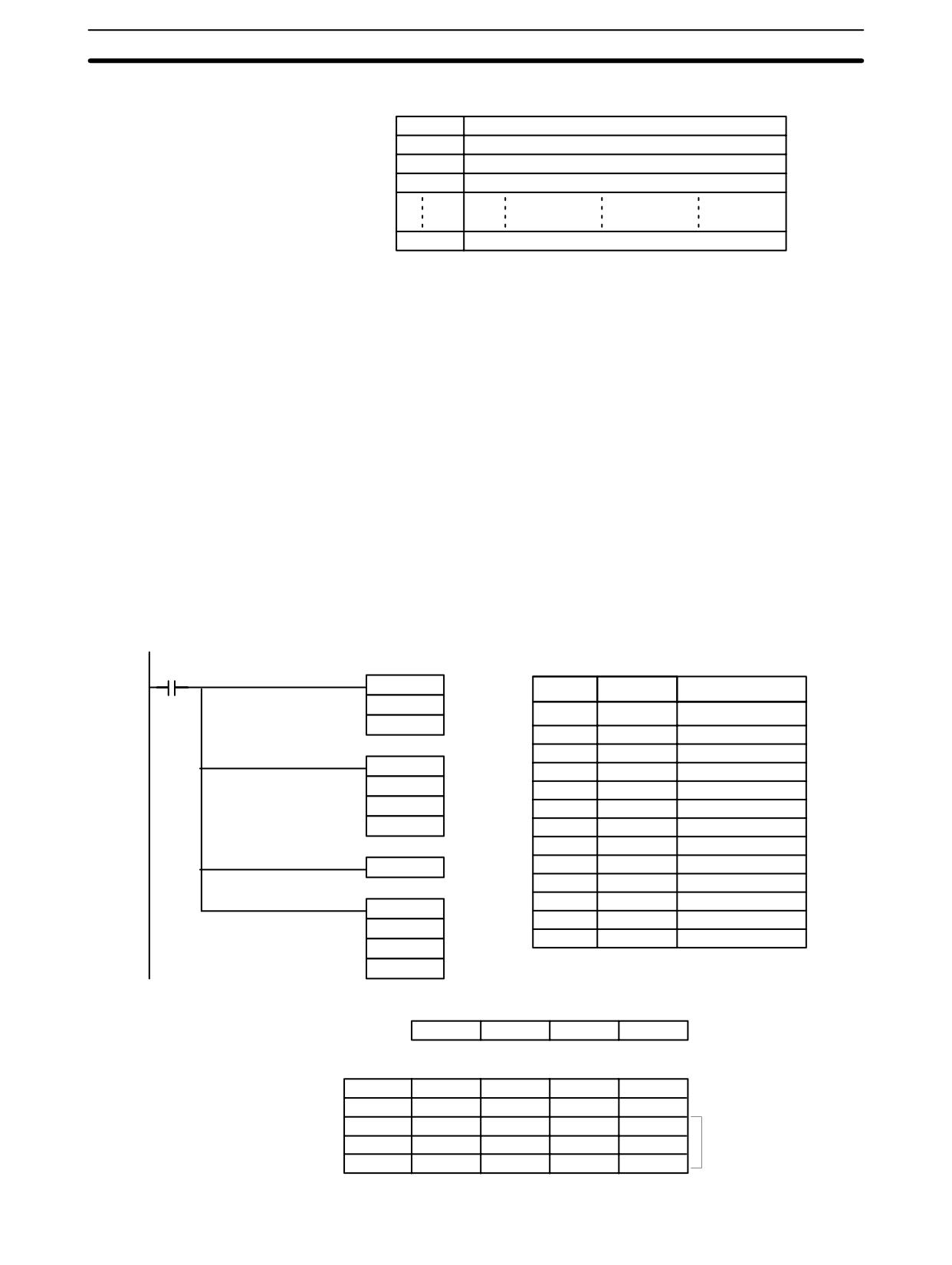
The following program converts digits 1 to 3 of data from DM 0020 to bit positions
Example
and turns ON the corresponding bits in three consecutive words starting with HR
10. Digit 0 is not converted.
00000
MLPX(76)
Address
Instruction
Operands
DM 0020
00000
LD
00000
#0021
00001
MLPX(76)
HR 10
DM
0020
#
0021
HR
10
S: DM 0020
R: HR 10
R+1: HR 11
R+2: HR 12
DM 0020
00
HR 1000
0
HR 1100
0
HR 1200
1
DM 0020
01
Not
HR 1001
0
HR 1101
0
HR 1201
0
DM 0020
02
Converted
HR 1002
0
HR 1102
0
HR 1202
0
DM 0020
03
HR 1003
0
HR 1103
0
HR 1203
0
DM 0020
04
1
HR 1004
0
HR 1104
0
HR 1204
0
15
DM 0020
05
1
HR 1005
0
HR 1105
0
HR 1205
0
DM 0020
06
1
HR 1006
0
HR 1106
1
HR 1206
0
DM 0020
07
1
HR 1007
0
HR 1107
0
HR 1207
0
DM 0020
08
0
HR 1008
0
HR 1108
0
HR 1208
0
6
DM 0020
09
1
HR 1009
0
HR 1109
0
HR 1209
0
DM 0020
10
1
HR 1010
0
HR 1110
0
HR 1210
0
DM 0020
11
0
HR 1011
0
HR 1111
0
HR 1211
0
DM 0020
12
0
HR 1012
0
HR 1112
0
HR 1212
0
0
DM 0020
13
0
HR 1013
0
HR 1113
0
HR 1213
0
DM 0020
14
0
HR 1014
0
HR 1114
0
HR 1214
0
DM 0020
15
0
HR 1015
1
HR 1115
0
HR 1215
0
439
Conversion Instructions
Section
7-20
7-20-6
16-TO-4 ENCODER - DMPX(77)
Operand Data Areas
Ladder Symbols
SB: First source word
IR, SR, AR, DM, HR, TC, LR
DMPX(77)
@DMPX(77)
R: Result word
SB
SB
IR, SR, AR, DM, HR, LR
R
R
Di: Digit designator
Di
Di
IR, SR, AR, DM, HR, TC, LR, #
Limitations
The rightmost two digits of Di must each be between 0 and 3.
All source words must be in the same data area.
DM 6144 to DM 6655 cannot be used for SB, R, or Di.
When the execution condition is OFF, DMPX(77) is not executed. When the
Description
execution condition is ON, DMPX(77) determines the position of the highest ON
bit in S, encodes it into single-digit hexadecimal value corresponding to the bit
number of the highest ON bit number, then transfers the hexadecimal value to
the specified digit in R. The digits to receive the results are specified in Di, which
also specifies the number of digits to be encoded.
The following is an example of a one-digit encode operation to digit number 1 of
R, i.e., here Di would be 0001.
First source word
0
0
0
1
0
0
0
1
0
0
0
1
0
1
1
0
C transferred to indicate bit number 12 as
the highest ON bit.
Result word
C
Up to four digits from four consecutive source words starting with S may be en-
coded and the digits written to R in order from the designated first digit. If more
digits are designated than remain in R (counting from the designated first digit),
the remaining digits will be placed at digits starting back at the beginning of R.
The final word to be converted (S plus the number of digits to be converted) must
be in the same data area as SB.
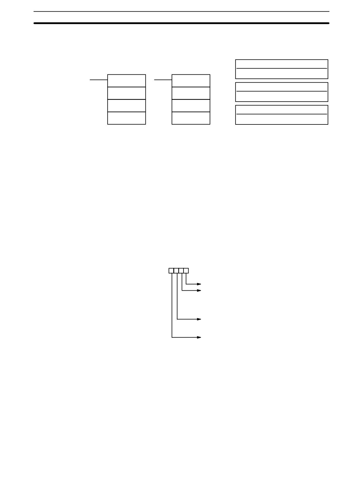
Digit Designator
The digits of Di are set as shown below.
Digit numbers: 3 2 1 0
Specifies the first digit to receive converted data (0 to 3).
Number of words to be converted (0 to 3)
0: 1 word
1: 2 words
2: 3 words
3: 4 words
Not used.
440
Conversion Instructions
Section
7-20
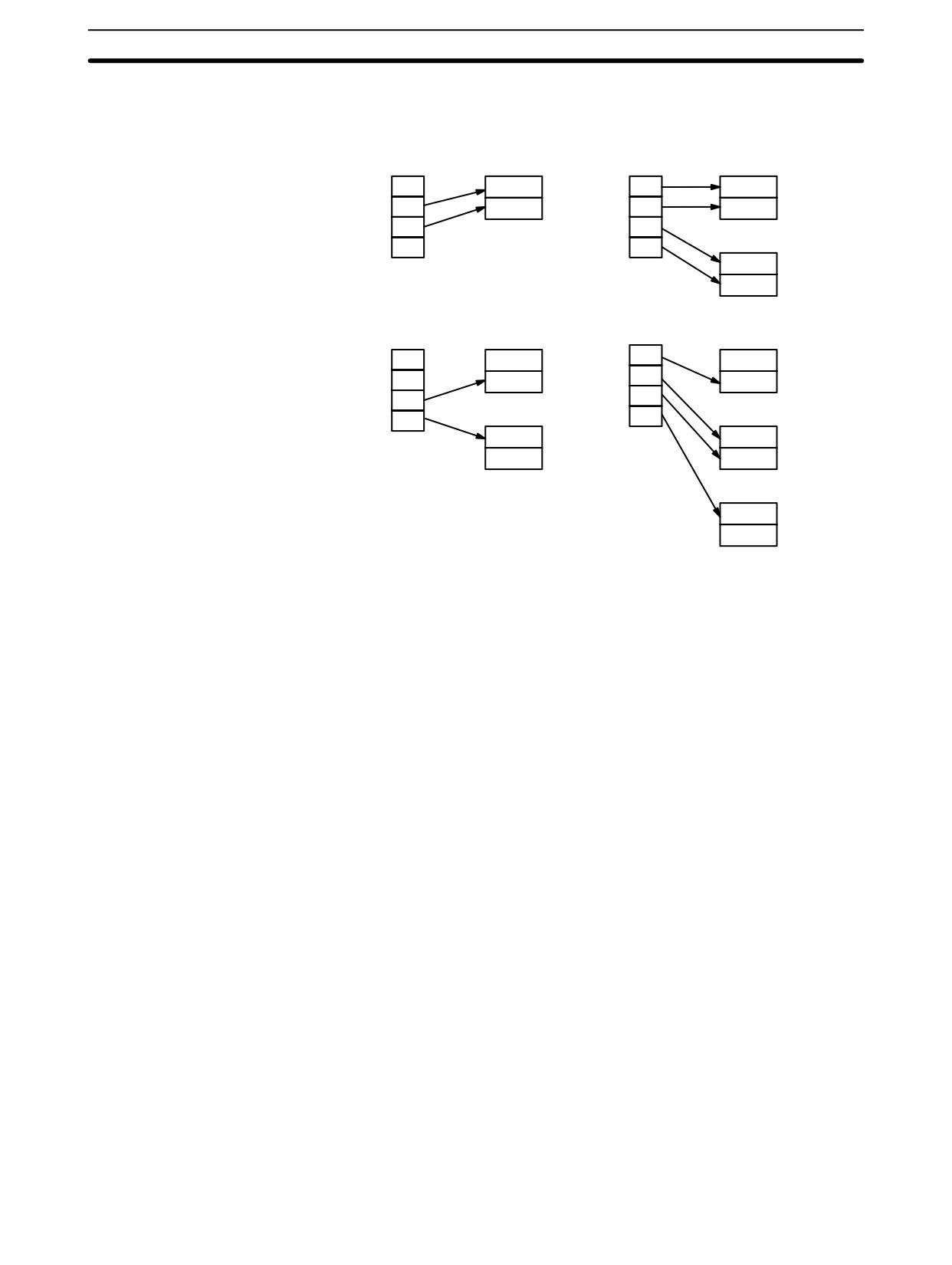
Some example Di values and the word-to-digit conversions that they produce
are shown below.
Di: 0011
Di: 0030
R
R
S
0
S
0
S + 1
1
S + 1
1
2
S + 2
2
3
S + 3
3
Di: 0013
Di: 0032
R
R
S
0
S
0
S + 1
1
S + 1
1
S + 2
2
2
3
S + 3
3
Flags
ER:
Undefined digit designator, or S plus number of digits exceeds a data
area.
Content of a source word is zero.
Indirectly addressed DM word is non-existent. (Content of *DM word is
not BCD, or the DM area boundary has been exceeded.)
Example
When 00000 is ON, the following diagram encodes IR words 200 and 201 to the
first two digits of HR 10 and then encodes LR 10 and 11 to the last two digits of
HR 10. Although the status of each source word bit is not shown, it is assumed
that the bit with status 1 (ON) shown is the highest bit that is ON in the word.
00000
DMPX(77)
Address
Instruction
Operands
200
00000
LD
00000
HR 10
00001
DMPX(77)
200
#0010
HR
10
#
0010
DMPX(77)
00002
DMPX(77)
LR 10
LR
10
HR 10
HR
10
#0012
#
0012
IR 200
IR 201
01000
01100
:
:
01011
1
01109
1
01012
0
01110
0
: :
:
: :
:
HR 10
01015
0
01115
0
Digit 0
B
Digit 1
9
Digit 2
1
LR 10
LR 11
LR 1000
LR 1100
Digit 3
8
LR 1001
1
:
LR 1002
0
LR 1108
1
: :
:
LR 1109
0
: :
:
: :
:
LR 1015
0
LR 1115
0
441
Conversion Instructions
Section
7-20
7-20-7
7-SEGMENT DECODER - SDEC(78)
Operand Data Areas
Ladder Symbols
S: Source word (binary)
IR, SR, AR, DM, HR, TC, LR
SDEC(78)
@SDEC(78)
Di: Digit designator
S
S
IR, SR, AR, DM, HR, TC, LR, #
Di
Di
D: First destination word
D
D
IR, SR, AR, DM, HR, LR
Limitations
Di must be within the values given below.
All destination words must be in the same data area.
DM 6144 to DM 6655 cannot be used for D.
Description
When the execution condition is OFF, SDEC(78) is not executed. When the
execution condition is ON, SDEC(78) converts the designated digit(s) of S into
the equivalent 8-bit, 7-segment display code and places it into the destination
word(s) beginning with D.
Any or all of the digits in S may be converted in sequence from the designated
first digit. The first digit, the number of digits to be converted, and the half of D to
receive the first 7-segment display code (rightmost or leftmost 8 bits) are desig-
nated in Di. If multiple digits are designated, they will be placed in order starting
from the designated half of D, each requiring two digits. If more digits are desig-
nated than remain in S (counting from the designated first digit), further digits will
be used starting back at the beginning of S.
Digit Designator
The digits of Di are set as shown below.
Digit number:
3210
Specifies the first digit of S to be converted (0 to 3).
Number of digits to be converted (0 to 3)
0: 1 digit
1: 2 digits
2: 3 digits
3: 4 digits
First half of D to be used.
0: Rightmost 8 bits (1st half)
1: Leftmost 8 bits (2nd half)
Not used; set to 0.
442
Conversion Instructions
Section
7-20
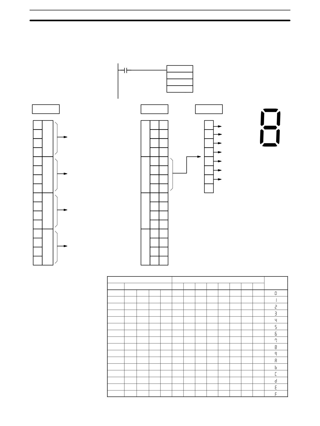
Some example Di values and the 4-bit binary to 7-segment display conversions
that they produce are shown below.
Di: 0011
Di: 0030
S digits
D
S digits
D
0
1st half
0
1st half
1
2nd half
1
2nd half
2
2
3
3
D+1
1st half
2nd half
Di: 0112
Di: 0130
S digits
D
S digits
D
0
0
1st half
1st half
1
1
2nd half
2nd half
2
2
D+1
3
D+1
3
1st half
1st half
2nd half
2nd half
D+2
1st half
2nd half
443
Conversion Instructions
Section
7-20
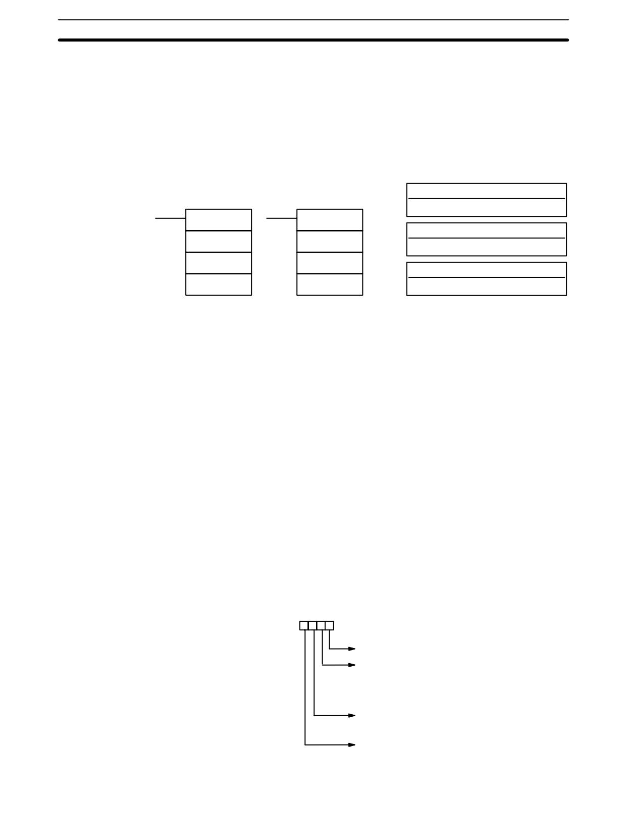
Example
The following example shows the data to produce an 8. The lower case letters
show which bits correspond to which segments of the 7-segment display. The
table underneath shows the original data and converted code for all hexadeci-
mal digits.
00000
@ SDEC(78)
DM 0010
LR 07
200
a
LR 07
DM 0010
IR 200
f
b
g
0
20
0
Bit 00
1
a
1
21
1
1
b
1: Second digit
e
c
x100
0
0
22
0
1
c
0
23
0
1
d
d
0
20
0
1
e
0
21
0
8
1
f
x101
0: One digit
1
0
22
0
1
g
0
23
1
Bit 07
0
0
20
0
0
21
1
x102
0 or 1:
2
0
0
Bits 00 through 07
22
1
1
Bits 08 through 15.
0
23
1
0
20
1
0
x103
3
21
0
Not used.
0
22
1
0
23
1
Original data
Converted code (segments)
Display
Digit
Bits
-
g
f
e
d
c
b
a
0
0
0
0
0
0
0
1
1
0
0
0
0
1
0
0
0
1
0
0
1
1
0
0
0
0
2
0
0
1
0
0
0
1
1
0
0
1
1
3
0
0
1
1
0
0
1
1
0
0
1
1
4
0
1
0
0
0
0
1
1
0
1
0
0
5
0
1
0
1
0
0
1
1
0
1
0
1
6
0
1
1
0
0
0
1
1
0
1
0
1
7
0
1
1
1
0
0
1
1
0
1
1
1
8
1
0
0
0
0
0
1
1
1
0
0
0
9
1
0
0
1
0
0
1
1
1
0
0
1
A
1
0
1
0
0
1
0
0
0
0
0
1
B
1
0
1
1
0
1
0
0
0
0
1
0
C
1
1
0
0
0
1
0
0
0
0
1
1
D
1
1
0
1
0
1
0
0
0
1
0
0
E
1
1
1
0
0
1
0
0
0
1
0
1
F
1
1
1
1
0
1
0
0
0
1
1
0
444
Conversion Instructions
Section
7-20
Flags
ER:
Incorrect digit designator, or data area for destination exceeded.
Indirectly addressed DM word is non-existent. (Content of *DM word is
not BCD, or the DM area boundary has been exceeded.)
7-20-8
ASCII CONVERT - ASC(86)
Operand Data Areas
Ladder Symbols
S: Source word
IR, SR, AR, DM, HR, TC, LR
ASC(86)
@ASC(86)
Di: Digit designator
S
S
IR, SR, AR, DM, HR, TC, LR, #
Di
Di
D: First destination word
D
D
IR, SR, AR, DM, HR, LR
Limitations
Di must be within the values given below.
All destination words must be in the same data area.
DM 6144 to DM 6655 cannot be used for D.
Description
When the execution condition is OFF, ASC(86) is not executed. When the
execution condition is ON, ASC(86) converts the designated digit(s) of S into the
equivalent 8-bit ASCII code and places it into the destination word(s) beginning
with D.
Any or all of the digits in S may be converted in order from the designated first
digit. The first digit, the number of digits to be converted, and the half of D to re-
ceive the first ASCII code (rightmost or leftmost 8 bits) are designated in Di. If
multiple digits are designated, they will be placed in order starting from the des-
ignated half of D, each requiring two digits. If more digits are designated than
remain in S (counting from the designated first digit), further digits will be used
starting back at the beginning of S.
Note Refer to Appendix G for a table of ASCII characters.
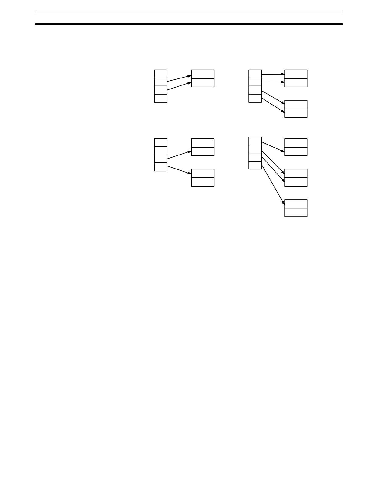
Digit Designator
The digits of Di are set as shown below.
Digit number:
3210
Specifies the first digit to be converted (0 to 3).
Number of digits to be converted (0 to 3)
0: 1 digit
1: 2 digits
2: 3 digits
3: 4 digits
First half of D to be used.
0: Rightmost 8 bits (1st half)
1: Leftmost 8 bits (2nd half)
Parity
0: none
1: even
2: odd
445
Conversion Instructions
Section
7-20
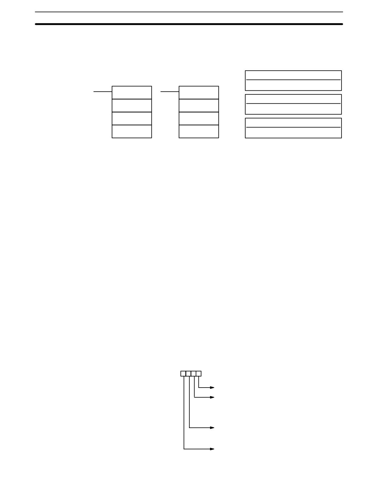
Some examples of Di values and the 4-bit binary to 8-bit ASCII conversions that
they produce are shown below.
Di: 0011
Di: 0030
S
D
S
D
0
1st half
0
1st half
1
2nd half
1
2nd half
2
2
D+1
3
3
1st half
2nd half
Di: 0112
Di: 0130
S
D
S
D
0
0
1st half
1st half
1
1
2nd half
2nd half
2
2
D+1
3
D+1
3
1st half
1st half
2nd half
2nd half
D+2
1st half
2nd half
The leftmost bit of each ASCII character (2 digits) can be automatically adjusted
Parity
for either even or odd parity. If no parity is designated, the leftmost bit will always
be zero.
When even parity is designated, the leftmost bit will be adjusted so that the total
number of ON bits is even, e.g., when adjusted for even parity, ASCII “31”
(00110001) will be “B1” (10110001: parity bit turned ON to create an even num-
ber of ON bits); ASCII “36” (00110110) will be “36” (00110110: parity bit turned
OFF because the number of ON bits is already even). The status of the parity bit
does not affect the meaning of the ASCII code.
When odd parity is designated, the leftmost bit of each ASCII character will be
adjusted so that there is an odd number of ON bits.
Flags
ER:
Incorrect digit designator, or data area for destination exceeded.
Indirectly addressed DM word is non-existent. (Content of *DM word is
not BCD, or the DM area boundary has been exceeded.)
446
Conversion Instructions
Section
7-20
7-20-9
ASCII-TO-HEXADECIMAL - HEX(--)
Operand Data Areas
Ladder Symbols
S: First source word
IR, SR, AR, DM, HR, TC, LR, #
HEX(--)
@HEX(--)
Di: Digit designator
S
S
IR, SR, AR, DM, HR, TC, LR, #
Di
Di
D: Destination word
D
D
IR, SR, AR, DM, HR, LR
Limitations
This instruction is available in the CPM2A/CPM2C/SRM1(-V2) only.
Di must be within the values given below.
All source words must be in the same data area.
Bytes in the source words must contain the ASCII code equivalent of hexadeci-
mal values, i.e., 30 to 39 (0 to 9) or 41 to 46 (A to F).
DM 6144 to DM 6655 cannot be used for D.
When the execution condition is OFF, HEX(--) is not executed. When the
Description
execution condition is ON, HEX(--) converts the designated byte(s) of ASCII
code from the source word(s) into the hexadecimal equivalent and places it into
D.
Up to 4 ASCII codes may be converted beginning with the designated first byte
of S. The converted hexadecimal values are then placed in D in order from the
designated digit. The first byte (rightmost or leftmost 8 bits), the number of bytes
to be converted, and the digit of D to receive the first hexadecimal value are
designated in Di. If multiple bytes are designated, they will be converted in order
starting from the designated half of S and continuing to S+1 and S+2, if
necessary.
If more digits are designated than remain in D (counting from the designated first
digit), further digits will be used starting back at the beginning of D. Digits in D
that do not receive converted data will not be changed.
Digit Designator
The digits of Di are set as shown below.
Digit number:
3210
Specifies the first digit of D to be used (0 to 3).
Number of bytes to be converted (0 to 3)
0: 1 byte (2-digit ASCII code)
1: 2 bytes
2: 3 bytes
3: 4 bytes
First byte of S to be used.
0: Rightmost 8 bits (1st byte)
1: Leftmost 8 bits (2nd byte)
Parity
0: none
1: even
2: odd
447
Conversion Instructions
Section
7-20
Some examples of Di values and the 8-bit ASCII to 4-bit hexadecimal conver-
sions that they produce are shown below.
Di: 0011
Di: 0030
S
D
S
D
1st byte
0
1st byte
0
2nd byte
1
2nd byte
1
2
2
S+1
3
3
1st byte
2nd byte
Di: 0023
Di: 0133
S
D
S
1st byte
0
1st byte
D
2nd byte
1
2nd byte
0
2
1
S+1
S+1
3
2
1st byte
1st byte
3
2nd byte
2nd byte
S+2
1st byte
2nd byte
ASCII Code Table
The following table shows the ASCII codes before conversion and the hexadeci-
mal values after conversion. Refer to Appendix G for a table of ASCII characters.
Original data
Converted data
ASCII Code
Bit status (See note.)
Digit
Bits
30
*
0
1
1
0
0
0
0
0
0
0
0
0
31
*
0
1
1
0
0
0
1
1
0
0
0
1
32
*
0
1
1
0
0
1
0
2
0
0
1
0
33
*
0
1
1
0
0
1
1
3
0
0
1
1
34
*
0
1
1
0
1
0
0
4
0
1
0
0
35
*
0
1
1
0
1
0
1
5
0
1
0
1
36
*
0
1
1
0
1
1
0
6
0
1
1
0
37
*
0
1
1
0
1
1
1
7
0
1
1
1
38
*
0
1
1
1
0
0
0
8
1
0
0
0
39
*
0
1
1
1
0
0
1
9
1
0
0
1
41
*
1
0
1
0
0
0
1
A
1
0
1
0
42
*
1
0
1
0
0
1
0
B
1
0
1
1
43
*
1
0
1
0
0
1
1
C
1
1
0
0
44
*
1
0
1
0
1
0
0
D
1
1
0
1
45
*
1
0
1
0
1
0
1
E
1
1
1
0
46
*
1
0
1
0
1
1
0
F
1
1
1
1
Note The leftmost bit of each ASCII code is adjusted for parity.
The leftmost bit of each ASCII character (2 digits) is automatically adjusted for
Parity
either even or odd parity.
With no parity, the leftmost bit should always be zero. With odd or even parity, the
leftmost bit of each ASCII character should be adjusted so that there is an odd or
even number of ON bits.
If the parity of the ASCII code in S does not agree with the parity specified in Di,
the ER Flag (SR 25503) will be turned ON and the instruction will not be
executed.
448

Conversion Instructions
Section
7-20
Flags
ER:
Incorrect digit designator, or data area for destination exceeded.
The source words do not contain ASCII data that can be converted to
hexadecimal, i.e., values ranging from 0 to 9 or A to F.
Indirectly addressed DM word is non-existent. (Content of *DM word is
not BCD, or the DM area boundary has been exceeded.)
Example
In the following example, the 2nd byte of LR 10 and the 1st byte of LR 11 are con-
verted to hexadecimal values and those values are written to the first and se-
cond bytes of IR 200.
00000
Address
Instruction
Operands
@HEX(--)
LR 10
00000
LD
00000
HR 10
00001
@HEX(--)
LR
10
200
HR
10
200
HR 10
0
1
1
0
LR 12
3
5
3
4
LR 11
4
2
3
2
LR 10
3
1
3
0
Conversion to
hexadecimal
200
0
0
2
1
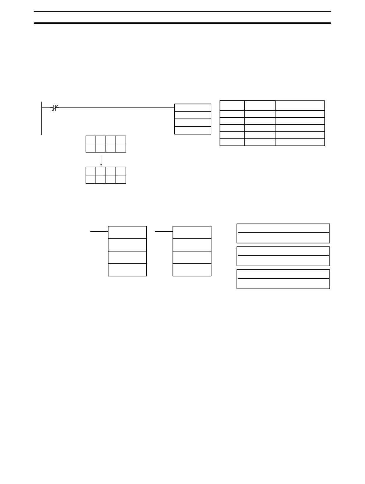
7-20-10 HOURS-TO-SECONDS - SEC(--)
Ladder Symbols
Operand Data Areas
S: Beginning source word (BCD)
SEC(--)
@SEC(--)
IR, SR, AR, DM, HR, TC, LR
S
S
R: Beginning result word (BCD)
R
R
IR, SR, AR, DM, HR, TC, LR
000
000
000: No function
000
Limitations
This instruction is available in the CPM2A/CPM2C only.
S and S+1 must be within the same data area. R and R+1 must be within the
same data area. S and S+1 must be BCD and must be in the proper hours/min-
utes/seconds format.
DM 6144 to DM 6655 cannot be used for R.
Description
SEC(--) is used to convert time notation in hours/minutes/seconds to an equiv-
alent in just seconds.
For the source data, the seconds are designated in bits 00 through 07 and the
minutes are designated in bits 08 through 15 of S. The hours are designated in
S+1. The maximum is thus 9,999 hours, 59 minutes, and 59 seconds.
The result is output to R and R+1. The maximum obtainable value is 35,999,999
seconds.
Flags
ER:
S and S+1 or R and R+1 are not in the same data area.
S and/or S+1 do not contain BCD.
449
Conversion Instructions
Section
7-20
Number of seconds and/or minutes exceeds 59.
Indirectly addressed DM word is non-existent. (Content of *DM word is
not BCD, or the DM area boundary has been exceeded.)
EQ:
ON when the result is zero.
Example
When 00000 is OFF (i.e., when the execution condition is ON), the following
instruction would convert the hours, minutes, and seconds given in HR 12 and
HR 13 to seconds and store the results in DM 0100 and DM 0101 as shown.
00000
Address
Instruction
Operands
SEC(--)
HR 12
00000
LD NOT
00000
DM 0100
00001
SEC(--)
000
HR
12
DM
0100
HR 12
3
2
0
7
2,815 hrs, 32 min,
000
HR 13
2
8
1
5
07 s
DM 0100
5
9
2
7
10,135,927 s
DM 0101
1
0
1
3
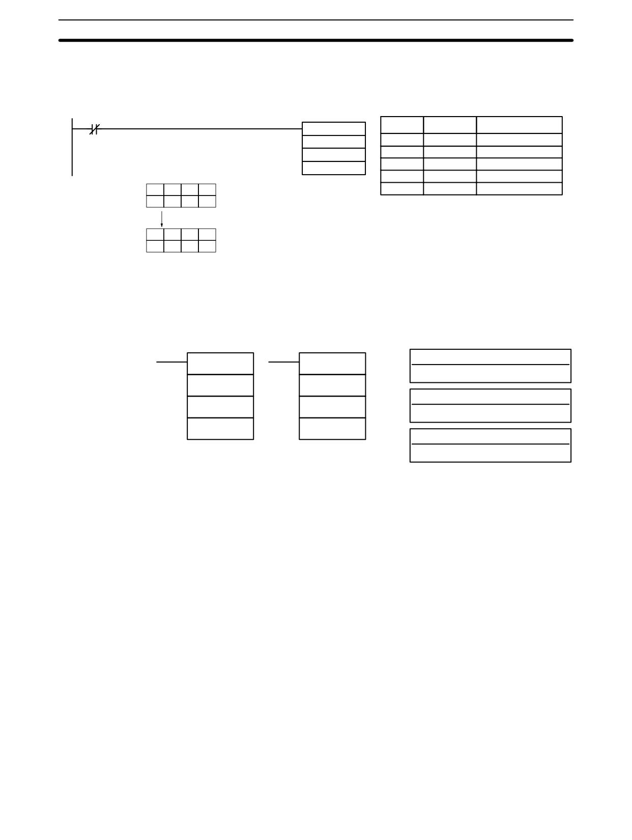
7-20-11 SECONDS-TO-HOURS - HMS(--)
Ladder Symbols
Operand Data Areas
S: Beginning source word (BCD)
HMS(--)
@HMS(--)
IR, SR, AR, DM, HR, TC, LR
S
S
R: Beginning result word (BCD)
R
R
IR, SR, AR, DM, HR, TC, LR
000
000
000: No function
000
Limitations
This instruction is available in the CPM2A/CPM2C only.
S and S+1 must be within the same data area. R and R+1 must be within the
same data area. S and S+1 must be BCD and must be between 0 and
35,999,999 seconds.
DM 6144 to DM 6655 cannot be used for R.
Description
HMS(--) is used to convert time notation in seconds to an equivalent in hours/
minutes/seconds.
The number of seconds designated in S and S+1 is converted to hours/minutes/
seconds and placed in R and R+1.
For the results, the seconds are placed in bits 00 through 07 and the minutes are
placed in bits 08 through 15 of R. The hours are placed in R+1. The maximum is
9,999 hours, 59 minutes, and 59 seconds.
Flags
ER:
S and S+1 or R and R+1 are not in the same data area.
S and/or S+1 do not contain BCD or exceed 36,000,000 seconds.
Indirectly addressed DM word is non-existent. (Content of *DM word is
not BCD, or the DM area boundary has been exceeded.)
EQ:
ON when the result is zero.
450
Conversion Instructions
Section
7-20
Example
When 00000 is OFF (i.e., when the execution condition is ON), the following
instruction would convert the seconds given in HR 12 and HR 13 to hours, min-
utes, and seconds and store the results in DM 0100 and DM 0101 as shown.
00000
Address
Instruction
Operands
HMS(--)
HR 12
00000
LD NOT
00000
00001
HMS(--)
DM 0100
HR
12
000
DM
0100
000
HR 12
5
9
2
7
10,135,927 s
HR 13
1
0
1
3
DM 0100
3
2
0
7
2,815 hrs, 32 min, 07 s
DM 0101
2
8
1
5
7-20-12
2’S COMPLEMENT - NEG(--)
Ladder Symbols
Operand Data Areas
S: Source word
NEG(--)
@NEG(--)
IR, SR, AR, DM, HR, TC, LR, #
S
S
R: Result word
R
R
IR, SR, AR, DM, HR, LR
000
000
000
Not used. Set to 000.
Limitations
This instruction is available in the CPM2A/CPM2C/SRM1(-V2) only.
DM 6144 to DM 6655 cannot be used for R.
Converts the four-digit hexadecimal content of the source word (S) to its 2’s
Description
complement and outputs the result to the result word (R). This operation is effec-
tively the same as subtracting S from 0000 and outputting the result to R; it will
calculate the absolute value of negative signed binary data.
If the content of S is 0000, the content of R will also be 0000 after execution and
EQ (SR 25506) will be turned on.
If the content of S is 8000, the content of R will also be 8000 after execution and
UF (SR 25405) will be turned on.
Note Refer to 2-16 Calculating with Signed Binary Data for more details.
Flags
ER:
Indirectly addressed DM word is non-existent. (Content of *DM word is
not BCD, or the DM area boundary has been exceeded.)
EQ:
ON when the content of R is zero after execution; otherwise OFF.
UF:
ON when the content of S is 8000; otherwise OFF.
N:
ON when bit 15 of R is ON; otherwise OFF.
451
Conversion Instructions
Section
7-20
Example
The following example shows how to use NEG(--) to find the 2’s complement of
the content of DM 0005 and output the result to IR 105.
00100
Address
Instruction
Operands
NEG(--)
DM 0005
00000
LD
00100
105
00001
NEG(--)
DM
0005
000
105
000
#0000
#001F
Content of DM 0005.
-
#FFE1
Output to IR 105.
452
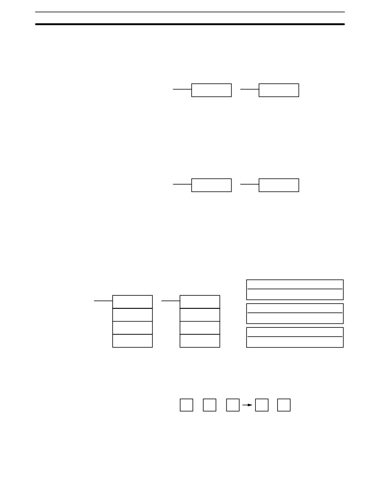
BCD Calculation Instructions
Section
7-21
7-21 BCD Calculation Instructions
7-21-1
SET CARRY - STC(40)
Ladder Symbols
STC(40)
@STC(40)
When the execution condition is OFF, STC(40) is not executed. When the
execution condition is ON, STC(40) turns ON CY (SR 25504).
Note Refer to Appendix B Error and Arithmetic Flag Operation for a table listing the
instructions that affect CY.
7-21-2
CLEAR CARRY - CLC(41)
Ladder Symbols
CLC(41)
@CLC(41)
When the execution condition is OFF, CLC(41) is not executed. When the
execution condition is ON, CLC(41) turns OFF CY (SR 25504).
CLEAR CARRY is used to reset (turn OFF) CY (SR 25504) to “0.”
Note Refer to Appendix B Error and Arithmetic Flag Operation for a table listing the
instructions that affect CY.
7-21-3
BCD ADD - ADD(30)
Operand Data Areas
Ladder Symbols
Au: Augend word (BCD)
IR, SR, AR, DM, HR, TC, LR, #
ADD(30)
@ADD(30)
Ad: Addend word (BCD)
Au
Au
IR, SR, AR, DM, HR, TC, LR, #
Ad
Ad
R: Result word
R
R
IR, SR, AR, DM, HR, LR
Limitations
DM 6144 to DM 6655 cannot be used for R.
Description
When the execution condition is OFF, ADD(30) is not executed. When the
execution condition is ON, ADD(30) adds the contents of Au, Ad, and CY, and
places the result in R. CY will be set if the result is greater than 9999.
Au
+
Ad
+
CY
CY
R
Flags
ER:
Au and/or Ad is not BCD.
Indirectly addressed DM word is non-existent. (Content of *DM word is
not BCD, or the DM area boundary has been exceeded.)
CY:
ON when there is a carry in the result.
EQ:
ON when the result is 0.
453
BCD Calculation Instructions
Section
7-21
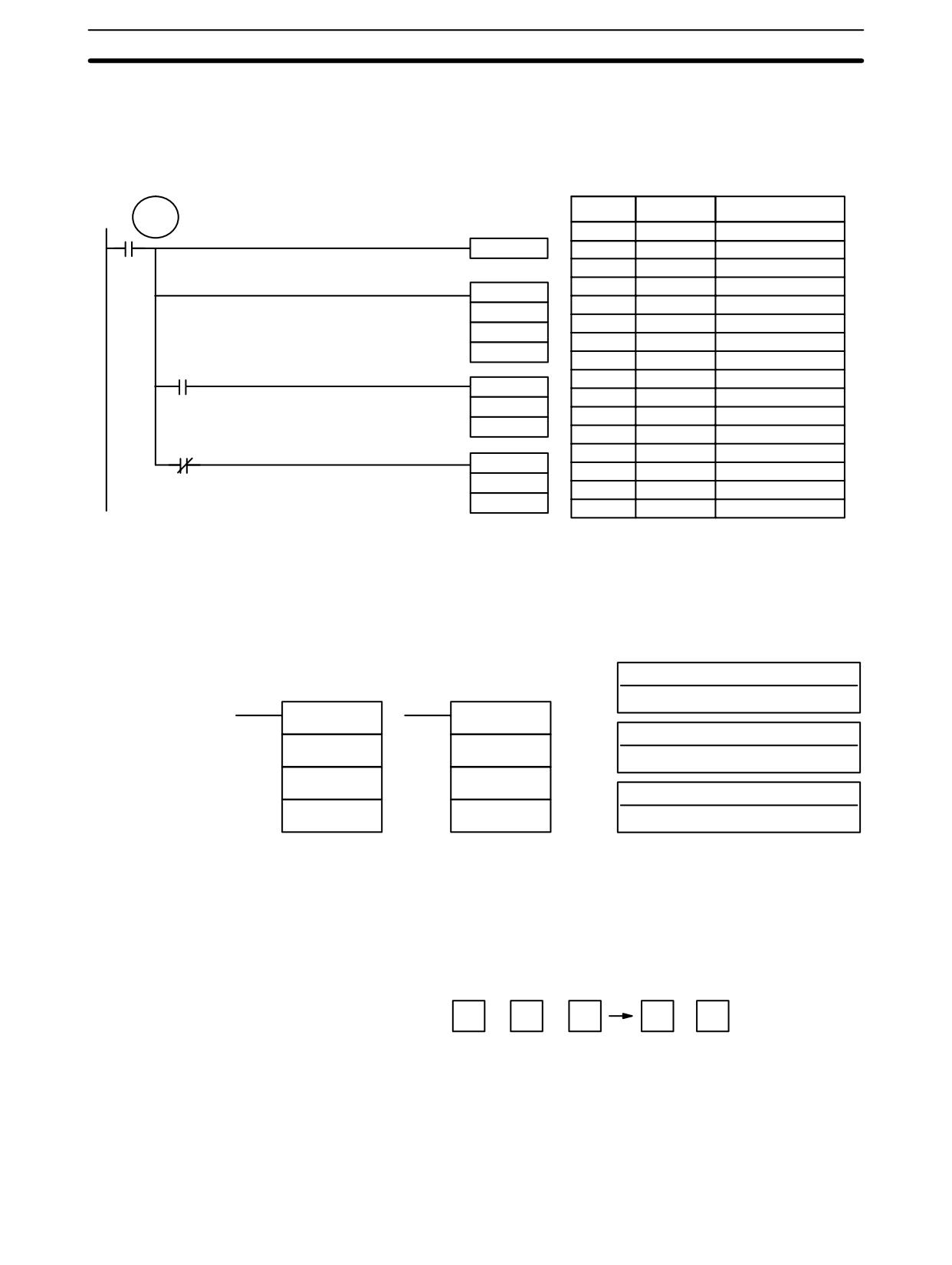
If 00002 is ON, the program represented by the following diagram clears CY with
Example
CLC(41), adds the content of IR 200 to a constant (6103), places the result in DM
0100, and then moves either all zeros or 0001 into DM 0101 depending on the
status of CY (25504). This ensures that any carry from the last digit is preserved
in R+1 so that the entire result can be later handled as eight-digit data.
Address
Instruction
Operands
TR 0
00002
00000
LD
00002
CLC(41)
00001
OUT
TR
0
00002
CLC(41)
00003
ADD(30)
ADD(30)
200
200
#
6103
#6103
DM
0100
DM 0100
00004
AND
25504
25504
00005
MOV(21)
MOV(21)
#
0001
#0001
DM
0101
DM 0101
00006
LD
TR
0
25504
00007
AND NOT
25504
MOV(21)
00008
MOV(21)
#0000
#
0000
DM 0101
DM
0101
Although two ADD(30) can be used together to perform eight-digit BCD addition,
ADDL(54) is designed specifically for this purpose.
7-21-4
BCD SUBTRACT - SUB(31)
Operand Data Areas
Ladder Symbols
Mi: Minuend word (BCD)
IR, SR, AR, DM, HR, TC, LR, #
SUB(31)
@SUB(31)
Su: Subtrahend word (BCD)
Mi
Mi
IR, SR, AR, DM, HR, TC, LR, #
Su
Su
R: Result word
R
R
IR, SR, AR, DM, HR, LR
Limitations
DM 6144 to DM 6655 cannot be used for R.
Description
When the execution condition is OFF, SUB(31) is not executed. When the
execution condition is ON, SUB(31) subtracts the contents of Su and CY from
Mi, and places the result in R. If the result is negative, CY is set and the 10’s com-
plement of the actual result is placed in R. To convert the 10’s complement to the
true result, subtract the content of R from zero (see example below).
Mi
-
Su
-
CY
CY
R
Flags
ER:
Mi and/or Su is not BCD.
Indirectly addressed DM word is non-existent. (Content of *DM word is
not BCD, or the DM area boundary has been exceeded.)
CY:
ON when the result is negative, i.e., when Mi is less than Su plus CY.
EQ:
ON when the result is 0.
454
BCD Calculation Instructions
Section 7-21
!
Caution Be sure to clear the carry flag with CLC(41) before executing SUB(31) if its pre-
vious status is not required, and check the status of CY after doing a subtraction
with SUB(31). If CY is ON as a result of executing SUB(31) (i.e., if the result is
negative), the result is output as the 10’s complement of the true answer. To con-
vert the output result to the true value, subtract the value in R from 0.
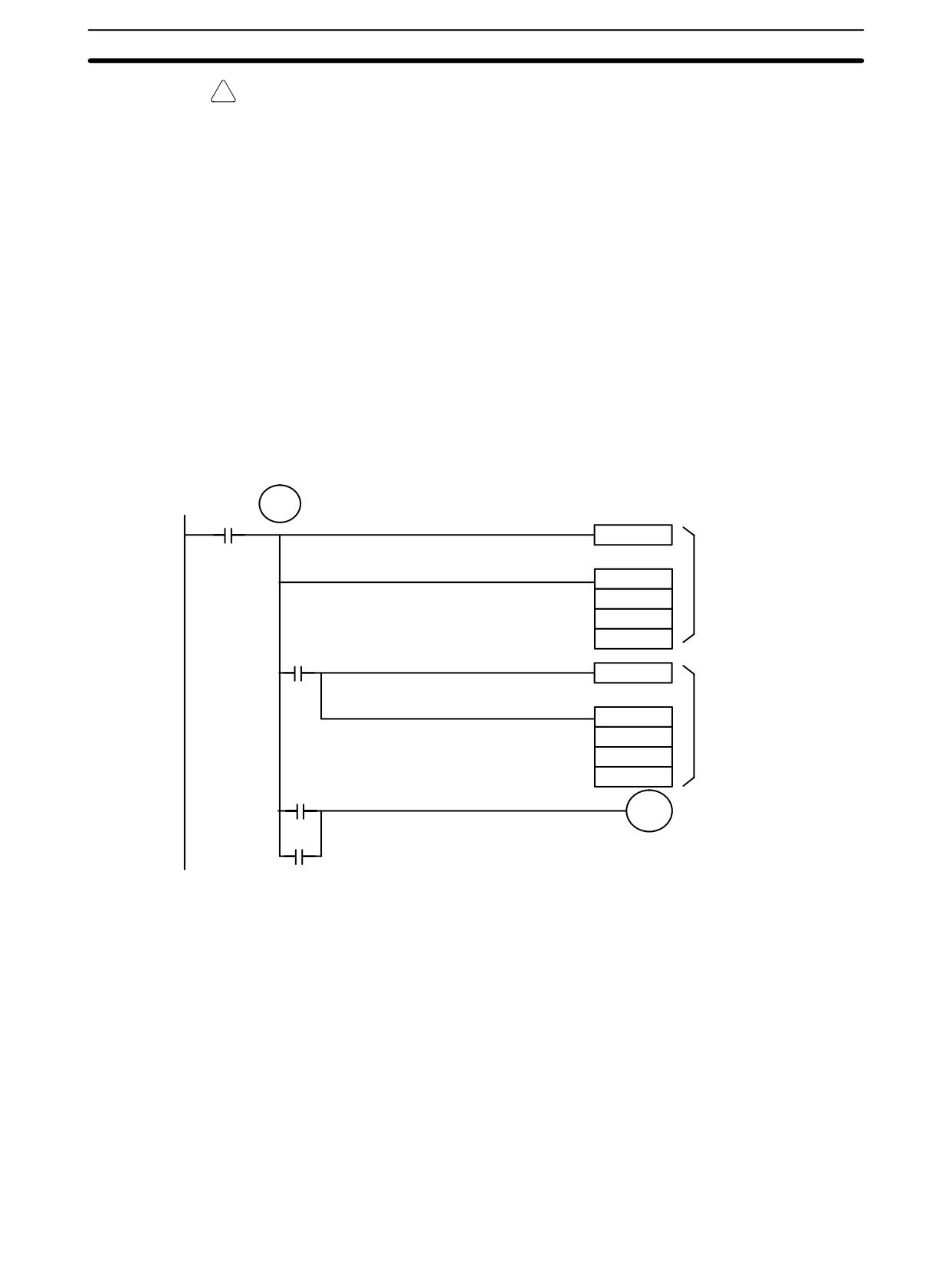
Example
When 00002 is ON, the following ladder program clears CY, subtracts the con-
tents of DM 0100 and CY from the content of 201 and places the result in HR 10.
If CY is set by executing SUB(31), the result in HR 10 is subtracted from zero
(note that CLC(41) is again required to obtain an accurate result), the result is
placed back in HR 10, and HR 1100 is turned ON to indicate a negative result.
If CY is not set by executing SUB(31), the result is positive, the second subtrac-
tion is not performed, and HR 1100 is not turned ON. HR 1100 is programmed as
a self-maintaining bit so that a change in the status of CY will not turn it OFF
when the program is rescanned.
In this example, differentiated forms of SUB(31) are used so that the subtraction
operation is performed only once each time 00002 is turned ON. When another
subtraction operation is to be performed, 00002 will need to be turned OFF for at
least one cycle (resetting HR 1100) and then turned back ON.
TR 0
00002
CLC(41)
@SUB(31)
First
subtraction
201
DM 0100
HR 10
25504
CLC(41)
@SUB(31)
Second
subtraction
#0000
HR 10
HR 10
25504
HR 1100
HR 1100
Turned ON to indicate
negative result.
455
BCD Calculation Instructions
Section
7-21
Address
Instruction
Operands
00000
LD
00002
00001
OUT
TR
0
00002
CLC(41)
00003
@SUB(31)
201
DM
0100
HR
10
00004
AND
25504
00005
CLC(41)
00006
@SUB(31)
#
0000
HR
10
HR
10
00007
LD
TR
0
00008
LD
25504
00009
OR
HR
1100
00010
AND LD
---
00011
OUT
HR
1100
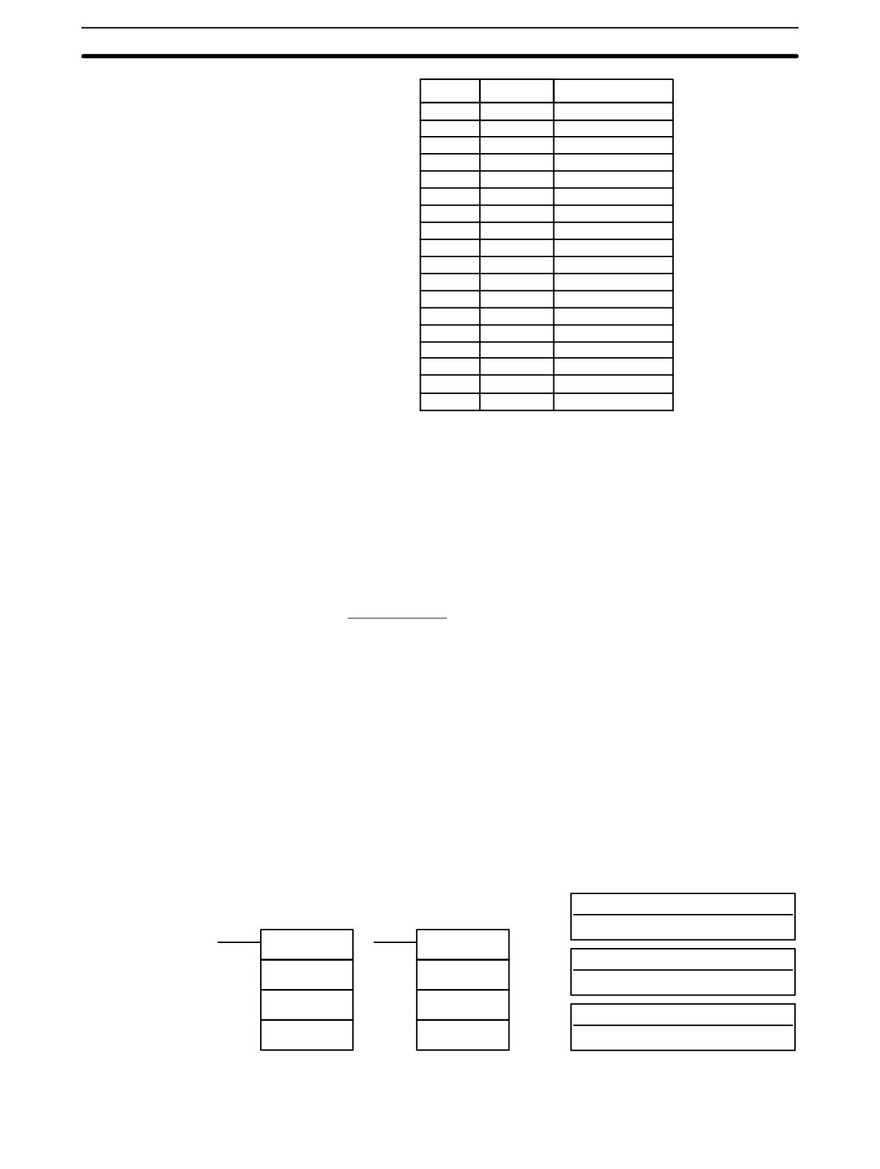
The first and second subtractions for this diagram are shown below using exam-
ple data for 201 and DM 0100.
Note The actual SUB(31) operation involves subtracting Su and CY from 10,000 plus
Mi. For positive results the leftmost digit is truncated. For negative results the
10s complement is obtained. The procedure for establishing the correct answer
is given below.
First Subtraction
IR 201
1029
DM 0100
- 3452
CY
- 0
HR 10
7577 (1029 + (10000 - 3452))
CY
1
(negative result)
Second Subtraction
0000
HR 10 -7577
CY -0
HR 10 2423
(0000 + (10000 - 7577))
CY
1
(negative result)
In the above case, the program would turn ON HR 1100 to indicate that the value
held in HR 10 is negative.
7-21-5
BCD MULTIPLY - MUL(32)
Operand Data Areas
Ladder Symbols
Md: Multiplicand (BCD)
IR, SR, AR, DM, HR, TC, LR, #
MUL(32)
@MUL(32)
Mr: Multiplier (BCD)
Md
Md
IR, SR, AR, DM, HR, TC, LR, #
Mr
Mr
R: First result word
R
R
IR, SR, AR, DM, HR LR
Limitations
DM 6144 to DM 6655 cannot be used for R.
456
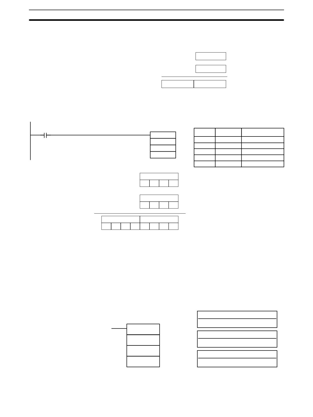
BCD Calculation Instructions
Section
7-21
When the execution condition is OFF, MUL(32) is not executed. When the
Description
execution condition is ON, MUL(32) multiplies Md by the content of Mr, and
places the result In R and R+1.
Md
X
Mr
R +1
R
When IR 00000 is ON with the following program, the contents of IR 013 and
Example
DM 0005 are multiplied and the result is placed in HR 07 and HR 08. Example
data and calculations are shown below the program.
00000
Address
Instruction
Operands
MUL(32)
00000
LD
00000
013
00001
MUL(32)
DM 0005
013
HR 07
DM
0005
HR
07
Md: IR 013
3
3
5
6
Mr: DM 0005
X
0
0
2
5
R+1: HR 08
R: HR 07
0
0
0
8
3
9
0
0
Flags
ER:
Md and/or Mr is not BCD.
Indirectly addressed DM word is non-existent. (Content of *DM word is
not BCD, or the DM area boundary has been exceeded.)
CY:
ON when there is a carry in the result.
EQ:
ON when the result is 0.
7-21-6
BCD DIVIDE - DIV(33)
Operand Data Areas
Ladder Symbol
Dd: Dividend word (BCD)
IR, SR, AR, DM, HR, TC, LR, #
DIV(33)
Dr: Divisor word (BCD)
Dd
IR, SR, AR, DM, HR, TC, LR, #
Dr
R: First result word (BCD)
R
IR, SR, AR, DM, HR, LR
R and R+1 must be in the same data area. DM 6144 to DM 6655 cannot be used
Limitations
for R.
457
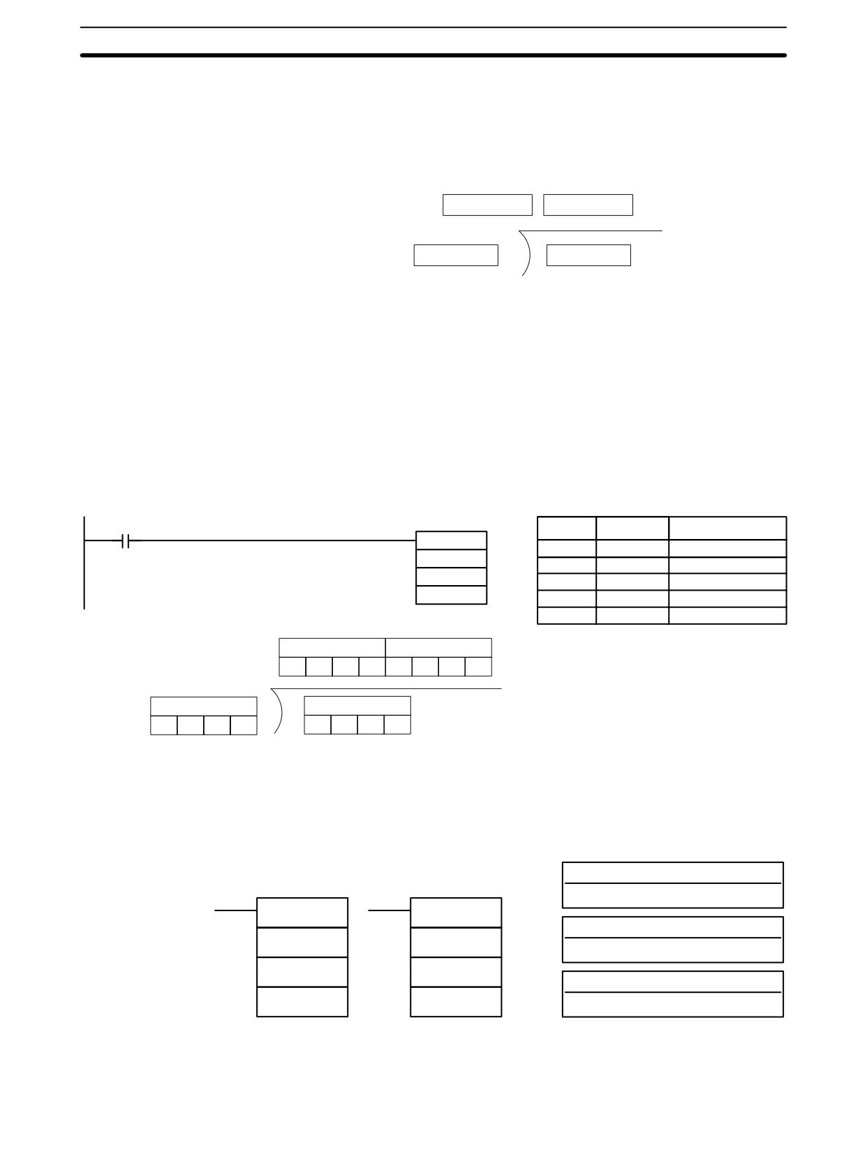
BCD Calculation Instructions
Section
7-21
Description
When the execution condition is OFF, DIV(33) is not executed and the program
moves to the next instruction. When the execution condition is ON, Dd is divided
by Dr and the result is placed in R and R + 1: the quotient in R and the remainder
in R + 1.
Remainder
Quotient
R+1
R
Dr
Dd
Flags
ER:
Dd or Dr is not in BCD.
Indirectly addressed DM word is non-existent. (Content of *DM word is
not BCD, or the DM area boundary has been exceeded.)
EQ:
ON when the result is 0.
Example
When IR 00000 is ON with the following program, the content of IR 216 is divided
by the content of HR 09 and the result is placed in DM 0017 and DM 0018. Exam-
ple data and calculations are shown below the program.
00000
Address
Instruction
Operands
DIV(33)
00000
LD
00000
216
00001
DIV(33)
HR 09
216
DM 0017
HR
09
DM
0017
Quotient
Remainder
R: DM 0017
R + 1: DM 0018
1
1
5
0
0
0
0
2
Dd: HR 09
Dd: IR 216
0
0
0
3
3
4
5
2
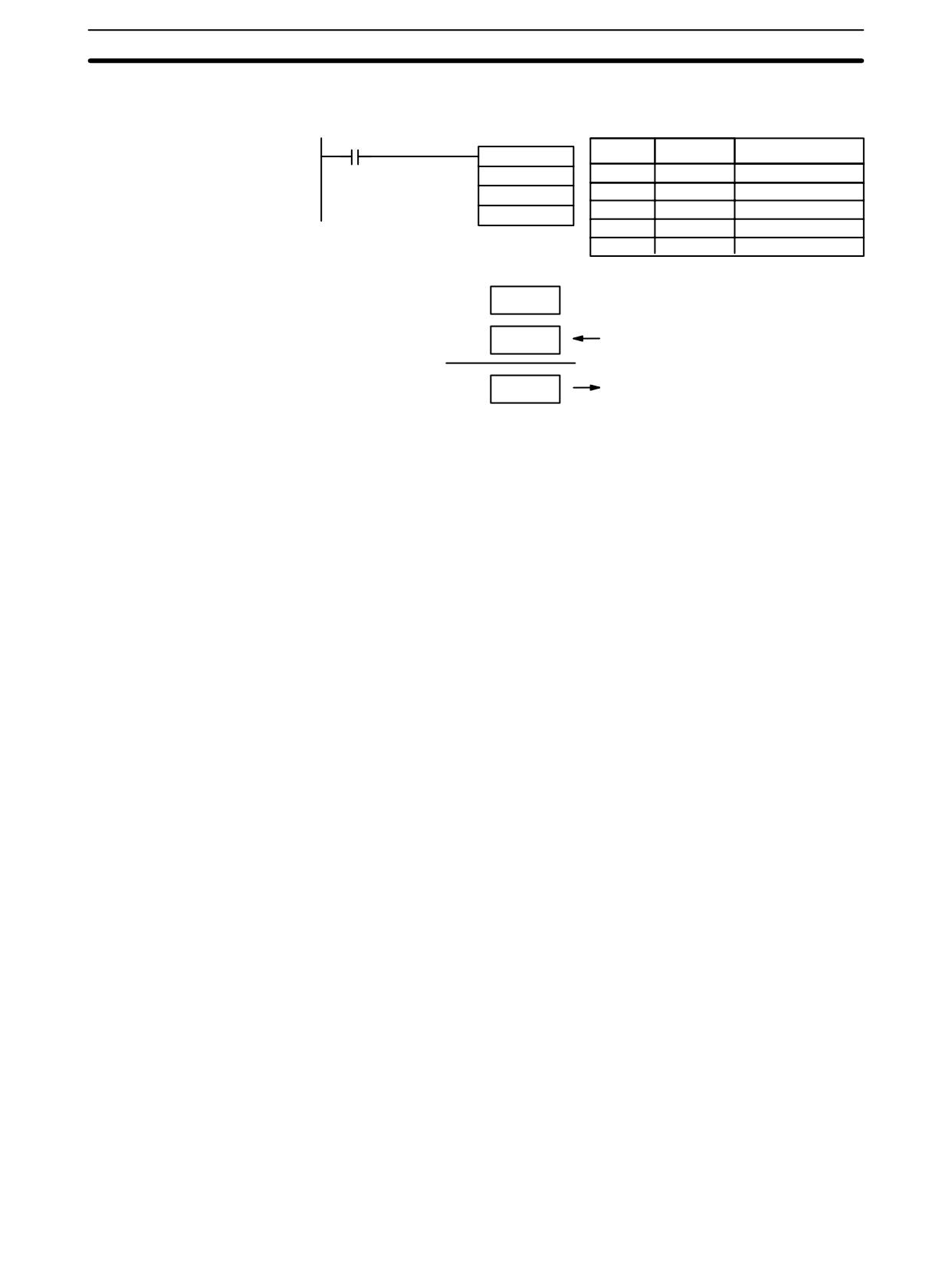
7-21-7
DOUBLE BCD ADD - ADDL(54)
Operand Data Areas
Ladder Symbols
Au: First augend word (BCD)
IR, SR, AR, DM, HR, TC, LR
ADDL(54)
@ADDL(54)
Ad: First addend word (BCD)
Au
Au
IR, SR, AR, DM, HR, TC, LR
Ad
Ad
R: First result word
R
R
IR, SR, AR, DM, HR, LR
Limitations
DM 6144 to DM 6655 cannot be used for R.
458
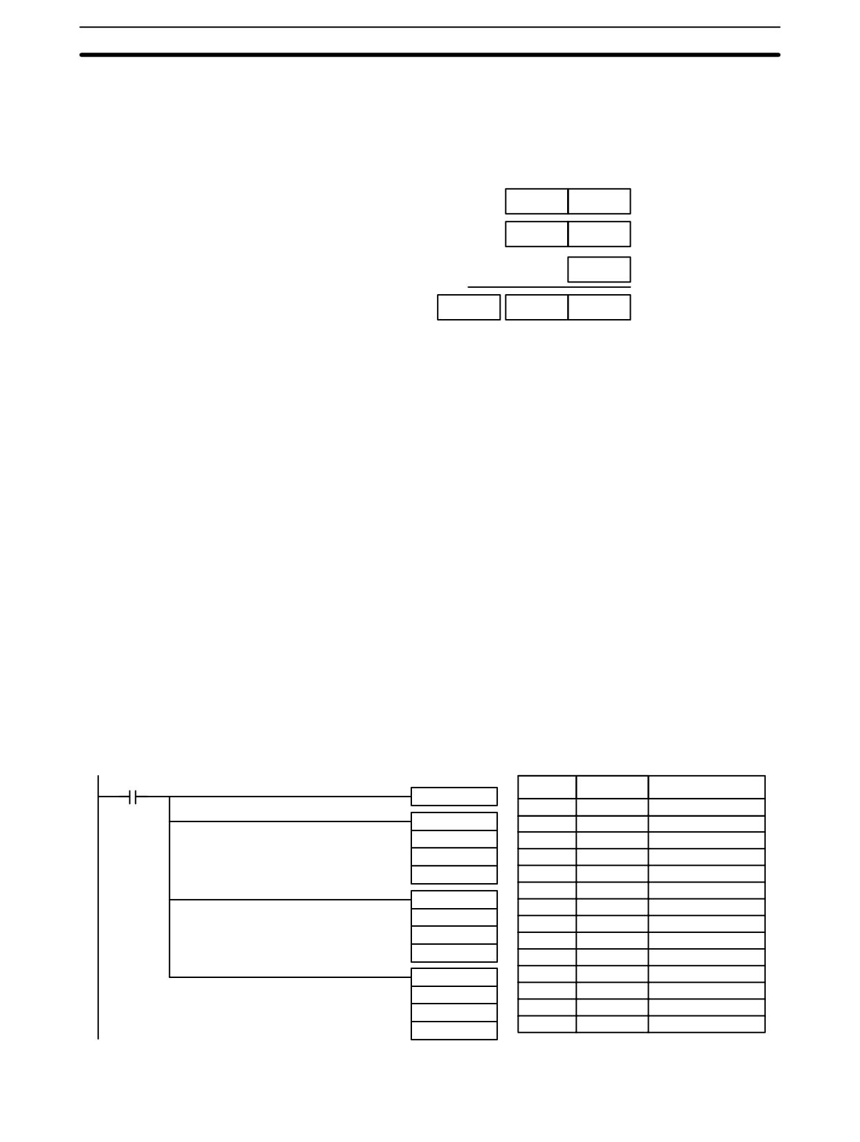
BCD Calculation Instructions
Section
7-21
Description
When the execution condition is OFF, ADDL(54) is not executed. When the
execution condition is ON, ADDL(54) adds the contents of CY to the 8-digit val-
ue in Au and Au+1 to the 8-digit value in Ad and Ad+1, and places the result in R
and R+1. CY will be set if the result is greater than 99999999.
Au + 1
Au
Ad + 1
Ad
CY
+
CY
R + 1
R
Flags
ER:
Au and/or Ad is not BCD.
Indirectly addressed DM word is non-existent. (Content of *DM word is
not BCD, or the DM area boundary has been exceeded.)
CY:
ON when there is a carry in the result.
EQ:
ON when the result is 0.
Example
When 00000 is ON, the following program section adds two 12-digit numbers,
the first contained in LR 00 through LR 02 and the second in DM 0010 through
DM 0012. The result is placed in HR 10 through HR 13.
The rightmost 8 digits of the two numbers are added using ADDL(54), i.e., the
contents of LR 00 and LR 01 are added to DM 0010 and DM 0011 and the results
is placed in HR 10 and HR 11. The second addition adds the leftmost 4 digits of
each number using ADD(30), and includes any carry from the first addition. The
last instruction, ADB(50) (see 7-22-1 BINARY ADD - ADB(50)) adds two all-
zero constants to place any carry from the second addition into HR 13.
00000
Address
Instruction
Operands
CLC(41)
00000
LD
00000
@ADDL(54)
00001
CLC(41)
LR 00
00002
@ADDL(54)
DM 0010
LR
00
HR 10
DM
0010
HR
10
@ADD(30)
00003
@ADD(30)
LR 02
LR
02
DM 0012
DM
0012
HR 12
HR
12
00004
@ADB(50)
@ADB(50)
#
0000
#0000
#
0000
#0000
HR
13
HR 13
459
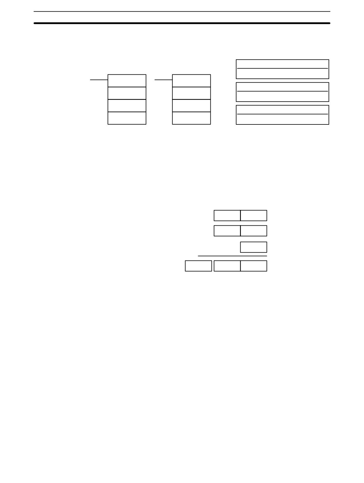
BCD Calculation Instructions
Section
7-21
7-21-8
DOUBLE BCD SUBTRACT - SUBL(55)
Operand Data Areas
Ladder Symbols
Mi: First minuend word (BCD)
IR, SR, AR, DM, HR, TC, LR, #
SUBL(55)
@SUBL(55)
Su: First subtrahend word (BCD)
Mi
Mi
IR, SR, AR, DM, HR, TC, LR, #
Su
Su
R: First result word
R
R
IR, SR, AR, DM, HR, LR
Limitations
DM 6144 to DM 6655 cannot be used for R.
Description
When the execution condition is OFF, SUBL(55) is not executed. When the
execution condition is ON, SUBL(55) subtracts CY and the 8-digit contents of Su
and Su+1 from the 8-digit value in Mi and Mi+1, and places the result in R and
R+1. If the result is negative, CY is set and the 10’s complement of the actual
result is placed in R. To convert the 10’s complement to the true result, subtract
the content of R from zero. Since an 8-digit constant cannot be directly entered,
use the BSET(71) instruction (see 7-17-4 BLOCK SET - BSET(71)) to create an
8-digit constant.
Mi + 1
Mi
Su + 1
Su
CY
–
CY
R + 1
R
Flags
ER:
Mi, M+1,Su, or Su+1 are not BCD.
Indirectly addressed DM word is non-existent. (Content of *DM word is
not BCD, or the DM area boundary has been exceeded.)
CY:
ON when the result is negative, i.e., when Mi is less than Su.
EQ:
ON when the result is 0.
460
BCD Calculation Instructions
Section
7-21
Example
The following example works much like that for single-word subtraction. In this
example, however, BSET(71) is required to clear the content of DM 0000 and
DM 0001 so that a negative result can be subtracted from 0 (inputting an 8-digit
constant is not possible).
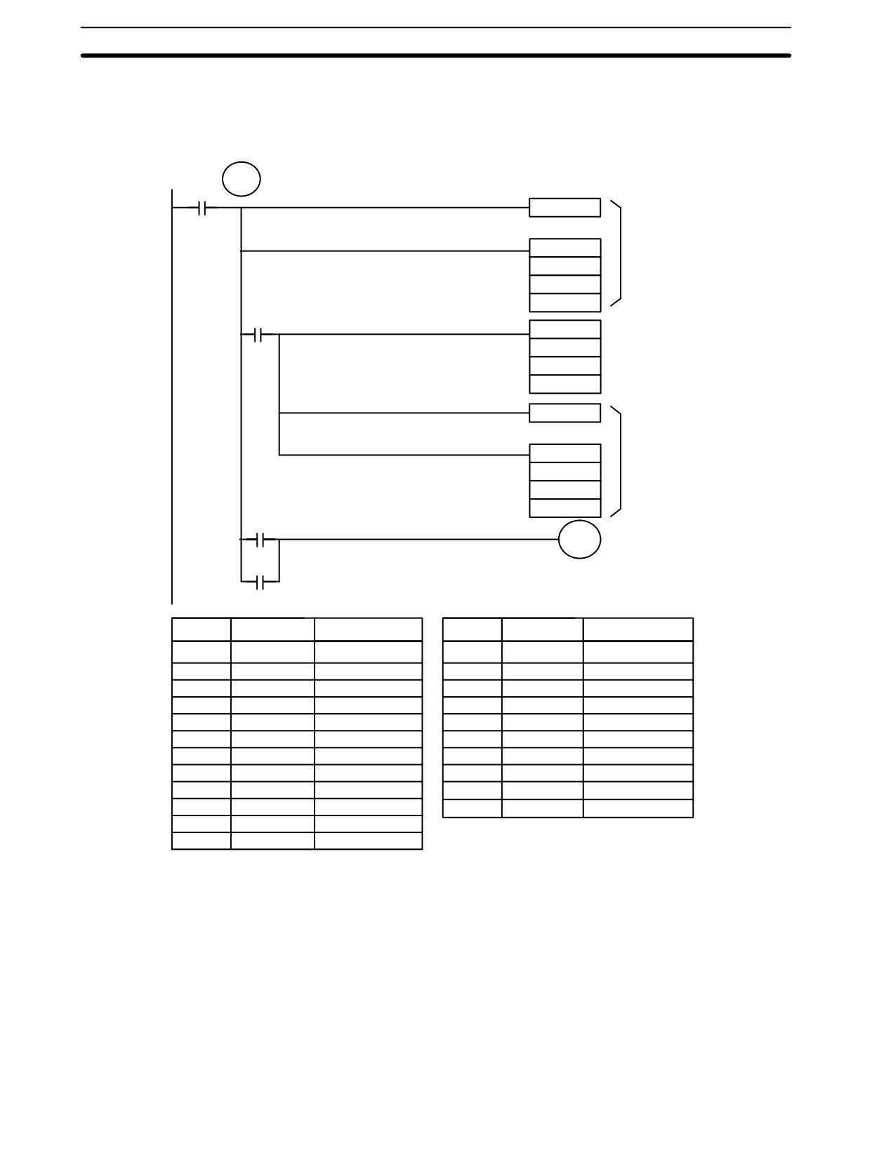
TR 0
00003
CLC(41)
@SUBL(55)
First
HR 00
subtraction
220
DM 0100
25504
@BSET(71)
#0000
DM 0000
DM 0001
CLC(41)
@SUBL(55)
Second
DM 0000
subtraction
DM 0100
DM 0100
25504
HR 0100
HR 0100
Turned ON to indicate
negative result.
Address
Instruction
Operands
Address
Instruction
Operands
00000
LD
00003
00006
CLC(41)
00001
OUT
TR
0
00007
@SUBL(55)
00002
CLC(41)
DM
0000
00003
@SUBL(55)
DM
0100
HR
00
DM
0100
220
00008
LD
TR
0
DM
0100
00009
LD
25504
00004
AND
25504
00010
OR
HR
0100
00005
@BSET(71)
00011
AND LD
#
0000
00012
OUT
HR
0100
DM
0000
DM
0001
461
BCD Calculation Instructions
Section
7-21
7-21-9
DOUBLE BCD MULTIPLY - MULL(56)
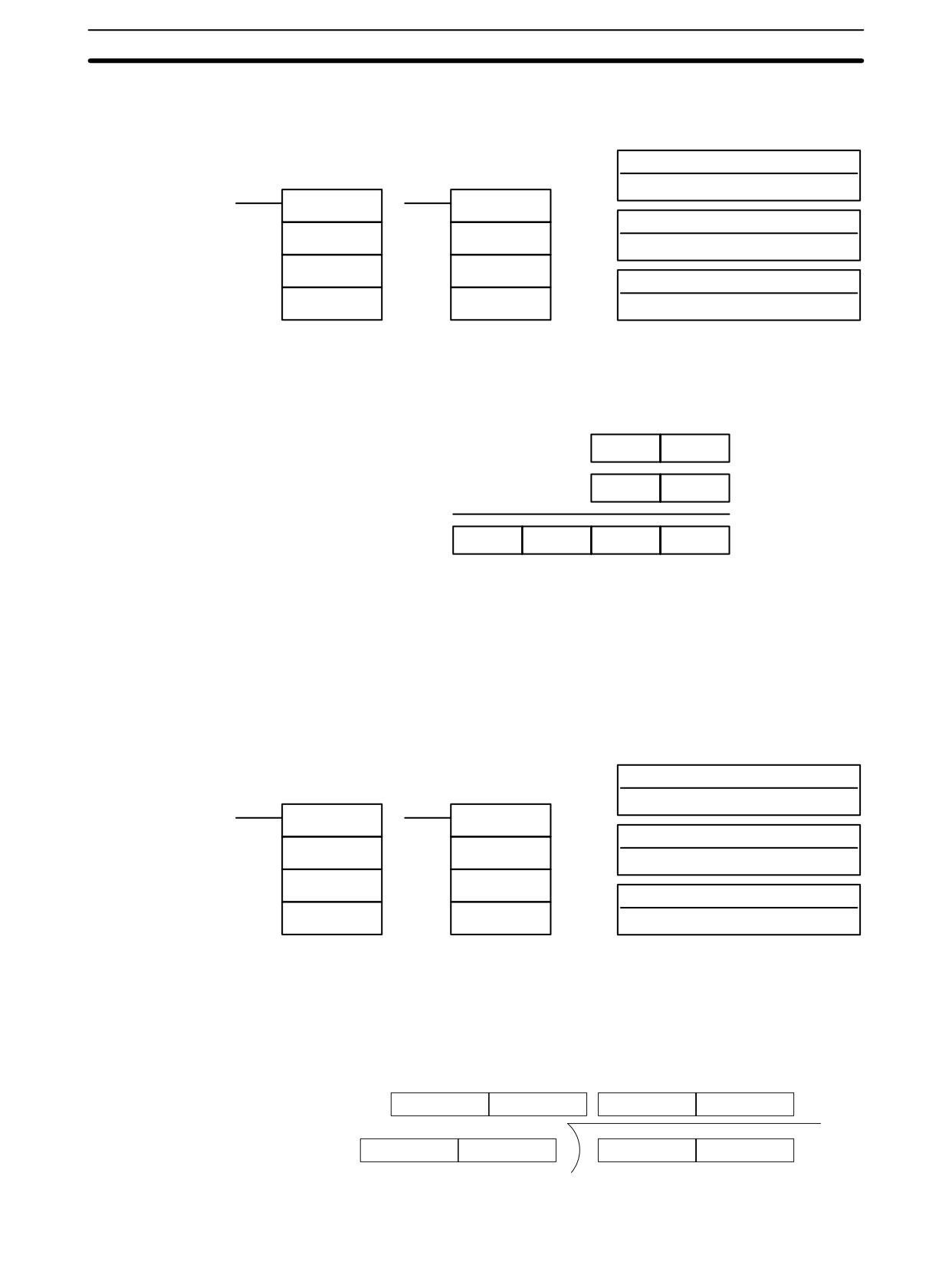
Operand Data Areas
Ladder Symbols
Md: First multiplicand word (BCD)
IR, SR, AR, DM, HR, TC, LR
MULL(56)
@MULL(56)
Mr: First multiplier word (BCD)
Md
Md
IR, SR, AR, DM, HR, TC, LR
Mr
Mr
R: First result word
R
R
IR, SR, AR, DM, HR LR
Limitations
DM 6144 to DM 6655 cannot be used for R.
Description
When the execution condition is OFF, MULL(56) is not executed. When the
execution condition is ON, MULL(56) multiplies the eight-digit content of Md and
Md+1 by the content of Mr and Mr+1, and places the result in R to R+3.
Md + 1
Md
Mr + 1
Mr
x
R + 3
R + 2
R + 1
R
Flags
ER:
Md, Md+1,Mr, or Mr+1 is not BCD.
Indirectly addressed DM word is non-existent. (Content of *DM word is
not BCD, or the DM area boundary has been exceeded.)
CY:
ON when there is a carry in the result.
EQ:
ON when the result is 0.
7-21-10 DOUBLE BCD DIVIDE - DIVL(57)
Operand Data Areas
Ladder Symbols
Dd: First dividend word (BCD)
IR, SR, AR, DM, HR, TC, LR
DIVL(57)
@DIVL(57)
Dr: First divisor word (BCD)
Dd
Dd
IR, SR, AR, DM, HR, TC, LR
Dr
Dr
R: First result word
R
R
IR, SR, AR, DM, HR LR
Limitations
DM 6144 to DM 6655 cannot be used for R.
Description
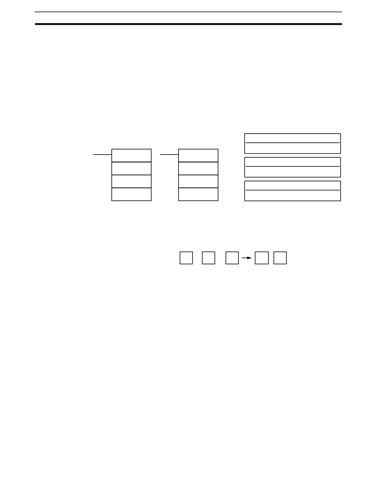
When the execution condition is OFF, DIVL(57) is not executed. When the
execution condition is ON, DIVL(57) the eight-digit content of Dd and D+1 is di-
vided by the content of Dr and Dr+1 and the result is placed in R to R+3: the quo-
tient in R and R+1, the remainder in R+2 and R+3.
Remainder
Quotient
R+3
R+2
R+1
R
Dr+1
Dr
Dd+1
Dd
462
Binary Calculation Instructions
Section
7-22
Flags
ER:
Dr and Dr+1 contain 0.
Dd, Dd+1, Dr, or Dr+1 is not BCD.
Indirectly addressed DM word is non-existent. (Content of *DM word is
not BCD, or the DM area boundary has been exceeded.)
EQ:
ON when the result is 0.
7-22 Binary Calculation Instructions
7-22-1 BINARY ADD - ADB(50)
Operand Data Areas
Ladder Symbols
Au: Augend word (binary)
IR, SR, AR, DM, HR, TC, LR, #
ADB(50)
@ADB(50)
Ad: Addend word (binary)
Au
Au
IR, SR, AR, DM, HR, TC, LR, #
Ad
Ad
R: Result word
R
R
IR, SR, AR, DM, HR, LR
Limitations
DM 6144 to DM 6655 cannot be used for R.
Description
When the execution condition is OFF, ADB(50) is not executed. When the
execution condition is ON, ADB(50) adds the contents of Au, Ad, and CY, and
places the result in R. CY will be set if the result is greater than FFFF.
Au
+
Ad
+
CY
CY
R
ADB(50) can also be used to add signed binary data. With the CPM1A, CPM2A,
CPM2C, and SRM1(-V2), the underflow and overflow flags (SR 25404 and
SR 25405) indicate whether the result has exceeded the lower or upper limits of
the 16-bit signed binary data range.
Flags
ER:
Indirectly addressed DM word is non-existent. (Content of *DM word is
not BCD, or the DM area boundary has been exceeded.)
CY:
ON when the result is greater than FFFF.
EQ:
ON when the result is 0.
OF:
ON when the result exceeds +32,767 (7FFF).
UF:
ON when the result is below -32,768 (8000).
463
Binary Calculation Instructions
Section
7-22
Example
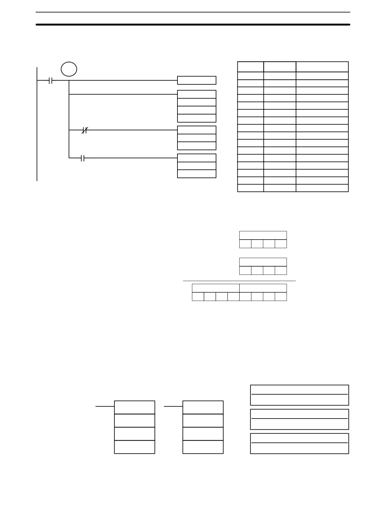
The following example shows a four-digit addition with CY used to place either
#0000 or #0001 into R+1 to ensure that any carry is preserved.
TR 0
Address
Instruction
Operands
00000
00000
LD
00000
CLC(41)
00001
OUT
TR
0
00002
CLC(41)
ADB(50)
00003
ADB(50)
200
200
DM 0100
DM
0100
HR 10
= R
HR
10
25504
00004
AND NOT
25504
MOV(21)
00005
MOV(21)
#0000
#
0000
HR 11
= R+1
25504
HR
11
MOV(21)
00006
LD
TR
0
#0001
00007
AND
25504
HR 11
= R+1
00008
MOV(21)
#
00001
HR
11
In the case below, A6E2 + 80C5 = 127A7. The result is a 5-digit number, so CY
(SR 25504) = 1, and the content of R + 1 becomes #0001.
Au: IR 200
A
6
E
2
Ad: DM 0100
+
8
0
C
5
R+1: HR 11
R: HR 10
0
0
0
1
2
7
A
7
Note For signed binary calculations, the status of the UF and OF flags indicate wheth-
er the result has exceeded the signed binary data range (-32,768 (8000) to
+32,767 (7FFF)).
7-22-2 BINARY SUBTRACT - SBB(51)
Operand Data Areas
Ladder Symbols
Mi: Minuend word (binary)
IR, SR, AR, DM, HR, TC, LR, #
SBB(51)
@SBB(51)
Su: Subtrahend word (binary)
Mi
Mi
IR, SR, AR, DM, HR, TC, LR, #
Su
Su
R: Result word
R
R
IR, SR, AR, DM, HR, LR
Limitations
DM 6144 to DM 6655 cannot be used for R.
464
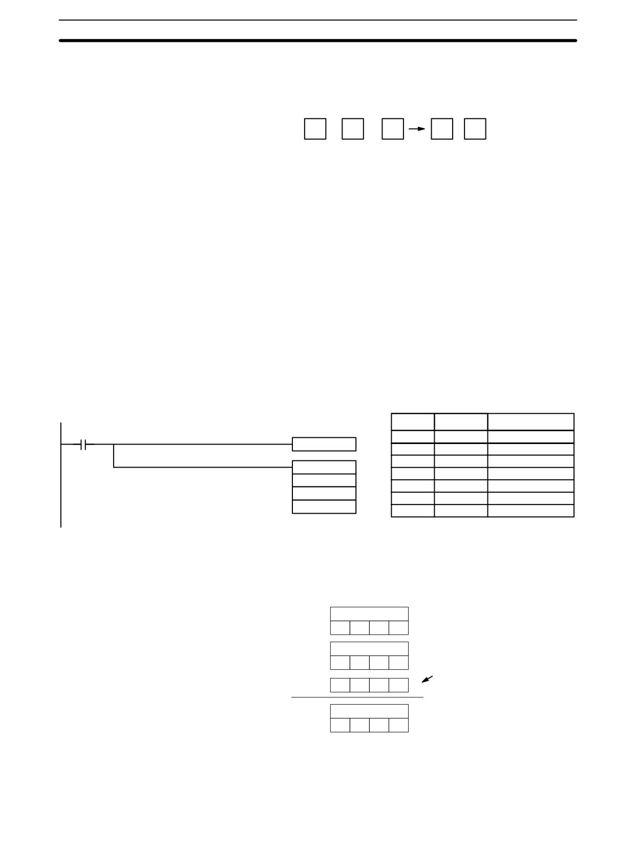
Binary Calculation Instructions
Section
7-22
When the execution condition is OFF, SBB(51) is not executed. When the
Description
execution condition is ON, SBB(51) subtracts the contents of Su and CY from Mi
and places the result in R. If the result is negative, CY is set and the 2’s comple-
ment of the actual result is placed in R.
Mi
-
Su
-
CY
CY
R
SBB(51) can also be used to subtract signed binary data. With the CPM1A,
CPM2A, CPM2C, and SRM1(-V2), the underflow and overflow flags (SR 25404
and SR 25405) indicate whether the result has exceeded the lower or upper lim-
its of the 16-bit signed binary data range.
Flags
ER:
Indirectly addressed DM word is non-existent. (Content of *DM word is
not BCD, or the DM area boundary has been exceeded.)
CY:
ON when the result is negative, i.e., when Mi is less than Su plus CY.
EQ:
ON when the result is 0.
OF:
ON when the result exceeds +32,767 (7FFF).
UF:
ON when the result is below -32,768 (8000).
Example
The following example shows a four-digit subtraction. When IR 00001 is ON, the
content of LR 00 and CY are subtracted from the content of IR 002 and the result
is written to HR 01.
CY is turned ON if the result is negative. If normal data is being used, a negative
result (signed binary) must be converted to normal data using NEG(--). Refer to
7-20-12 2’s COMPLEMENT - NEG(--) for details.
Address
Instruction
Operands
00001
00000
LD
00001
CLC(41)
00001
OUT
TR
1
00002
CLC(41)
SBB(51)
00003
SBB(51)
200
200
LR00
LR
00
HR 01
HR
01
In the case below, the content of LR 00 (#7A03) and CY are subtracted from
IR 002 (#F8C5). Since the result is positive, CY is 0.
If the result had been negative, CY would have been set to 1. For normal (un-
signed) data, the result would have to be converted to its 2’s complement.
Mi: IR 002
F
8
C
5
Su: LR 00
–
CY = 0
7
A
0
3
(from CLC(41))
-
0
0
0
0
R: HR 01
7
E
C
2
Note For signed binary calculations, the status of the UF and OF flags indicate wheth-
er the result has exceeded the signed binary data range (-32,768 (8000) to
+32,767 (7FFF)).
465
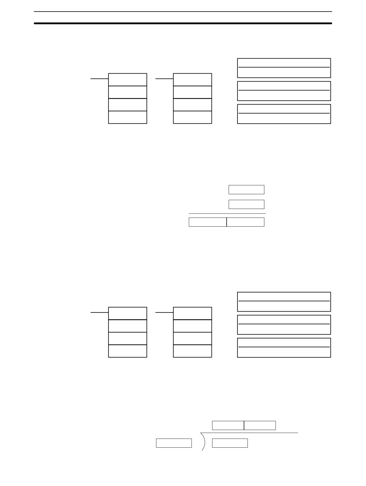
Binary Calculation Instructions
Section
7-22
7-22-3 BINARY MULTIPLY - MLB(52)
Operand Data Areas
Ladder Symbols
Md: Multiplicand word (binary)
IR, SR, AR, DM, HR, TC, LR, #
MLB(52)
@MLB(52)
Mr: Multiplier word (binary)
Md
Md
IR, SR, AR, DM, HR, TC, LR, #
Mr
Mr
R: First result word
R
R
IR, SR, AR, DM, HR LR
Limitations
DM 6144 to DM 6655 cannot be used for R.
MLB(52) cannot be used to multiply signed binary data.
Description
When the execution condition is OFF, MLB(52) is not executed. When the
execution condition is ON, MLB(52) multiplies the content of Md by the contents
of Mr, places the rightmost four digits of the result in R, and places the leftmost
four digits in R+1.
Md
X
Mr
R +1
R
Flags
ER:
Indirectly addressed DM word is non-existent. (Content of *DM word is
not BCD, or the DM area boundary has been exceeded.)
EQ:
ON when the result is 0.
7-22-4 BINARY DIVIDE - DVB(53)
Operand Data Areas
Ladder Symbols
Dd: Dividend word (binary)
IR, SR, AR, DM, HR, TC, LR, #
DVB(53)
@DVB(53)
Dr: Divisor word (binary)
Dd
Dd
IR, SR, AR, DM, HR, TC, LR, #
Dr
Dr
R: First result word
R
R
IR, SR, AR, DM, HR LR
Limitations
DM 6144 to DM 6655 cannot be used for R.
DVB(53) cannot be used to divide signed binary data.
Description
When the execution condition is OFF, DVB(53) is not executed. When the
execution condition is ON, DVB(53) divides the content of Dd by the content of
Dr and the result is placed in R and R+1: the quotient in R, the remainder in R+1.
Quotient
Remainder
R
R + 1
Dr
Dd
466
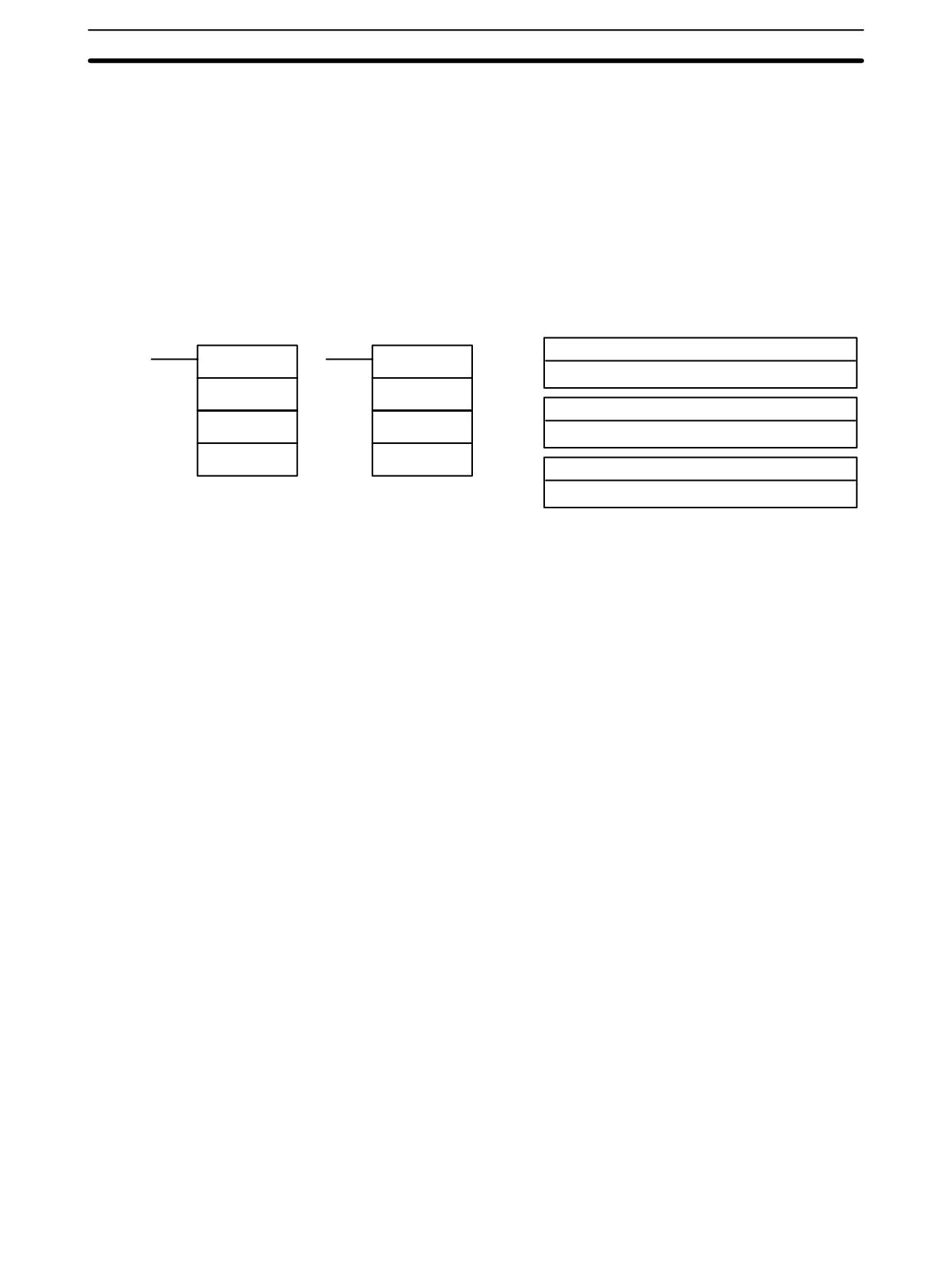
Special Math Instructions
Section
7-23
Flags
ER:
Dr contains 0.
Indirectly addressed DM word is non-existent. (Content of *DM word is
not BCD, or the DM area boundary has been exceeded.)
EQ:
ON when the result is 0.
7-23 Special Math Instructions
7-23-1
DATA SEARCH - SRCH(--)
Ladder Symbols
Operand Data Areas
N: Number of words
SRCH(--)
@SRCH(--)
IR, SR, AR, DM, HR, TC, LR, #
N
N
R1: First word in range
R1
R1
IR, SR, AR, DM, HR, TC, LR
C
C
C: Comparison data, result word
IR, SR, AR, DM, HR, LR
Limitations
This instruction is available in the CPM2A/CPM2C only.
N must be BCD between 0001 to 9999.
R1 and R1+N-1 must be in the same data area.
DM 6144 to DM 6655 cannot be used for C.
Description
When the execution condition is OFF, SRCH(--) is not executed. When the
execution condition is ON, SRCH(--) searches the range of memory from R1 to
R1+N-1 for addresses that contain the comparison data in C. If one or more ad-
dresses contain the comparison data, the EQ Flag (SR 25506) is turned ON and
the lowest address containing the comparison data is identified in C+1. The ad-
dress is identified differently for the DM area:
1, 2, 3...
1. For an address in the DM area, the word address is written to C+1. For ex-
ample, if the lowest address containing the comparison data is DM 0114,
then #0114 is written in C+1.
2. For an address in another data area, the number of addresses from the be-
ginning of the search is written to C+1. For example, if the lowest address
containing the comparison data is IR 114 and the first word in the search
range is IR 014, then #0100 is written in C+1.
If none of addresses in the range contain the comparison data, the EQ Flag
(SR 25506) is turned OFF and C+1 is left unchanged.
Flags
ER:
Indirectly addressed DM word is non-existent. (Content of *DM word is
not BCD, or the DM area boundary has been exceeded.)
N is not BCD between 0001 and 9999.
R1 and R1+N-1 are not in the same data area.
EQ:
ON when the comparison data has been matched in the search range.
Example
In the following example, the 10 word range from IR 200 to IR 209 is searched
for addresses that contain the same data as DM 0100 (89AB). Since IR 204 con-
467
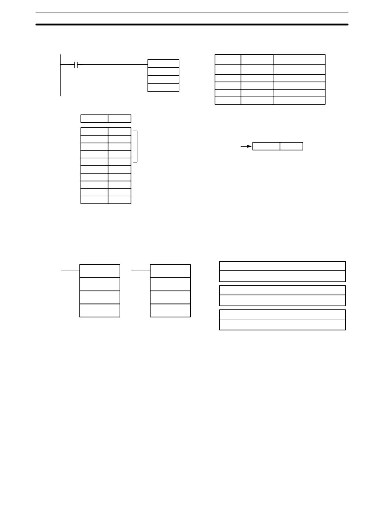
Special Math Instructions
Section
7-23
tains the same data, the EQ Flag (SR 25506) is turned ON and #0004 is written
to DM 0101.
00000
Address
Instruction
Operands
@SRCH(--)
#0010
00000
LD
00000
200
00001
@SRCH(--)
#
0010
DM 0100
0200
DM
0100
DM 0100
89AB
IR 200
1234
IR 201
5678
IR 202
ABCD
Offset: 0004
Offset of first word con-
DM 0101
0004
taining the search data
IR 203
EF13
IR 204
89AB
← Search data found
IR 205
8860
IR 206
90CD
IR 207
00FF
IR 208
89AB
← Search data found
IR 209
810C
Note The matching search data in IR 208 is ignored because the search data was
found in an earlier word in the range.
7-23-2
FIND MAXIMUM - MAX(--)
Ladder Symbols
Operand Data Areas
C: Control data
MAX(--)
@MAX(--)
IR, SR, AR, DM, HR, TC, LR, #
C
C
R1: First word in range
R1
R1
IR, SR, AR, DM, HR, TC, LR
D
D
D: Destination word
IR, SR, AR, DM, HR, LR
Limitations
This instruction is available in the CPM2A/CPM2C only.
N must be BCD between 0001 to 9999.
R1 and R1+N-1 must be in the same data area.
DM 6144 to DM 6655 cannot be used for D.
Description
When the execution condition is OFF, MAX(--) is not executed. When the
execution condition is ON, MAX(--) searches the range of memory from R1 to
R1+N-1 for the address that contains the maximum value and outputs the maxi-
mum value to the destination word (D).
The address is identified differently for the DM area:
1, 2, 3...
1. For an address in the DM area, the word address is written to C+1. For ex-
ample, if the address containing the maximum value is DM 0114, then #0114
is written in D+1.
2. For an address in another data area, the number of addresses from the be-
ginning of the search is written to D+1. For example, if the address contain-
ing the maximum value is IR 114 and the first word in the search range is
IR 014, then #0100 is written in D+1.
468
Special Math Instructions
Section 7-23
If bit 14 of C is ON and more than one address contains the same maximum val-
ue, the position of the lowest of the addresses will be output to D+1. The position
will be output as the DM address for the DM area, but as an absolute position
relative to the first word in the range for all other areas.
The number of words within the range (N) is contained in the 3 rightmost digits of
C, which must be BCD between 001 and 999.
When bit 15 of C is OFF, data within the range is treated as unsigned binary and
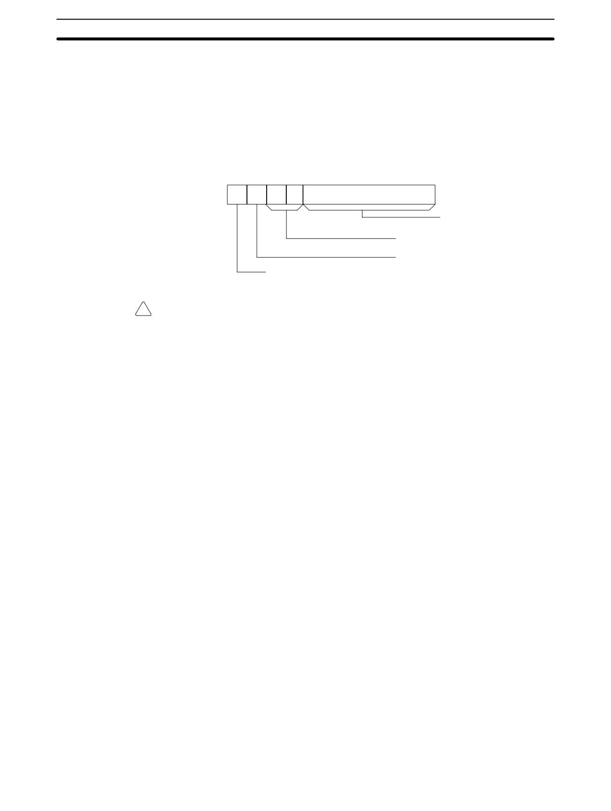
when it is ON the data is treated as signed binary.
15
14
13
12
11
00
C:
Number of words
in range (N: 001 to 999 BCD)
Not used - set to zero.
Output address to D+1?
1 (ON): Yes.
Not used - set to zero.
0 (OFF): No.
!
Caution If bit 14 of C is ON, values above #8000 are treated as negative numbers, so the
results will differ depending on the specified data type. Be sure that the correct
data type is specified.
Flags
ER:
Indirectly addressed DM word is non-existent. (Content of *DM word is
not BCD, or the DM area boundary has been exceeded.)
R1 and R1+N-1 are not in the same data area.
EQ:
ON when the maximum value is #0000.
Example
When IR 00000 is ON, the control data in DM 0000 (4010) will cause a search for
the maximum value in the 10 words starting at IR 200. The largest unsigned val-
469
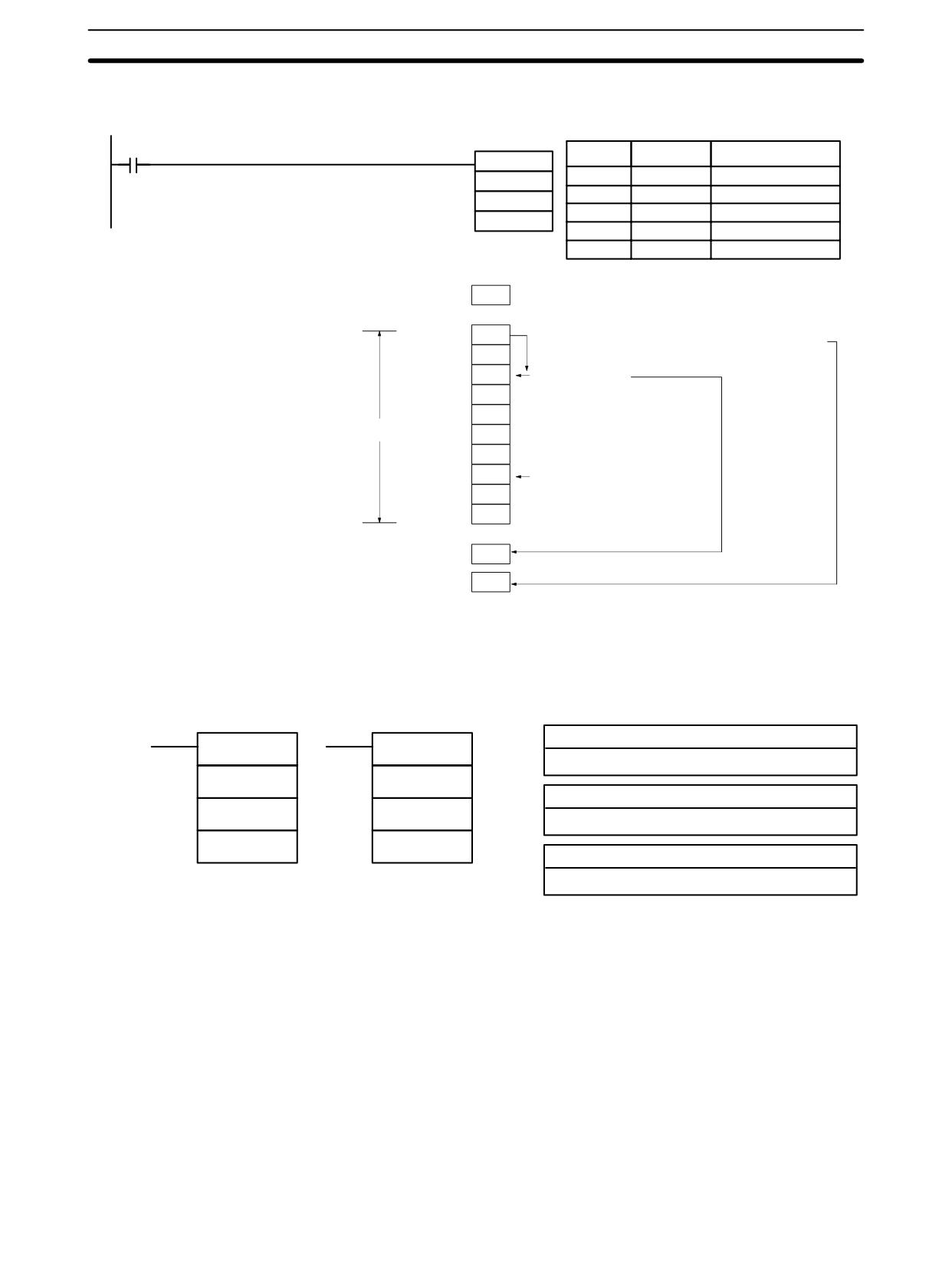
Special Math Instructions
Section
7-23
ue will be stored in DM 0500. The offset from the beginning of the search of the
word containing the maximum value will be stored in DM 0501.
00000
Address
Instruction
Operands
MAX(--)
00000
LD
00000
DM 0000
00001
MAX(--)
200
DM
0000
DM 0500
200
DM
0500
DM 0000
4010
IR 200
3F2A
Offset of word containing maximum value: 2 words
IR 201
51C3
IR 202
E02A
Maximum value
IR 203
7C9F
IR 204
2A20
10 words
IR 205
A827
IR 206
2A20
IR 207
E02A
Maximum value
IR 208
C755
IR 209
94DC
DM 0500
E02A
DM 0501
0002
If there are two words containing
the maximum value, the one found
first will be stored in DM 0501.
7-23-3
FIND MINIMUM - MIN(--)
Ladder Symbols
Operand Data Areas
C: Control data
MIN(--)
@MIN(--)
IR, SR, AR, DM, HR, TC, LR, #
C
C
R1: First word in range
R1
R1
IR, SR, AR, DM, HR, TC, LR
D
D
D: Destination word
IR, SR, AR, DM, HR, LR
Limitations
This instruction is available in the CPM2A/CPM2C only.
N must be BCD between 0001 to 9999.
R1 and R1+N-1 must be in the same data area.
DM 6144 to DM 6655 cannot be used for D.
Description
When the execution condition is OFF, MIN(--) is not executed. When the execu-
tion condition is ON, MIN(--) searches the range of memory from R1 to R1+N-1
for the address that contains the minimum value and outputs the minimum value
to the destination word (D).
The address is identified differently for the DM area:
1, 2, 3...
1. For an address in the DM area, the word address is written to C+1. For ex-
ample, if the address containing the minimum value is DM 0114, then #0114
is written in D+1.
470
Special Math Instructions
Section 7-23
2. For an address in another data area, the number of addresses from the be-
ginning of the search is written to D+1. For example, if the address contain-
ing the minimum value is IR 114 and the first word in the search range is
IR 014, then #0100 is written in D+1.
If bit 14 of C is ON and more than one address contains the same minimum val-
ue, the position of the lowest of the addresses will be output to D+1. The position
will be output as the DM address for the DM area, but as an absolute position
relative to the first word in the range for all other areas.
The number of words within the range (N) is contained in the 3 rightmost digits of
C, which must be BCD between 001 and 999.
When bit 15 of C is OFF, data within the range is treated as unsigned binary and
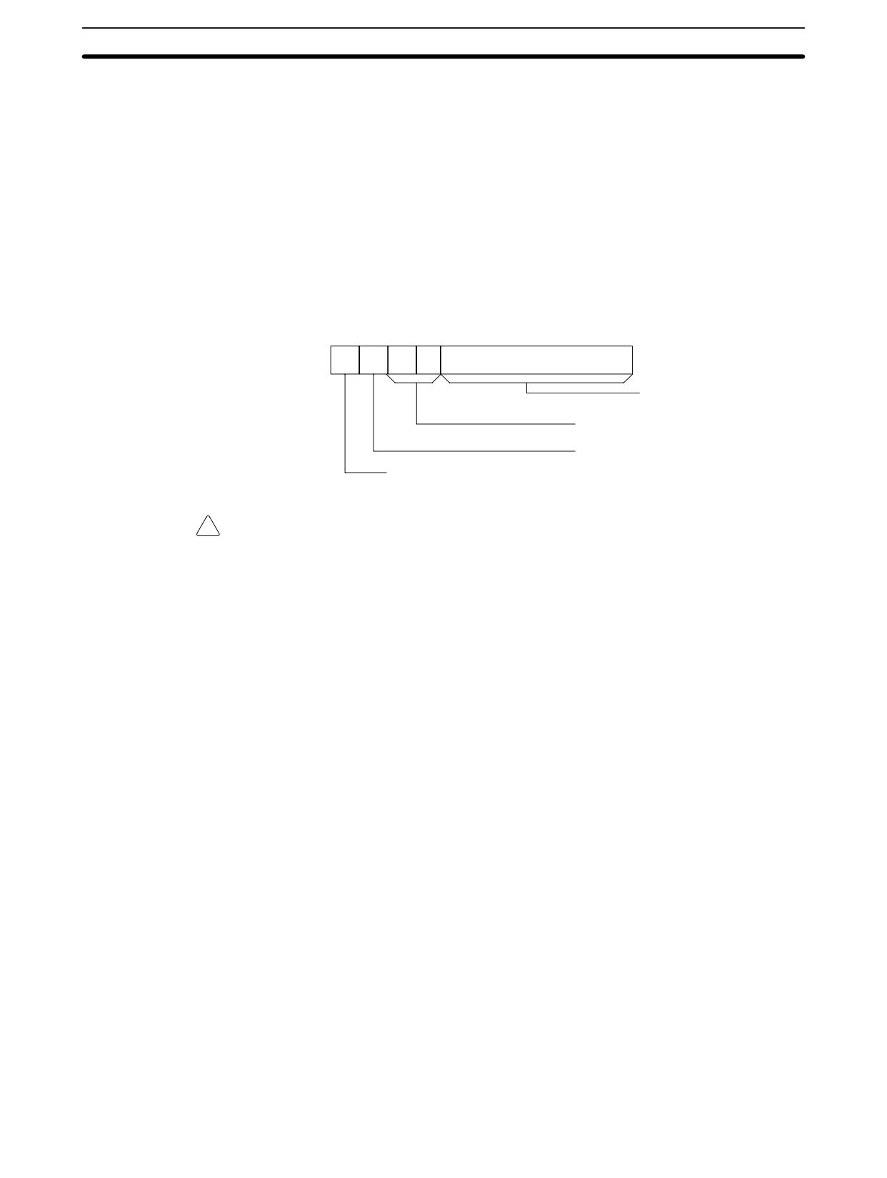
when it is ON the data is treated as signed binary.
15
14
13
12
11
00
C:
Number of words
in range (N: 001 to 999 BCD)
Not used - set to zero.
Output address to D+1?
1 (ON): Yes.
Not used - set to zero.
0 (OFF): No.
!
Caution If bit 14 of C is ON, values above #8000 are treated as negative numbers, so the
results will differ depending on the specified data type. Be sure that the correct
data type is specified.
Flags
ER:
Indirectly addressed DM word is non-existent. (Content of *DM word is
not BCD, or the DM area boundary has been exceeded.)
R1 and R1+N-1 are not in the same data area.
EQ:
ON when the minimum value is #0000.
Example
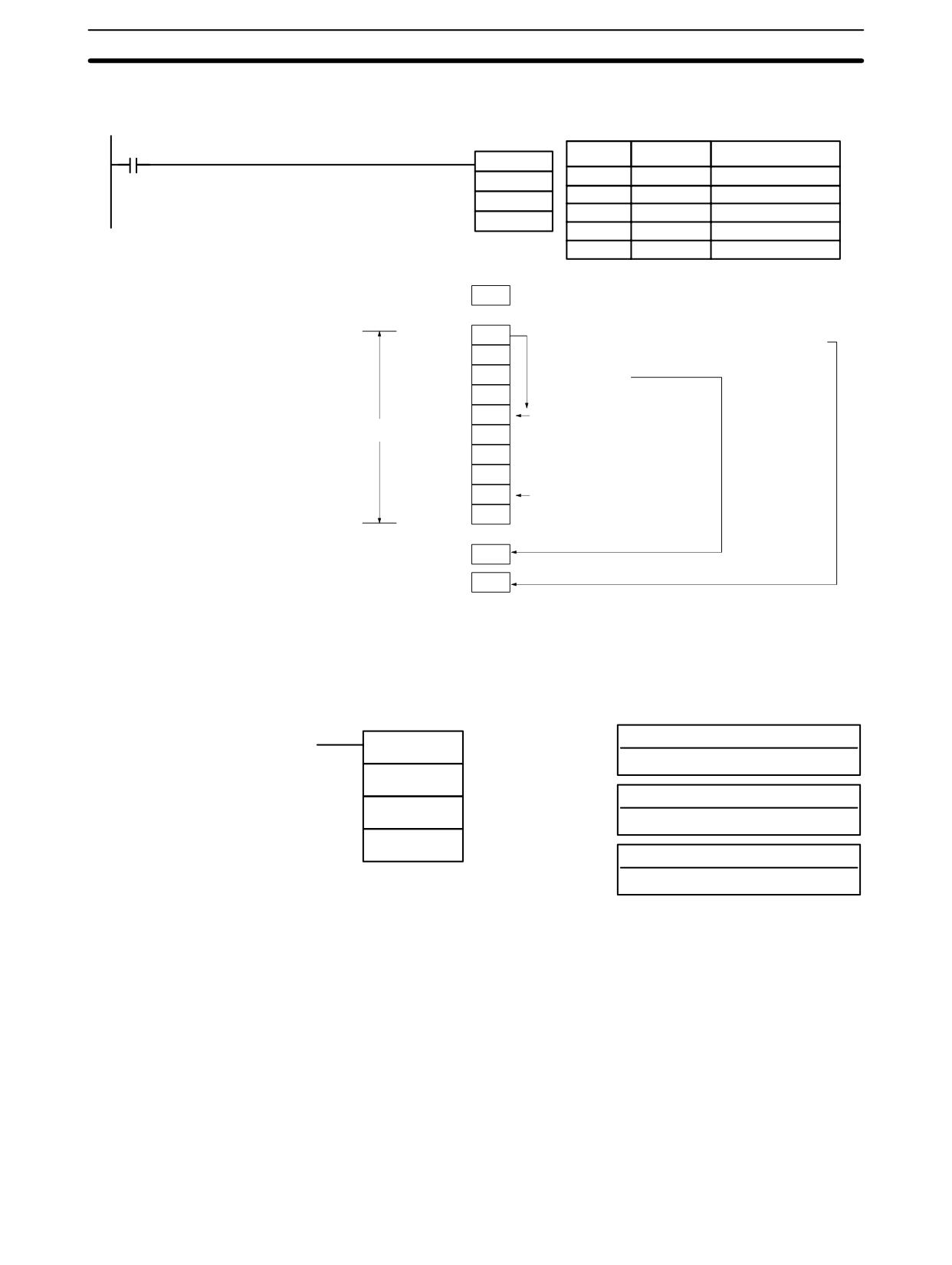
When IR 00000 is ON, the control data in DM 0300 (4010) will cause a search for
the maximum value in the 10 words starting at DM 0000. The smallest unsigned
471
Special Math Instructions
Section
7-23
value will be stored in DM 0500. The address of the word containing the mini-
mum value (0014) will be stored in DM 0501.
00000
Address
Instruction
Operands
MIN(--)
00000
LD
00000
DM 0300
00001
MIN(--)
DM 0000
DM
0300
DM 0500
DM
0000
DM
0500
DM 0300
4010
DM0010
3F2A
Address of word containing maximum value: 0014
DM0011
51C3
DM0012
E02A
DM0013
7C9F
DM0014
2A20
Minimum value
10 words
DM0015
A827
DM0016
33BF
DM0017
E02A
DM0018
2A20
Minimum value
DM0019
94DC
DM 0500
2A20
DM 0501
0014
If there are two words containing
the minimum value, the one found
first will be stored in DM 0501.
7-23-4
AVERAGE VALUE - AVG(--)
Ladder Symbols
Operand Data Areas
S: Source word
AVG(--)
IR, SR, AR, DM, HR, TC, LR
S
N: Number of cycles
N
IR, SR, AR, DM, HR, TC, LR, #
D
D: First destination word
IR, SR, AR, DM, HR, LR
Limitations
This instruction is available in the CPM2A/CPM2C only.
S must be hexadecimal.
N must be BCD from #0001 to #0064.
D and D+N+1 must be in the same data area.
DM 6144 to DM 6655 cannot be used for S, N, or D to D+N+1.
Description
AVG(--) is used to calculate the average value of S over N cycles.
When the execution condition is OFF, AVG(--) is not executed.
Each time that AVG(--) is executed, the content of S is stored in words D+2 to
D+N+1. On the first execution, AVG(--) writes the content of S to D+2; on the
second execution it writes the content of S to D+3, etc. On the Nth execution,
AVG(--) writes the content of S is stored in D+N+1, AVG(--) calculates the av-
erage value of the values stored in D+2 to D+N+1, and writes the average to D.
472
Special Math Instructions
Section
7-23
The following diagram shows the function of words D to D+N+1.
D
Average value (after N or more executions)
D+1
Used by the system.
D+2
Content of S from the 1st execution of AVG(--)
D+3
Content of S from the 2nd execution of AVG(--)
D+N+1
Content of S from the Nth execution of AVG(--)
Precautions
The average value is calculated in binary. Be sure that the content of S is in
binary.
N must be BCD from #0001 to #0064. If the content of N ≥ #0065, AVG(--) will
operate with N=64.
The average value will be rounded off to the nearest integer value. (0.5 is
rounded up to 1.)
Set the contents of D+1 to #0000 to execute AVG(--) from the first scan.
Flags
ER:
Indirectly addressed DM word is non-existent. (Content of *DM word is
not BCD, or the DM area boundary has been exceeded.)
One or more operands have been set incorrectly.
D and D+N+1 are not in the same data area.
Example
In the following example, the content of IR 200 is set to #0000 and then increm-
ented by 1 each cycle. For the first two cycles, AVG(--) moves the content of
IR 200 to DM 1002 and DM 1003. On the third and later cycles AVG(--) calcu-
lates the average value of the contents of DM 1002 to DM 1004 and writes that
average value to DM 1000.
00001
@MOV(21)
Address
Instruction
Operands
#0000
00000
LD
00001
200
00001
@MOV(21)
#
0000
AVG(--)
200
200
00002
AVG(--)
#0003
200
DM 1000
#
0003
DM
1000
CLC(41)
00003
CLC(41)
00004
ADB(50)
200
ADB(50)
#
0001
200
200
#0001
200
1st cycle
2nd cycle
3rd cycle
4th cycle
IR 200
0000
0001
0002
0003
1st cycle
2nd cycle
3rd cycle
4th cycle
DM 1000
0000
0001
0001
0002
Average
DM 1001
Used by the system.
DM 1002
0000
0000
0000
0003
Previous
DM 1003
---
0001
0001
0001
values of
DM 1004
---
---
0002
0002
IR 200
473
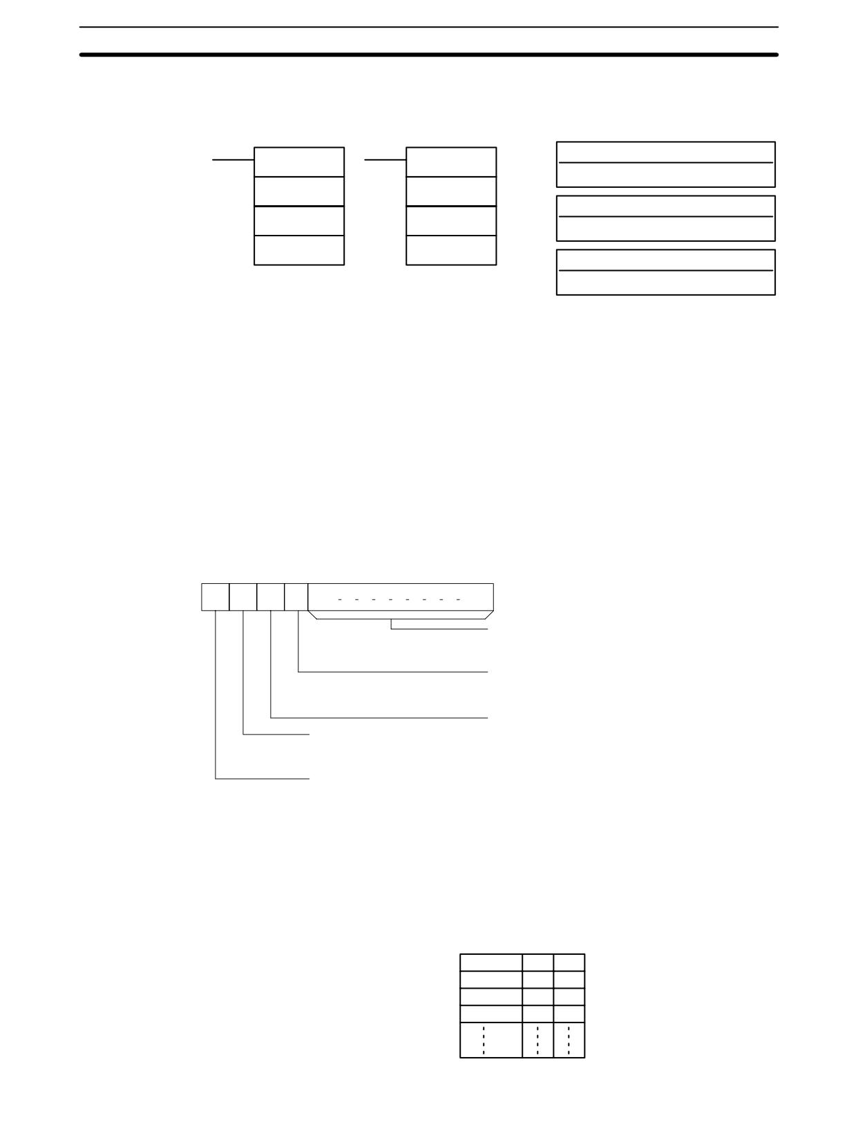
Special Math Instructions
Section
7-23
7-23-5
SUM - SUM(--)
Ladder Symbols
Operand Data Areas
C: Control data
SUM(--)
@SUM(--)
IR, SR, AR, DM, HR, LR, #
C
C
R1: First word in range
R1
R1
IR, SR, AR, DM, HR, TC, LR
D
D
D: First destination word
IR, SR, AR, DM, HR, LR
Limitations
This instruction is available in the CPM2A/CPM2C only.
The 3 rightmost digits of C must be BCD between 001 and 999.
DM 6144 to DM 6655 cannot be used for D.
If bit 14 of C is OFF (setting for BCD data), all data within the range R1 to R1+N-1
must be BCD.
Description
When the execution condition is OFF, SUM(--) is not executed. When the
execution condition is ON, SUM(--) adds either the contents of words R1 to
R1+N-1 or the bytes in words R1 to R1+N/2-1 and outputs that value to the des-
tination words (D and D+1). The data can be summed as binary or BCD and will
be output in the same form. Binary data can be either signed or unsigned.
The function of bits in C are shown in the following diagram and explained in
more detail below.
15
14
13
12
11
00
C:
Number of items in range (N, BCD)
Number of words or number of bytes
001 to 999
First byte (when bit 13 is ON)
1 (ON): Rightmost
0 (OFF): Leftmost
Addition units
1 (ON): Bytes
Data type
0 (OFF): Words
1 (ON): Binary
0 (OFF): BCD
Not used - set to zero.
Number of Items in Range
The number of items within the range (N) is contained in the 3 rightmost digits of
C, which must be BCD between 001 and 999. This number will indicate the num-
ber of words or the number of bytes depending the items being summed.
Addition Units
Words will be added if bit 13 is OFF and bytes will be added if bit 13 is ON.
If bytes are specified, the range can begin with the leftmost or rightmost byte of
R1. The leftmost byte of R1 will not be added if bit 12 is ON.
MSB LSB
R1
1
2
R1+1
3
4
R1+2
5
6
R1+3
7
8
474
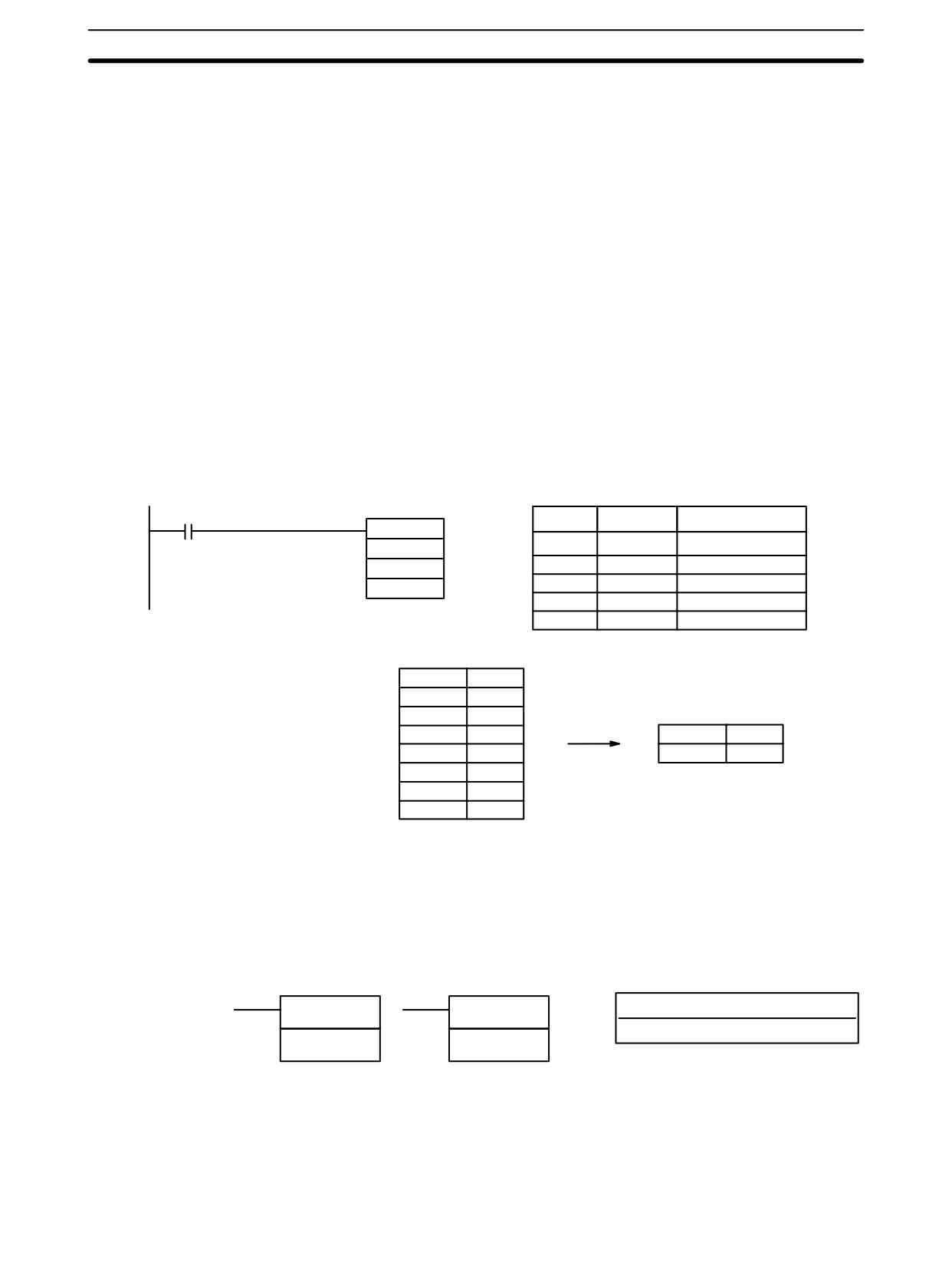
Logic Instructions
Section
7-24
The bytes will be added in this order when bit 12 is OFF: 1+2+3+4
The bytes will be added in this order when bit 12 is ON: 2+3+4
Data Type
Data within the range is treated as unsigned binary when bit 14 of C is ON and bit
15 is OFF, and it is treated as signed binary when both bits 14 and 15 are ON.
Data within the range is treated as BCD when bit 14 of C is OFF, regardless of the
status of bit 15.
Flags
ER:
Indirectly addressed DM word is non-existent. (Content of *DM word is
not BCD, or the DM area boundary has been exceeded.)
R1 and R1+N-1 are not in the same data area.
The number of items in C is not BCD between 001 and 999.
The data being summed in not BCD when BCD was designated.
EQ:
ON when the result is zero.
Example
In the following example, the BCD contents of the 8 words from DM 0000 to
DM 0007 are added when IR 00001 is ON and the result is written to DM 0010
and DM 0011.
00001
Address
Instruction
Operands
@SUM(--)
#0008
00000
LD
00001
DM 0000
00001
@SUM(--)
#
0008
DM 0010
DM
0000
DM
0010
DM 0000
0001
DM 0001
0002
DM 0002
0003
DM 0003
0004
DM 0010
0036
DM 0004
0005
DM 0011
0000
DM 0005
0006
DM 0006
0007
DM 0007
0008
7-24 Logic Instructions
7-24-1 COMPLEMENT - COM(29)
Ladder Symbols
Operand Data Areas
Wd: Complement word
COM(29)
@COM(29)
IR, SR, AR, DM, HR, LR
Wd
Wd
Limitations
DM 6144 to DM 6655 cannot be used for Wd.
Description
When the execution condition is OFF, COM(29) is not executed. When the
execution condition is ON, COM(29) clears all ON bits and sets all OFF bits in
Wd.
475
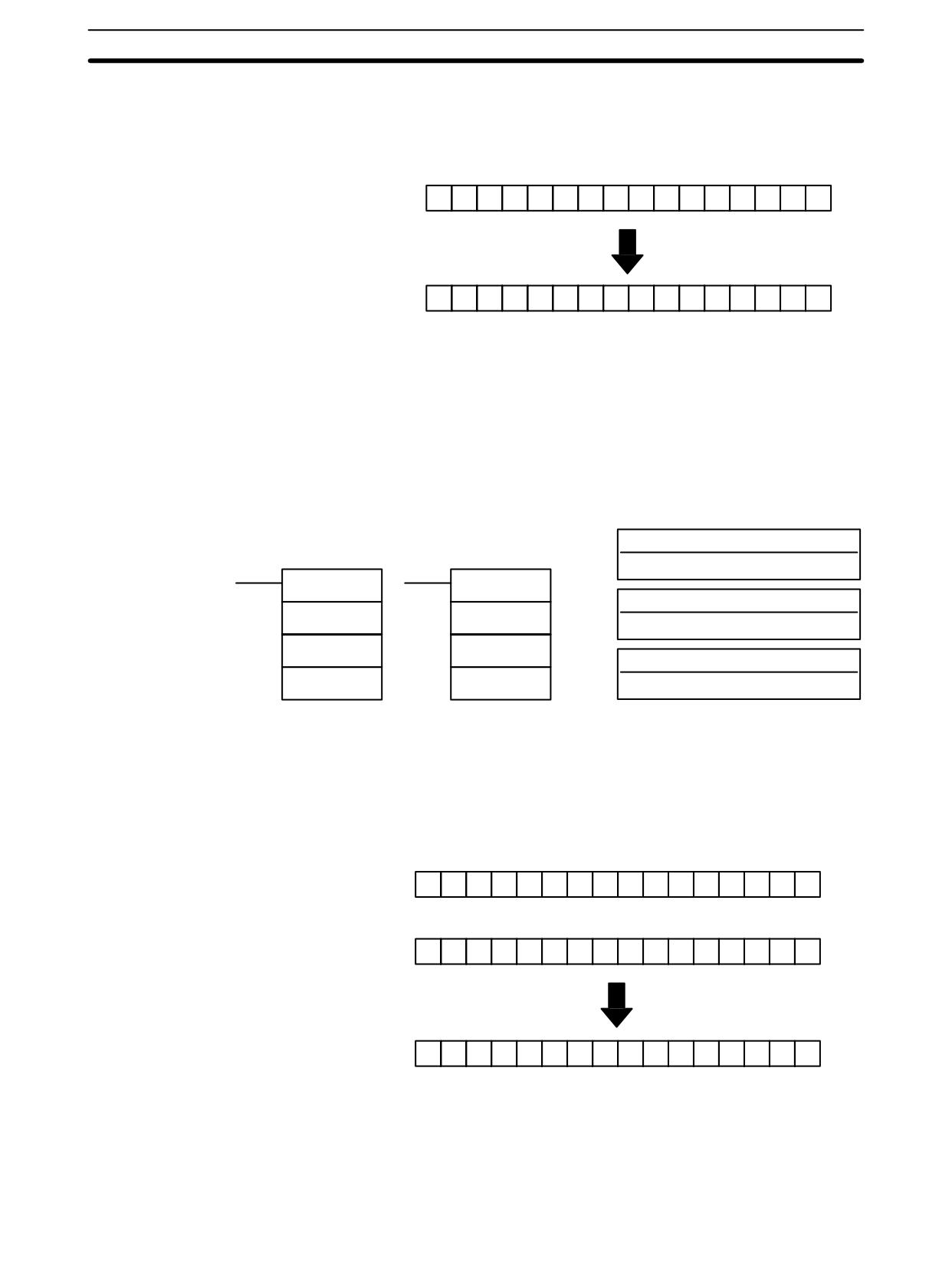
Logic Instructions
Section
7-24
Precautions
The complement of Wd will be calculated every cycle if the undifferentiated form
of COM(29) is used. Use the differentiated form (@COM(29)) or combine
COM(29) with DIFU(13) or DIFD(14) to calculate the complement just once.
Example
15
00
Original
1
0
0
1
1
0
0
1
1
0
0
1
1
0
0
1
15
00
Complement
0
1
1
0
0
1
1
0
0
1
1
0
0
1
1
0
Flags
ER:
Indirectly addressed DM word is non-existent. (Content of *DM word is
not BCD, or the DM area boundary has been exceeded.)
EQ:
ON when the result is 0.
7-24-2 LOGICAL AND - ANDW(34)
Operand Data Areas
Ladder Symbols
I1: Input 1
IR, SR, AR, DM, HR, TC, LR, #
ANDW(34)
@ANDW(34)
I2: Input 2
I1
I1
IR, SR, AR, DM, HR, TC, LR, #
I2
I2
R: Result word
R
R
IR, SR, AR, DM, HR, LR
Limitations
DM 6144 to DM 6655 cannot be used for R.
Description
When the execution condition is OFF, ANDW(34) is not executed. When the
execution condition is ON, ANDW(34) logically AND’s the contents of I1 and I2
bit-by-bit and places the result in R.
Example
15
00
I1
1
0
0
1
1
0
0
1
1
0
0
1
1
0
0
1
15
00
0
1
0
1
0
1
0
1
0
1
0
1
0
1
0
1
I2
15
00
0
0
0
1
0
0
0
1
0
0
0
1
0
0
0
1
R
Flags
ER:
Indirectly addressed DM word is non-existent. (Content of *DM word is
not BCD, or the DM area boundary has been exceeded.)
EQ:
ON when the result is 0.
476
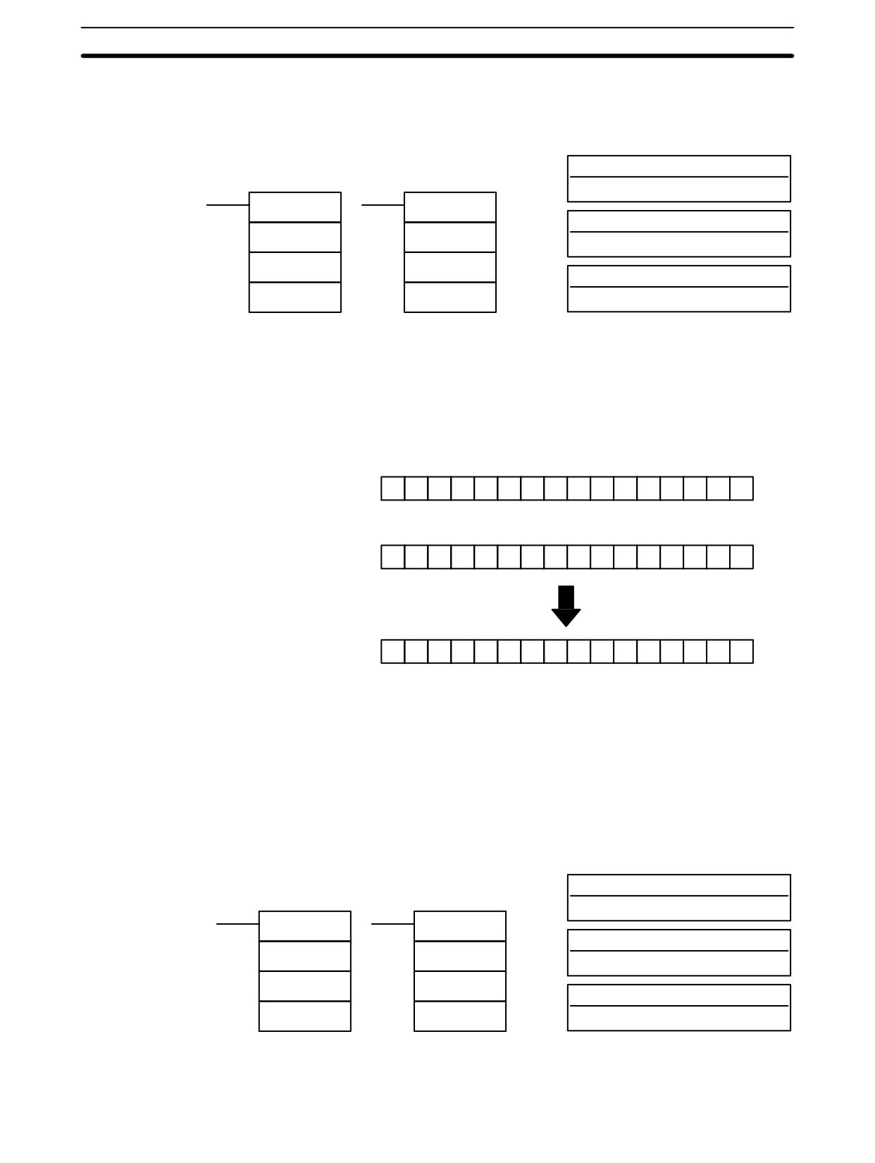
Logic Instructions
Section
7-24
7-24-3 LOGICAL OR - ORW(35)
Operand Data Areas
Ladder Symbols
I1: Input 1
IR, SR, AR, DM, HR, TC, LR, #
ORW(35)
@ORW(35)
I2: Input 2
I1
I1
IR, SR, AR, DM, HR, TC, LR, #
I2
I2
R: Result word
R
R
IR, SR, AR, DM, HR, LR
Limitations
DM 6144 to DM 6655 cannot be used for R.
Description
When the execution condition is OFF, ORW(35) is not executed. When the
execution condition is ON, ORW(35) logically OR’s the contents of I1 and I2 bit-
by-bit and places the result in R.
15
00
Example
I1
1
0
0
1
1
0
0
1
1
0
0
1
1
0
0
1
15
00
I2
0
1
0
1
0
1
0
1
0
1
0
1
0
1
0
1
15
00
R
1
1
0
1
1
1
0
1
1
1
0
1
1
1
0
1
Flags
ER:
Indirectly addressed DM word is non-existent. (Content of *DM word is
not BCD, or the DM area boundary has been exceeded.)
EQ:
ON when the result is 0.
7-24-4 EXCLUSIVE OR - XORW(36)
Operand Data Areas
Ladder Symbols
I1: Input 1
IR, SR, AR, DM, HR, TC, LR, #
XORW(36)
@XORW(36)
I2: Input 2
I1
I1
IR, SR, AR, DM, HR, TC, LR, #
I2
I2
R: Result word
R
R
IR, SR, AR, DM, HR, LR
Limitations
DM 6144 to DM 6655 cannot be used for R.
477
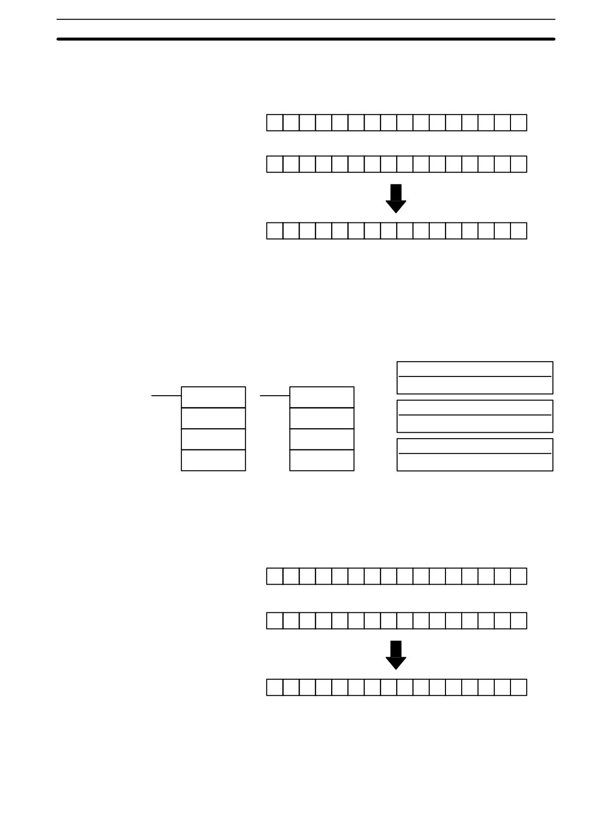
Logic Instructions
Section
7-24
When the execution condition is OFF, XORW(36) is not executed. When the
Description
execution condition is ON, XORW(36) exclusively OR’s the contents of I1 and I2
bit-by-bit and places the result in R.
Example
15
00
I1
1
0
0
1
1
0
0
1
1
0
0
1
1
0
0
1
15
00
I2
0
1
0
1
0
1
0
1
0
1
0
1
0
1
0
1
15
00
R
1
1
0
0
1
1
0
0
1
1
0
0
1
1
0
0
Flags
ER:
Indirectly addressed DM word is non-existent. (Content of *DM word is
not BCD, or the DM area boundary has been exceeded.)
EQ:
ON when the result is 0.
7-24-5 EXCLUSIVE NOR - XNRW(37)
Operand Data Areas
Ladder Symbols
I1: Input 1
IR, SR, AR, DM, HR, TC, LR, #
XNRW(37)
@XNRW(37)
I2: Input 2
I1
I1
IR, SR, AR, DM, HR, TC, LR, #
I2
I2
R: Result word
R
R
IR, SR, AR, DM, HR, LR
Limitations
DM 6144 to DM 6655 cannot be used for R.
Description
When the execution condition is OFF, XNRW(37) is not executed. When the
execution condition is ON, XNRW(37) exclusively NOR’s the contents of I1 and
I2 bit-by-bit and places the result in R.
15
00
I1
1
0
0
1
1
0
0
1
1
0
0
1
1
0
0
1
15
00
I2
0
1
0
1
0
1
0
1
0
1
0
1
0
1
0
1
15
00
R
0
0
1
1
0
0
1
1
0
0
1
1
0
0
1
1
Flags
ER:
Indirectly addressed DM word is non-existent. (Content of *DM word is
not BCD, or the DM area boundary has been exceeded.)
EQ:
ON when the result is 0.
478
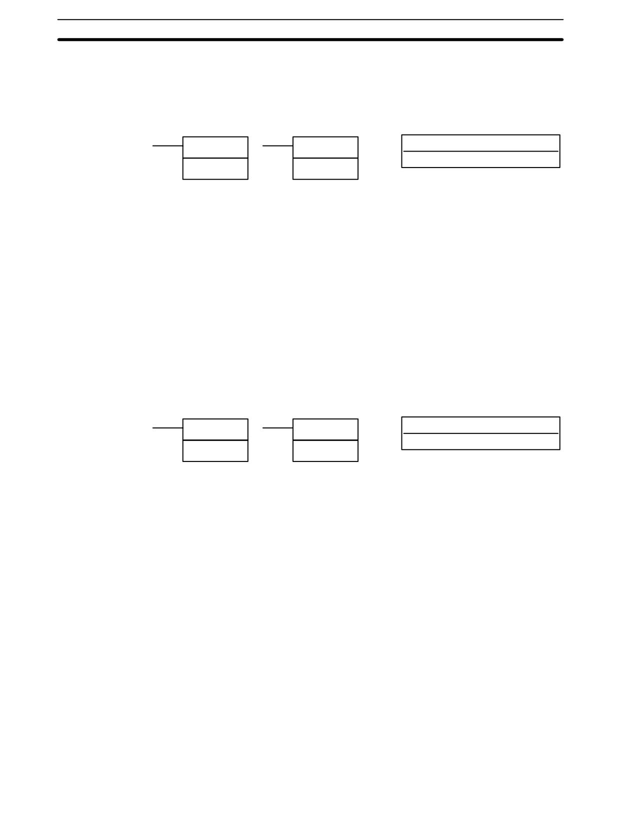
Increment/Decrement Instructions
Section
7-25
7-25 Increment/Decrement Instructions
7-25-1
BCD INCREMENT - INC(38)
Ladder Symbols
Operand Data Areas
Wd: Increment word (BCD)
INC(38)
@INC(38)
IR, SR, AR, DM, HR, LR
Wd
Wd
Limitations
DM 6144 to DM 6655 cannot be used for Wd.
Description
When the execution condition is OFF, INC(38) is not executed. When the execu-
tion condition is ON, INC(38) increments Wd, without affecting Carry (CY).
Precautions
The content of Wd will be incremented every cycle if the undifferentiated form of
INC(38) is used. Use the differentiated form (@INC(38)) or combine INC(38)
with DIFU(13) or DIFD(14) to increment Wd just once.
Flags
ER:
Wd is not BCD
Indirectly addressed DM word is non-existent. (Content of *DM word is
not BCD, or the DM area boundary has been exceeded.)
EQ:
ON when the incremented result is 0.
7-25-2
BCD DECREMENT - DEC(39)
Ladder Symbols
Operand Data Areas
Wd: Decrement word (BCD)
DEC(39)
@DEC(39)
IR, SR, AR, DM, HR, LR
Wd
Wd
Limitations
DM 6144 to DM 6655 cannot be used for Wd.
Description
When the execution condition is OFF, DEC(39) is not executed. When the
execution condition is ON, DEC(39) decrements Wd, without affecting CY.
DEC(39) works the same way as INC(38) except that it decrements the value
instead of incrementing it.
Precautions
The content of Wd will be decremented every cycle if the undifferentiated form of
DEC(39) is used. Use the differentiated form (@DEC(39)) or combine DEC(39)
with DIFU(13) or DIFD(14) to decrement Wd just once.
Flags
ER:
Wd is not BCD.
Indirectly addressed DM word is non-existent. (Content of *DM word is
not BCD, or the DM area boundary has been exceeded.)
EQ:
ON when the decremented result is 0.
479
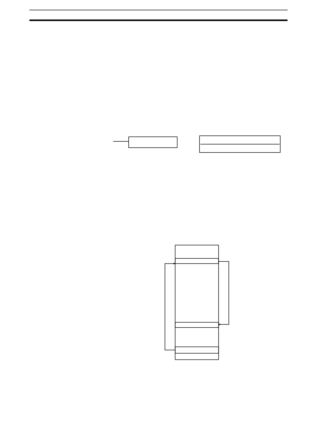
Subroutine Instructions
Section
7-26
7-26
Subroutine Instructions
Subroutines break large control tasks into smaller ones and enable you to reuse
a given set of instructions. When the main program calls a subroutine, control is
transferred to the subroutine and the subroutine instructions are executed. The
instructions within a subroutine are written in the same way as main program
code. When all the subroutine instructions have been executed, control returns
to the main program to the point just after the point from which the subroutine
was entered (unless otherwise specified in the subroutine).
7-26-1 SUBROUTINE ENTER - SBS(91)
Ladder Symbol
Definer Data Areas
N: Subroutine number
SBS(91) N
000 to 049
Limitations
The subroutine number must be between 000 and 049.
Description
A subroutine can be executed by placing SBS(91) in the main program at the
point where the subroutine is desired. The subroutine number used in SBS(91)
indicates the desired subroutine. When SBS(91) is executed (i.e., when the
execution condition for it is ON), the instructions between the SBN(92) with the
same subroutine number and the first RET(93) after it are executed before
execution returns to the instruction following the SBS(91) that made the call.
Main program
SBS(91)
000
Main program
SBN(92)
000
Subroutine
RET(93)
END(01)
SBS(91) may be used as many times as desired in the program, i.e., the same
subroutine may be called from different places in the program).
480
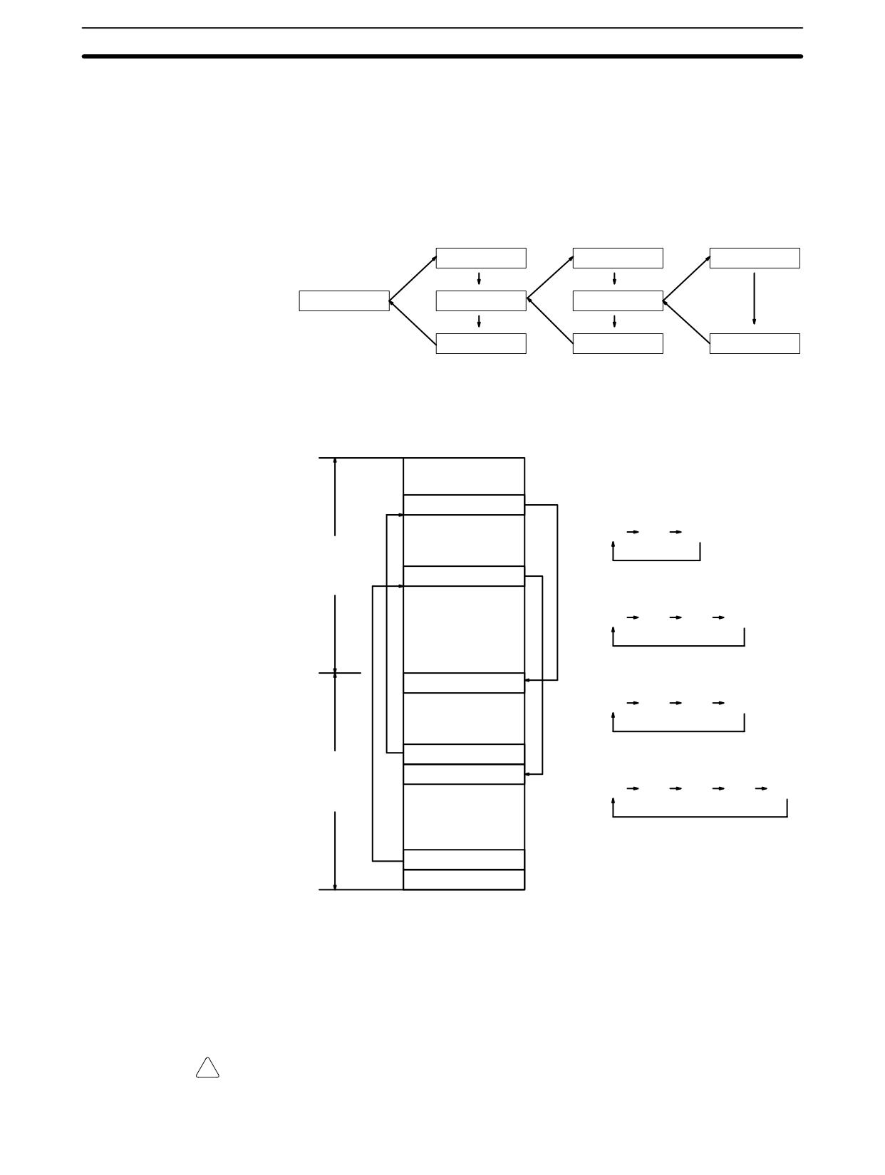
Subroutine Instructions
Section 7-26
SBS(91) may also be placed into a subroutine to shift program execution from
one subroutine to another, i.e., subroutines may be nested. When the second
subroutine has been completed (i.e., RET(93) has been reached), program
execution returns to the original subroutine which is then completed before re-
turning to the main program. Nesting is possible to up to sixteen levels. A sub-
routine cannot call itself (e.g., SBS(91) 000 cannot be programmed within the
subroutine defined with SBN(92) 000). The following diagram illustrates two lev-
els of nesting.
SBN(92) 010
SBN(92) 011
SBN(92) 012
SBS(91) 010
SBS(91) 011
SBS(91) 012
RET(93)
RET(93)
RET(93)
The following diagram illustrates program execution flow for various execution
conditions for two SBS(91).
A
SBS(91)
000
OFF execution conditions for
subroutines 000 and 001
A
B
C
B
Main
program
SBS(91)
001
ON execution condition for
subroutine 000 only
A
D
B
C
C
ON execution condition for
SBN(92)
000
subroutine 001 only
A
B
E
C
D
RET(93)
ON execution conditions for
SBN(92)
001
subroutines 000 and 001
Subroutines
A
D
B
E
C
E
RET(93)
END(01)
Flags
ER:
A subroutine does not exist for the specified subroutine number.
A subroutine has called itself.
An active subroutine has been called.
!
Caution SBS(91) will not be executed and the subroutine will not be called when ER is
ON.
481
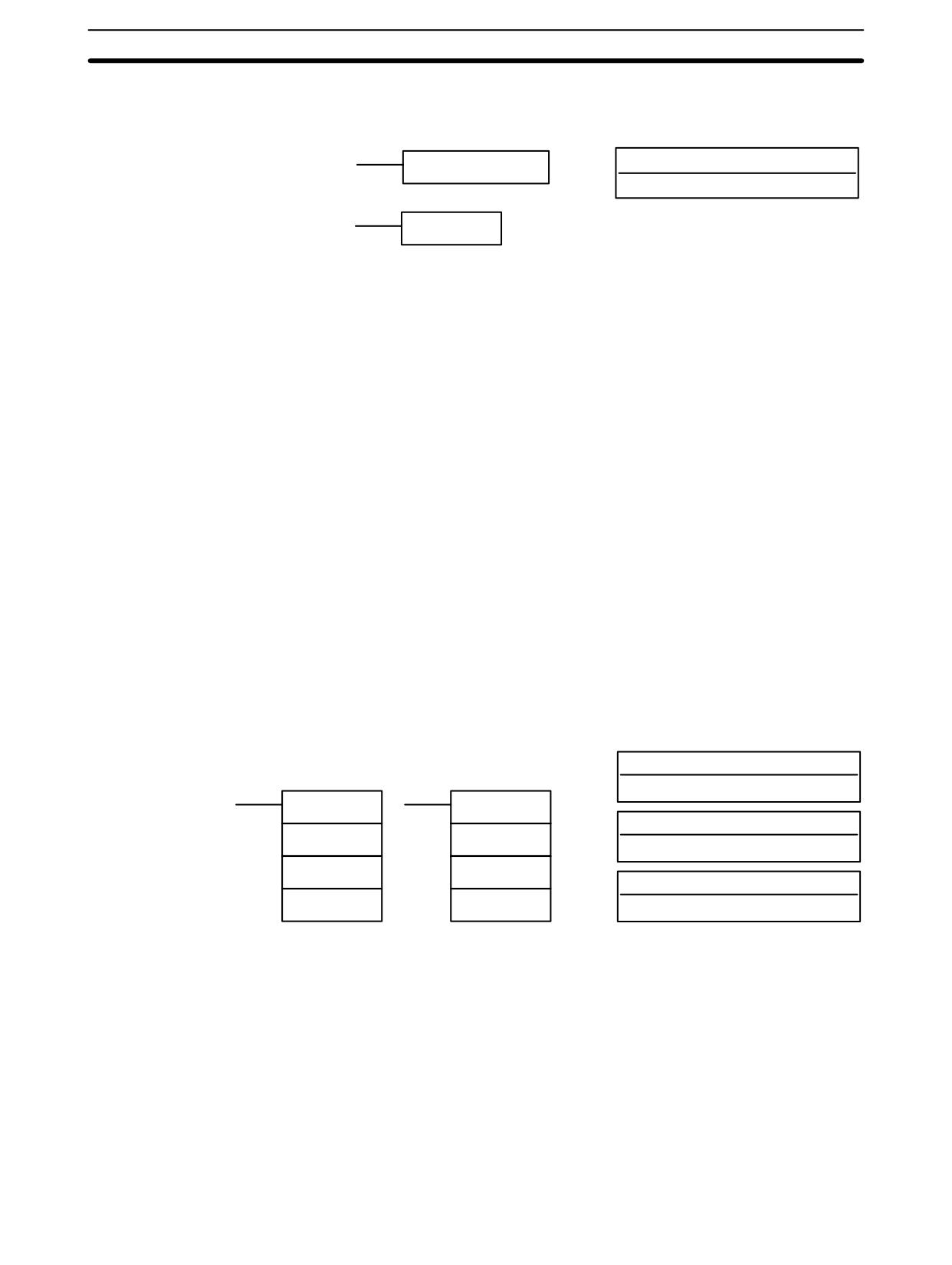
Subroutine Instructions
Section
7-26
7-26-2 SUBROUTINE DEFINE and RETURN - SBN(92)/RET(93)
Ladder Symbols
Definer Data Areas
N: Subroutine number
SBN(92) N
000 to 049
RET(93)
Limitations
The subroutine number must be between 000 and 049.
Each subroutine number can be used in SBN(92) once only.
Description
SBN(92) is used to mark the beginning of a subroutine program; RET(93) is
used to mark the end. Each subroutine is identified with a subroutine number, N,
that is programmed as a definer for SBN(92). This same subroutine number is
used in any SBS(91) that calls the subroutine (see 7-26-1 SUBROUTINE EN-
TER - SBS(91)). No subroutine number is required with RET(93).
All subroutines must be programmed at the end of the main program. When one
or more subroutines have been programmed, the main program will be
executed up to the first SBN(92) before returning to address 00000 for the next
cycle. Subroutines will not be executed unless called by SBS(91).
END(01) must be placed at the end of the last subroutine program, i.e., after the
last RET(93). It is not required at any other point in the program.
Precautions
If SBN(92) is mistakenly placed in the main program, it will inhibit program
execution past that point, i.e., program execution will return to the beginning
when SBN(92) is encountered.
If either DIFU(13) or DIFU(14) is placed within a subroutine, the operand bit will
not be turned OFF until the next time the subroutine is executed, i.e., the oper-
and bit may stay ON longer than one cycle.
Flags
There are no flags directly affected by these instructions.
7-26-3
MACRO - MCRO(99)
Operand Data Areas
Ladder Symbols
N: Subroutine number
000 to 127
MCRO(99)
@MCRO(99)
I1: First input word
N
N
IR, SR, AR, DM, HR, TC, LR
I1
I1
O1: First output word
O1
O1
IR, SR, AR, DM, HR, LR
The subroutine number must be between 000 and 049.
Limitations
If a DM address is used for O1, O1 through O1+3 must be read/write DM.
Description
The MACRO instruction allows a single subroutine to replace several subrou-
tines that have identical structure but different operands. There are 4 input
words (SR 232 to SR 235) and 4 output words (SR 236 to SR 239), allocated to
MCRO(99). These 8 words are used in the subroutine and take their contents
from I1 to I1+3 and O1 to O1+3 when the subroutine is executed.
When the execution condition is OFF, MCRO(99) is not executed. When the
execution condition is ON, MCRO(99) copies the contents of I1 to I1+3 to SR 232
to SR 235, and then calls and executes the subroutine specified in N. When the
subroutine is completed, the contents of SR 236 through SR 239 are then trans-
ferred back to O1 to O1+3 before MCRO(99) is completed.
482
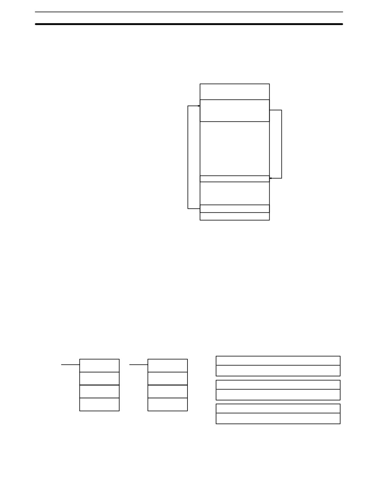
Pulse Output Instructions
Section
7-27
Note Refer to page 153 for more details on MCRO(99).
Example
In this example, the contents of DM 0010 through DM 0013 are copied to SR 232
through SR 235, and then subroutine 10 is called and executed. When the sub-
routine is completed, the contents of SR 236 through SR 239 are copied to out-
put words DM 0020 to DM 0023.
Main program
MCRO(99)
010
DM 0010
DM 0020
Main program
SBN(92)
010
Subroutine
RET(93)
END(01)
Flags
ER:
A subroutine does not exist for the specified subroutine number.
An operand has exceeded a data area boundary.
Indirectly addressed DM word is non-existent. (Content of *DM word is
not BCD, or the DM area boundary has been exceeded.)
A subroutine has called itself.
An active subroutine has been called.
7-27 Pulse Output Instructions
7-27-1
SET PULSES - PULS(65)
Ladder Symbols
Operand Data Areas
P: Port specifier
PULS(65)
@PULS(65)
000 or 010
P
P
C: Control data
C
C
000 or 001
N
N
N: Number of pulses
IR, SR, AR, DM, HR, LR
Limitations
This instruction is supported by the CPM1A and CPM2A/CPM2C PCs with
transistor outputs only.
N and N+1 must be in the same data area.
DM 6144 to DM 6655 cannot be used for N.
483
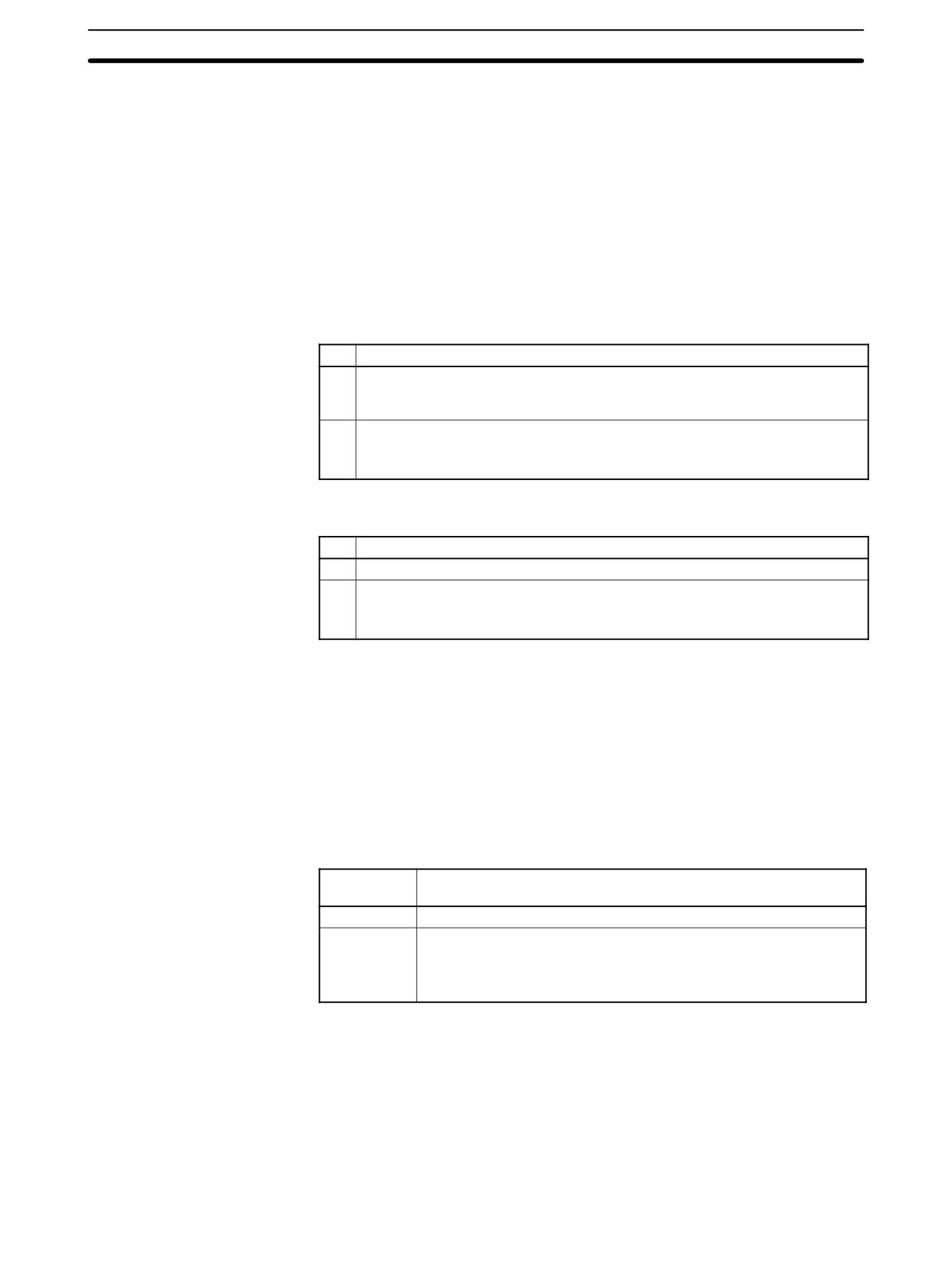
Pulse Output Instructions
Section
7-27
Description
PULS(65) is used to set the number of pulses for pulse outputs that are started
later in the program using SPED(64) or ACC(--). The number of pulses set with
PULS(65) are output in independent mode.
The number of pulses cannot be changed while pulses are being output. In gen-
eral, PULS(65) should be executed just once each time that the number of
pulses needs to be set; use the differentiated variation (@PULS(65)) or an input
condition that is ON for just one cycle.
Note Refer to 2-5 Pulse Output Functions for more details.
Port Specifier (P)
The port specifier indicates the pulse output location. The parameters set by the
in C and N will apply to the next SPED(64) or ACC(--) instruction in which the
same port output location is specified.
P
Pulse output location(s)
000
Single-phase pulse output 0 without acceleration or deceleration (output
01000) or single-phase pulse output 0 with trapezoidal acceleration and decel-
eration (outputs 01000 and 01001)
010
Single-phase pulse output 1 without acceleration or deceleration (output
01001)
This setting is supported by CPM2A/CPM2C PCs only.
Control Data (C)
The control data determines the type of pulses (relative or absolute).
C
Pulse type
000
Relative pulse specification
001
Absolute pulse specification (Valid only when the absolute coordinate system
is being used.)
This setting is supported by CPM2A/CPM2C PCs only.
Number of Output Pulses (N+1 and N)
N+1 and N contain the 8-digit BCD number of output pulses setting for indepen-
dent mode pulse outputs. The number of output pulses can be -16,777,215 to
16,777,215. Bit 15 of N+1 acts as a sign bit; the number is negative if bit 15 is ON,
positive if it is OFF.
Positive: 0 to +16,777,215 (0000 0000 to 1677 7215)
Negative: -16,777,215 to 0 (9677 7215 to 8000 0000)
N+1 contains the leftmost 4 digits and N contains the rightmost 4 digits.
Number of Movement
The number of movement pulses depends upon the number of output pulses
Pulses
(N+1 and N) and the pulse type (C).
Coordinate
Movement pulses
system
Relative
Number of movement pulses = Number of output pulses
Absolute
Pulse type: Relative (C=000)
Number of movement pulses = Number of output pulses
Pulse type: Absolute (C=001, CPM2A/CPM2C only)
Number of movement pulses = Number of output pulses - PV
After PULS(65) has been executed, the calculated number of movement pulses
will not be changed even if INI(61) is executed to change the pulse output PV.
A specification that causes movement outside of the allowed PV range
(-16,777,215 to 16,777,215) can be specified without problems.
PULS(65) will not be executed and an error will occur (SR 25503 ON) if the cal-
culated number of movement pulses is 0.
When the pulse output is operating in independent mode without acceleration or
deceleration and the number of movement pulses is negative, the absolute val-
484
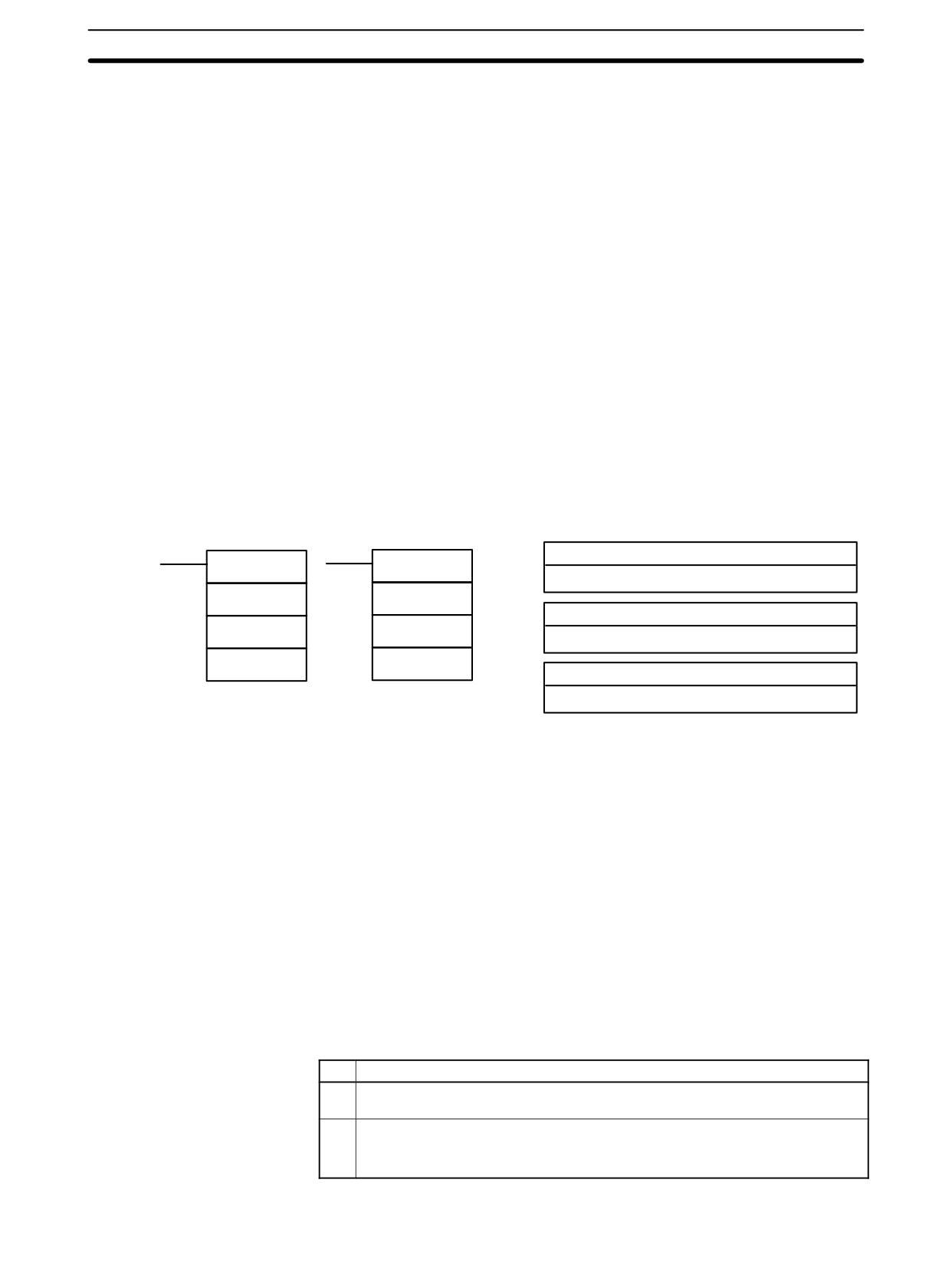
Pulse Output Instructions
Section
7-27
ue of the number of movement pulses will be used. (For example, if the number
of movement pulses is -500, a value of 500 will be used.)
Flags
ER:
A data area boundary is exceeded.
Indirectly addressed DM word is non-existent. (Content of *DM word is
not BCD, or the DM area boundary has been exceeded.)
P is not 000 or 010.
C is not 000 or 001. (C cannot be set to 001 when relative coordinates
are being used.)
The number of output pulses is not between -16,777,215 and
16,777,215.
PULS(65) is executed in an interrupt subroutine while a pulse I/O or
high-speed counter instruction (INI(61), PRV(62), CTBL(63),
SPED(64), PULS(65), ACC(--), PWM(--), or SYNC(--)) is being
executed in the main program.
After PULS(65) is executed, the absolute value of the number of move-
ment pulses is not between 1 and 16,777,215.
7-27-2
SPEED OUTPUT- SPED(64)
Ladder Symbols
Operand Data Areas
P: Port specifier
SPED(64)
@SPED(64)
001 or 010
P
P
M: Output mode
M
M
000 or 001
F
F
F: Target frequency
IR, SR, AR, DM, HR, LR, #
Limitations
This instruction is supported by the CPM1A and CPM2A/CPM2C PCs with
transistor outputs only.
In the CPM1A: F must be BCD, #0000 or #0002 to #0200.
In the CPM2A/CPM2C: F must be BCD, #0000 or #0001 to #1000.
DM 6144 to DM 6655 cannot be used for F.
Description
SPED(64) is used to set the output pulse frequency and start the pulse output
from the specified output bit. When the execution condition is OFF, SPED(64) is
not executed. When the execution condition is ON, SPED(64) sets the pulse fre-
quency F for the output bit specified by P. M determines the output mode.
In general, SPED(64) should be executed just once each time that the frequency
needs to be set; use the differentiated variation (@SPED(64)) or an input condi-
tion that is ON for just one cycle.
Note Refer to 2-5 Pulse Output Functions for more details.
Port Specifier (P)
The port specifier indicates the output bit where the pulses will be output.
P
Pulse output location(s)
000
Single-phase pulse output 0 without acceleration or deceleration (output
01000)
010
Single-phase pulse output 1 without acceleration or deceleration (output
01001)
This setting is supported by CPM2A/CPM2C PCs only.
485
Pulse Output Instructions
Section
7-27
Output Mode (M)
The value of M determines the output mode.
M
Pulse type
000
Independent mode
001
Continuous mode
Operation in independent mode and continuous mode is described below.
Target Frequency (F)
The 4-digit BCD value of F sets the pulse frequency in units of 10 Hz, as shown
below. Setting F to 0000 will stop the pulse output from the specified output bit.
PC
Possible values of F
CPM1A
0000 (stops pulse output) or 0002 to 0200 (20 Hz to 2 kHz)
CPM2A/CPM2C
0000 (stops pulse output) or 0001 to 1000 (10 Hz to 10 kHz)
General Operation
The pulse output started by SPED(64) will continue until one of the following oc-
curs:
1, 2, 3...
1. The INI(61) instruction is executed with C=003.
2. In independent mode, the number of output pulses specified by PULS(65) is
reached. (Execute PULS(65) before SPED(64).)
3. SPED(64) is executed again with the target frequency, F, set to #0000.
4. The PC is switched to PROGRAM mode.
Pulses can be output simultaneously and independently from two output bits.
When outputting pulses in independent mode, specify the number of pulses be-
forehand by executing PULS(65). The number of output pulses must be speci-
fied again with PULS(65) each time that the pulse output has been stopped.
The frequency cannot be changed with SPED(64) when pulses are already be-
ing output from the specified output bit by ACC(--) or PWM(--). An error will
occur and SR 25503 will be turned ON if SPED(64) is executed under these cir-
cumstances.
Operation in Independent
In independent mode, just the number of output pulses set by PULS(65) will be
Mode
output. The number of output pulses must be specified by executing PULS(65)
before executing SPED(64). (Pulses won’t be output if the number of output
pulses has not been specified in advance.)
When the calculated number of movement pulses is negative, the absolute val-
ue of the number of movement pulses will be used. (For example, if the number
of movement pulses is -500, a value of 500 will be used.)
Pulse frequency
Time
486
Pulse Output Instructions
Section
7-27
Operation in Continuous
In continuous mode, pulses will be output indefinitely until stopped by executing
Mode
INI(61) with C=003, executing SPED(64) again with F=0000, or switching the
PC to PROGRAM mode.
Pulse frequency
Time
Flags
ER:
A data area boundary is exceeded.
Indirectly addressed DM word is non-existent. (Content of *DM word is
not BCD, or the DM area boundary has been exceeded.)
P is not 000 or 010, M is not 000 or 001, or F is not 0000 to 1000.
SPED(64) is executed in an interrupt subroutine while a pulse I/O or
high-speed counter instruction (INI(61), PRV(62), CTBL(63),
SPED(64), PULS(65), ACC(--), PWM(--), or SYNC(--)) is being
executed in the main program.
7-27-3
ACCELERATION CONTROL - ACC(--)
Ladder Symbols
Operand Data Areas
P: Port specifier
ACC(--)
@ACC(--)
000
P
P
M: Mode specifier
M
M
000, 002, or 010 to 013
C
C
C: First control word
IR, SR, AR, DM, HR, LR
Limitations
This instruction is available in the CPM2A/CPM2C only.
P must be 001 or 002 and M must be 000 to 003.
C to C+3 must be in the same data area.
Description
ACC(--) is used to specify the acceleration/deceleration rate and start the pulse
output for a pulse output with trapezoidal acceleration and deceleration.
In general, ACC(--) should be executed just once each time that the accelera-
tion/deceleration rate needs to be set; use the differentiated variation
(@ACC(--)) or an input condition that is ON for just one cycle.
Note Refer to 2-5 Pulse Output Functions for more details.
Port Specifier (P)
Always set the port specifier to 000. The 000 setting specifies single-phase
pulse output 0 with trapezoidal acceleration and deceleration.
487
Pulse Output Instructions
Section
7-27
Mode Specifier (M)
The value of M determines the output mode.
M
Mode
Note
000
Independent mode and up/down pulse output mode
---
002
Independent mode and pulse + direction output mode
---
010
CW (continuous mode and up/down pulse output mode)
CW: Clockwise
011
CCW (continuous mode and up/down pulse output mode)
CCW: Counter-
012
CW (continuous mode and pulse + direction output mode)
clockwise
013
CCW (continuous mode and pulse + direction output mode)
In independent mode, the output direction is set when PULS(65) is executed.
Control Words (C, C+1, and C+2)
The 3 control words indicate the acceleration rate, target frequency, and decel-
eration rate. (Each frequency is set in multiples of 10 Hz.)
Word
Function
C
The content of C determines the acceleration rate.
During acceleration, the output frequency is increased by the amount set in
C every 10 ms. C must be BCD from 0001 to 1000 (10 Hz to 10 kHz).
C+1
The content of C+1 specifies the target frequency.
C+1 must be BCD from 0001 to 1000 (10 Hz to 10 kHz).
C+2
The content of C+2 determines the deceleration rate.
During deceleration, the output frequency is decreased by the amount set
in C+2 every 10 ms. C must be BCD from 0001 to 1000 (10 Hz to 10 kHz).
General Operation
Two output bits are required for pulse outputs controlled by ACC(--).
Up/down pulse output mode
IR 01000 (CW operation)
IR 01001 (CCW operation)
Pulse + direction output mode
IR 01000 (Pulse output)
IR 01001 (Direction specifier)
The pulse output will start when ACC(--) is executed and the output frequency
will be increased every 10 ms by amount specified in control word C. When the
target frequency (specified in C+1) is reached, acceleration is stopped and the
pulse output continues at a constant frequency.
When the pulse output is operating with trapezoidal acceleration and decelera-
tion, the pulse output can be stopped by one of the following methods.
1, 2, 3...
1. Execute the INI(61) instruction with C=003. (Immediate stop)
2. In independent mode, the number of output pulses specified by PULS(65) is
reached. (Decelerates to a stop.)
3. ACC(--) is executed with the target frequency (in C+1) set to 0000.
a) When pulses are being output in independent mode, the output will de-
celerate to a stop at the deceleration rate set when the pulse output was
started.
b) When pulses are being output in continuous mode, the output will decel-
erate to a stop at the specified deceleration rate.
4. Switch the PC to PROGRAM mode. (Immediate stop)
488
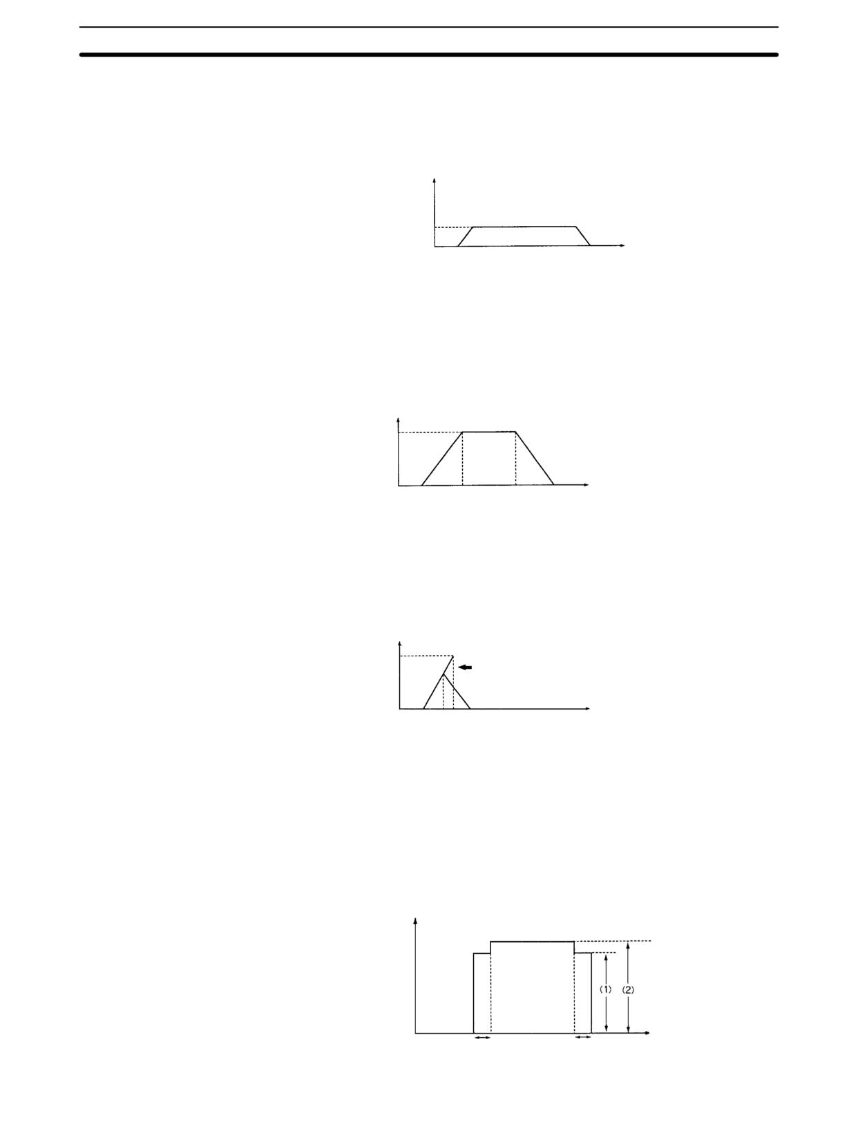
Pulse Output Instructions
Section
7-27
Operation in Independent
In independent mode, just the number of output pulses set by PULS(65) will be
Mode
output. The number of output pulses must be specified by executing PULS(65)
before executing ACC(--). (Pulses won’t be output if the number of output
pulses has not been specified in advance.)
Pulse frequency
Time
The number of output pulses must be specified again with PULS(65) each time
that the pulse output has been stopped.
In independent mode, the pulse output will begin decelerating at the point deter-
mined by the preset number of output pulses and the acceleration/deceleration
rates. The pulse output will stop when the preset number of output pulses has
been output.
Pulse frequency
Time
(The number of output pulses is always accurately output.)
If the number of output pulses required for acceleration and deceleration (the
time to reach the target frequency × the target frequency) exceeds the preset
number of pulses, the acceleration and deceleration will be cut short and the
pulse output will be triangular rather than trapezoidal.
Pulse frequency
Time
(The number of output pulses is always accurately output.)
If a high acceleration/deceleration rate and a low number of output pulses are
set, there will be effectively no acceleration and deceleration. (The pulse output
will operate at a constant speed.)
If the (target frequency ÷ acceleration/deceleration rate) is not an integer value,
the specified acceleration/deceleration rates will be increased or decreased. In
the following example, the acceleration and deceleration are 10-ms long, (1) is
the acceleration/deceleration rate, and (2) is the target frequency.
Pulse frequency
Time
10 ms
10 ms
489
Pulse Output Instructions
Section
7-27
Operation in Continuous
In continuous mode, pulses will be output indefinitely until stopped by executing
Mode
INI(61) with C=003, executing ACC(--) again with the target frequency (in C+1)
set to 0000, or switching the PC to PROGRAM mode.
Pulse frequency
Time
The following conditions apply when ACC(--) is executed while pulses are al-
ready being output with trapezoidal acceleration/deceleration.
• ACC(--) will have no effect if it is executed when the pulse output is accelerat-
ing or decelerating.
• When ACC(--) is executed while pulses are being output in continuous mode,
the frequency can be changed to a new target frequency (0001 to 1000: 10 Hz
to 10 kHz) with the set acceleration/deceleration rates.
• If pulses are being output in independent mode, the pulse output can be decel-
erated to a stop while by executing ACC(--) with the target frequency (in C+1)
set to 0000. The acceleration/deceleration rates and number of output pulses
won’t be checked or changed.
• ACC(--) will have no effect if it is executed when pulses are being output by
one of the following instructions. (The pulse output will continue unchanged.)
Pulses being output from output 01000 by SPED(64).
Pulses being output from output 01001 by SPED(64).
Pulses being output from output 01000 by PWM(--).
Pulses being output from output 01001 by PWM(--).
Note Be sure to check the status of the pulse output before executing ACC(--).
Flags
ER:
A data area boundary is exceeded.
Indirectly addressed DM word is non-existent. (Content of *DM word is
not BCD, or the DM area boundary has been exceeded.)
P is not 000.
M is not 000, 002, or 010 to 013. (The mode specifier is read only when
starting the pulse output.)
ACC(--) is executed for a bit from which pulses are already being out-
put by PWM(--) or SPED(64).
ACC(--) is executed in an interrupt subroutine while a pulse I/O or high-
speed counter instruction (INI(61), PRV(62), CTBL(63), SPED(64),
PULS(65), ACC(--), PWM(--), or SYNC(--)) is being executed in the
main program.
7-27-4
PULSE WITH VARIABLE DUTY RATIO - PWM(--)
Ladder Symbols
Operand Data Areas
P: Port specifier
PWM(--)
@PWM(--)
000 or 010
P
P
F: Frequency
F
F
IR, SR, AR, DM, HR, LR, #
D
D
D: Duty ratio
IR, SR, AR, DM, HR, LR, #
490
Pulse Output Instructions
Section
7-27
Limitations
This instruction is available in the CPM2A/CPM2C only.
P must be 000 or 010, F must be BCD between 0001 and 9999, and D must be
BCD between 0001 and 0100.
Description
PWM(--) is used to output pulses with the specified duty ratio from the specified
output bit. The pulse output continues until PWM(--) is executed again with a
different duty ratio, INI(61) is executed with C=003, or the PC is switched to
PROGRAM mode.
In general, PWM(--) should be executed just once to start the pulse output; use
the differentiated variation (@PWM(--)) or an input condition that is ON for just
one cycle.
Variable duty-ratio pulses can be output simultaneously and independently from
two output bits.
When variable duty-ratio pulses are being output from an output bit and
PWM(--) is executed for that bit again with a different duty ratio, pulses will con-
tinue being output with the new duty ratio. The frequency cannot be changed.
PWM(--) cannot be executed for an output bit if pulses are already being output
from that bit by SPED(64) or ACC(--). An error will occur and SR 25503 will be
turned ON if PWM(--) is executed under these circumstances.
Note Refer to 2-5 Pulse Output Functions for more details.
Port Specifier (P)
The port specifier indicates the output bit where the pulses will be output.
P
Pulse output location(s)
000
Variable duty-ratio pulse output 0 (output 01000)
010
Variable duty-ratio pulse output 1 (output 01001)
Frequency (F)
The 4-digit BCD value of F sets the pulse frequency in units of 0.1 Hz. The fre-
quency can be set between 0001 and 9999 (0.1 to 999.9 Hz).
Duty Ratio (D)
The 4-digit BCD value of D specifies the duty ratio of the pulse output, i.e., the
percentage of time that the output is ON. The duty ratio can be set between 0001
and 0100 (1% to 100%). The duty ratio is 75% in the following diagram.
ton
ton
+ D (1% to 100%)
T
T
Flags
ER:
A data area boundary is exceeded.
Indirectly addressed DM word is non-existent. (Content of *DM word is
not BCD, or the DM area boundary has been exceeded.)
P is not 000 or 010, F is not BCD between 0001 and 9999, or D is not
BCD between 0001 and 0100. (The frequency setting in F is read only
when starting the pulse output.)
ACC(--) is executed for a bit from which pulses are already being out-
put by ACC(--) or SPED(64).
PWM(--) is executed in an interrupt subroutine while a pulse I/O or
high-speed counter instruction (INI(61), PRV(62), CTBL(63),
SPED(64), PULS(65), ACC(--), PWM(--), or SYNC(--)) is being
executed in the main program.
491
Pulse Output Instructions
Section
7-27
7-27-5
SYNCHRONIZED PULSE CONTROL - SYNC(--)
Ladder Symbols
Operand Data Areas
P1: Input port specifier
SYNC(--)
@SYNC(--)
000
P1
P1
P2: Output port specifier
P2
P2
000 or 010
C
C
C: Scaling factor
IR, SR, AR, DM, HR, LR, #
Limitations
This instruction is available in the CPM2A/CPM2C only.
P1 must be 000 and P2 must be 000 or 010.
Description
SYNC(--) takes the frequency of the input pulse received through the high-
speed counter inputs, multiplies it by a fixed scaling factor, and outputs pulses
from the specified output bit at the resulting frequency.
Output frequency = Input frequency × Scaling factor/100
In general, SYNC(--) should be executed just once each time that synchronized
pulse output control needs to be set; use the differentiated variation
(@SYNC(--)) or an input condition that is ON for just one cycle.
Note Refer to 2-5 Pulse Output Functions for more details.
Input Port Specifier (P1)
Always set P1 to 000.
Output Port Specifier (P2)
The value of P2 determines where the scaled pulse frequency is output.
P2
Pulse output location(s)
000
Synchronized pulse output 0 (output 01000)
010
Synchronized pulse output 1 (output 01001)
Scaling Factor (C)
The 4-digit BCD value of C sets the scaling factor by which the input frequency is
multiplied. The scaling factor can be set between 0001 and 1000 (1 to 1,000%).
PC Setup Settings and
The counter input mode for inputs 00000 and 00001 is set in bits 00 to 03 of
General Operation
DM 6642.
DM 6642 bits 00 to 03
High-speed counter setting
0
Differential phase mode (5 kHz)
1
Pulse + direction input mode (20 kHz)
2
Up/down input mode (20 kHz)
4
Increment mode (20 kHz)
Input Frequency Range
The input frequency range for the synchronized pulse control is set in bits 08 to
15 of DM 6642, as shown in the following table.
DM 6642 bits 08 to 15
Function of inputs 00000 and 00001
02
Use for synchronized pulse control (10 to 500 Hz)
03
Use for synchronized pulse control (20 Hz to 1 kHz).
04
Use for synchronized pulse control (300 Hz to 20 kHz).
Synchronized pulse control cannot be executed unless inputs 00000 to 00003
are set for synchronized pulse control in bits 08 to 15 (settings 02, 03, and 04).
An error will occur and SR 25503 will be turned ON if SYNC(--) is executed but
DM 6642 is not set for synchronized pulse control.
492

Special Instructions
Section
7-28
The high-speed counter function and pulse output functions cannot be used whi-
le synchronized pulse control is in operation. An error will occur and SR 25503
will be turned ON if a related pulse output instruction is executed to use one of
these functions while synchronized pulse control is being performed.
If the input frequency exceeds the maximum in the table above, the maximum
input frequency for that range will be used. If the input frequency falls below the
minimum, an input frequency of 0 Hz will be used.
Output Frequency Range
The output frequency range is 10 Hz to 10 kHz. If the calculated output frequen-
cy (input frequency × scaling factor/100) exceeds 10 kHz, pulses will be output at
10 kHz. If the calculated output frequency falls below 10 Hz, pulses will not be
output (0 Hz).
Changing the Scaling Factor or Output Port
The scaling factor can be changed while synchronized pulse control is in opera-
tion by executing SYNC(--) again with a different scaling factor, but the output
port specifier cannot be changed during operation.
Stopping the Synchronized Pulse Control Output
The synchronized pulse output can be stopped by executing INI(61) with C=005
or switching the PC to PROGRAM mode.
Flags
ER:
A data area boundary is exceeded.
Indirectly addressed DM word is non-existent. (Content of *DM word is
not BCD, or the DM area boundary has been exceeded.)
P1 is not 000, P2 is not 000 or 010, or C is not BCD between 0001 and
1000.
SYNC(--) is executed when bits 08 to 15 of DM 6642 are not set for
synchronized pulse control.
SYNC(--) is executed in an interrupt subroutine while a pulse I/O or
high-speed counter instruction (INI(61), PRV(62), CTBL(63),
SPED(64), PULS(65), ACC(--), PWM(--), or SYNC(--)) is being
executed in the main program.
7-28 Special Instructions
7-28-1
MESSAGE DISPLAY - MSG(46)
Ladder Symbols
Operand Data Areas
FM: First message word
MSG(46)
@MSG(46)
IR, SR, AR, DM, HR, LR
FM
FM
Limitations
DM 6649 to DM 6655 cannot be used for FM.
Description
When executed with an ON execution condition, MSG(46) reads eight words of
extended ASCII code from FM to FM+7 and displays the message on the Pro-
gramming Console. The displayed message can be up to 16 characters long,
i.e., each ASCII character code requires eight bits (two digits). Refer to Appen-
dix G for the ASCII codes. Japanese katakana characters are included in this
code.
If not all eight words are required for the message, it can be stopped at any point
by inputting “OD.” When OD is encountered in a message, no more words will be
read and the words that normally would be used for the message can be used for
other purposes.
493
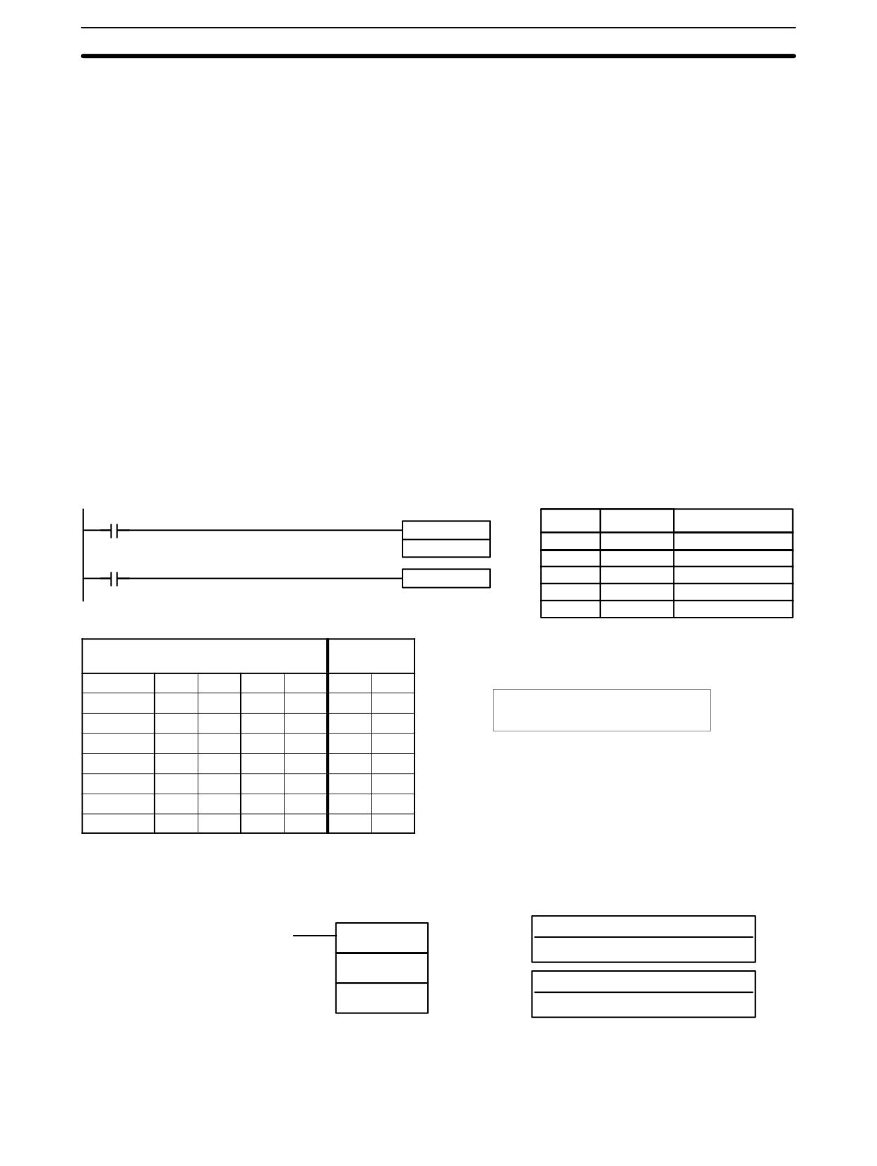
Special Instructions
Section 7-28
Message Buffering and
Up to three messages can be buffered in memory. Once stored in the buffer, they
Priority
are displayed on a first in, first out basis. Since it is possible that more than three
MSG(46)s may be executed within a single cycle, there is a priority scheme,
based on the area where the messages are stored, for the selection of those
messages to be buffered.
The priority of the data areas is as follows for message display:
LR > IR > HR > AR > TC > DM
In handling messages from the same area, those with the lowest ad-
dress values have higher priority.
In handling indirectly addressed messages (i.e. *DM), those with the
lowest final DM addresses have higher priority.
Clearing Messages
To clear a message, execute FAL(06) 00 or clear it via a Programming Console
or the Support Software.
If the message data changes while the message is being displayed, the display
will also change.
Flags
ER:
Indirectly addressed DM word is non-existent. (Content of *DM word is
not BCD, or the DM area boundary has been exceeded.)
Example
The following example shows the display that would be produced for the instruc-
tion and data given when 00000 was ON. If 00001 goes ON, a message will be
cleared.
00000
Address
Instruction
Operands
MSG(46)
00000
LD
00000
DM 0010
00001
MSG(46)
00001
FAL(06) 00
DM
0010
00002
LD
00001
00003
FAL(06)
00
DM contents
ASCII
equivalent
DM 0010
4
1
4
2
A
B
DM 0011
4
3
4
4
C
D
MSG
DM 0012
4
5
4
6
E
F
ABCDEFGHIJKLMNOP
DM 0013
4
7
4
8
G
H
DM 0014
4
9
4
A
I
J
DM 0015
4
B
4
C
K
L
DM 0016
4
D
4
E
M
N
DM 0017
4
F
5
0
O
P
7-28-2
I/O REFRESH - IORF(97)
Ladder Symbol
Operand Data Areas
St: Starting word
IORF(97)
IR 000 to IR 019
St
E: End word
E
IR 000 to IR 019
Note This instruction is not supported by SRM1(-V2) PCs.
Limitations
St must be less than or equal to E.
494
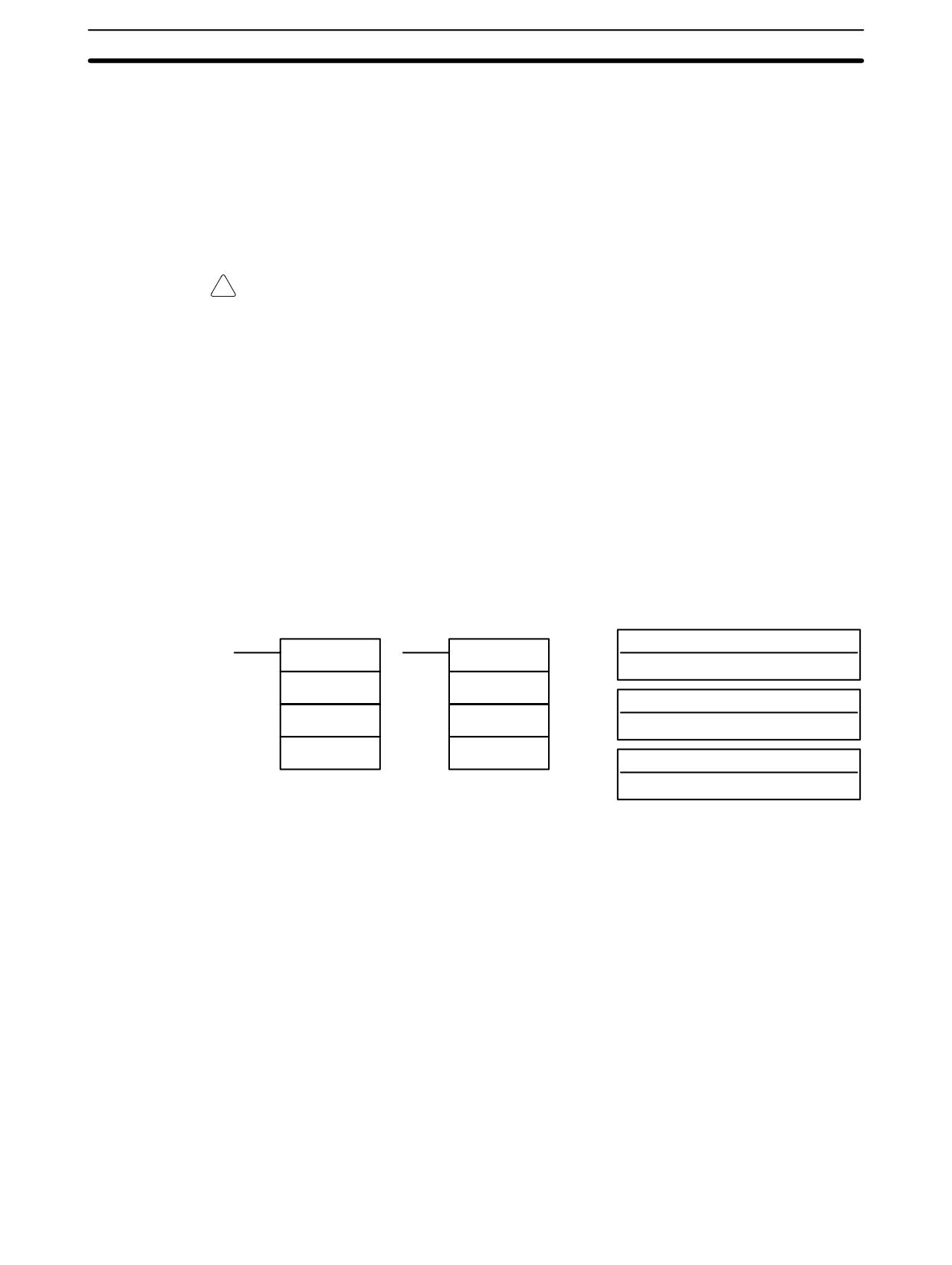
Special Instructions
Section 7-28
Description
To refresh I/O words, specify the first (St) and last (E) I/O words to be refreshed.
When the execution condition for IORF(97) is ON, all words between St and E
will be refreshed. This will be in addition to the normal I/O refresh performed dur-
ing the CPU Unit’s cycle.
(If St>E, IORF(97) will be treated as NOP(00).)
Normally, I/O refreshing is performed just once each cycle at the end of program
execution, but IORF(97) can be used to refresh I/O words immediately during
program execution.
!
Caution Although IORF(97) can be used in interrupt subroutines, you must be careful of
the interval between IORF(97) executions. If IORF(97) is executed to frequently,
a fatal system error may occur (FALS 9F), stopping operation. The interval be-
tween executions of IORF(97) should be at least 1.3 ms + total execution time of
the interrupt subroutine.
Flags
ER:
St or E is not within the allowed range (IR 000 to IR 019).
St is greater than E. (If St>E, IORF(97) will be treated as NOP(00).)
Flags
There are no flags affected by this instruction.
7-28-3
BIT COUNTER - BCNT(67)
Ladder Symbols
Operand Data Areas
N: Number of words (BCD)
BCNT(67)
@BCNT(67)
IR, SR, AR, DM, HR, TC, LR, #
N
N
SB: Source beginning word
SB
SB
IR, SR, AR, DM, HR, TC, LR
R
R
R: Destination word
IR, SR, AR, DM, HR, TC, LR
Note BCNT(67) is an expansion instruction in the CPM2A/CPM2C and SRM1(-V2).
The function code 67 is the factory setting and can be changed for if desired.
Limitations
N cannot be 0.
DM 6144 to DM 6655 cannot be used for R.
Description
When the execution condition is OFF, BCNT(67) is not executed. When the
execution condition is ON, BCNT(67) counts the total number of bits that are ON
in all words between SB and SB+(N-1) and places the result in R.
Flags
ER:
N is not BCD, or N is 0; SB and SB+(N-1) are not in the same area.
A DM address is used for SB, but SB through SB+(N-1) are not all in
read/write DM.
Indirectly addressed DM word is non-existent. (Content of *DM word is
not BCD, or the DM area boundary has been exceeded.)
EQ:
ON when the result is 0.
495
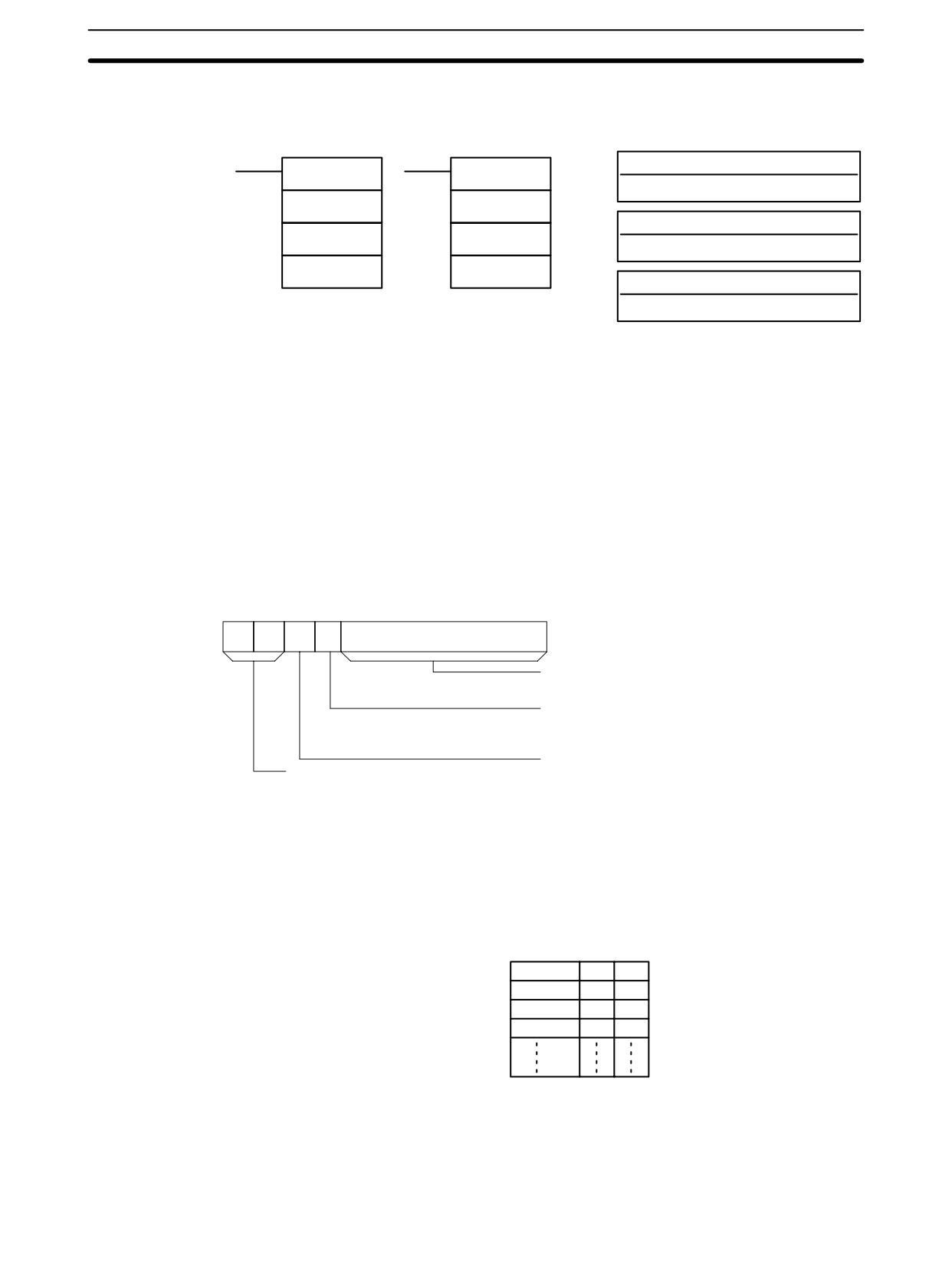
Special Instructions
Section
7-28
7-28-4
FRAME CHECKSUM - FCS(--)
Ladder Symbols
Operand Data Areas
C: Control data
FCS(--)
@FCS(--)
IR, SR, AR, DM, HR, LR, #
C
C
R1: First word in range
R1
R1
IR, SR, AR, DM, HR, TC, LR
D
D
D: First destination word
IR, SR, AR, DM, HR, LR
Limitations
This instruction is available in the CPM2A/CPM2C/SRM1(-V2) only.
The 3 rightmost digits of C must be BCD between 001 and 999.
DM 6144 to DM 6655 cannot be used for D.
Description
FCS(--) can be used to check for errors when transferring data through commu-
nications ports.
When the execution condition is OFF, FCS(--) is not executed. When the
execution condition is ON, FCS(--) calculates the frame checksum of the speci-
fied range by exclusively ORing either the contents of words R1 to R1+N-1 or the
bytes in words R1 to R1+N-1. The frame checksum value (hexadecimal) is then
converted to ASCII and output to the destination words (D and D+1).
The function of bits in C are shown in the following diagram and explained in
more detail below.
15
14
13
12
11
00
C:
Number of items in range (N, BCD)
001 to 999 words or bytes
First byte (when bit 13 is ON)
1 (ON): Rightmost
0 (OFF): Leftmost
Calculation units
Not used. Set to zero.
1 (ON): Bytes
0 (OFF): Words
Number of Items in Range
The number of items within the range (N) is contained in the 3 rightmost digits of
C, which must be BCD between 001 and 999.
Calculation Units
The frame checksum of words will be calculated if bit 13 is OFF and the frame
checksum of bytes will be calculated if bit 13 is ON.
If bytes are specified, the range can begin with the leftmost or rightmost byte of
R1. The leftmost byte of R1 will not be included if bit 12 is ON.
MSB LSB
R1
1
2
R1+1
3
4
R1+2
5
6
R1+3
7
8
When bit 12 is OFF the bytes will be ORed in this order: 1, 2, 3, 4,
When bit 12 is ON the bytes will be ORed in this order: 2, 3, 4, 5,
Conversion to ASCII
The byte frame checksum calculation yields a 2-digit hexadecimal value which is
converted to its 4-digit ASCII equivalent. The word frame checksum calculation
496
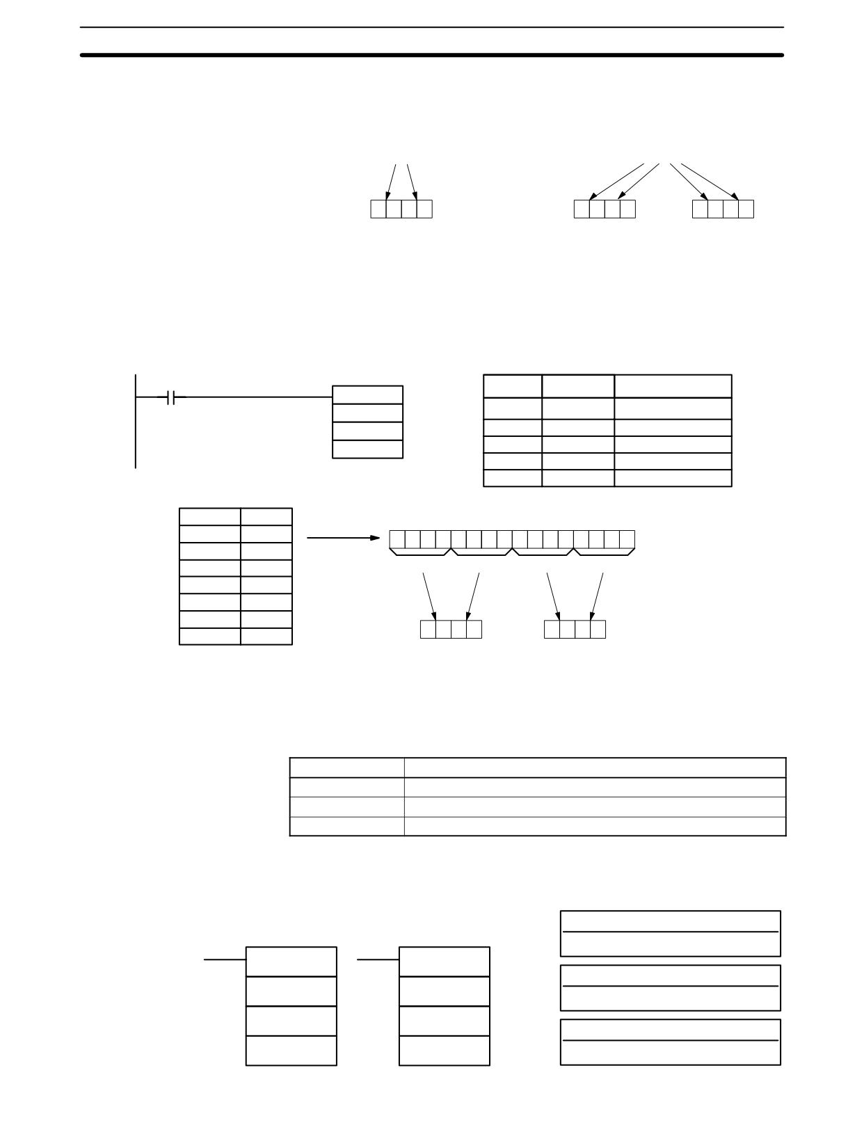
Interrupt Control Instructions
Section
7-29
yields a 4-digit hexadecimal value which is converted to its 8-digit ASCII equiva-
lent, as shown below.
Byte frame checksum value
Word frame checksum value
4A
F10B
D
3
4
4
1
D
4
6
3
1
D+1
3
0
4
2
Flags
ER:
Indirectly addressed DM word is non-existent. (Content of *DM word is
not BCD, or the DM area boundary has been exceeded.)
The number of items is not 001 to 999 BCD.
Example
When IR 00000 is ON in the following example, the frame checksum (0008) is
calculated for the 8 words from DM 0000 to DM 0007 and the ASCII equivalent
(30 30 30 38) is written to DM 0010 and DM 0011.
00000
Address
Instruction
Operands
@FCS(--)
#0008
00000
LD
00000
DM 0000
00001
@FCS(--)
#
0008
DM 0010
DM
0000
DM
0010
FCS
DM 0000
0001
calculation
DM 0001
0002
0
0
0
0
0
0
0
0
0
0
0
0
1
0
0
0
DM 0002
0003
DM 0003
0004
0
0
0
8
DM 0004
0005
ASCII code
DM 0005
0006
conversion
DM 0006
0007
DM 0010
3
0
3
0
DM 001
1
3
0
3
8
DM 0007
0008
7-29
Interrupt Control Instructions
This section describes the operation of INT(89) and STIM(69). For general infor-
mation on interrupt processing in CPM1/CPM1A, CPM2A/CPM2C, or
SRM1(-V2) PCs refer to the section shown in the following table.
PC
Reference
CPM1/CPM1A
See 2-3 CPM1/CPM1A Interrupt Functions.
CPM2A/CPM2C
See 2-1 CPM2A/CPM2C Interrupt Functions.
SRM1(-V2)
See 2-4 SRM1 Interrupt Functions.
7-29-1 INTERRUPT CONTROL - INT(89)
Operand Data Areas
Ladder Symbols
C1: Control code
# (000 to 004, 100, or 200)
INT(89)
@INT(89)
000: No function
C1
C1
000
000
000
C2: Control data
C2
C2
IR, SR, AR, DM, HR, TC, LR, #
497
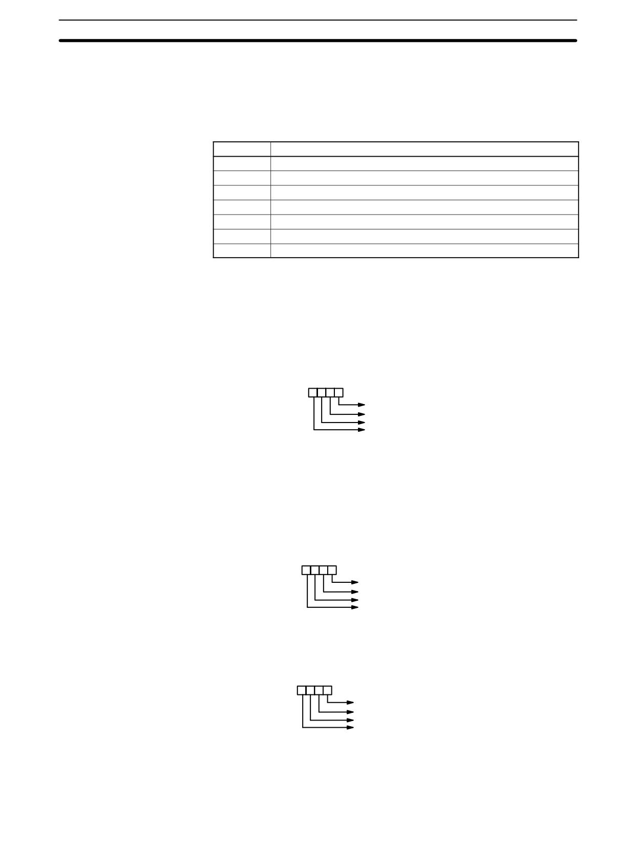
Interrupt Control Instructions
Section
7-29
Note
This instruction is not supported by SRM1(-V2) PCs.
Limitations
DM 6144 to DM 6655 cannot be used for C2 when C1=002.
Description
When the execution condition is OFF, INT(89) is not executed. When the execu-
tion condition is ON, INT(89) is used to control interrupts and performs one of the
seven functions shown in the following table depending on the value of C1.
C1
INT(89) function
000
Mask/unmask interrupt inputs
001
Clear interrupt inputs
002
Read current mask status of interrupt inputs
003
Restart decrementing counter and unmask interrupt
004*
Restart incrementing counter and unmask interrupt
100
Mask all interrupts
200
Unmask all interrupts
Note
*This setting can be used in CPM2A/CPM2C PCs only.
Mask/Unmask Interrupt
This function is used to mask and unmask interrupt inputs 00003 to 00006.
Inputs (C1=000)
Masked inputs are recorded, but ignored. When an input is masked, the interrupt
program for it will be run as soon as the bit is unmasked (unless it is cleared be-
forehand by executing INT(89) with C1=001).
Set the corresponding bit in C2 to 0 or 1 to unmask or mask an interrupt input.
Bits 00 to 03 correspond to 00003 to 00006. Bits 04 to 15 should be set to 0.
Word C2 bits:
3210
Interrupt input 00003 (0: unmask, 1: mask)
Interrupt input 00004 (0: unmask, 1: mask)
Interrupt input 00005 (0: unmask, 1: mask)
Interrupt input 00006 (0: unmask, 1: mask)
All of the interrupt inputs are masked at the start of PC operation, so the inputs
must be unmasked in order to be used.
Clear Interrupt Inputs
This function is used to clear interrupt inputs 00003 to 00006. Since interrupt in-
(C1=001)
puts are recorded, masked interrupts will be serviced as soon as the mask is re-
moved unless they are cleared first.
Set the corresponding bit in C2 to 1 to clear an I/O interrupt input. Bits 00 to 03
correspond to 00003 to 00006. Bits 04 to 15 should be set to 0.
Word C2 bits:
3210
Interrupt input 00003 (0: Do not clear, 1: clear)
Interrupt input 00004 (0: Do not clear, 1: clear)
Interrupt input 00005 (0: Do not clear, 1: clear)
Interrupt input 00006 (0: Do not clear, 1: clear)
Read Current Mask Status
This function reads the current mask status for interrupt inputs 00003 to 00006
(C1=002)
and writes that information to word C2. The corresponding bit will be ON if the
input is masked. (Bits 00 to 03 correspond to 00003 to 00006.)
Word C2 bits:
3210
Interrupt input 00003 (0: not masked, 1: masked)
Interrupt input 00004 (0: not masked, 1: masked)
Interrupt input 00005 (0: not masked, 1: masked)
Interrupt input 00006 (0: not masked, 1: masked)
Restart Counter and
These functions are used to restart interrupt inputs (counter mode) by refreshing
Unmask Interrupt
the counter SV (in SR 240 to SR 243) and unmasking the interrupt input (00003
(C1=003 or C1=004)
to 00006).
498

Interrupt Control Instructions
Section
7-29
Set C1=3 to restart decrementing counters or C1=4 (CPM2A/CPM2C PCs only)
to restart incrementing counters.
Set the corresponding bit in C2 to 0 to refresh the input’s counter SV and unmask
the interrupt. (Bits 00 to 03 correspond to 00003 to 00006.)
Word C2 bits:
3210
Interrupt input 00003 counter
Interrupt input 00004 counter
Interrupt input 00005 counter
Interrupt input 00006 counter
Use the differentiated variation (@INT(89)) or an input condition that is ON for
just one cycle when executing INT(89) with C1=003 or C1=004. The counter PV
will be reset to the SV if INT(89) is executed while the counter is operating, so the
interrupt will never be generated if INT(89) is executed every cycle.
When INT(89) is executed with C1=003 or C1=004 and the SV word contains a
non-zero SV (0001 to FFFF), the corresponding counter will begin operating
(decrementing or incrementing) and the corresponding interrupt will be enabled
in counter mode. When the count reaches the SV, an interrupt will be generated
and the PV will be returned to the SV, so interrupts will be generated repeatedly
until the counter is stopped.
Writing 0000 to a counter’s SV word (SR 240 to SR 243) and executing INT(89)
to refresh the SV will stop the counter and disable the corresponding interrupt.
To restart the counter, write the non-zero SV to its SV word and execute INT(89).
(The SV words are reset to 0000 at the start of operation, so the counter’s SV
must be written to its SV word from the ladder program.)
When an interrupt has already been enabled (unmasked), the SV cannot be re-
freshed just by writing a new value to the SV word. Refresh the SV by executing
INT(89) with C1=003 (C1=004 for an incrementing counter).
A counter mode interrupt can be masked by executing INT(89) with C1=000 and
the corresponding bit in C2 set to 1, but an input will operate in interrupt input
mode, not counter mode, when its corresponding bit in C2 is set to 0.
Masking or Unmasking All
All interrupts, including input interrupts, interval timer interrupts, and high-speed
Interrupts
counter interrupts, can be masked or unmasked as a group by executing
(C1=100 or C1=200)
INT(89) with C1=100 or C1=200. The masked inputs are recorded, but ignored.
The global mask is in addition to any masks on the individual types of interrupts.
Furthermore, clearing the masks for all interrupts does not clear the masks on
the individual types of interrupts, but restores them to the masked conditions that
existed before INT(89) was executed to mask them as a group.
Do not use INT(89) to mask interrupts unless it is necessary to temporarily mask
all interrupts. Always use INT(89) instructions in pairs to do so, using the first
INT(89) instruction to mask all interrupts and the second one to unmask all inter-
rupts.
INT(89) cannot be used to mask and unmask all interrupts from within interrupt
routines.
Masking Interrupts (C1=100)
Use the INT(89) instruction with C1=100 to mask all interrupts.
(@)INT(89)
100
000
000
If an interrupt is generated while interrupts are masked, interrupt processing will
not be executed but the interrupt will be recorded for the input, interval timer, and
high-speed counter interrupts. The interrupts will then be serviced as soon as
interrupts are unmasked.
499
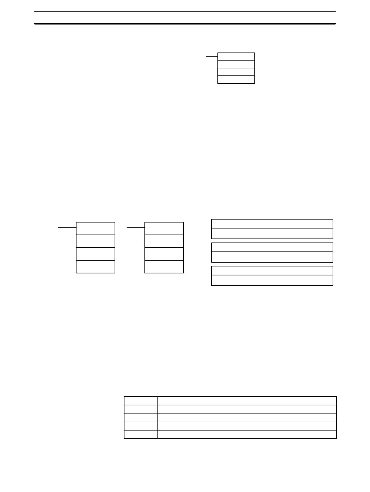
Interrupt Control Instructions
Section
7-29
Unmasking Interrupts (C1=200)
Use the INT(89) instruction with C1=200 to unmask interrupts as follows:
(@)INT(89)
200
000
000
Flags
ER:
A data area boundary is exceeded.
Indirectly addressed DM word is non-existent. (Content of *DM word is
not BCD, or the DM area boundary has been exceeded.)
C1 is not 000 to 004,100, or 200.
C2 is not 0000 to 000F.
INT(89) is executed with C1=100 or C1=200 while an interrupt program
was being executed.
INT(89) is executed with C1=100 when all inputs were already masked.
C1=200 when inputs were not all unmasked.
7-29-2
INTERVAL TIMER - STIM(69)
Ladder Symbols
Operand Data Areas
C1: Control data #1
STIM(69)
@STIM(69)
000 to 008, 010 to 012
C1
C1
C2: Control data #2
C2
C2
IR, SR, AR, DM, HR, TC, LR, #
C3
C3
C3: Control data #3
IR, SR, AR, DM, HR, TC, LR, #
Note
STIM(69) is an expansion instruction in the CPM2A/CPM2C and SRM1(-V2).
The function code 69 is the default setting and can be changed if desired.
Limitations
C1 must be 000, 003, 006. or 010.
If C1 is 000 or 003, C3 represents a BCD subroutine number up to 0049.
If C1 is 006, constants cannot be used for C2 or C3.
If C1 is 010, both C2 and C3 must be set to 000.
Description
STIM(69) is used to control the interval timers by performing four basic func-
tions: starting the timer for a one-shot interrupt, starting the timer for scheduled
interrupts, reading the timer’s PV, and stopping the timer. Set the value of C1 to
specify which of these functions will be performed, as shown in the following
table. Refer to Section 2 Special Features for more detailed descriptions of using
interval timer interrupts. STIM(69) is also described in more detail after the table.
C1 value
Function
000
Starts the one-shot interrupt timer.
003
Starts the scheduled interrupt timer.
006
Reads the timer PV.
010
Stops the timer.
Starting Interrupt Timers
Set C1=000 to activate the one-shot interrupt timer. Set C1=003 to start the
(C1= 000 or 003)
scheduled interrupt timer.
500
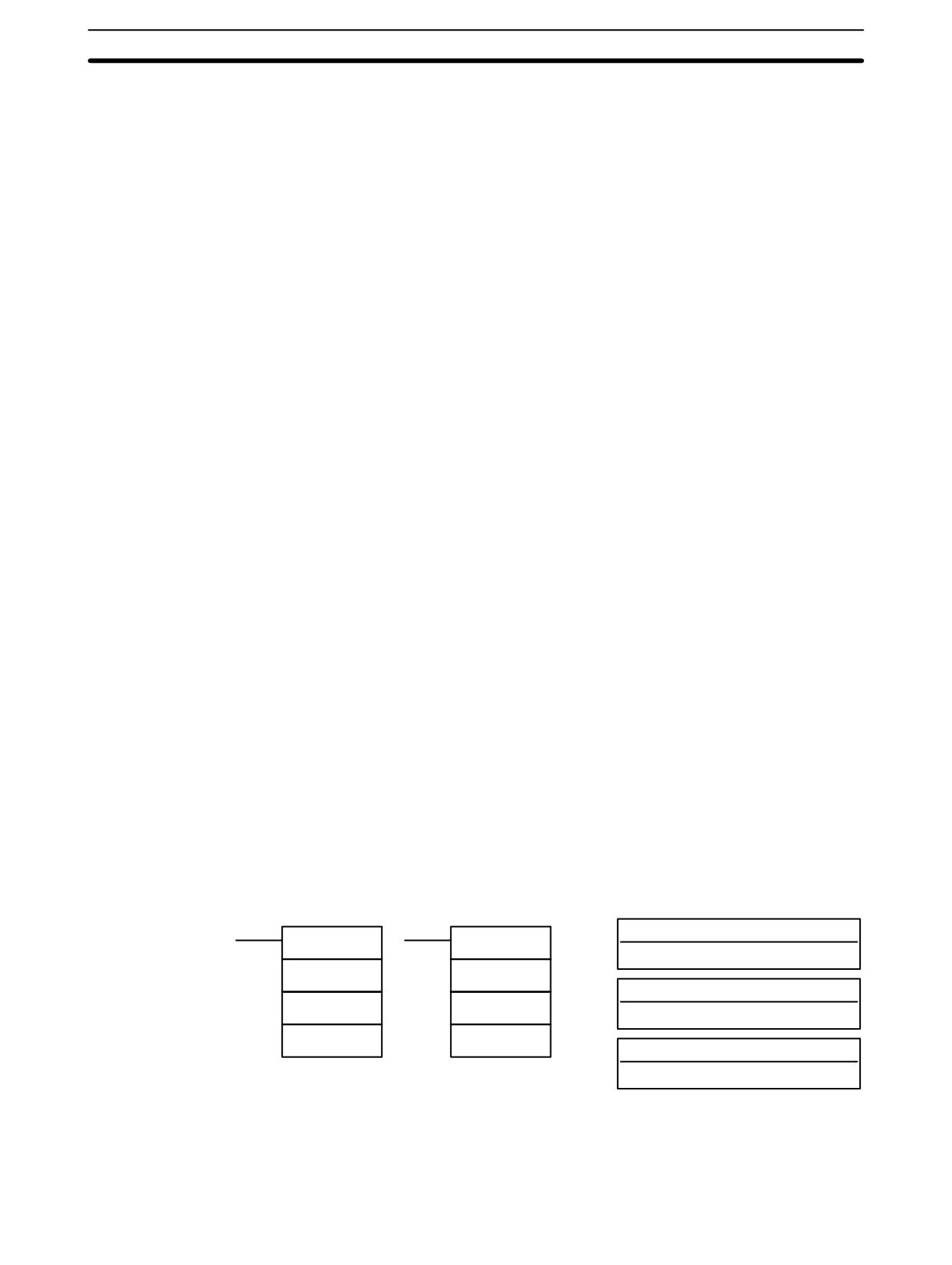
Communications Instructions
Section
7-30
C2, which specifies the timer’s SV, can be a constant or the first of two words
containing the SV. The settings are slightly different depending on the method
used.
C2 = Constant
If C2 is a constant, it specifies the SV of the decrementing counter in BCD. The
setting range is 0000 to 9999 (0 to 9.999 ms). (The timing units are fixed at 1 ms.)
C3 specifies subroutine number: 0000 to 0049.
C2 = Word Address
If C2 is a word address, the content of C2 contains the SV of the decrementing
counter (BCD, 0000 to 9999).
The content of C2+1 specifies the timing units (BCD, 0005 to 0320) in units of
0.1 ms. The decrementing time interval can thus be 0.5 to 32 ms.
The timer SV is: (the content of C2) × (the content of C2+1) × 0.1 ms.
C3 specifies subroutine number: 0000 to 0049.
Reading the Timer PV
Set C1=006 to read the timer PV.
(C1=006)
C2 specifies the first of two destination words that will receive the timer’s PV. C2
receives the number of times the decrementing counter has been decremented
(hexadecimal, 0000 to 9999) and C2+1 receives the timing units (BCD in 0.1 ms
units).
C3 specifies the destination word that receives the time which has elapsed since
the last time the timer was decremented (BCD in 0.1 ms units).
Note The time that has elapsed since the timer was started is computed as follows:
((Content of C2) × (Content of C2+1)) + ((Content of C3)) × 0.1 ms
Stopping the Timer
Set C1=010 to stop the timer. C2 and C3 have no function and should both be set
(C=010)
to 000.
Flags
ER:
C1 is not 000, 003, 006, or 010.
A specified subroutine number is not between 0000 and 0049.
Indirectly addressed DM word is non-existent. (Content of *DM word is
not BCD, or the DM area boundary has been exceeded.)
A data area boundary has been exceeded.
7-30 Communications Instructions
7-30-1
RECEIVE - RXD(47)
Ladder Symbols
Operand Data Areas
D: First destination word
RXD(47)
@RXD(47)
IR, SR, AR, DM, HR, TC, LR
D
D
C: Control word
C
C
#
N
N
N: Number of bytes
IR, SR, AR, DM, HR, TC, LR, #
Limitations
This instruction is available in the CPM2A/CPM2C and SRM1(-V2) only.
D and D+(N÷2)-1 must be in the same data area.
DM 6144 to DM 6655 cannot be used for D or N.
501
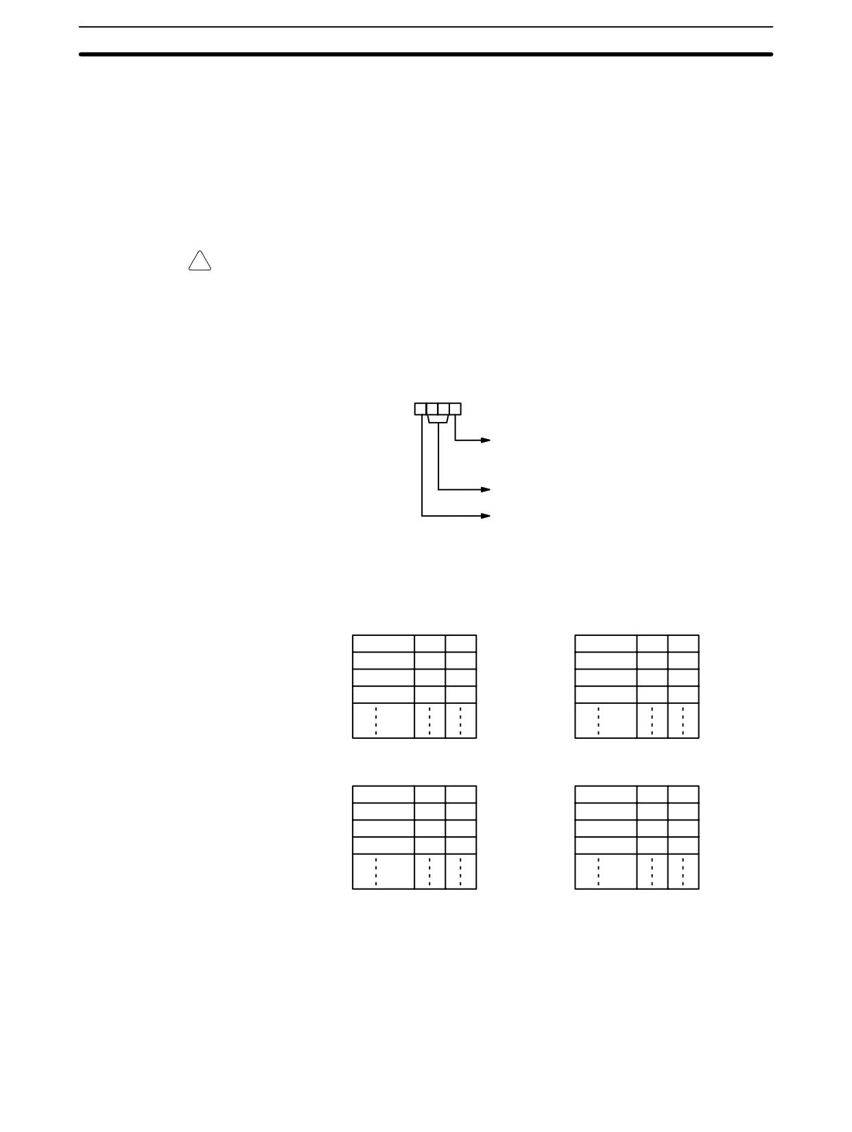
Communications Instructions
Section 7-30
N must be BCD from #0000 to #0256. (#0000 to #0061 in Host Link mode)
Description
When the execution condition is OFF, RXD(47) is not executed. When the
execution condition is ON, RXD(47) reads N bytes of data received at the port
specified in the control word, and then writes that data in words D to D+(N÷2)-1.
Up to 256 bytes of data can be read at one time.
If fewer than N bytes are received, the amount received will be read.
Note
Refer to 4-1Communications Functions for details on using the RXD(47) instruc-
tion, setting communications protocol in the PC Setup, etc.
!
Caution
The PC will be incapable of receiving more data once 256 bytes have been re-
ceived if received data is not read using RXD(47). Read data as soon as pos-
sible after the Reception Completed Flag is turned ON (AR 0806 for the
RS-232C port, AR 0814 for the peripheral port.)
Control Word
The value of the control word determines the port from which data will be read
and the order in which data will be written to memory.
Digit number:
3210
Byte order
0: Most significant bytes first, same word
1: Least significant bytes first, same word
Not used. (Set to 00.)
Port
0: RS-232C port.
1: Peripheral port.
The order in which data is written to memory depends on the value of digit 0 of C.
Eight bytes of data 12345678... will be written in the following manner:
Digit 0 = 0
Digit 0 = 1
MSB LSB
MSB LSB
D
1
2
D
2
1
D+1
3
4
D+1
4
3
D+2
5
6
D+2
6
5
D+3
7
8
D+3
8
7
Digit 0 = 2
Digit 0 = 3
MSB LSB
MSB LSB
D
1
D
1
D+1
2
3
D+1
2
3
D+2
4
5
D+2
4
5
D+3
6
7
D+3
6
7
Flags
ER:
The settings in C are not correct.
N is greater than 256.
The PC Setup is not set for no-protocol mode.
RXD(47) is already being executed.
AR 08: AR 0806 will be turned ON when data has been received normally at the
RS-232C port. Reset when RXD(47) is executed.
502
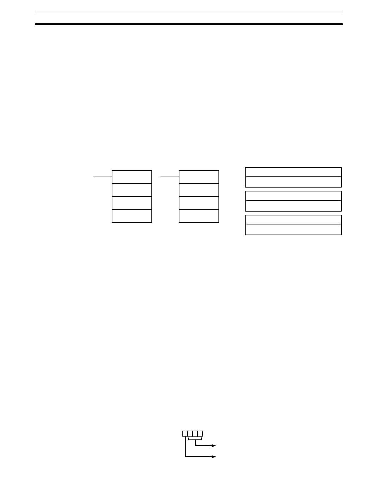
Communications Instructions
Section
7-30
AR 0814 will be turned ON when data has been received normally at the
peripheral port. Reset when RXD(47) is executed.
AR 09: Contains the number of bytes received at the RS-232C port. Reset to
0000 when RXD(47) is executed.
AR 10: Contains the number of bytes received at the peripheral port. Reset to
0000 when RXD(47) is executed.
Note Communications flags and counters can be cleared either by specifying 0000 for
N or using the Port Reset Bits (SR 25208 for peripheral port and SR 25209 for
RS-232C port.)
7-30-2
TRANSMIT - TXD(48)
Ladder Symbols
Operand Data Areas
S: First source word
TXD(48)
@TXD(48)
IR, SR, AR, DM, HR, TC, LR
S
S
C: Control word
C
C
#
N
N
N: Number of bytes
IR, SR, AR, DM, HR, TC, LR, #
Limitations
This instruction is available in the CPM2A/CPM2C and SRM1(-V2) only.
S and S+(N÷2)-1 must be in the same data area.
DM 6144 to DM 6655 cannot be used for S or N.
N must be BCD from #0000 to #0256. (#0000 to #0061 in Host Link mode)
Description
When the execution condition is OFF, TXD(48) is not executed. When the
execution condition is ON, TXD(48) reads N bytes of data from words S to
S+(N÷2)-1, converts it to ASCII, and outputs the data from the specified port.
TXD(48) operates differently in Host Link mode and RS-232C mode, so these
modes are described separately.
Note
1. Flag AR 0805 will be ON when the PC is capable of transmitting data
through the RS-232C port and AR 0813 will be ON when the PC is capable
of transmitting data through the peripheral port.
2. Refer to 4-1 Communications Functions for details on using the TXD(48)
instruction, setting communications protocol in the PC Setup, etc.
Host Link Mode
N must be BCD from #0000 to #0061 (i.e., up to 122 bytes of ASCII). The value of
the control word determines the port from which data will be output, as shown
below.
Digit number:
3210
Not used. (Set to 000.)
Port
0: Specifies RS-232C port.
1: Specifies peripheral port.
503
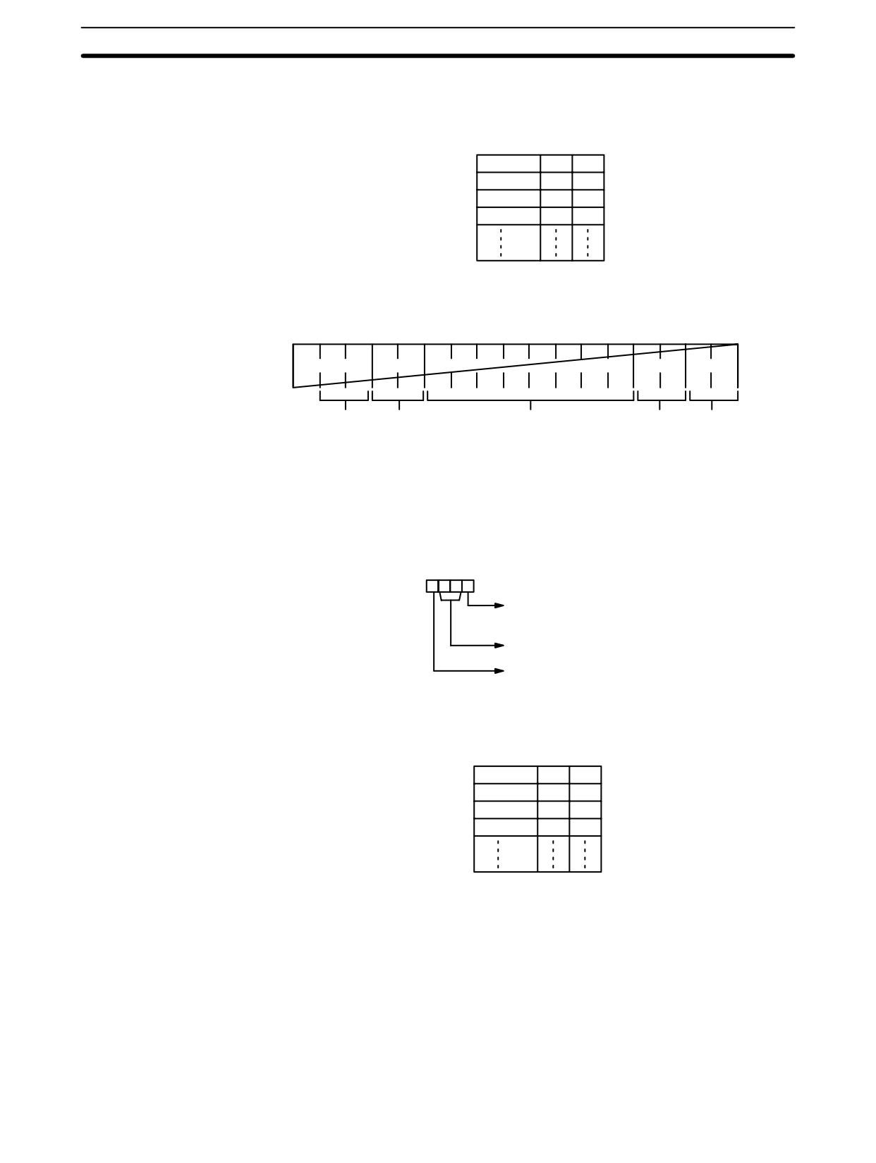
Communications Instructions
Section
7-30
The specified number of bytes will be read from S through S+(N/2)-1, converted
to ASCII, and transmitted through the specified port. The bytes of source data
shown below will be transmitted in this order: 12345678...
MSB LSB
S
1
2
S+1
3
4
S+2
5
6
S+3
7
8
The following diagram shows the format for Host Link command (TXD) sent from
the CPM2A/CPM2C. The CPM2A/CPM2C automatically attaches the prefixes
and suffixes, such as the node number, header, and FCS.
@
E X
∗ CR
Node
Header
Data (122 ASCII characters max.)
FCS Terminator
number code
RS-232C Mode
N must be BCD from #0000 to #00256. The value of the control word determines
the port from which data will be output and the order in which data will be written
to memory.
Control Word
The value of the control word determines the port from which data will be read
and the order in which data will be written to memory.
Digit number:
3210
Byte order
0: Most significant bytes first
1: Least significant bytes first
Not used. (Set to 00.)
Port
0: Specifies RS-232C port.
1: Specifies peripheral port.
The specified number of bytes will be read from S through S+(N÷2)-1 and trans-
mitted through the specified port.
MSB LSB
S
1
2
S+1
3
4
S+2
5
6
S+3
7
8
When digit 0 of C is 0, the bytes of source data shown above will be transmitted in
this order: 12345678...
When digit 0 of C is 1, the bytes of source data shown above will be transmitted in
this order: 21436587...
Note When start and end codes are specified the total data length should be 256 bytes
max., including the start and end codes.
Flags
ER:
The settings in C are not correct.
N is greater than 256 for no-protocol mode or greater than 61 for Host
Link mode.
504
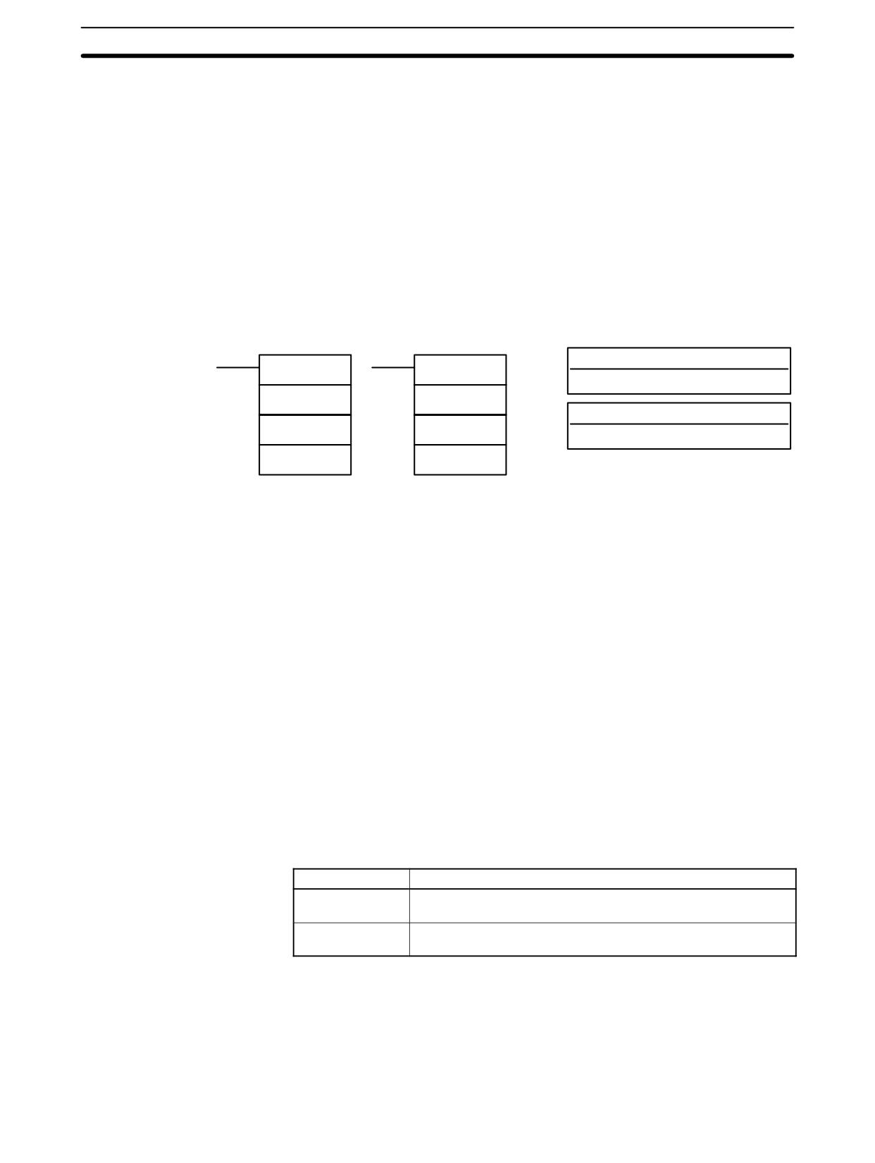
Communications Instructions
Section
7-30
The PC Setup is not set for the correct communications mode.
Indirectly addressed DM word is non-existent. (Content of *DM word is
not BCD, or the DM area boundary has been exceeded.)
TXD(48) is already being executed.
AR 08: AR 0805 will be turned ON when it is possible to transmit through the
RS-232C port. AR 0813 will be turned ON when it is possible to transmit
through the peripheral port.
7-30-3
CHANGE RS-232C SETUP - STUP(--)
Ladder Symbols
Operand Data Areas
N: RS-232C port specifier
STUP(--)
@STUP(--)
000
N
N
S: First source word
S
S
IR, SR, AR, DM, HR, LR, #
-
-
The third operand is ignored.
Limitations
This instruction is available in the CPM2A/CPM2C and SRM1(-V2) only.
N must be 000.
S and S+4 must be in the same data area.
(S can be set to #0000 to change the RS-232C settings to their defaults.)
STUP(--) can’t be executed within an interrupt subroutine.
Description
When the execution condition is OFF, STUP(--) is not executed. When the
execution condition is ON, STUP(--) changes the PC Setup settings for the
built-in RS-232C port. The settings are changed in the PC Setup, but they are
not written to flash memory until the PC is switched to PROGRAM mode (from
RUN or MONITOR mode) or the PC is turned OFF and then ON again.
In CPM2A/CPM2C and SRM1(-V2) PCs, N must be 000 because STUP(--) can
change the RS-232C Setup for the built-in RS-232C port (DM 6645 to DM 6649)
only.
If S is a word address, the contents of S through S+4 are copied to DM 6645 to
DM 6649.
If S is input as the constant #0000, the settings for the built-in RS-232C port are
returned to their default values.
S
Function
Word address
The contents of S through S+4 are copied to DM 6645 through
DM 6649.
Constant (#0000)
The settings in DM 6645 through DM 6649 are returned to their
default values.
Note
1. The Changing RS-232C Setup Flag (SR 25312) will be ON while STUP(--)
is being executed; it is turned OFF when STUP(--) is completed.
2. In the CPM2A/CPM2C, an error will occur and STUP(--) will not be execut-
ed if the Communications Switch on the front of the CPU Unit is ON. When
this switch is ON, RS-232C communications are governed by the default
settings.
505