FANUC R-30iB Plus CONTROLLER, iRVision 2D Camera Application. OPERATOR'S MANUAL - page 4
Setup
2. 2D MULTI VIEW VISION PROCESS
2.4.3.1 Vision process creation
1
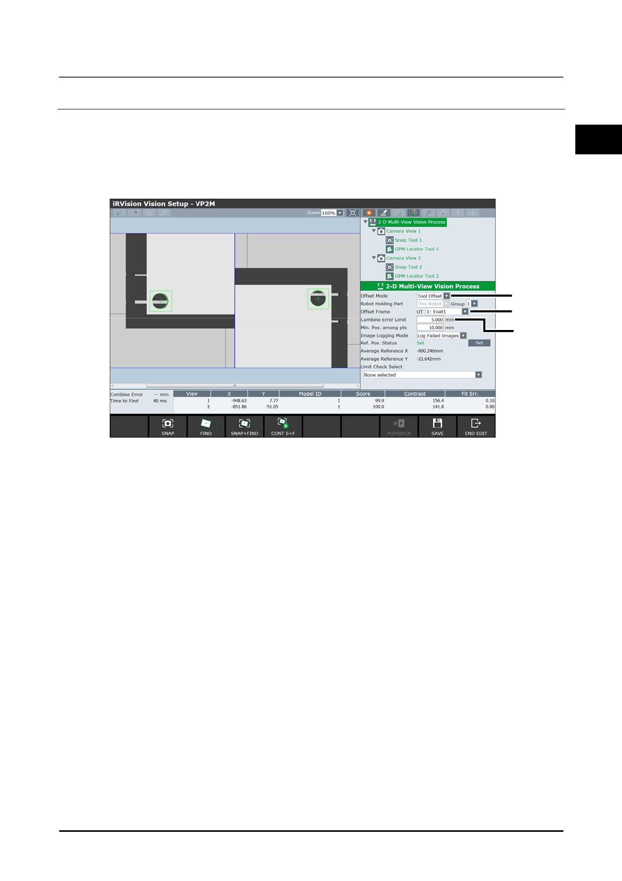
Create a vision process for [2-D Multi-View Vision Process].
For details of vision process creation, refer to Setup Edition Subsection 1.3.1.1, "Create" in "R-30iB
2
Plus CONTROLLER iRVision OPERATOR’S MANUAL(Reference) B-83914EN".
2
On the vision data list screen, when the created vision process is selected and clicked [Edit], the
vision data edit screen will appear.
3
4
5
3
From the [Offset Mode] drop-down box, select [Tool Offset].
4
From the [Offset Frame] drop-down box, select the tool frame to set.
Select the frame number specified in Setup Edition Subsection 2.4.2, "Offset Frame Setting."
5
Enter [Combine Error Limit] in the text box as required.
B-83914EN-2/01
73
2. 2D MULTI VIEW VISION PROCESS
Setup
2.4.3.2 Camera view teaching
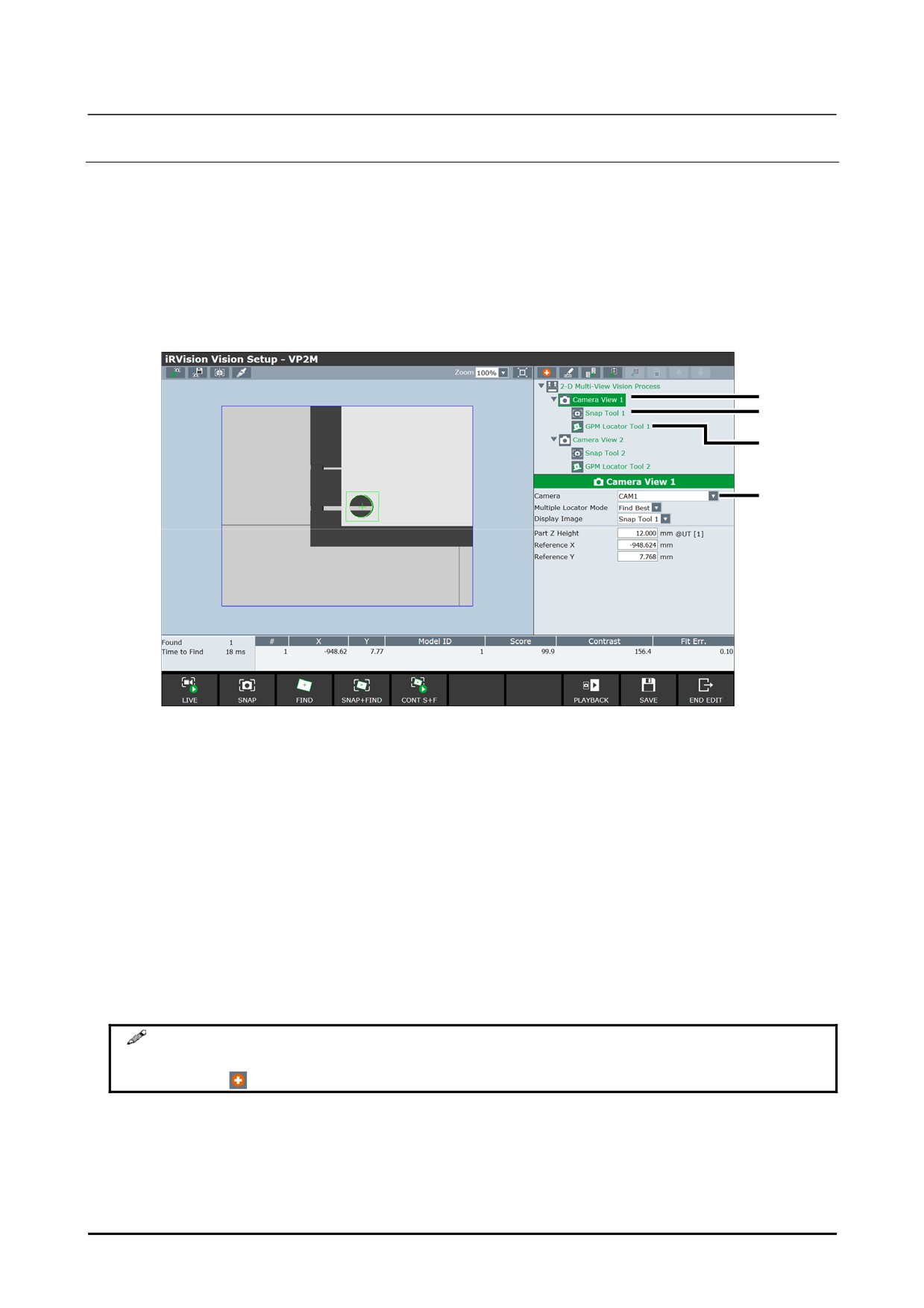
Teach the snap tool and the locator tool such as GPM Locator Tool, for each camera view.
1
Grip a workpiece with the robot.
2
Move the robot to a position where the first detection part of the workpiece can be snapped.
Record this robot position as the first snap position. Refer to the sample program in Setup Edition
Subsection 2.4.4, "Robot Program Creation and Teaching". P[1] in line 4 is the first snap position.
Record the current robot position to P[1].
3
Select [Camera View 1] from the tree view.
3
5
6
4
4
From the [Camera] drop-down box, select the camera data to be used.
Select the camera data specified in Setup Edition Subsection 2.4.1, "Camera Data Creation and
Teaching".
5
Set up the snap tool.
The snap tool is a tool that snaps images that are used to teach and find models. Set the snap
conditions such as the snap window and the exposure time. For details, refer to Setup Edition
Section
4.1, "SNAP TOOL" in "R-30iB Plus CONTROLLER iRVision OPERATOR’S
MANUAL(Reference) B-83914EN".
6
Select a locator tool from the tree view and teach the model to use for detection.
By default, the GPM Locator Tool is set as the locator tool. For details on the GPM Locator Tool
and other command tools, refer to Setup Edition Section 4, "COMMAND TOOLS" in "R-30iB Plus
CONTROLLER iRVision OPERATOR’S MANUAL(Reference) B-83914EN".
7
After [Camera View 1] setup is complete, repeat the steps 2 to 6 for another camera view in the
same way.
MEMO
When you add a camera view, select the vision process from the tree view and
click the
button.
74
B-83914EN-2/01
Setup
2. 2D MULTI VIEW VISION PROCESS
2.4.3.3 Reference position setting
1
Move the robot to the position where the robot can snap the first measurement point.
2
Select [Camera View 1] from the tree view.
2
2
3
3
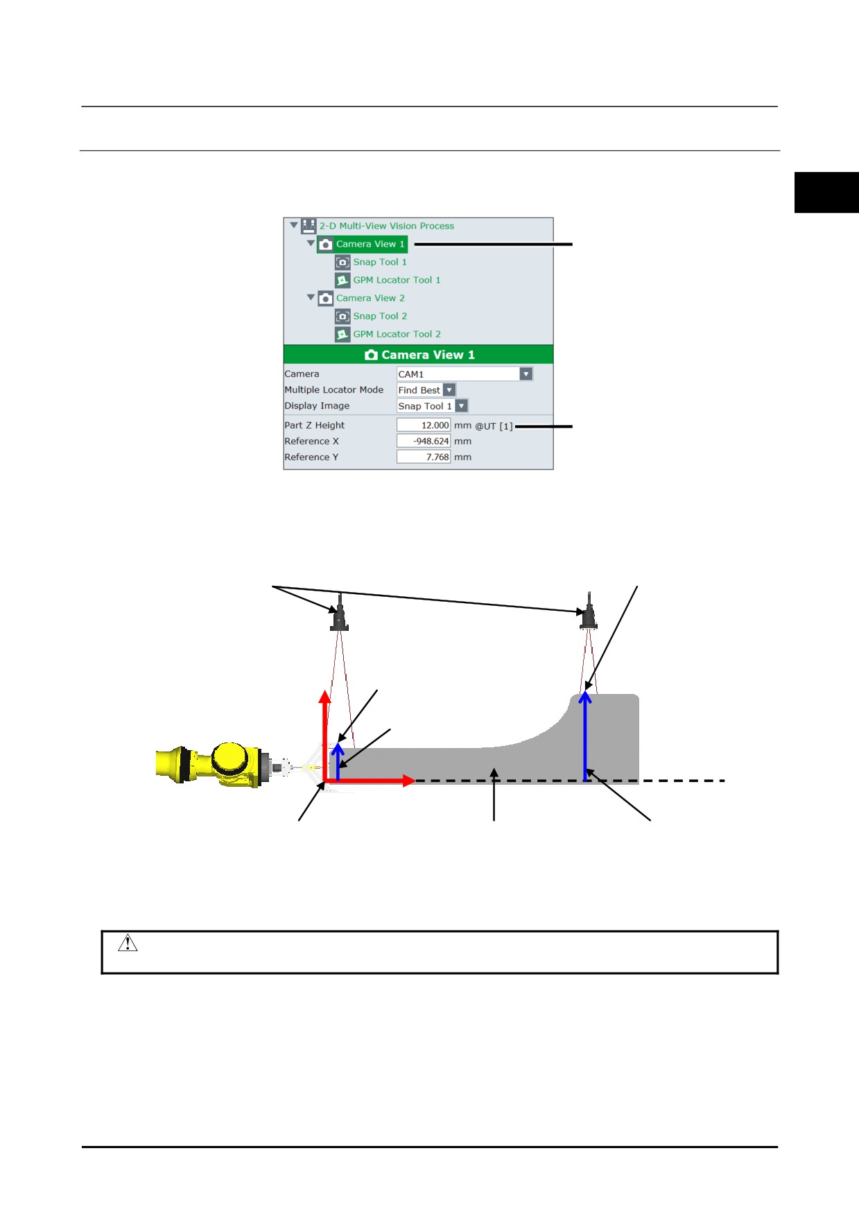
In the text box for [Part Z Height], enter the height of the detected part of the workpiece.
Enter the height of the detected part on the offset frame.
Enter an appropriate value for each camera view as shown in the figure below.
2nd measurement position
Camera
1st measurement position
Z
Part Z Height of camera view 1
X
Offset Frame
Workpiece
Part Z Height of camera view 2
Offset Frame and Part Z Height
4
Click [Snap] and snap the image, and click [Find] and detect [Camera View 1].
CAUTION
Do not move the workpiece until the reference position setting is complete.
5
Perform steps 1 to 4 for all camera views.
B-83914EN-2/01
75
2. 2D MULTI VIEW VISION PROCESS
Setup
6
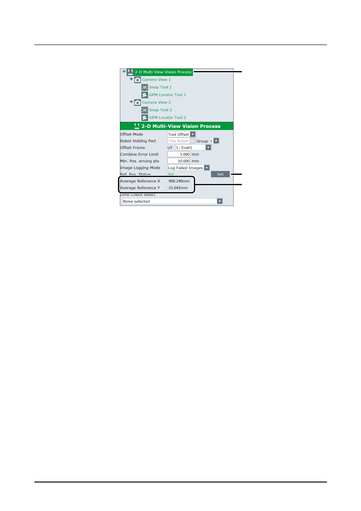
Select [2-D Multi-View Vision Process] from the tree view, and click [Find] to detect the workpiece.
6
7
8
7
Click the [Set] button for [Ref. Pos. Status]
8
Check that [Ref. Pos. Status] becomes [Set] and the values for [Average Reference X] and [Average
Reference Y] is displayed.
The values are the position of the center of gravity of the workpiece on the offset frame.
When all camera views can snap the workpiece without moving the robot, the detection of all
camera views can be performed by clicking once each on [Snap] and [Find] on the editing view of
[2-D Multi-View Vision Process]. In this case, it is not necessary to perform [Snap] and [Find] for
each camera view.
9
Click [Save] and click [End Edit].
10
Move the robot to the position to work to the workpiece (e.g. place it).
For an example, refer to the sample program in Setup Edition Subsection 2.4.4, "Robot Program
Creation and Teaching". P[3] in line 14 is the position to work to the workpiece. Record the
current robot position to P[3], and the reference position teaching is complete.
76
B-83914EN-2/01
Setup
2. 2D MULTI VIEW VISION PROCESS
2.4.4
Robot Program Creation and Teaching
The sample program is shown below. A vision process [A] is used.
Add the
"VOFFSET, VR"
instruction to the movement statement
2
1:
UFRAME_NUM=1 ;
2:
UTOOL_NUM=6 ;
3:
R[1:Notfound]=0
;
4:L P[1] 2000mm/sec FINE
;
5:
WAIT R[1] ;
6:
VISION RUN_FIND 'A' CAMERA_VIEW[1]
;
7:L P[2] 2000mm/sec FINE
;
8:
WAIT R[1] ;
9:
VISION RUN_FIND 'A' CAMERA_VIEW[2]
;
10: VISION GET_OFFSET 'A' VR[1] JMP LBL[100] ;
11:
;
12:
!Handling ;
13:L P[2] 2000mm/sec CNT100 VOFFSET,VR[1] Tool_Offset,PR[1]
;
14:L P[2] 500mm/sec FINE VOFFSET,VR[1]
;
15: CALL HAND_OPEN
;
16:L P[2] 2000mm/sec CNT100 VOFFSET,VR[1] Tool_Offset,PR[3]
;
17:
!Handling ;
18:
JMP_LBL[900] ;
19:
;
20: LBL[100] ;
21: R[1:Notfound]=1
;
22:
;
23: LBL[900] ;
Move the workpiece to the position to snap on line 4. Execute a “WAIT” instruction to remove the
vibration of the workpiece on line 5. Execute a camera view 1 of program “A” with the vision detection
instruction with the line 6. Move the workpiece to the position to snap at camera view 2 on line 7.
Obtain the offset data of the detected workpiece on line 10. Move the robot to the approach position to
place the workpiece on line 13. Move the robot to the position where the robot places the workpiece on
line 14. Move the robot to escape position after the workpiece is placed on line 16.
B-83914EN-2/01
77
2. 2D MULTI VIEW VISION PROCESS
Setup
2.4.5
Robot Compensation Operation Check
Check that a gripped workpiece by the robot can be detected and positioned precisely at a specified
location.
• Place the workpiece on the reference position, find it and check the handling accuracy. If the
accuracy of offset is low, set the reference position again.
• Move the workpiece without rotation, find it and check the handling accuracy. If the accuracy of
offset is good on the reference position, but it is low for non-rotated workpiece on the edge of the
field of view, it is possible that [Part Z Height] is not set properly. Check the [Part Z Height], refer
to Setup Edition Subsection 2.4.3.3, “Reference position setting”.
• Rotate the workpiece, find it and check the handling accuracy. If the accuracy of offset is good on
a workpiece without rotation, but it is low for rotated workpiece and lower for more rotated
workpiece, it is possible the offset frame or the calibration grid frame is not set properly. When
touch-up method is used to set up the frame, check the TCP setting is precise. Moreover, check the
offset frame and the calibration grid frame are set precisely. If there is necessary, retry the camera
calibration.
• Depending on robot motion, a workpiece may vibrate at snap position. Execute
“WAIT”
instruction to remove the vibration of a workpiece before the detection.
• Start with lower override of the robot to check that the logic of the program is correct. Next,
increase the override to check that the robot can operate continuously.
78
B-83914EN-2/01
Setup
3. DEPALLETIZING VISION PROCESS
3 DEPALLETIZING VISION PROCESS
The Depalletizing Vision Process is a vision process that performs compensation in the vertical direction
in addition to standard two-dimensional compensation. This function measures the height of the
3
workpieces based on the size of the workpiece image viewed by the camera. This section explains the
setup procedure for the Depalletizing Vision Process using the following two configurations as examples.
• "Fixed frame offset with fixed camera"
• "Fixed frame offset with robot-mounted camera"
For the each application, the basic program setting method is the same as for 2D Single-view Vision
Process. However, the Depalletizing Vision Process differs from the 2D Single-view Vision Process
about the method of reference position setting. Specifically, sets the relationship between the height of
workpieces and the size of the workpiece viewed by the camera. In this point, the Depalletizing Vision
Process differs from the 2D Single-view Vision Process.
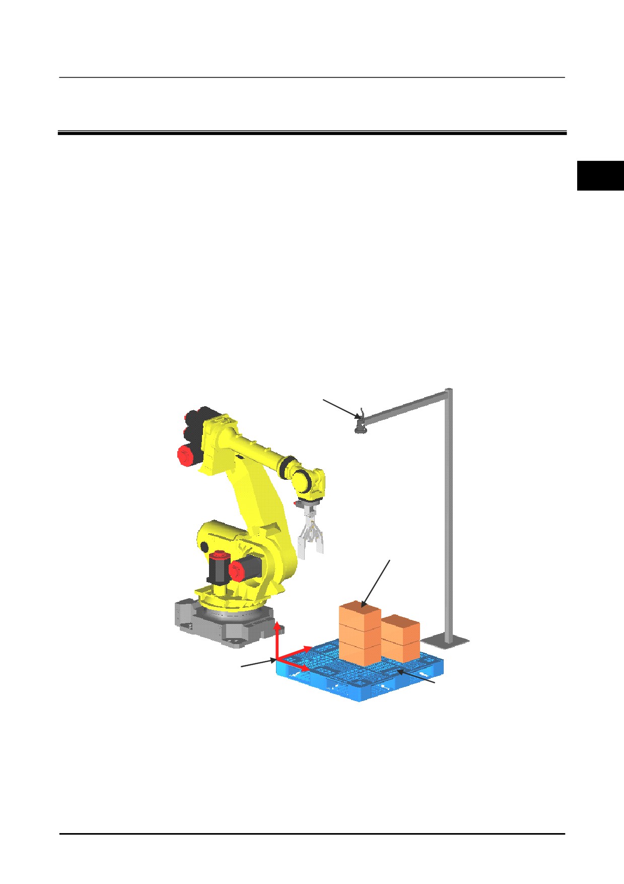
Fixed frame offset with fixed camera
An example of layout for "fixed frame offset with fixed camera" is given below.
Camera
Workpiece
Z
Y
Offset frame
X
Pallet
Example of layout for fixed frame offset with fixed camera
B-83914EN-2/01
79
3. DEPALLETIZING VISION PROCESS
Setup
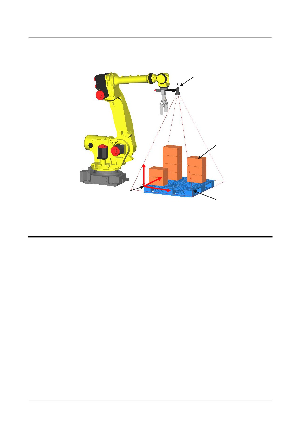
Fixed frame offset with robot-mounted camera
An example of layout for "fixed frame offset with robot-mounted camera" is given below.
Robot-mounted camera
Workpiece
Z
Y
X
Offset frame
Pallet
Example of layout for fixed frame offset with robot-mounted camera
3.1
FEATURES AND NOTES
Features
• This function performs compensation in the vertical
(Z) direction in addition to ordinary
two-dimensional compensation.
• The height (standard Z coordinate) of the workpieces are measured based on the size of the
workpiece image viewed by the camera.
• After an operation for picking up a workpiece from one location of the pallet is taught, a workpiece
can be picked up from an arbitrary row/column/stage.
• For robot-mounted cameras, the camera can be moved in the X, Y, and Z directions of the offset
frame in order to measure. This capability is provided because the current position of a robot is
considered in iRVision calculation processing when a workpiece position calculation is made.
Notes
• As with the 2-D Single-View Vision Process, the fixed frame offset is applied to the XY and R
directions. Therefore, it is assumed that each measurement plane is parallel to the XY plane of the
offset frame, and not tilted.
• The camera position for measurement is determined from the thickness of a workpiece and the
number of layers.
• When either a fixed camera or a robot-mounted camera is used, it is wanted that the optical axis of
the camera is normal to the XY plane of the offset frame. When the camera is attached in a
position that the optical axis of the camera is slantingly to the XY plane of the offset frame, it seems
that the shape of the workpiece is distorted depending on the place of a field of view. In this case,
it is possible that detection of the workpiece become difficult.
80
B-83914EN-2/01
Setup
3. DEPALLETIZING VISION PROCESS
• In order to absorb measurement errors in the App. Z Mode direction, it is recommended that you
prepare for the gripper a floating mechanism in the forwarding direction and a sensor for sensing
contact with the workpiece. For example, you can use a read switch of the cylinder and high speed
skipping to escape a robot hand when the hand and the workpiece contacts accidentally.
• The height of the workpieces are measured based on the size of the workpiece image viewed by the
camera. As a guideline, two workpieces found one layer apart should have a difference in size by
at least 5%.
3
• As the distance between the camera and workpiece increases, the precision in height measurement is
degraded. So, minimize this distance whenever possible.
• As the distance between the camera and workpieces increases, the precision in height measurement
is degraded. If a workpiece to be measured is located far away, the workpiece can be measured
again by approaching the workpiece if the camera is robot-mounted. In this case, the same vision
program can be used. This is because the current position of the robot is considered when a
workpiece position calculation is made.
• Ensure that the camera focuses on both the workpiece at the top and the workpiece at the bottom.
• Ensure that lighting is provided evenly to the workpiece at the top and the workpiece at the bottom
whenever possible. This is a key to stable workpiece detection and precise size measurement.
When a robot-mounted camera is used, it is recommended to install a ring light around the camera.
3.2
SETUP FOR FIXED FRAME OFFSET WITH FIXED
CAMERA
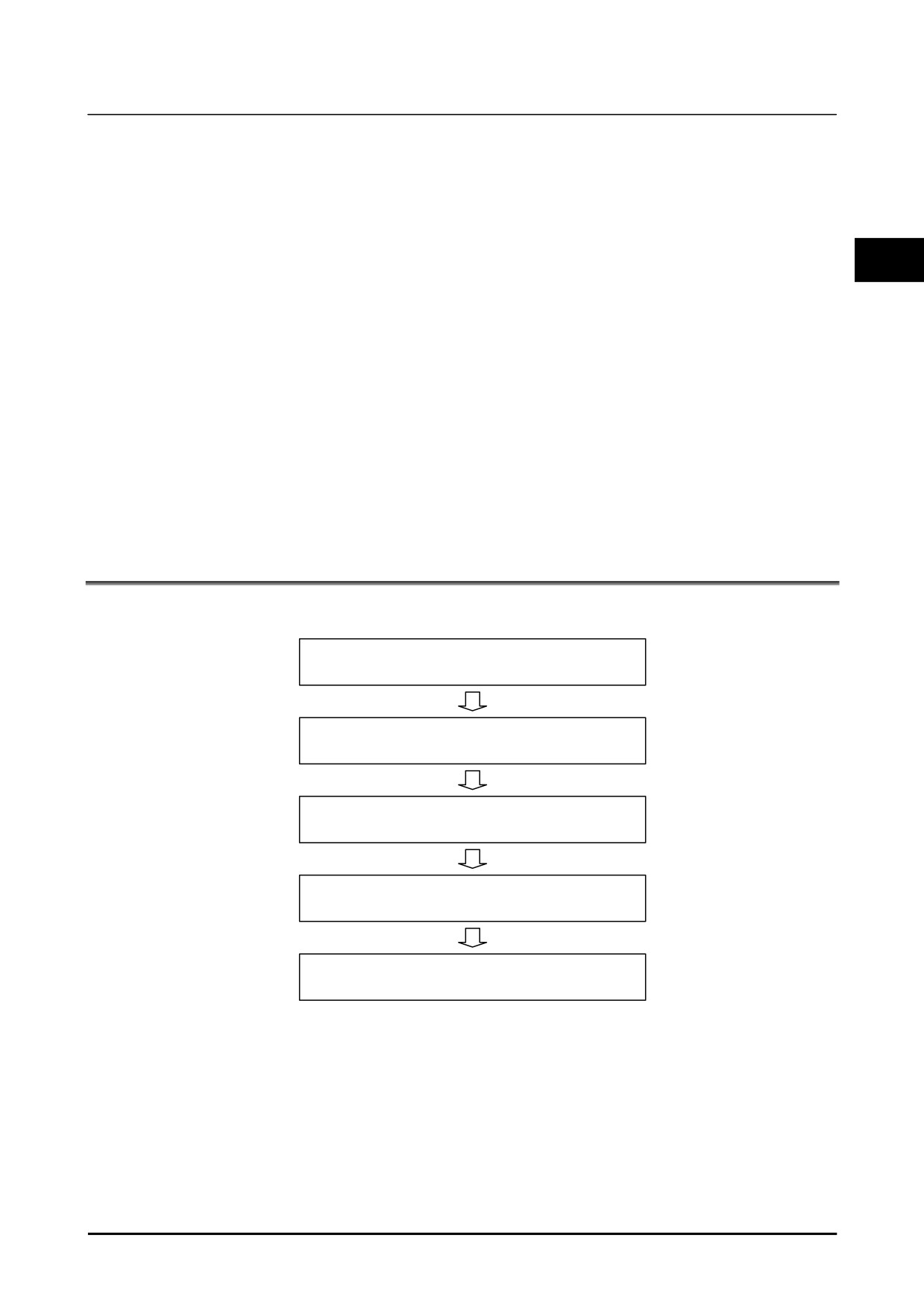
Use the following setup procedure for "fixed frame offset with fixed camera":
1.
Camera Data Creation and Teaching
2.
Offset frame setting
3.
Vision process creation and teaching
4.
Robot program creation and teaching
5.
Robot Compensation Operation Check
When starting up a robot system that uses iRVision, perform all of the tasks described above. When the
position of the fixed camera is shifted or cameras are exchanged, redo "1 Camera Data Creation and
Teaching". When a camera calibration has been already finished, in addition, a workpiece is changed or a
kind of workpiece is added, perform "3 Vision process creation and teaching". and "4 Robot program
creation and teaching".
B-83914EN-2/01
81
3. DEPALLETIZING VISION PROCESS
Setup
3.2.1
Camera Data Creation and Teaching
Create camera data and perform basic settings and calibration for the camera.
There are two kinds of methods for a camera calibration, those are Grid Pattern Calibration and
Robot-generated Grid Calibration.
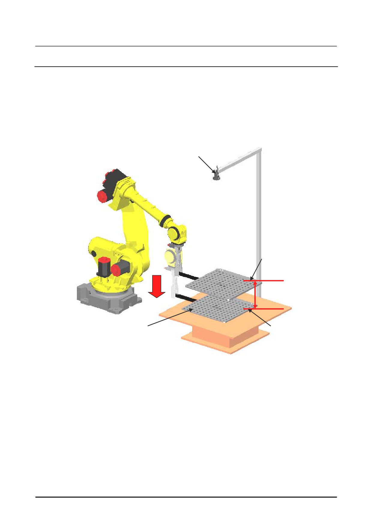
Grid Pattern Calibration
If you install a calibration grid on the gripper, make the vertical movement distance for when calibrating
with two planes something that will cover the upper and lower ends of workpiece distribution in the
pallet.
Camera
1st detection
Distance to cover
the upper and
lower ends of the
workpiece
Calibration grid
2nd detection
Installation example for Grid Pattern Calibration
For the setup method for Grid Pattern Calibration, refer to Know-how Edition Section 2.1, " GRID
PATTERN CALIBRATION WITH A FIXED CAMERA".
Robot-generated Grid Calibration
When you perform 2-D Single-View Vision Process, robot-generated grid calibration is suitable because
a field of view size tends to broaden. For the setup method for robot-generated grid calibration, refer to
Know-how Edition Section 2.3, "ROBOT-GENERATED GRID CALIBRATION".
82
B-83914EN-2/01
Setup
3. DEPALLETIZING VISION PROCESS
3.2.2
Offset Frame Setting
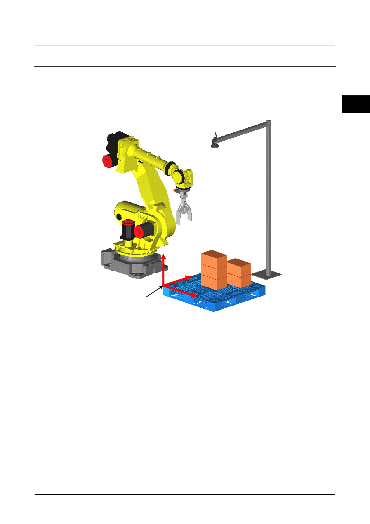
An offset frame is a coordinate system used for calculation of the offset data. A found position is
outputted as a position in the offset frame. In the fixed frame offset, the offset frame is set as a user
frame.
Set an offset frame so that the XY plane of the offset frame is parallel with the table plane on which the
3
workpiece is placed. Otherwise, the required compensation precision may not be obtained.
Z
Y
Offset frame
X
Offset frame setting
There are two methods to teach the offset frame, one is touch-up with the pointer tool, and another is the
Automatic Grid Frame Setting Function.
Touch-up
To teach with touch-up with a pointer tool, a pointer tool with correct TCP setting is required. In
general, set the TCP accurately at the tip of pointer tool attached to the robot hand. If the accuracy of
this TCP setting is low, the precision in handling of a workpiece by the robot is also degraded, especially
when the workpiece is rotated. Set a robot TCP in an arbitrary tool coordinate system. To reuse the
pointer TCP, the reproducibility of pointer installation is required. If the reproducibility of pointer
installation is not assured, a TCP needs to be set each time a pointer is installed. For details, refer to
Know-how Edition Subsection 1.1.1, “User frame setting”.
B-83914EN-2/01
83
3. DEPALLETIZING VISION PROCESS
Setup
Grid Frame Set
The Grid Frame Setting Function sets the calibration grid frame using a camera. Install a calibration
grid so that the XY plane of the calibration grid is parallel with the plane on which the workpiece is
placed, and perform the Grid Frame Setting Function. For details, refer to Know-how Edition Section
1.2, “FRAME SETTING WITH THE GRID FRAME SETTING FUNCTION”. A calibration grid is
used for a setup. Moreover, in the case of a fixed camera, prepare a camera for the Grid Frame Setting
Function separately. And perform the Grid Frame Setting Function using the camera attached to the
arbitrary positions of a robot's hand. In addition, the Grid Frame Setting Function is usable with 6-axis
robots only. The function cannot be used with 4-axis robots and 5-axis robots. When using 4-axis
robots or 5-axis robots, perform the touch-up to set a frame.
3.2.3
Vision Program Creation and Teaching
Perform vision process creation and teaching. Perform teaching about the locator tools and set the
reference position.
The basic program setting method is the same as for 2D Single-view Vision Process. Unlike 2D
Single-view Vision Process, Depalletizing Vision Process sets the relationship between the height of
workpieces and the size of the workpiece viewed by the camera.
Scale
100%
111%
Camera
Camera
Workpiece
Workpiec
Vision process creation and teaching
84
B-83914EN-2/01
Setup
3. DEPALLETIZING VISION PROCESS
3.2.3.1 Vision Process Creation
1
Create a vision process for [Depalletizing Vision Process].
For details on vision process creation, refer to Setup Edition Subsection 1.3.1.1, "Create" in the
"R-30iB Plus CONTROLLER iRVision OPERATOR’S MANUAL (Reference) B-83914EN".
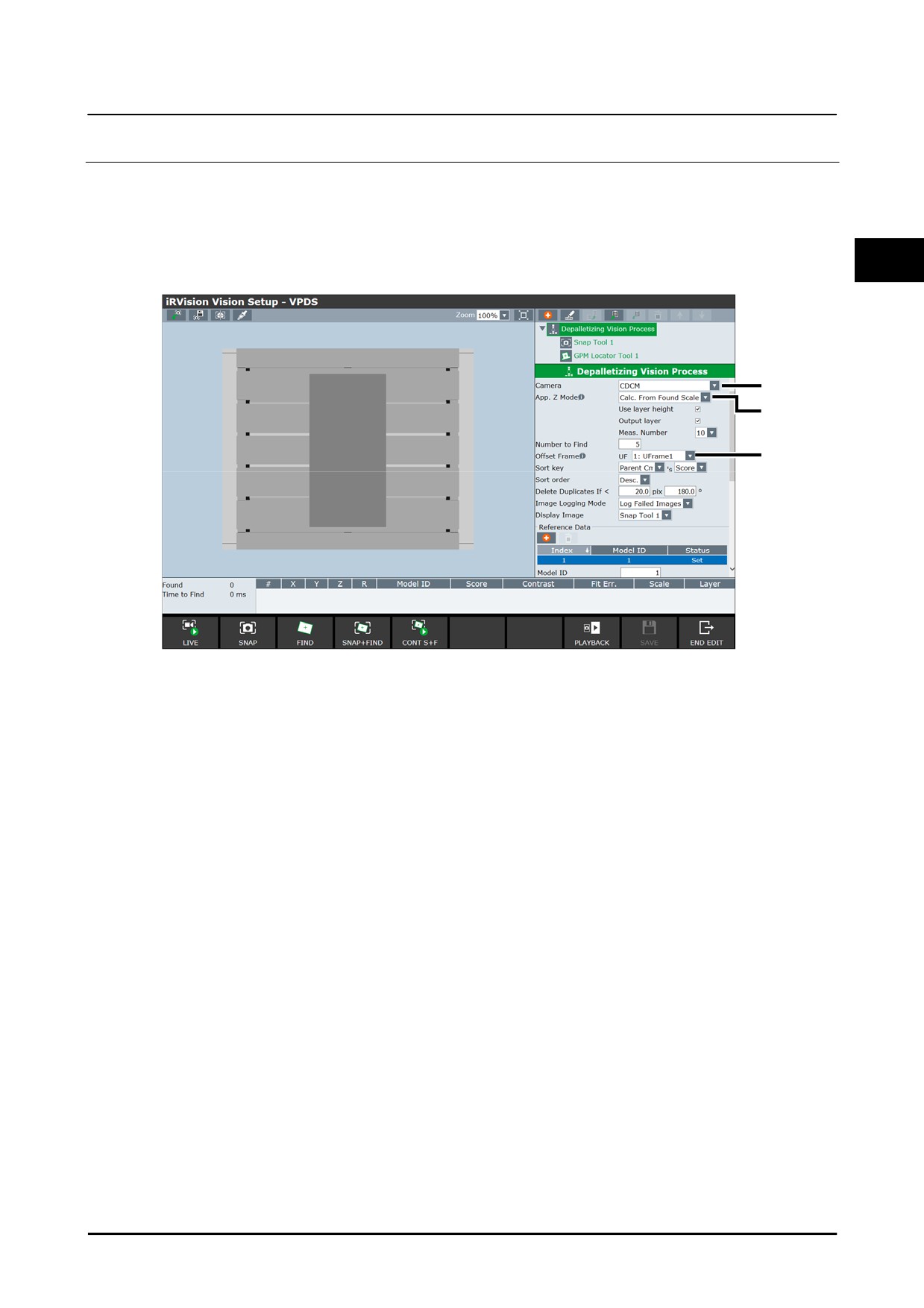
2
On the vision data list screen, if you select the created vision process and click [EDIT], the vision
data edit screen will appear.
3
3
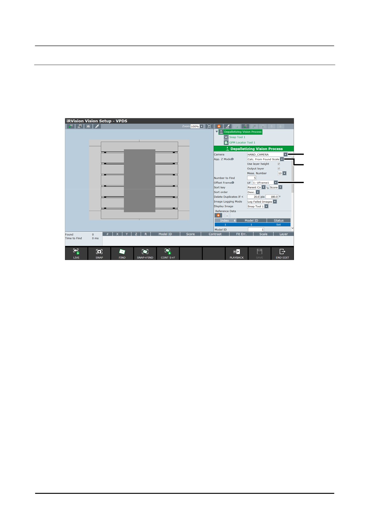
4
5
3
From the [Camera] drop-down box, select the camera data to be used.
Select the camera data specified in Setup Edition Subsection 3.2.1, " Camera Data Creation and
Teaching".
4
From the [App. Z Mode] drop-down box, select the operation.
5
From the [Offset Frame] drop-down box, select the user frame to set.
Select the frame number specified in Setup Edition Subsection 3.2.2, "Offset Frame Setting."
B-83914EN-2/01
85
3. DEPALLETIZING VISION PROCESS
Setup
3.2.3.2 Command tool teaching
1
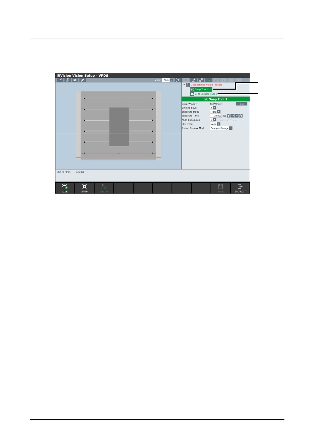
Put a workpiece in place.
2
3
2
Set up the snap tool.
The snap tool is a tool that snaps images that are used to teach and find models. Set the snap
conditions such as the snap range and exposure time. For details, refer to Setup Edition Section 4.1,
"SNAP TOOL" in "R-30iB Plus Controller iRVision OPERATOR’S MANUAL(Reference)
B-83914EN".
3
Select a locator tool in the tree view and teach the model to use for detection.
By default, the GPM Locator Tool is set as the locator tool. For details on the GPM Locator Tool
and other command tools, refer to Setup Edition Section 4, "COMMAND TOOLS" in "R-30iB Plus
Controller iRVision OPERATOR’S MANUAL(Reference) B-83914EN".
86
B-83914EN-2/01
Setup
3. DEPALLETIZING VISION PROCESS
3.2.3.3 Reference position setting
1
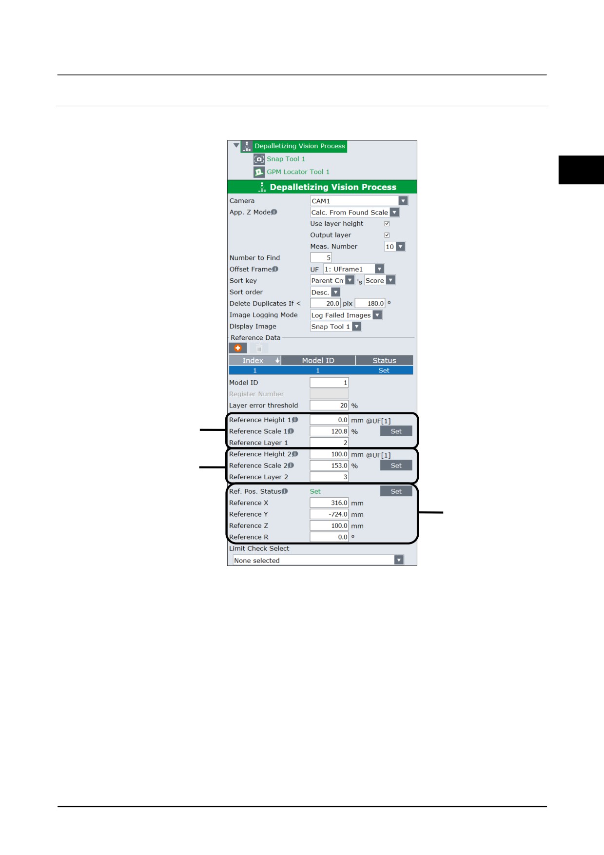
Select [Depalletizing Vision Process] in the tree view.
3
2, 3, 5
6, 7
9, 10
2
Enter the number of layers in the text box of [Reference Layer 1].
3
Measure the part height of a workpiece of [Reference Layer 1] as seen from the offset frame, and
enter it in the text box of [Reference Height 1].
Enter appropriate values as shown in the figure below.
B-83914EN-2/01
87
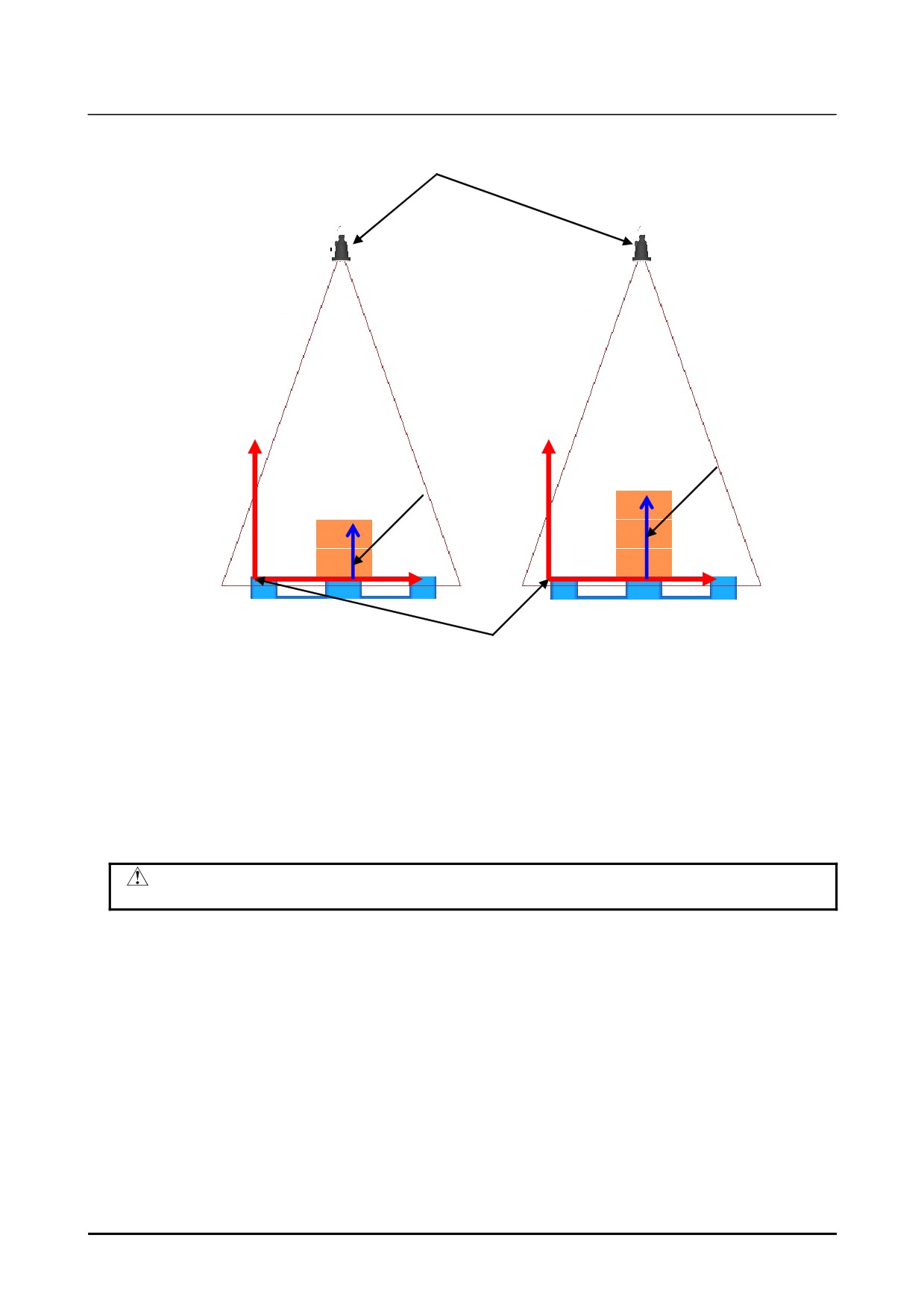
3. DEPALLETIZING VISION PROCESS
Setup
Camera
Z
Z
Reference height 2
Reference height 1
XY
XY
Offset Frame
Offset frame and part Z height
4
Click [SNAP] to snap the image, and click [FIND] to detect the workpiece for [Reference Layer 1].
5
Click the [Set] button for [Reference Scale 1].
A value will be displayed in [Reference Scale 1], and a reference scale will be set.
6
Stack N layers of workpieces, and enter the number of layers in the text box of [Reference Layer 2].
7
Carry out steps 3 to 6 for [Reference Layer 2].
8
Select [Depalletizing Vision Process] in the tree view, and click [FIND] to find the workpiece.
CAUTION
Do not move the workpiece until reference position setting is complete.
9
Click the [Set] button for [Ref. Pos. Status].
10
Check that [Ref. Pos. Status] has become [Set] and that there are values indicated in [Reference X],
[Reference Y], [Reference Z] and [Reference R].
The values are the position of the workpiece, as seen from the offset frame.
11 Jog the robot and move it to the position for performing work on the workpiece (e.g. gripping it).
For an example, refer to the sample program in Setup Edition Subsection 3.2.4, "Robot Program
Creation and Teaching". P[2] in line 11 is the position for performing work on the workpiece.
Record the current robot position to P[2], and reference position teaching is complete.
88
B-83914EN-2/01
Setup
3. DEPALLETIZING VISION PROCESS
3.2.4
Robot Program Creation and Teaching
In the sample program below, a vision process named "A" is used. For fixed frame offset, add the
"VOFFSET, VR" instruction as an operation statement.
1:
UFRAME_NUM=1 ;
3
2:
UTOOL_NUM=1 ;
3:
R[1:Notfound]=0
;
4:L P[1] 2000mm/sec FINE
;
5;
6:
VISION RUN_FIND 'A'
;
7:
VISION GET_OFFSET 'A' VR[1] JMP LBL[100] ;
8:
;
9:
!Handling ;
10:L P[2] 2000mm/sec CNT100 VOFFSET,VR[1] Tool_Offset,PR[2]
;
11:L P[2] 500mm/sec FINE VOFFSET,VR[1]
;
12: CALL HAND_CLOSE
;
13:L P[2] 2000mm/sec CNT100 VOFFSET,VR[1] Tool_Offset,PR[3]
;
14:
!Handling ;
15:
JMP_LBL[900] ;
16:
;
17: LBL[100] ;
18: R[1:Notfound]=1
;
20:
;
21: LBL[900] ;
Obtain the offset result of the detected workpiece on line 7. Move to the position above the workpiece on
line 10. Move to the grasp position on line 11. Move to the escape position after grasping the workpiece
on line 13.
3.2.5
Robot Compensation Operation Check
Check that a workpiece placed on the pallet can be detected and handled precisely.
Place the workpiece on the reference position, find it and check the handling accuracy. If the
accuracy of compensation is low, retry the reference position setting.
Move the workpiece without rotation, find it and check the handling accuracy. If the accuracy is
good for the reference position, but low for non-rotated workpiece on the edge of the field of view, it
is possible that Part Z Height is not set properly. Check the [Part Z Height], refer to Setup Edition
Subsection 3.2.3.3, “Reference position setting”.
Rotate the workpiece, find it and check the handling accuracy. If the accuracy is good for a moved
workpiece without rotation, but low for rotated workpiece and lower for more rotated workpiece, it
is possible that the offset frame or the calibration grid frame is not set properly. When performing
the touch-up with pointer tool to set up the frame, check the TCP setting is precise. Moreover,
check the offset frame and the calibration grid frame are set precisely, then retry the camera
calibration.
Stack several workpieces then move the robot to the top workpieces. Check that the robot moves
to the workpieces correctly. Remove the workpiece and repeat with the next workpiece. Start
with lower override of the robot to check that the logic of the program is correct. Next, increase
the override to check that the robot can operate continuously.
B-83914EN-2/01
89
3. DEPALLETIZING VISION PROCESS
Setup
3.3
SETUP FOR FIXED FRAME OFFSET WITH
ROBOT-MOUNTED CAMERA
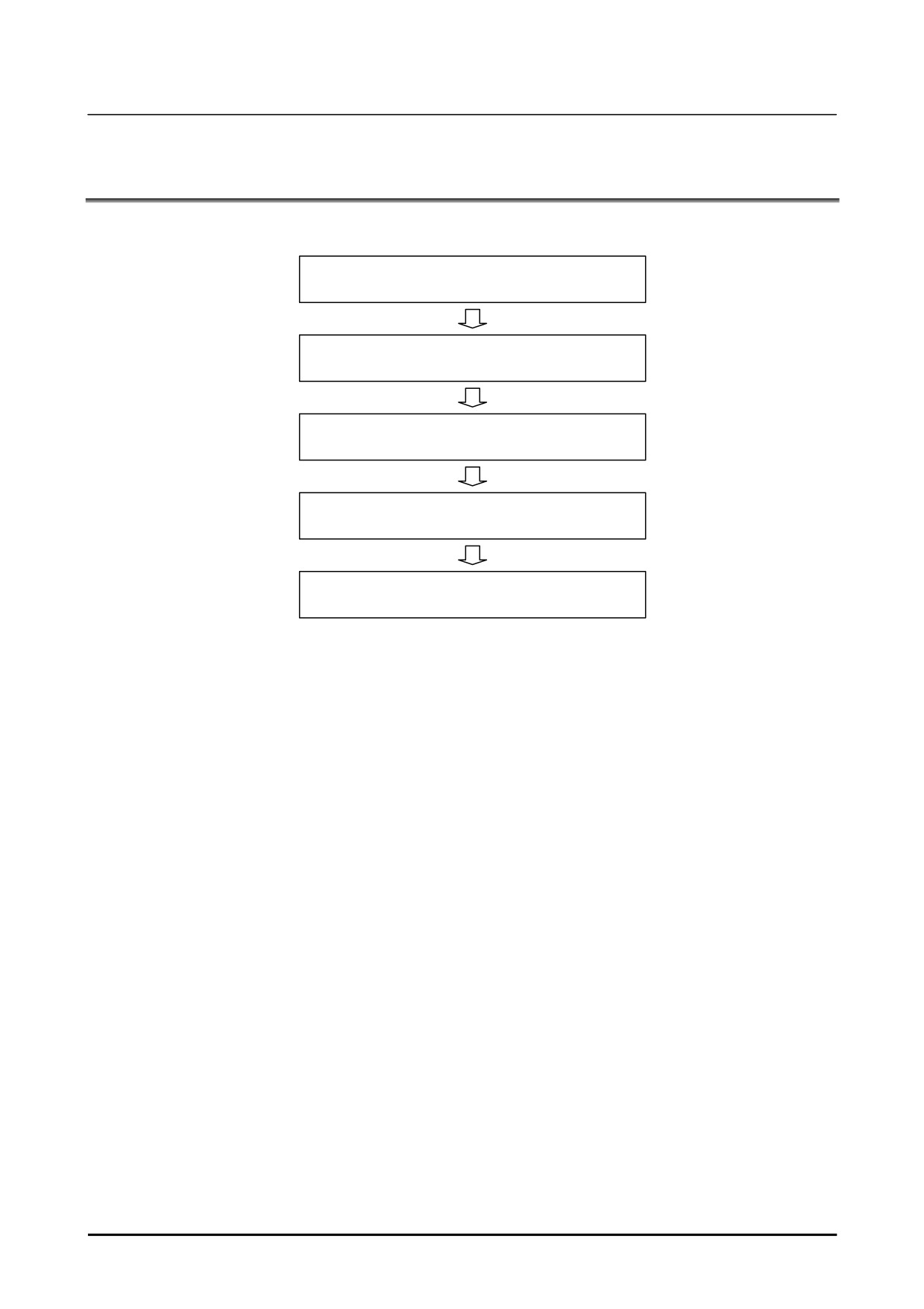
Use the following setup procedure:
1.
Camera Data Creation and Teaching
2.
Offset frame setting
3.
Vision process creation and teaching
4.
Robot program creation and teaching
5.
Robot Compensation Operation Check
When starting up a robot system that uses iRVision, perform all of the tasks described above. When the
position of the camera on the robot mechanical interface frame (the robot face plane) is shifted or cameras
are exchanged, redo "1 Camera Data Creation and Teaching". When a camera calibration has been
already finished, in addition, a workpiece is changed or a kind of workpiece is added, perform "3 Vision
process creation and teaching." and "4 Robot program creation and teaching."
90
B-83914EN-2/01
Setup
3. DEPALLETIZING VISION PROCESS
3.3.1
Camera Data Creation and Teaching
Create camera data and perform basic settings and calibration for the camera.
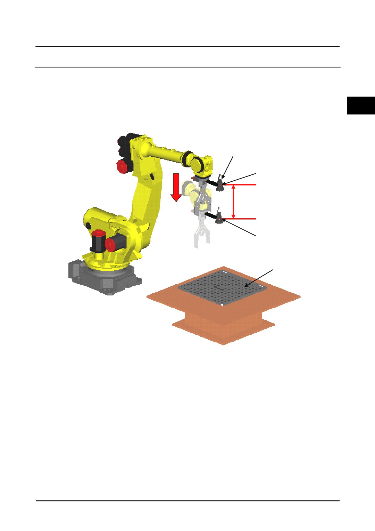
Use Grid Pattern Calibration for a robot-mounted camera calibration. Robot-Generated Grid Calibration
cannot be used for robot-mounted cameras. If you install a calibration grid on the gripper, make the
3
vertical movement distance for when calibrating with two planes something that will cover the upper and
lower ends of workpiece distribution in the pallet.
Camera
1st detection
Distance to cover the upper and
lower ends of the workpiece
2nd detection
Calibration grid
Installation example for Grid Pattern Calibration of robot-mounted camera
For the setup method for Grid Pattern Calibration, refer to Know-how Edition Section 2.2, "GRID
PATTERN CALIBRATION WITH A ROBOT-MOUNTED CAMERA".
B-83914EN-2/01
91
3. DEPALLETIZING VISION PROCESS
Setup
3.3.2
Offset Frame Setting
An offset frame is a coordinate system used for calculation of the offset data. A found position is
outputted as a position in the offset frame. In the fixed frame offset, the offset frame is set as a user
frame.
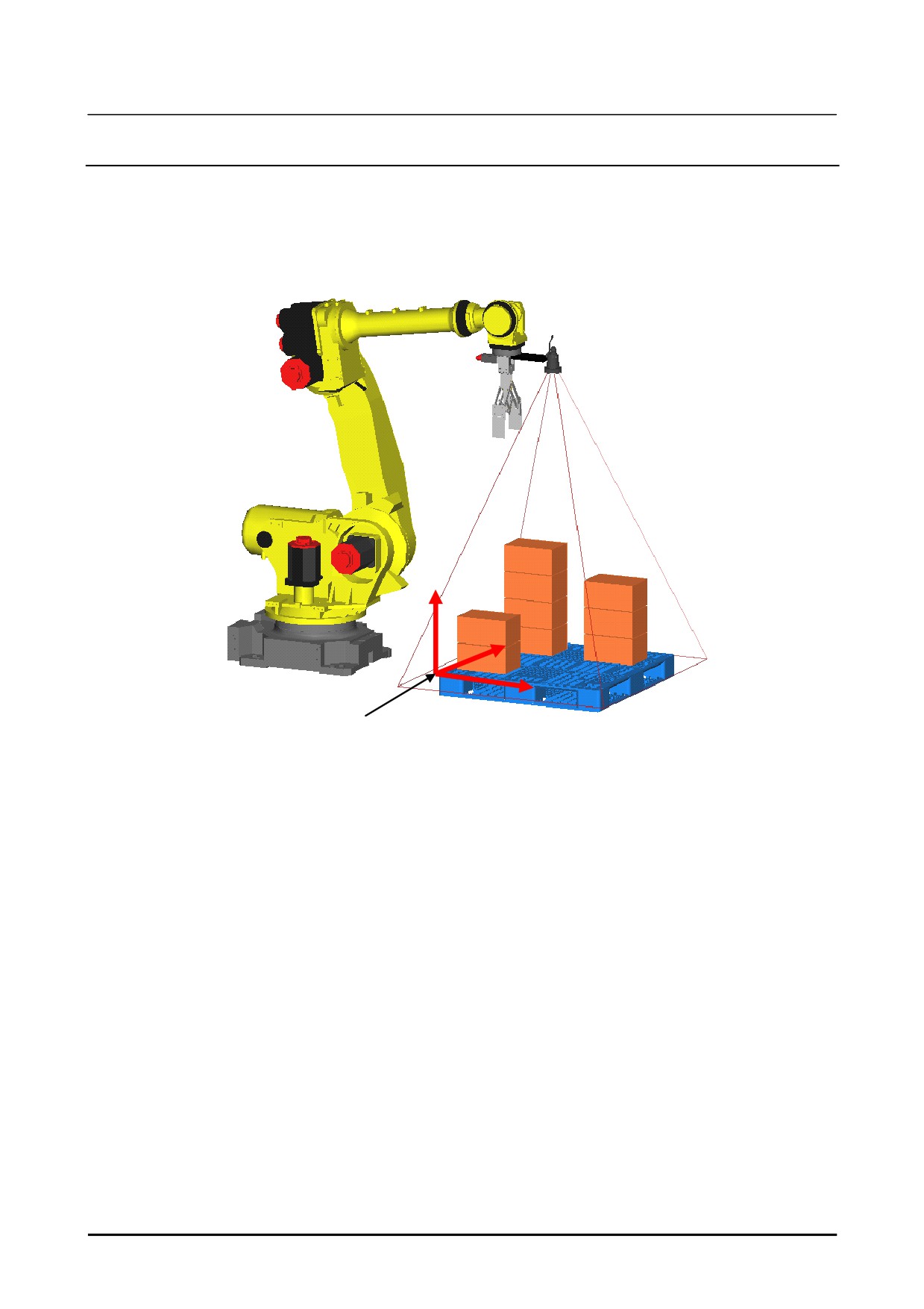
Set an offset frame so that the XY plane of the user frame is parallel with the table plane on which a
workpiece is placed. Otherwise, the required compensation precision may not be obtained.
Z
Y
X
Offset frame
Offset frame setting
There are two methods to teach the offset frame, one is touch-up with the pointer tool, and another is the
Automatic Grid Frame Setting Function.
Touch-up
To set up by touch-up, a pointer tool with a taught TCP is required. In general, set the TCP accurately
on the pointer installed on the robot gripper. If the accuracy of this TCP setting is low, the precision in
handling of a workpiece by the robot is also degraded, especially when the workpiece is rotated. Set a
robot TCP in an arbitrary tool coordinate system. To reuse the pointer TCP, the reproducibility of
pointer installation is required. If the reproducibility of pointer installation is not assured, a TCP needs
to be set each time a pointer is installed. For details, refer to Know-how Edition Subsection 1.1.1, “User
frame setting”.
Grid Frame Setting Function
The Grid Frame Setting Function sets the calibration grid frame using a camera. Install a calibration
grid so that the XY plane of the calibration grid is parallel with the plane on which the workpiece is
placed, and perform the Grid Frame Setting Function. For details, refer to Know-how Edition Section
1.2, “FRAME SETTING WITH THE GRID FRAME SETTING FUNCTION”. A calibration grid is
used for a setup. In the case of a robot-mounted camera, the Grid Frame Setting Function can be
performed with the camera currently used. When there is not sufficient space to perform Grid Frame
Setting Function with the camera currently used, prepare another robot-mounted camera and Grid Frame
Setting Function can be performed. In addition, the Grid Frame Setting Function is usable with 6-axis
92
B-83914EN-2/01
Setup
3. DEPALLETIZING VISION PROCESS
robots only. The function cannot be used with 4-axis robots and 5-axis robots. When using a 4-axis
robots or 5-axis robots, perform the touch-up to set a frame.
3.3.3
Vision Process Creation and Teaching
Perform vision process creation and teaching. Perform teaching about the locator tools and set the
3
reference position.
Unlike 2D Single-view Vision Process, Depalletizing Vision Process sets the relationship between the
height of workpieces and the size of the workpiece viewed by the camera.
Scale
111%
100%
Camera
Camera
Workpiece
Workpiece
Vision process creation and teaching
B-83914EN-2/01
93
3. DEPALLETIZING VISION PROCESS
Setup
3.3.3.1 Vision Process Creation
1
Create a vision process for [Depalletizing Vision Process].
For details on vision process creation, refer to Setup Edition Subsection 1.3.1.1, "Create" in "R-30iB
Plus Controller iRVision OPERATOR’S MANUAL(Reference) B-83914EN".
2
On the vision data list screen, if you select the created vision process and click [EDIT], the vision
data edit screen will appear.
3
4
5
3
From the [Camera] drop-down box, select the camera data to be used.
For details, refer to Setup Edition Subsection 3.3.1, "Camera Data Creation and Teaching".
4
From the [App. Z Mode] drop-down box, select the operation.
5
From the [Offset Frame] drop-down box, select the user frame to set.
Select the frame number specified in Setup Edition Subsection 3.2.2, "Offset Frame Setting".
94
B-83914EN-2/01
Setup
3. DEPALLETIZING VISION PROCESS
3.3.3.2 Command tool teaching
1
Put a workpiece in place.
2
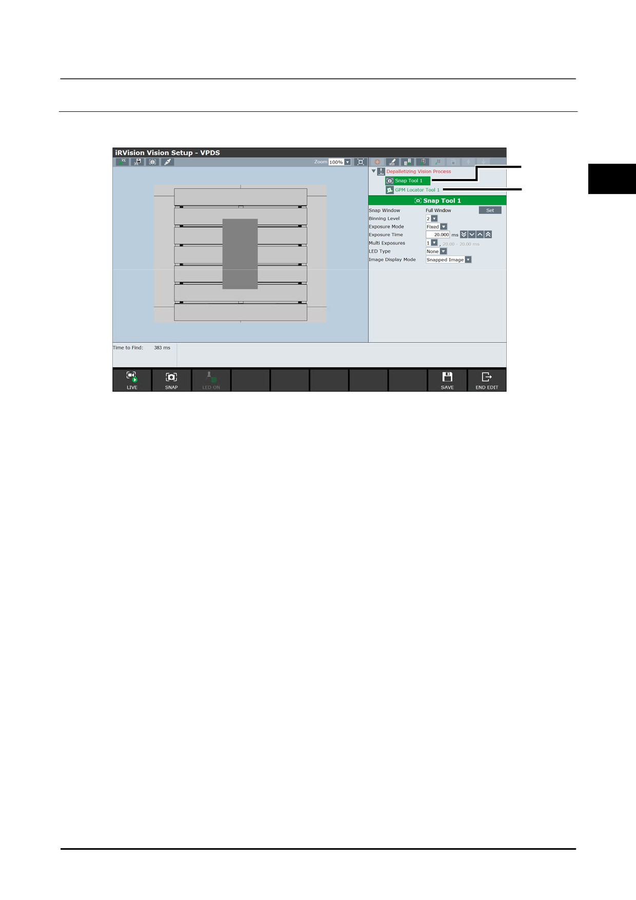
3
3
2
Set up the snap tool.
The snap tool is a tool that snaps images that are used to teach and find models. Set the snap
conditions such as the snap range and exposure time. For details, refer to Setup Edition Section 4.1,
"SNAP TOOL" in "R-30iB Plus Controller iRVision OPERATOR’S MANUAL(Reference)
B-83914EN".
3
Select a locator tool in the tree view and teach the model to use for detection. By default, the GPM
Locator Tool is set as the locator tool. For details on the GPM Locator Tool and other command
tools, refer to Setup Edition Section 4, "COMMAND TOOLS" in "R-30iB Plus Controller iRVision
OPERATOR’S MANUAL(Reference) B-83914EN".
B-83914EN-2/01
95
3. DEPALLETIZING VISION PROCESS
Setup
3.3.3.3 Reference position setting
1
Select [Depalletizing Vision Process] in the tree view.
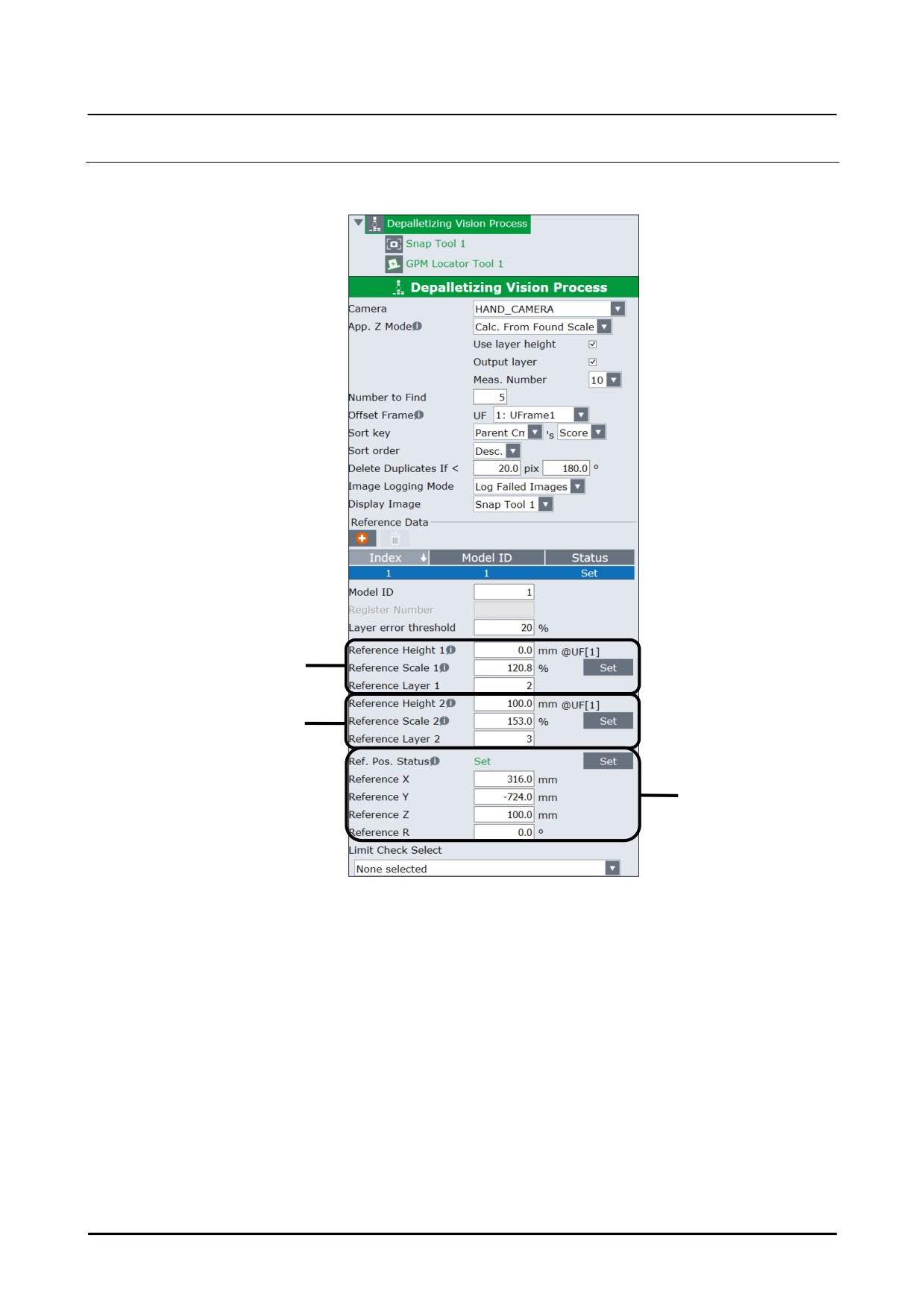
2, 3, 5
6, 7
9, 10
2
Enter the number of layers in the text box of [Reference Layer 1].
3
Measure the part height of a workpiece of [Reference Layer 1] as seen from the offset frame, and
enter it in the [Reference Height 1] text box.
Enter appropriate values as shown in the figure below.
96
B-83914EN-2/01
Setup
3. DEPALLETIZING VISION PROCESS
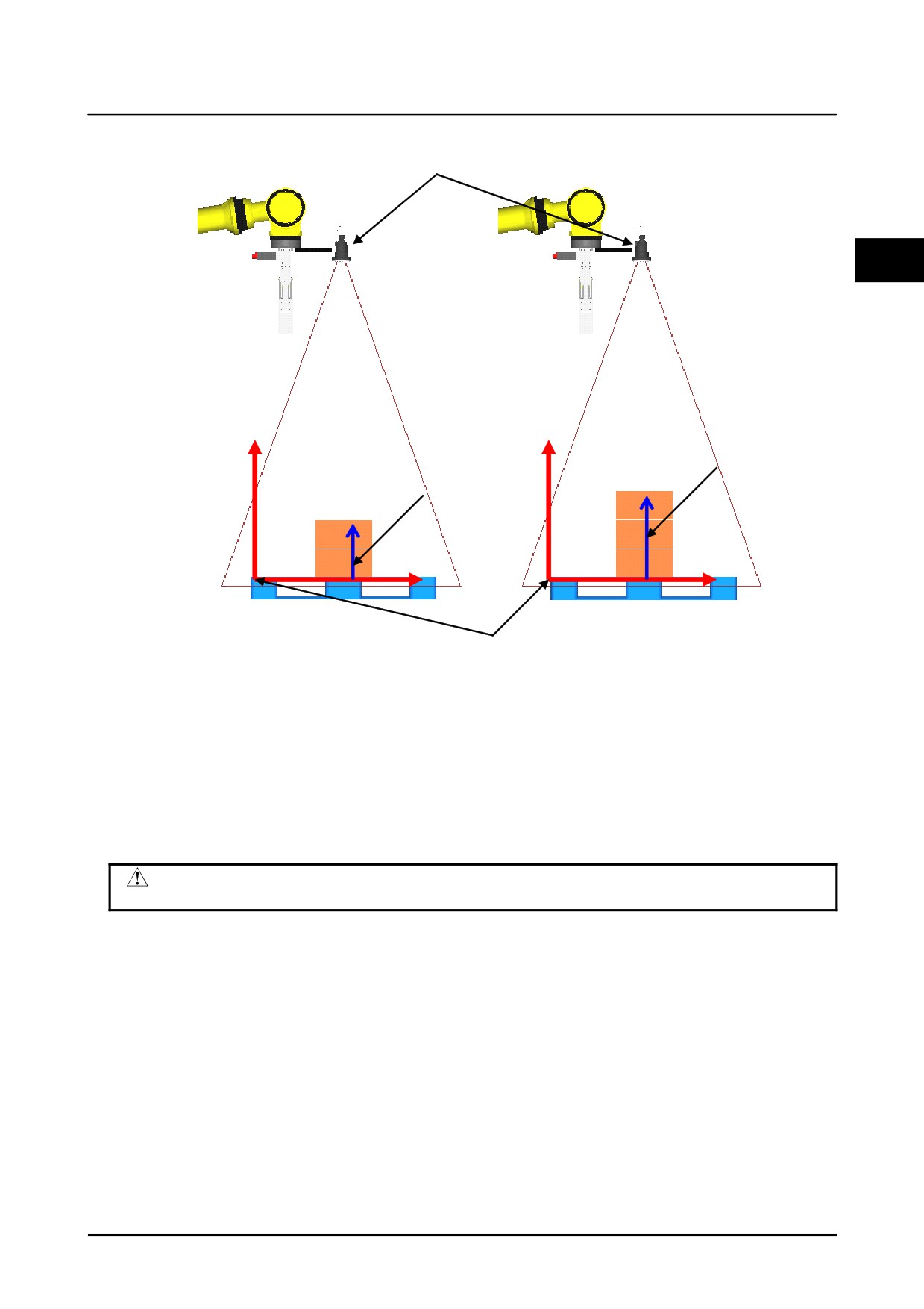
Camera
3
Z
Z
Reference Height 2
Reference Height 1
XY
XY
Offset Frame
Offset frame and part Z height
4
Click [SNAP] to snap the image, and click [FIND] to detect the workpiece for [Reference Layer 1].
5
Click the [Set] button for [Reference Scale 1].
A value will be displayed in [Reference Scale 1], and a reference scale will be set.
6
Stack N layers of workpieces, and enter the number of layers in the [Reference Layer 2] text box.
7
Carry out steps 3 to 6 for [Reference Layer 2].
8
Select [Depalletizing Vision Process] in the tree view, and click [FIND] to find the workpiece.
CAUTION
Do not move the workpiece until reference position setting is complete.
9
Click the [Set] button for [Ref. Pos. Status].
10
Check that [Ref. Pos. Status] has become [Set] and that there are values indicated in [Reference X],
[Reference Y], [Reference Z] and [Reference R].
The values are the position of the workpiece, as seen from the offset frame.
11 Jog the robot and move it to the position for performing work on the workpiece (e.g. gripping it).
For an example, refer to the sample program in Setup Edition Subsection 3.3.4, "Robot Program
Creation and Teaching". P[2] in line 11 is the position for performing work on the workpiece.
Record the current robot position to P[2], and reference position teaching is complete.
B-83914EN-2/01
97
3. DEPALLETIZING VISION PROCESS
Setup
3.3.4
Robot Program Creation and Teaching
In the sample program below, a vision process named "A" is used. A robot-mounted camera is used,
and the "OFFSET" instruction is used on line 4 to shift the camera image snap position on the pallet.
Shifting the image snap robot position by adding a constant value to the value of PR[1] simplifies
programming. For fixed frame offset, add the "VOFFSET,VR" instruction as an operation statement.
1:
UFRAME_NUM=1 ;
2:
UTOOL_NUM=1 ;
3:
R[1:Notfound]=0
;
4:L P[1] 2000mm/sec FINE Offset,PR[1]
;
5:
WAIT R[1] ;
6:
VISION RUN_FIND 'A'
;
7:
VISION GET_OFFSET 'A' VR[1] JMP LBL[100] ;
8:
;
9:
!Handling ;
10:L P[2] 2000mm/sec CNT100 VOFFSET,VR[1] Tool_Offset,PR[2]
;
11:L P[2] 500mm/sec FINE VOFFSET,VR[1]
;
12: CALL HAND_CLOSE
;
13:L P[2] 2000mm/sec CNT100 VOFFSET,VR[1] Tool_Offset,PR[3]
;
14:
!Handling ;
15:
JMP_LBL[900] ;
16:
;
17: LBL[100] ;
18: R[1:Notfound]=1
;
19:
;
20: LBL[900] ;
Move to camera position to snap on line 4. Execute “WAIT” instruction to remove the possible
vibration of a camera on line 5. Execute process ”A” with the vision detection instruction on line 6.
Obtain the measurement result of the detected workpiece on line 7. Move to the approach position
above the workpiece on line10. Move to the grasp position on line11. Move to the escape position
after grasping the workpiece on line13.
98
B-83914EN-2/01
Setup
3. DEPALLETIZING VISION PROCESS
3.3.5
Robot Compensation Operation Check
Check that a workpiece placed on the pallet can be detected and handled precisely.
• Place the workpiece on the reference position, find it and check the handling accuracy. If the
accuracy of compensation is low, retry the reference position setting.
• Move the workpiece without rotation, find it and check the handling accuracy. If the accuracy is
3
good for reference position, but low for non-rotated workpiece on the edge of the field of view, it is
possible that Part Z Height is not set properly. Check the Part Z Height, refer to Setup Edition
Subsection 3.3.3.3, “ Reference position setting”
• Rotate the workpiece, find it and check the handling accuracy. If the accuracy is good for a moved
workpiece without rotation, but low for rotated workpiece and lower for more rotated workpiece, it
is possible that the offset frame or the calibration grid frame is not set properly. Check the TCP
setting is precise. Moreover, check the offset frame and the calibration grid frame are set precisely,
then, retry the camera calibration.
• Depending on robot motion, a camera may vibrate at snap position. Execute “WAIT” instruction to
remove the possible vibration of a workpiece before the “VISION RUN_FIND”.
• Stack several workpieces then move the robot to the top workpieces. When performing the
touch-up with pointer tool to set up the frame, check that the robot moves to the workpieces
correctly. Remove the workpiece and repeat with the next workpiece. Start with lower override
of the robot to check that the logic of the program is correct. Next, increase the override to check
that the robot can operate continuously.
B-83914EN-2/01
99
4. 3D TRI-VIEW VISION PROCESS
Setup
4
3D TRI-VIEW VISION PROCESS
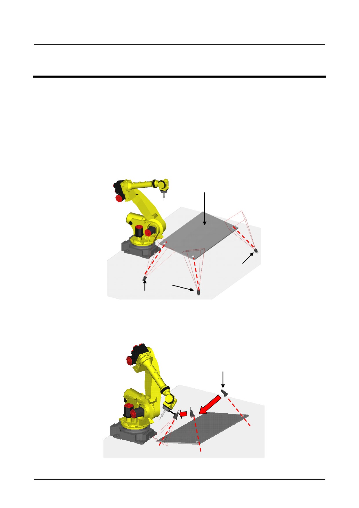
The 3D Tri-View Vision Process is the function for making three-dimensional compensation by
measuring three detection targets of a large workpiece such as a car body.
This chapter describes the setup procedure for 3D Tri-View Vision Process by using the following two
application examples:
• Fixed frame offset with fixed camera
• Fixed frame offset with robot mounted camera
Fixed frame offset with fixed camera
An example of layout for ‘fixed frame offset with fixed camera’ is given below. Three points of a
workpiece are measured by three fixed cameras.
Workpiece
Camera
Camera
Camera
Fixed frame offset with robot mounted camera
An example of layout for ‘fixed frame offset with robot mounted camera’ is given below. Three points
of a workpiece are measured by moving a camera.
Camera
100
B-83914EN-2/01
Setup
4. 3D TRI-VIEW VISION PROCESS
4.1
FEATURES AND NOTES
Features
• Three-dimensional compensation is made by measuring three points on a large workpiece that has
the potential to move in three dimensions.
• Compensation is applied to all of six degrees of freedom for parallel displacement (X, Y, Z) and
rotation (W, P, R) of the workpiece.
• The number of measurement points (number of camera views) is three and cannot be changed.
4
• The 3D Tri-View Vision Process has ‘camera views’ in a program as two-dimensional compensation
based on multiple cameras. There are three camera views for measuring a total of three detection
targets.
• During detection, a total of three view lines (one for each camera view) are measured. A triangle
that takes the three detection targets as vertices and has known shape is applied to the three view
lines to identify the position of each detection target on the corresponding view line and obtain the
three-dimensional position and posture of the workpiece.
• Only fixed frame offset can be performed.
• Both a fixed camera and a robot mounted camera can be used.
• A robot mounted camera can measure a detection target while moving the position of the robot to the
three locations. This capability is provided because the current position of a robot is considered in
iRVision calculation processing when a target position calculation is made.
Notes
• The following conditions must be met when determining detection targets.
(For a car body, the
reference holes are suitable).
-
The exact relative position or distance between the three detection targets must be known. It
should be obtained from a drawing.
-
The relative relation between the positions of the three detection targets and the work positions
does not change individually.
-
Three detection targets can be set so that the whole workpiece can be covered.
-
The triangle having the three detection targets as its vertices is not too shallow.
-
The shapes of the detection targets are constant.
-
There is no portion having a similar shape near the detection targets.
• Determine the camera view so that the detection targets do not fall outside the camera view even
when they deviate at the maximum. However, if the camera field of view is too wide, the required
compensation accuracy may not be obtained.
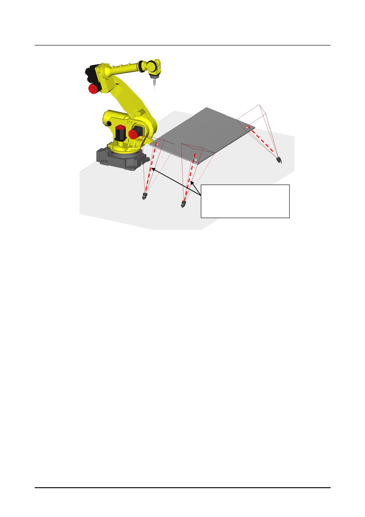
• When the detection targets are detected, three view lines are measured. The cameras need to be
placed so that any pair of view lines is not parallel and any angle formed by tow view lines is large
to some extent (if possible, 60 degrees or more). If the angle formed by view lines is tool small,
the required precision may not be obtained.
B-83914EN-2/01
101
4. 3D TRI-VIEW VISION PROCESS
Setup
In this figure, these two lines are
substantially parallel and the angle
formed by view lines is small.
Do not select this placement.
Angle formed by view lines
Preparation for drawings etc. about a workpiece
The 3D Tri-View Vision Process uses the distance between detection targets for calculation, so it is
necessary to input the coordinates of detection targets of the workpiece in an arbitrary coordinate system.
The coordinate system is not important because the relative distance between the targets is what is
important. Typically the coordinates of the targets in the workpiece come from a drawing.
102
B-83914EN-2/01