FANUC R-30iB Plus CONTROLLER, iRVision 2D Camera Application. OPERATOR'S MANUAL - page 2
2. ABOUT VISION SYSTEM
Introduction
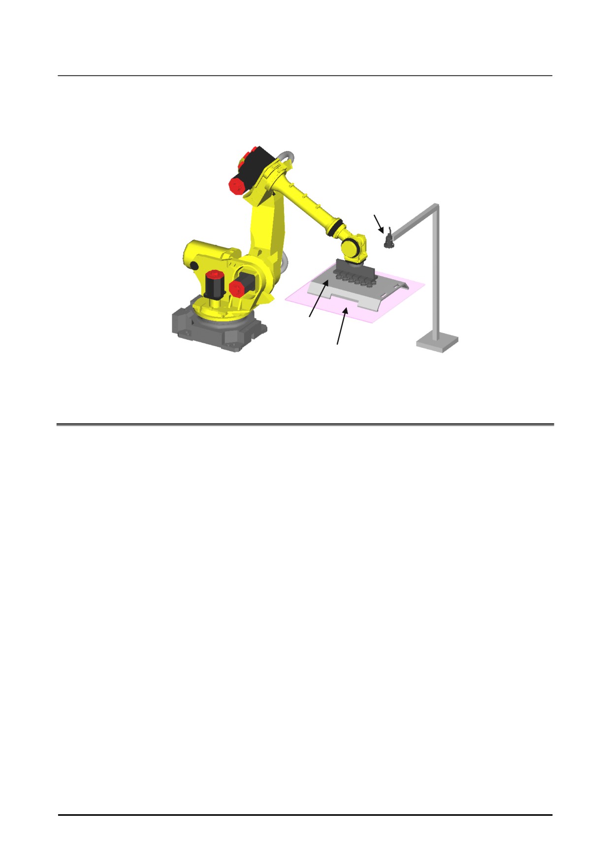
Tool offset
Detect the workpiece which gripped by the robot, and offset the robot positions so that the robot works
(for example, the robot places up the workpiece.) in correct.
Camera
Workpicec
Plane on which a workpicec moves
Tool Offset
2.5
CALCULATION OF THE OFFSET DATA
In this subsection, the calculation method of the offset data is explained.
Reference position and actual position
The offset data is calculated from the position of the workpiece of when teaching the robot program and
the position of the current workpiece. The position of the workpiece of when the robot program was
taught is called as the reference position, and the current position of workpiece is called the actual
position. iRVision measures the reference position when the robot program is taught, and stores it
internally. The operation of teaching the reference position to iRVision is called reference position
setting.
Offset data
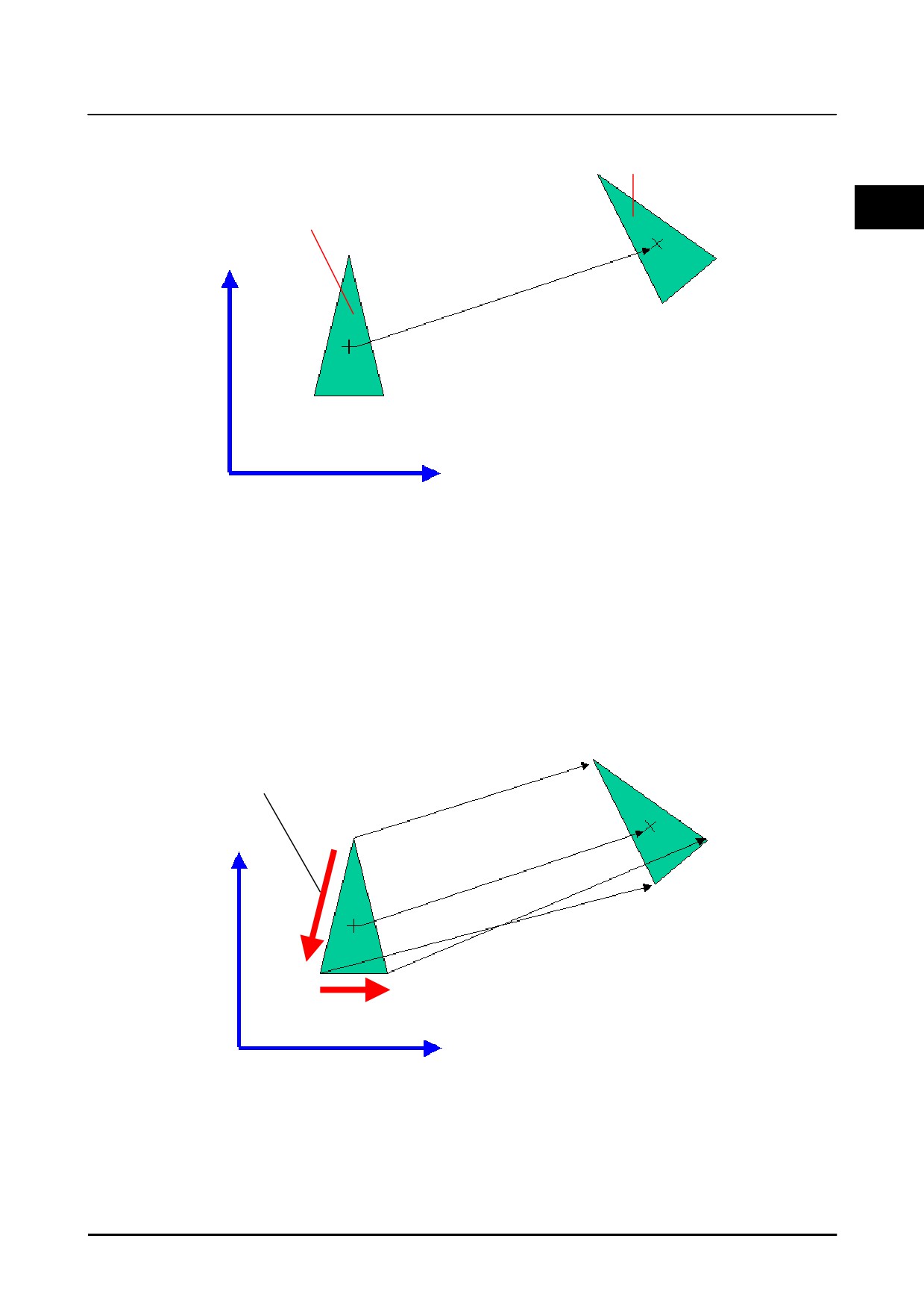
In the case of the following figure, the position of “+” mark is a found position of a workpiece. If a
robot approaches only to the position of “+” mark, the offset data can be calculated by subtracting the
value of the actual position and the reference position. When the calculation of the offset data is
subtraction, it is easy to understand, however there are also limitations.
10
B-83914EN-2/01
Introduction
2. ABOUT VISION SYSTEM
Workpiece at actual position
2
Workpiece at reference position
Offset frame
Offset calculation by subtraction
In the following figure, the position M is the reference position and the position m is the actual position.
A workpiece is placed on the reference position and the robot traces from the position A to the position B
and C. When the workpiece is placed at the actual position, to trace the -- a, b and c --, each positions
information are required. However, the movement of (a − A), (b − B) and (c − C) differ from the
movement of the found position (m − M). So, it is necessary to calculate the offset data of a, b and c
individually.
a
Motion path of a robot
m
A
c
b
M
B
C
Offset frame
Position Information and movement amount
B-83914EN-2/01
11
2. ABOUT VISION SYSTEM
Introduction
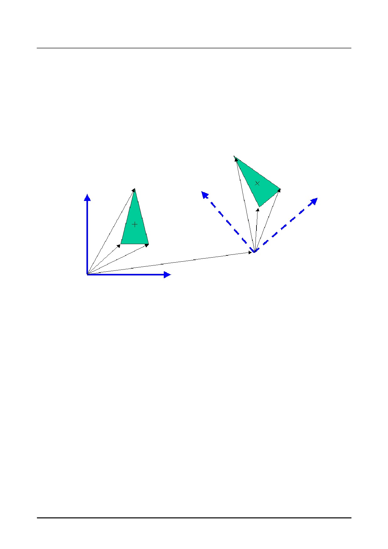
iRVision uses an offset frame, it is unnecessary to calculate the each position individually. In the
following figure, iRVision moves the offset frame to a new position. The position of the workpiece
relative to the offset frame is the same as the position of the workpiece at the reference position by
moving the offset frame, it becomes unnecessary to calculate the offset data for each point individually,
and teaching becomes easy. iRVision outputs the movement of offset frame as the offset data. Since
the offset data is the movement of the user frame, it is not the physically movement of the workpiece.
Moreover, the offset data does not become an intuitive value in many cases. Normally, when the
amount of rotation of the workpiece is the larger or the distance from the origin of the user frame to the
workpiece is the further, the value of the offset data differs from the physically movement of the
workpiece.
a
A
c
b
B
C
Offset data
Moved offset frame
Offset frame
Offset calculation by shifting a frame
12
B-83914EN-2/01
Introduction
2. ABOUT VISION SYSTEM
2.6
PART Z HEIGHT
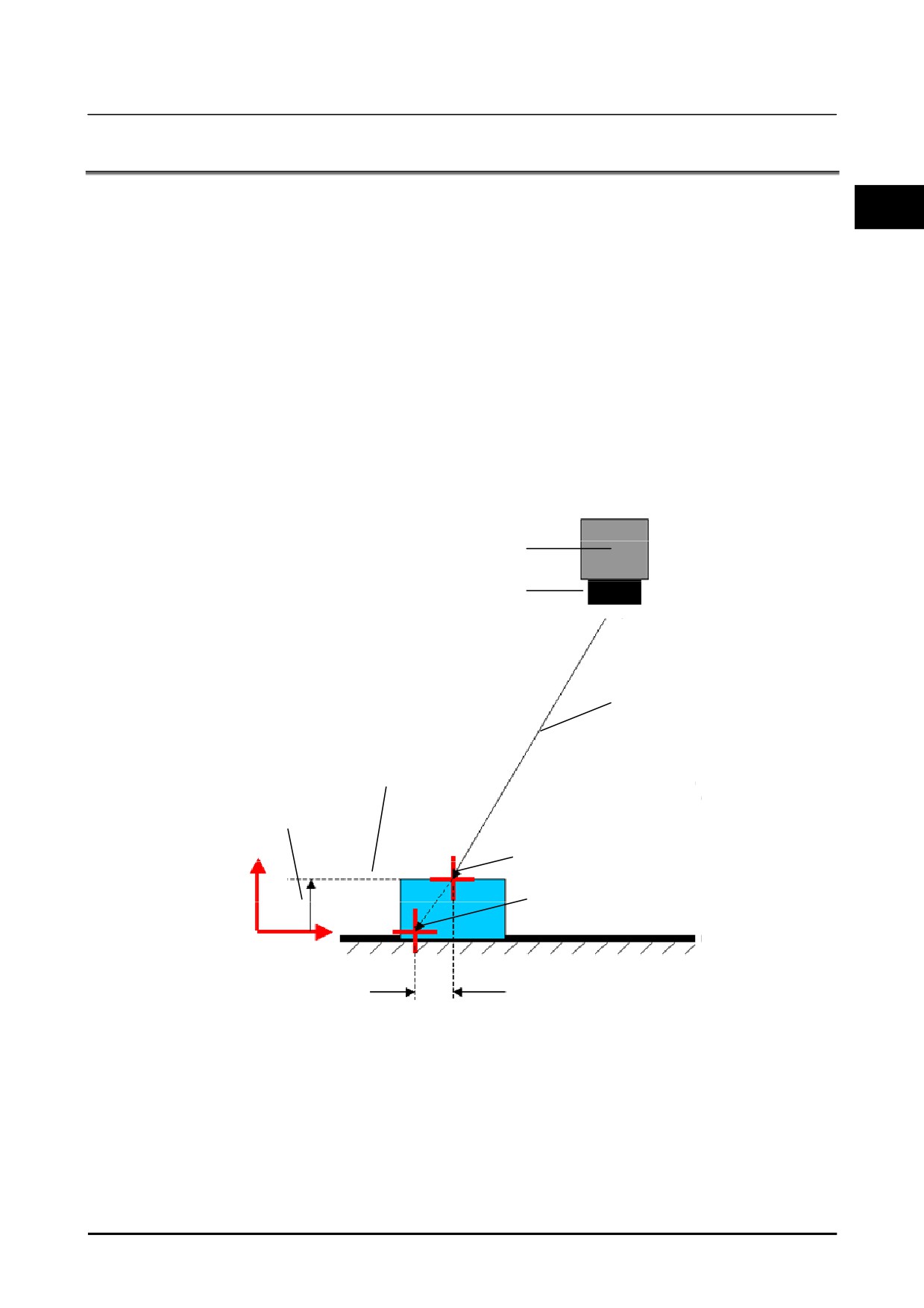
In the following figure, the two-dimensional camera detects a workpiece. In this case, the found position
2
of the workpiece will be in somewhere on the view line which connects from the workpiece to the
camera.
In order to determine the point on the view line, it is necessary to define the height of a workpiece (Part Z
Height) beforehand. In two-dimensional offset with iRVision, the height of the workpiece measurement
plane on the offset frame is used as the part z height. By setting up the part z height, the XY position of
the workpiece is correctly calculated. (“P1” in the following figure)
The part Z height is the important setting and which influences to the offset accuracy of the robot. So,
please set up the part Z height correctly. When the workpiece is in the center of field of view, the offset
error is too small, but when the workpiece moves to the edges of the field of view, the offset error
becomes large. In this case, it is possible that part Z height is not set properly. In the following figure,
when 0 mm is incorrectly set up in the part z height, the found position of the workpiece is calculated as it
is “P2”, and an offset error occurs in the XY direction.
Camera
Lens
View line
Workpiece measurement plane
Part Z Height
Z
Found position “P1”
Error position “P2”
XY
Offset frame
Detection error in the XY direction XY
Part Z Height
B-83914EN-2/01
13
2. ABOUT VISION SYSTEM
Introduction
2.7
MEMORY CARD PREPARATION
iRVision can save undetected images to a memory card or a USB memory inserted into the robot
controller. It is recommended that at the time of system start-up and integration, a memory card or a
USB memory be inserted to save undetected images to the memory card or a USB memory. By doing
so, the locator tool parameter can be adjusted using undetected images. Moreover, when the system is
reinstalled after being moved, for example, camera images before reinstallation, if saved, can be checked
against camera images after reinstallation to see if there is any major difference.
To enable vision log, check “Enable logging” on the iRVision configuration screen. For details, see
Section 1.7,”VISION CONFIG” in the iRVision operator's manual (Reference).
Note that even if "Log Failed Images" is set in the vision program, no un-detected images can be saved
when no memory card or no USB memory is inserted.
Moreover, if the log in a memory card or a USB memory increases, detection may take longer time. To
avoid this, it is recommended to export vision logs to a PC or other device periodically. For details, see
Section 3.2.5, ”VISION LOG” in the iRVision operator's manual (Reference).
When the free space of the memory device is less than the specified value (1 MB by default), old vision
logs are deleted to make enough free space for writing a new vision log. Even if the free space of the
memory card/USB memory is less than the specified value, files other than vision logs of the vision
system are not deleted. If there are no vision logs which can be deleted, the ‘CVIS-130 No free disk
space to log’ alarm is posted and the vision log will not be recorded.
CAUTION
1
As it takes a long time to delete the execution history, we recommend that you
regularly transfer the data for the execution history to your PC and ensure you
have sufficient free space in your memory card or USB memory. For details on
how to export the execution history to an external device or to delete it, refer to
Setup Edition Section 7.3, “VISION LOG MENU” in the R-30iB Plus Controller
iRVision OPERATOR’S MANUAL (Reference) B-83914EN.
2
On a memory card or USB memory, data other than execution history for
iRVision may be recorded. If the free space drops below the designated
capacity, the next time a vision Process is executed, history will be deleted until
the remaining capacity reaches the designated capacity. Depending on the
amount of data that is deleted, it may take a while to get into a state in which
execution of the next Vision Process can start. For example, saving a backup to
a memory card or USB memory corresponds to this case.
3
Do not insert a memory card in which execution history has been recorded using
another robot controller. If you carry out line execution or test execution of a
vision process with the memory card still inserted, the execution history that was
recorded using the original robot controller may be overwritten.
4
Format devices such as memory card or USB memory to FAT16.
5
If you record images, it may take time to execute detection. Basically, set things
up so that images will not be recorded after you have finished adjustment of the
vision system. For details, refer to Setup Edition Section 1.6, “EXECUTION
HISTORY” in the “R-30iB Plus CONTROLLER iRVision OPERATOR’S
MANUAL(Reference)B-83914EN ”.
A memory card or a USB memory, when inserted, can be used to back up all data in the robot controller.
If all data in the robot controller is backed up, the vision data can be backed up at the same time. Be
sure to back up all data in the robot controller upon completion of startup or integration.
14
B-83914EN-2/01
Introduction
2. ABOUT VISION SYSTEM
Moreover, use a memory card or a USB memory recommended by FANUC. If a memory card or a USB
memory other than those recommended is used, a normal operation is not guaranteed, and a bad influence
may occur on the controller.
2
2.8
CALIBRATION GRID
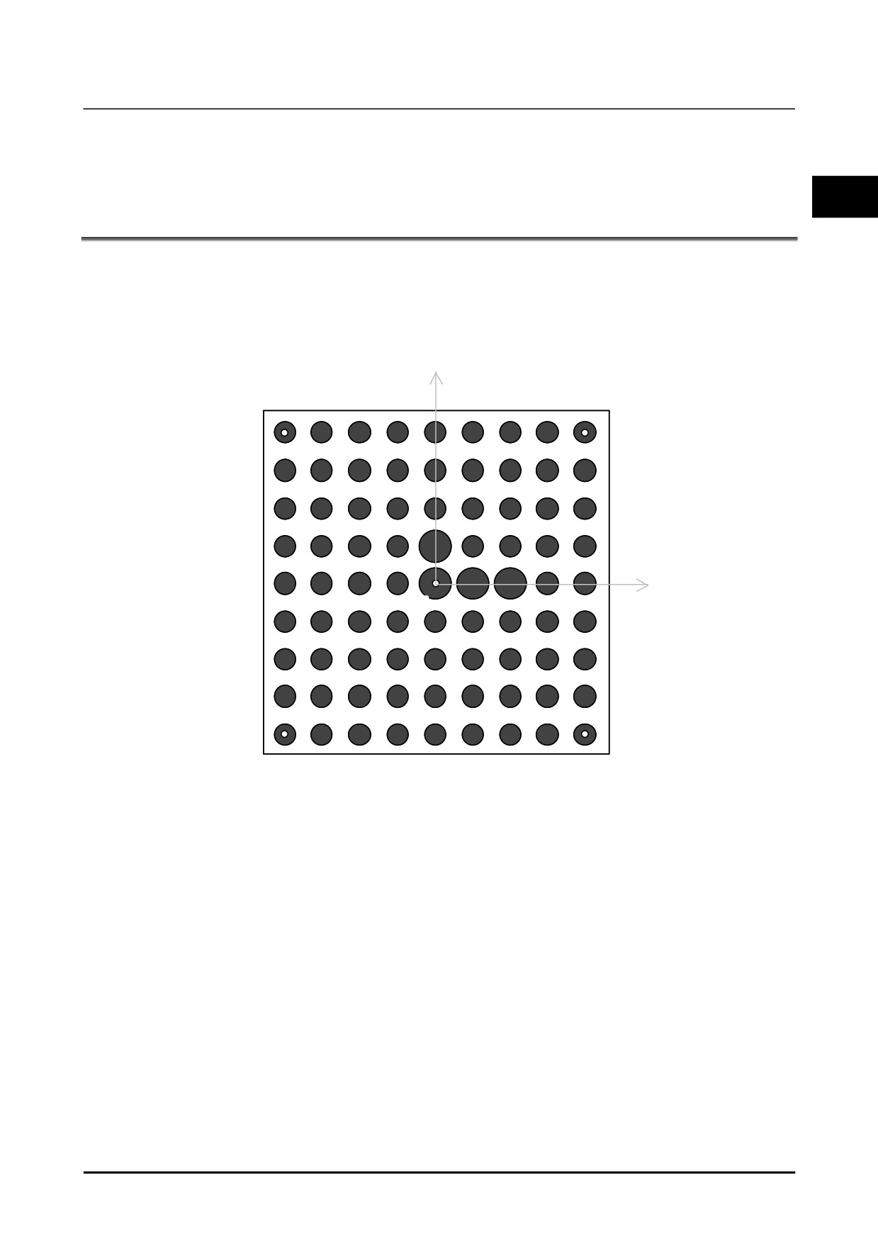
A calibration grid is a multi-purpose jig that is used for a variety of purposes, such as grid pattern
calibration and grid frame setting.
In iRVision, a calibration of a camera is performed using a calibration grid with a default pattern drawn.
When the camera snaps an image of the grid as shown below, iRVision automatically recognizes the
positional relationship of the calibration grid and the camera, lens distortion, the focal distance, etc.
Y
Origin
X
Example of a frame using a calibration grid
All the black dots of the calibration grid are arrayed in a square lattice. There are four large black dots
near the center that indicate the frame origin and direction as shown in the picture. The ratio of the
diameter of a large black dot to that of other black dots is approximately 10:6.
For the five grid points arranged in the center and at the four corners, there is a white dot with a diameter
of 1 mm placed at the center of the black dot. This white dot is used when setting the frame with
touch-up using the robot's TCP.
Depending on the application, a calibration grid can be used by fixing it to a table or attaching it to the
robot's gripper. In either case, it is necessary to set the arrangement position and direction (mounting
information) of the calibration grid when performing calibration for the camera.
To set up the information for mounting the calibration grid, attach a pointer tool to the robot's gripper and
set it up by physically performing touch-up
(calibration grid setting using touch-up), or set it up
automatically without any contact by using a camera and measuring a grid pattern (grid frame setting).
B-83914EN-2/01
15
3. FEATURES
Introduction
3 FEATURES
The following four application methods are explained below.
•
2D Single-view Vision Process
•
2D Multi-view Vision Process
•
Depalletizing Vision Process
•
3D Tri-View Vision Process
The 2D Single-view Vision Process and 2D Multi-view Vision Process can detect the parallel movement
of the workpiece, (X, Y) direction or the rotational movement (R) direction, and offset the robot position.
The Depalletizing Vision Process can detect not only the parallel movement (X, Y, R) but also the height
(Z) of the workpieces. The 3D Tri-View Vision Process can detect the (X, Y, Z, W, P, R) of the
workpiece.
This chapter explains the outlines of the above four applications, and Chapters 1 to 7 explain the setup
procedures in detail. The 2D Single-view Vision Process is the most standard vision application. The
setup procedure of the 2D Single-view Vision Process can apply to other vision application settings.
For details of each setting item, refer to the iRVision Operator’s Manual (Reference) B-83914EN.
3.1
OVERVIEW OF 2D SINGLE VIEW VISION PROCESS
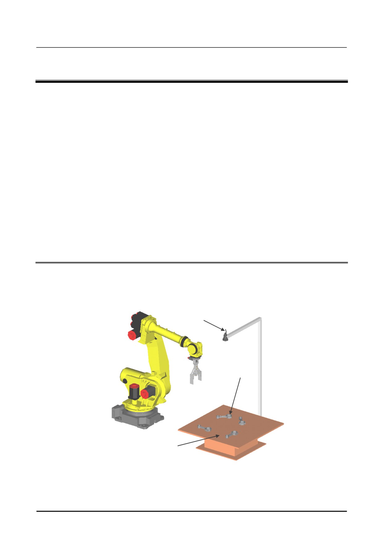
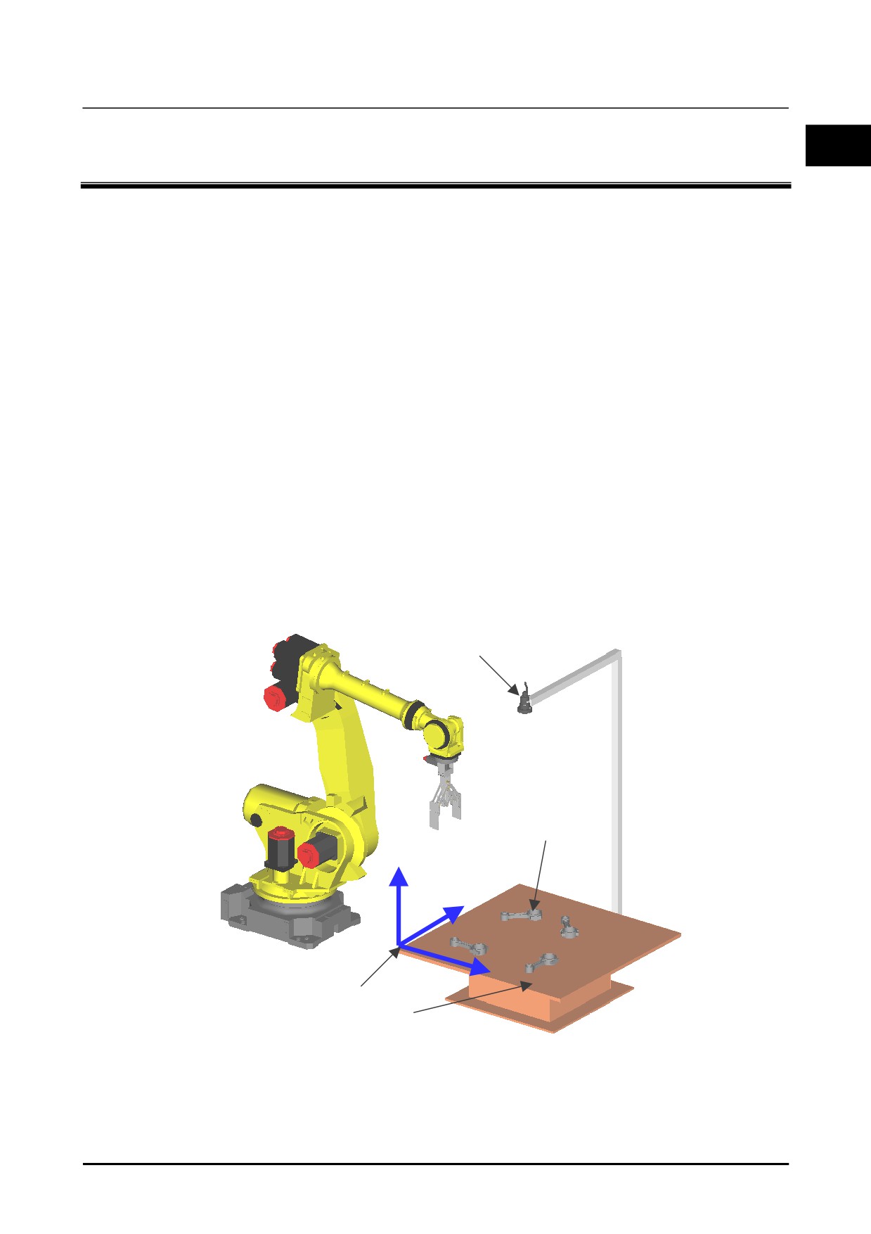
The 2D Single-view Vision Process can detect the workpiece on a plane with a camera and offset the
robot position depending on the parallel movement (X, Y) direction or the rotational movement (R)
direction of the workpiece. An example of the system layout is shown below. The robot detects the
workpiece on the table and picks up it.
Camera
Workpiece
Table
Example of layout for 2-D Single-View Vision Process
16
B-83914EN-2/01
Introduction
3. FEATURES
3.2
OVERVIEW OF 2D MULTI-VIEW VISION PROCESS
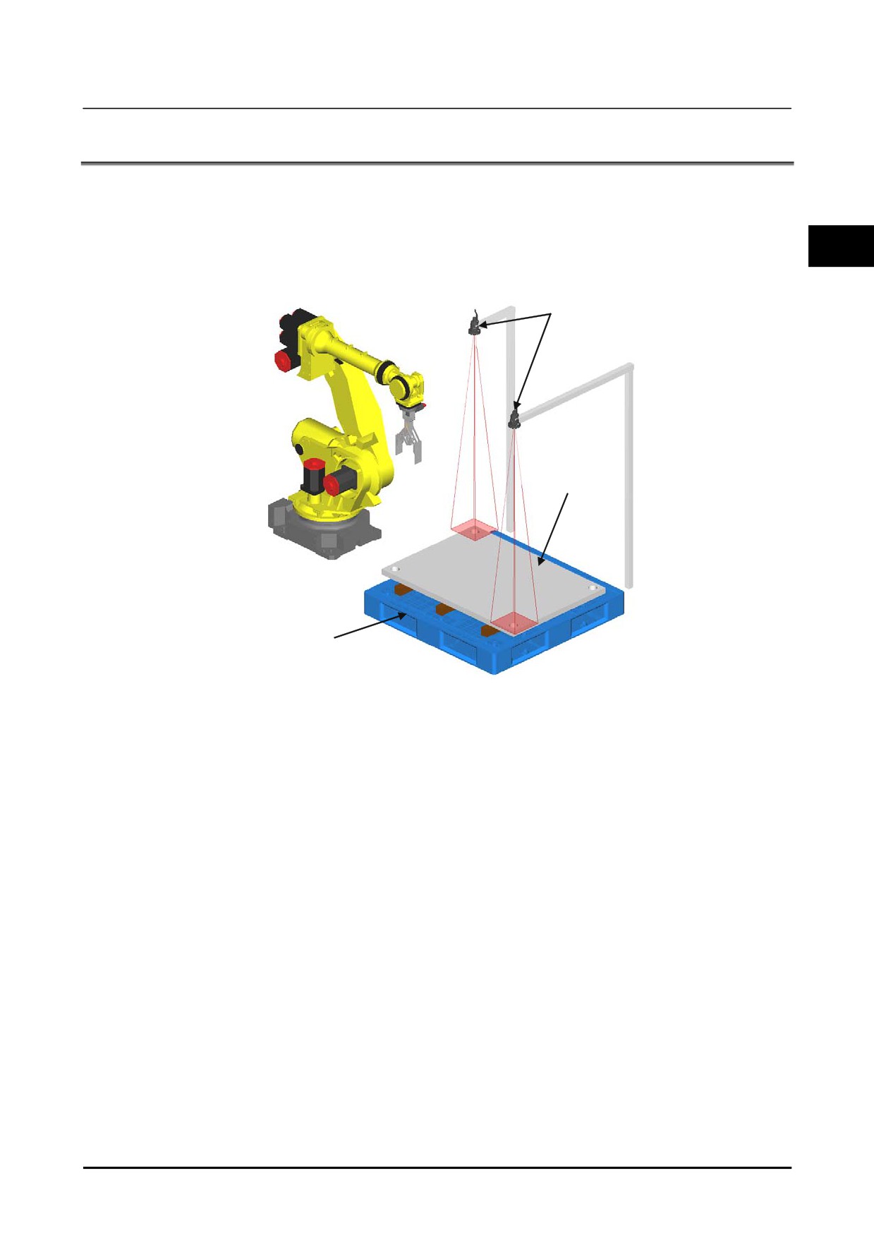
The 2D Multi-view Vision Process measures the multiple points of a workpiece and offset the robot
position in the two-dimensional. This function is used to measure multiple points of a large workpiece
that cannot be contained in the field of view of a single camera.
An example of the system layout is shown below. By using the two cameras, the robot detects the two
3
corners of the large workpiece and picks up the workpiece.
Camera
Workpiece
Pallet
Example of layout for 2-D Multi-View Vision Process
B-83914EN-2/01
17
3. FEATURES
Introduction
3.3
OVERVIEW OF DEPALLETIZING VISION PROCESS
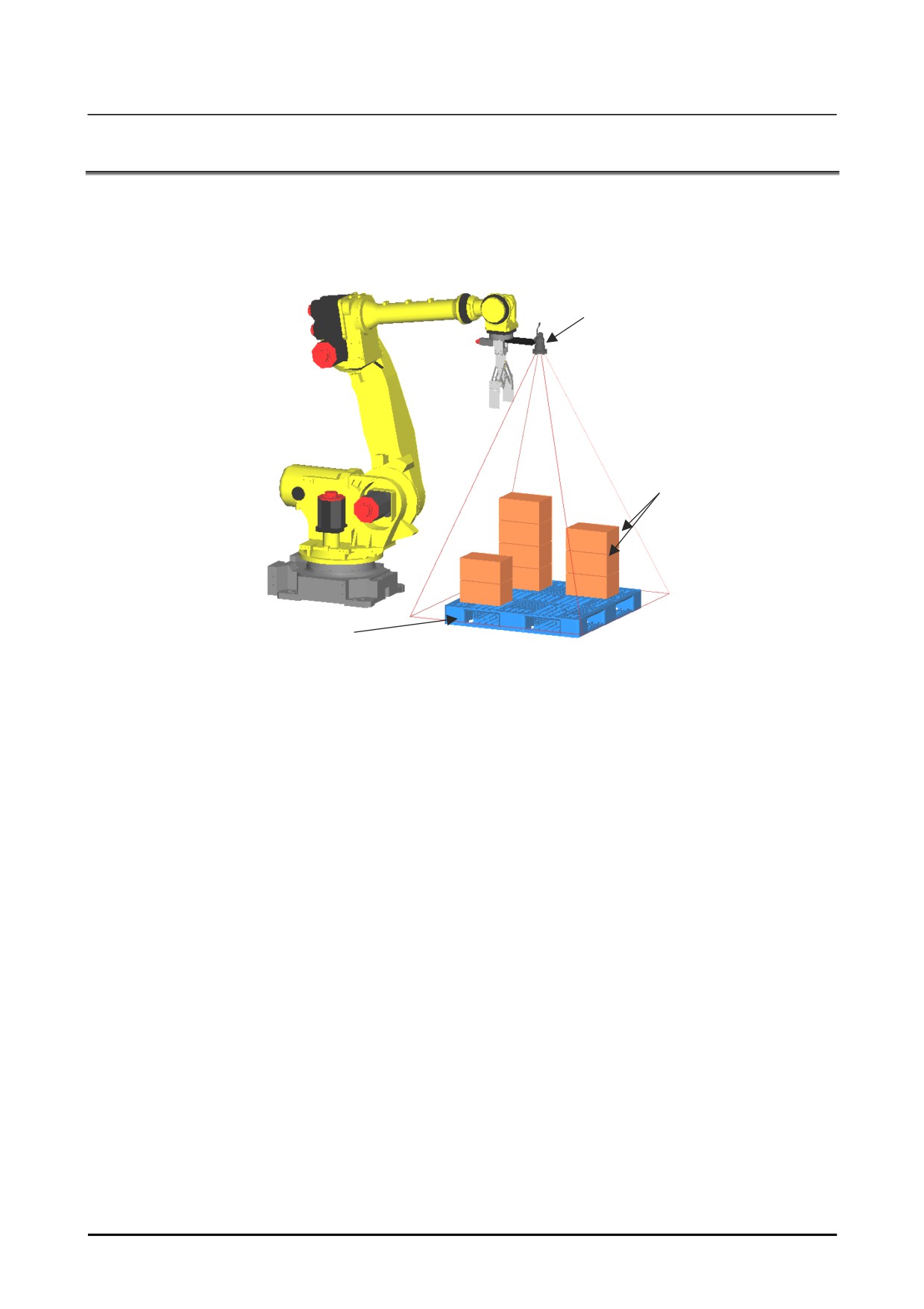
The Depalletizing Vision Process can measure not only the parallel movement of the workpiece but also
the vertical direction of the workpiece. This function can measure the height of the workpieces based on
the size of the workpiece in image. An example of the layout is shown below. The robot detects the
stacked workpieces on the pallet and picks up there in order from the highest workpiece.
Camera
Workpiece
Pallet
Example of layout for Depalletizing Vision Process
18
B-83914EN-2/01
Introduction
3. FEATURES
3.4
OVERVIEW OF 3D TRI-VIEW VISION PROCESS
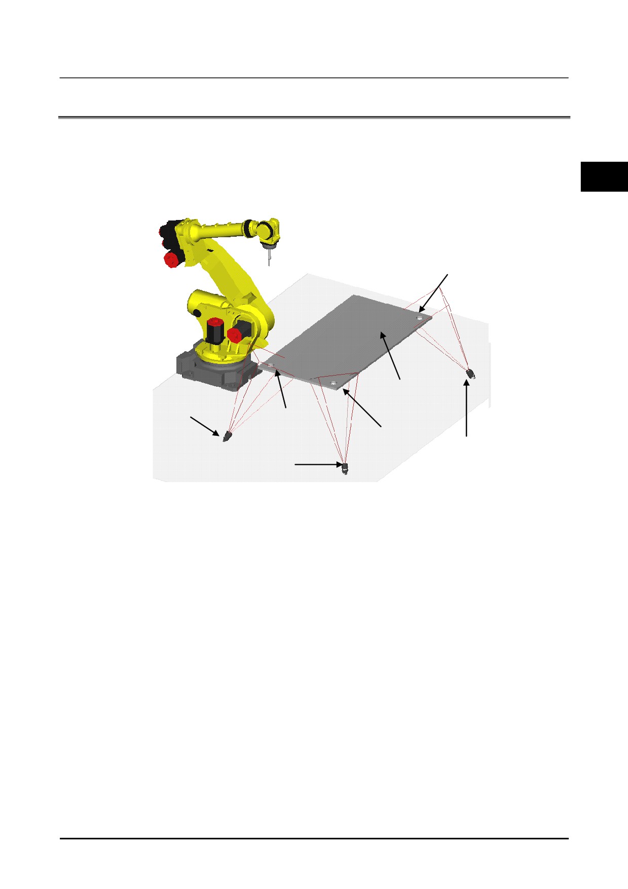
The 3D Tri-View Vision Process measures the three points of a large workpiece such as a car body, and
offsets the robot in the three-dimensional The offset applies to all of six degrees of freedom for parallel
displacement (X, Y, Z) and rotation (W, P, R) of the workpiece. An example of the layout is shown
below. The robot measures the three points of a large workpiece and offset the robot positions in the
3
three-dimensional.
Target3
Workpiece
Camera1
Target1
Target2
Camera3
Camera2
Example of layout for 3-D Tri-View Vision Process
B-83914EN-2/01
19
Setup
1. 2D SINGLE VIEW VISION PROCESS
1
1
2D SINGLE VIEW VISION PROCESS
The 2D Single-view Vision Process can detect the workpiece on a plane with a camera and offset the
robot position depending on the parallel movement (X, Y) direction or the rotational movement (R)
direction of the workpiece. The 2D Single-view Vision Process can be used in the following four
configurations:
• Fixed frame offset with a fixed camera
• Fixed frame offset with a robot-mounted camera
• Tool offset with a fixed camera
• Tool offset with a robot-mounted camera
This chapter describes the setup procedure for a 2D Single-view Vision Process by using the following
three application examples:
‘Fixed frame offset with a fixed camera’,
‘Fixed frame offset with a
robot-mounted camera’ and ‘Tool offset with a fixed camera’.
In the configuration of ‘Tool offset with a robot-mounted camera’, a robot A holds the camera and robot
B holds the workpiece, and the robot A measures the grip error of the workpiece. The current position
of each robot is needed, so the inter-robot communication function should be set to communicate between
each robot. If a robot A is held a camera but it used as a fixed camera, the setup procedures is same as
‘Tool offset with a fixed camera’.
Fixed frame offset with a fixed camera
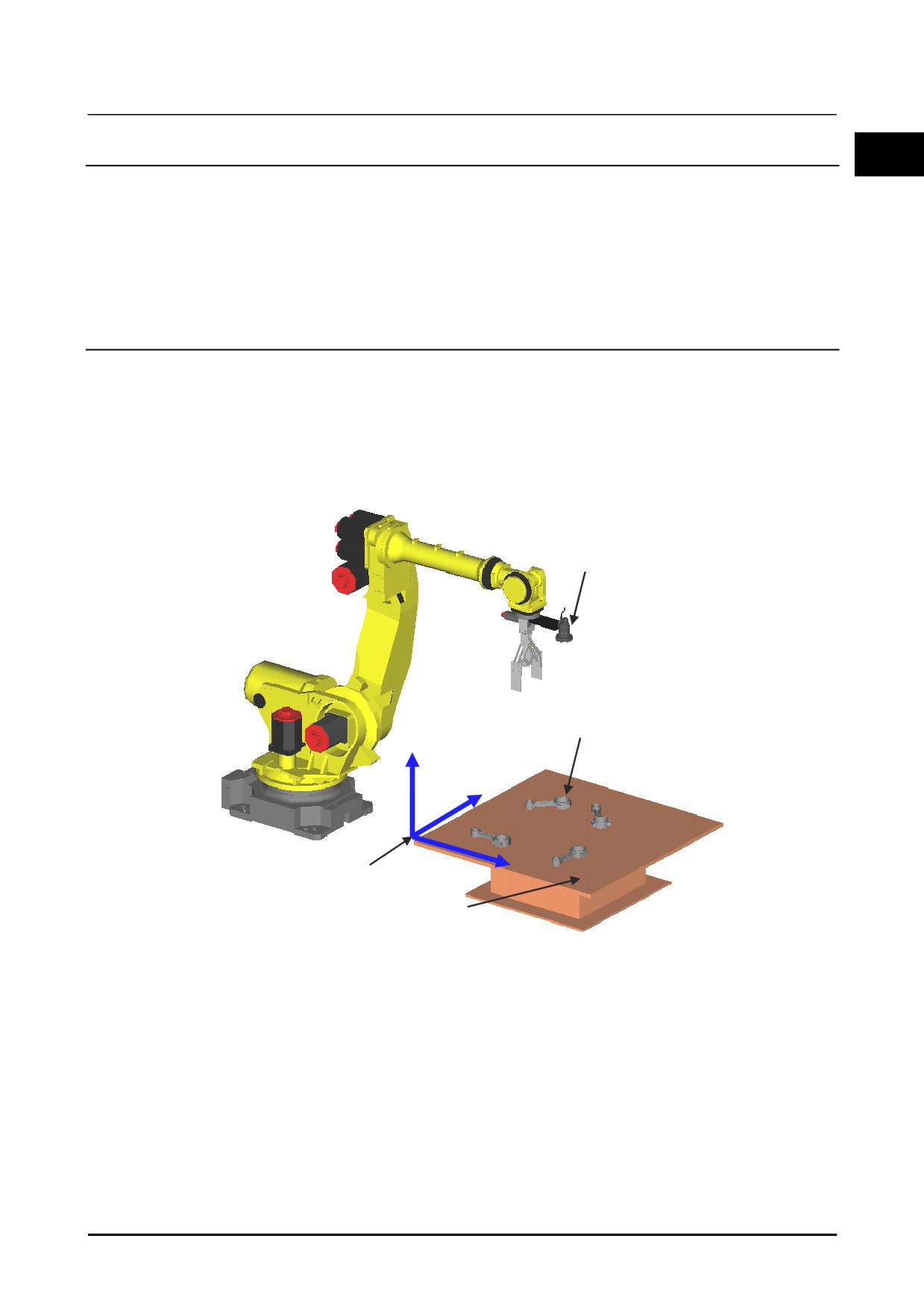
An example of a layout for a ‘fixed frame offset with a fixed camera’ is shown below.
Camera
Workpiece
Z
Y
X
Offset frame
Table
Example of a layout for a fixed frame offset with a fixed camera
B-83914EN-2/01
23
1. 2D SINGLE VIEW VISION PROCESS
Setup
Fixed frame offset with a robot-mounted camera
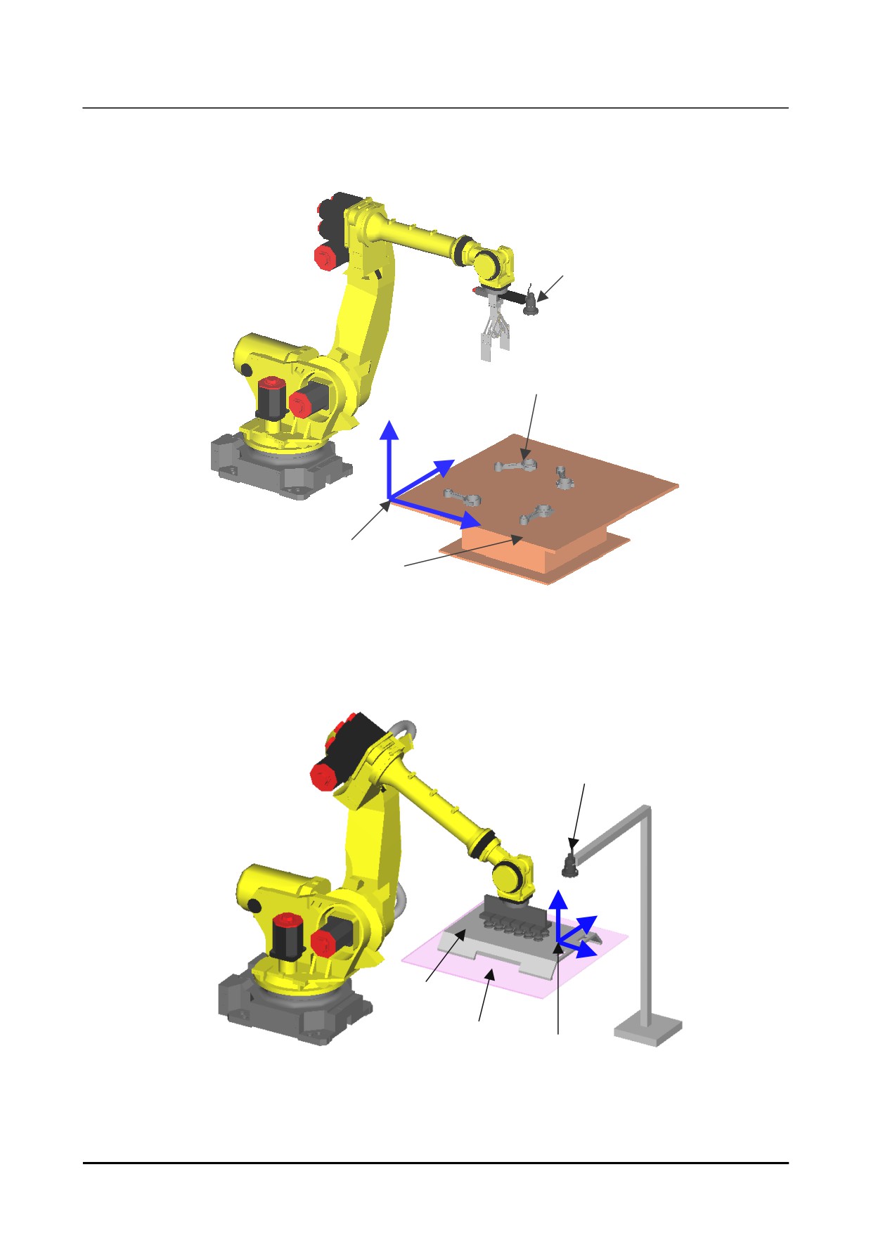
An example of a layout for a ‘fixed frame offset with a robot-mounted camera’ is shown below.
Camera
Workpiece
Z
Y
X
Offset frame
Table
Example of a layout for a fixed frame offset with a robot-mounted camera
Tool offset with a fixed camera
An example of a layout for a ‘tool offset with a fixed camera’ is shown below.
Camera
Z
Y
X
Workpiece
Workpiece deviation plane
Offset frame
Example of a layout for a tool offset with a fixed camera
24
B-83914EN-2/01
Setup
1. 2D SINGLE VIEW VISION PROCESS
1.1
FEATURES AND NOTES
1
Features
•
2D single-view vision process is the most standard application of a 2-D view vision process.
•
It supports the fixed frame offset and the tool offset.
•
Both a fixed camera and a robot-mounted camera can be used.
•
When a robot-mounted camera is used, even if when the robot moves the camera in the X and Y
directions on the offset frame, the position of a workpiece can be measured. This is because,
iRVision calculates the positions of the workpiece based on the current position of the robot.
Notes
• The offset is applied to the XY and R directions. Therefore, each measurement plane should be
parallel to the XY plane of the offset frame and should not be tilted.
• Ideally, the optical axis of the camera should be vertical to the XY plane of the offset frame. When
the position of the camera is tilted against the measurement points of the workpiece, the shape of the
workpiece in the image may change depending on the location of the workpiece, so the detection
may become difficult.
1.2
SETUP FOR FIXED FRAME OFFSET WITH FIXED
CAMERA
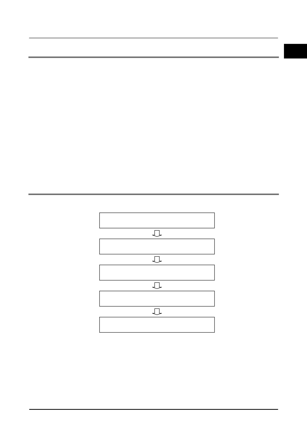
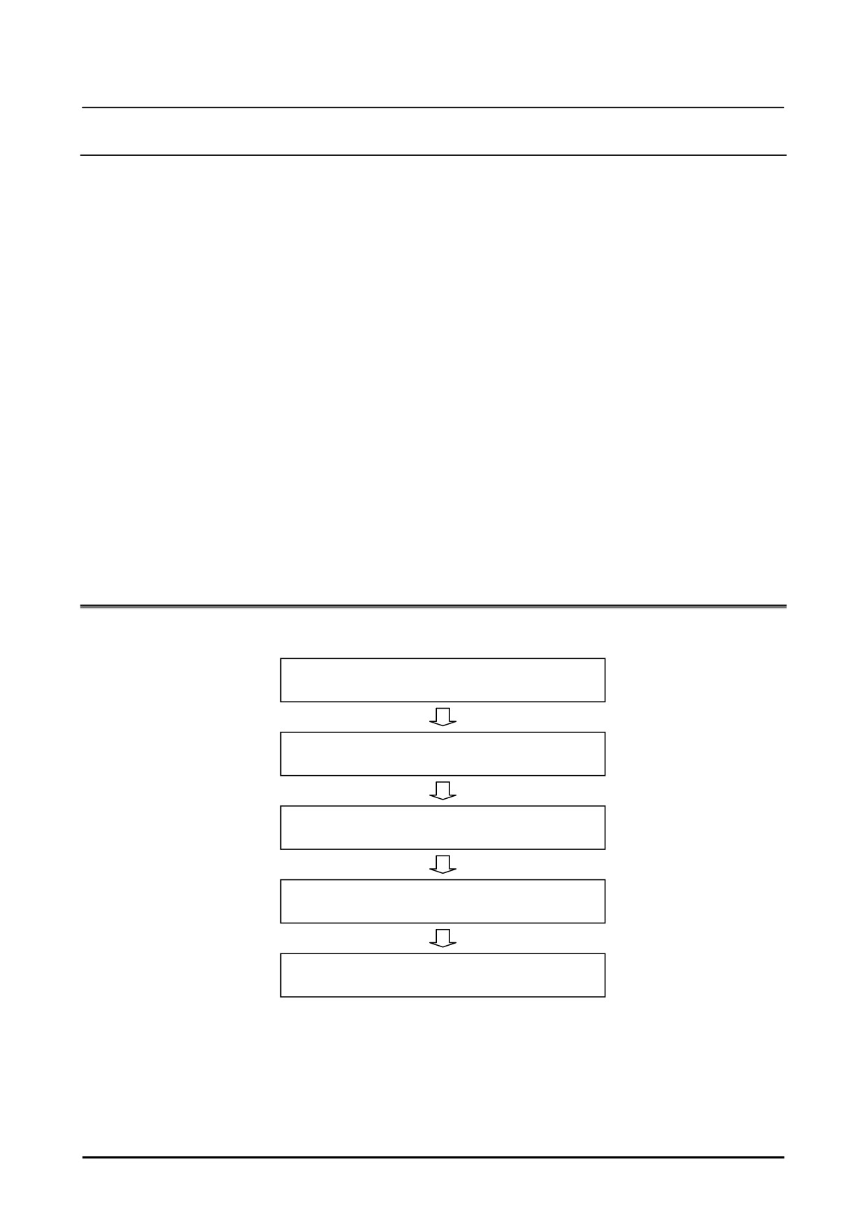
The setup procedures for the fixed frame offset with the fixed camera is shown below:
1.
Camera Data Creation and Teaching
2.
Offset frame setting
3.
Vision process creation and teaching
4.
Robot program creation and teaching
5.
Robot compensation operation check
When create the vision system newly, perform all of the above procedures. When the position of the
installed camera is changed or the cameras are exchanged, redo the camera calibration in ‘1 Camera Data
Creation and Teaching’. When you need to add a new kind of workpiece, if a camera calibration has
been already done, the re-calibration of the camera is not needed. Perform ‘3 Vision process creation
and teaching’ and ‘4 Robot program creation and teaching’.
B-83914EN-2/01
25
1. 2D SINGLE VIEW VISION PROCESS
Setup
1.2.1
Camera Data Creation and Teaching
Create a camera data and perform basic settings and calibration of the camera.
The Grid Pattern Calibration and the Robot-generated Grid Calibration can be used to calibrate a fixed
camera.
• For details of the grid pattern calibration, refer to Know-how Edition Section 2.1, "GRID PATTERN
CALIBRATION WITH A FIXED CAMERA".
• For details of robot-generated grid calibration, refer to Know-how Edition Section
2.3,
"ROBOT-GENERATED GRID CALIBRATION".
1.2.2
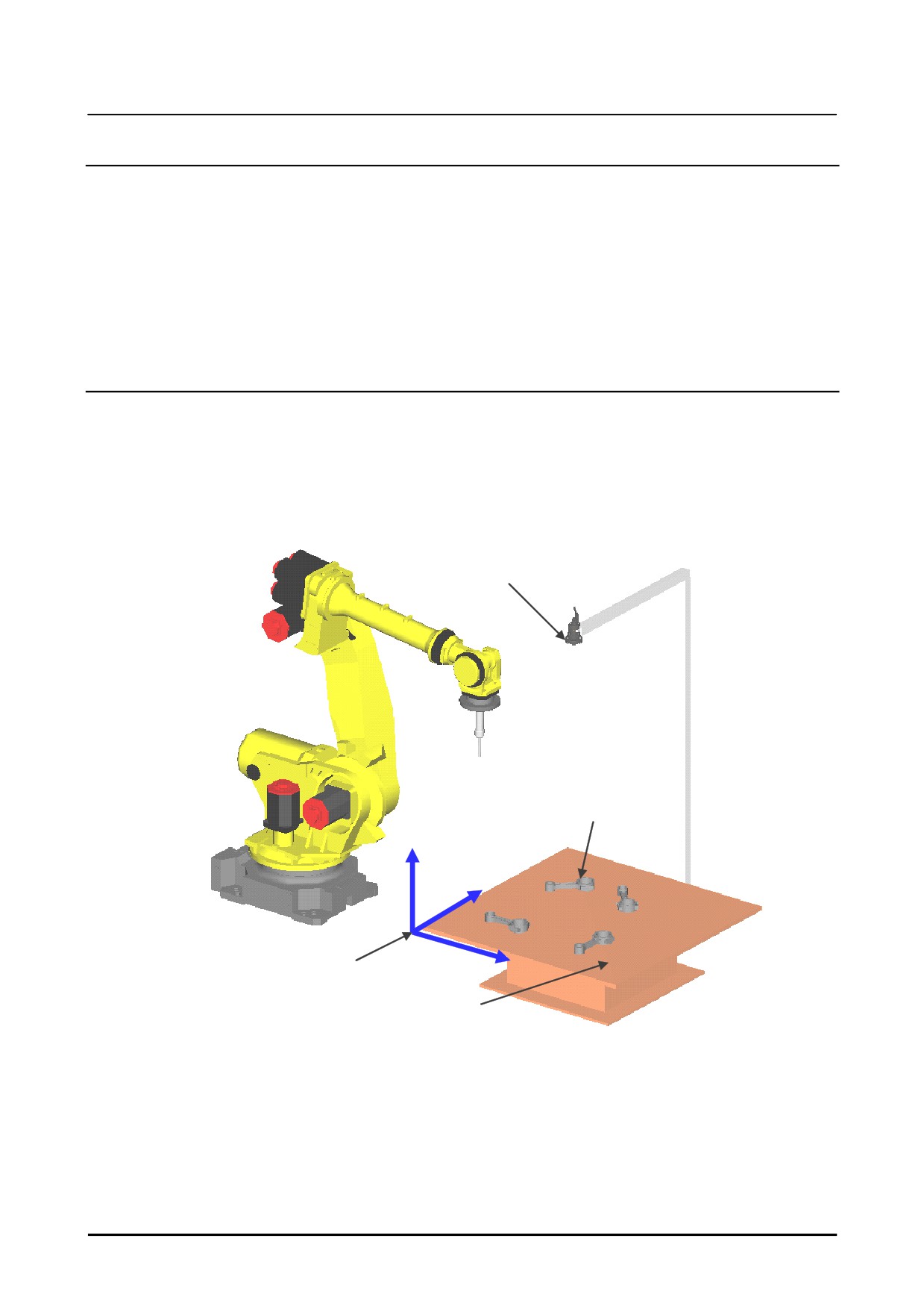
Offset Frame Setting
The offset frame is used for the calculation of the offset data in the 2D Single-view Vision Process. The
position of a found workpiece is outputted as the position on the offset frame. In the fixed frame offset,
the offset frame is set as a user frame.
Set an offset frame so that the XY plane of the offset frame is parallel with the table plane where the
workpiece is placed. When the offset frame is not parallel with the plane where the workpiece is placed,
the accuracy of offset may become low.
Camera
Workpiece
Z
Y
X
Offset Frame
Table
Offset Frame setting
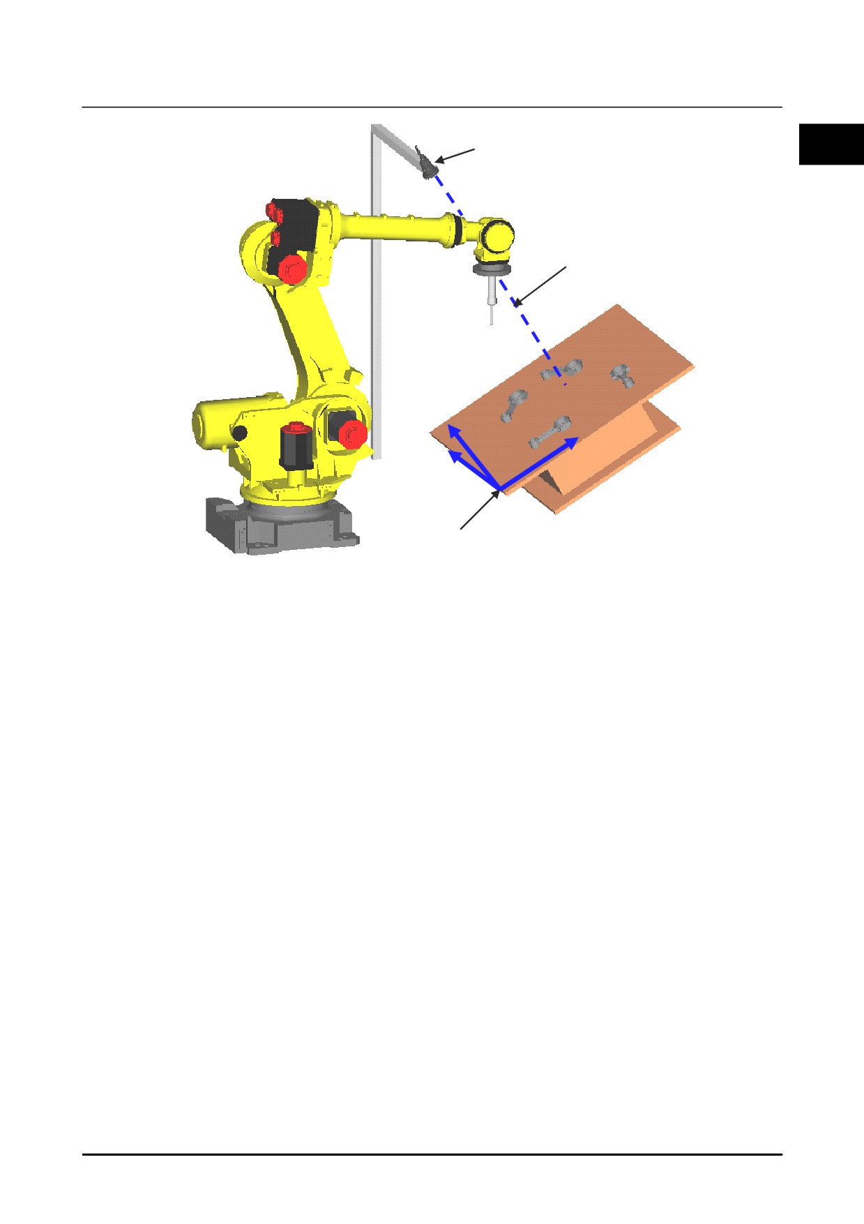
In the following figure, the plane where the workpiece are placed is tilt against the robot’s world frame.
Set the offset frame so that the plane where the workpiece are placed is parallel with the XY plane of the
offset frame.
26
B-83914EN-2/01
Setup
1. 2D SINGLE VIEW VISION PROCESS
Camera
1
Optical axis of a camera
Z
X
Y
Offset Frame
Offset Frame setting (When an inclined work table is installed)
‘Touch-up with the pointer tool’ and ‘Automatic Grid Frame Setting Function’ can be used to set the
offset frame.
Touch-up
When set the user frame by touch-up method, a pointer tool with TCP is needed. In general, attach the
pointer tool to the robot hand and set the TCP accurately at the tip of the pointer tool. If the accuracy of
TCP setting is low, the accuracy of the offset is also degraded. Set a TCP in an arbitrary tool frame.
When you reuse the pointer tool later, install the pointer tool in where the same location as when the TCP
setting had performed. If the reproducibility of pointer installation is not assured, a TCP setting needs
again. For details, refer to Know-how Edition Subsection 1.1.1, "User Frame Setting".
Grid Frame Setting Function
The Grid Frame Setting Function sets the user frame on the calibration grid frame by using a camera.
Install a calibration grid so that the XY plane of the calibration grid is parallel with the plane where the
workpiece is placed, and perform the Grid Frame Setting Function. For details, refer to Know-how
Edition Section
1.2, "FRAME SETTING WITH THE GRID FRAME SETTING FUNCTION".
When a fixed camera is used, prepare another temporary camera to perform the Grid Frame Setting
Function. The Grid Frame Setting Function can be only used with the 6-axis robot. This function
cannot be used with the 4-axis robot and the 5-axis robot. When the 4-axis robot or the 5-axis robot is
used, use the touch-up method.
B-83914EN-2/01
27
1. 2D SINGLE VIEW VISION PROCESS
Setup
1.2.3
Vision Process Creation and Teaching
Create a vision process and teach it. In addition, teach the locator tools and set the reference position.
1.2.3.1 Vision process creation
1
Create a vision process for [2-D Single-View Vision Process].
For details of the vision process creation, refer to Setup Edition Subsection 1.3.1.1, "Create" in the
"R-30iB Plus Controller iRVision Operator's MANUAL(Reference) B-83914EN".
2
On the vision data list screen, when a created vision process is selected and clicked [Edit], the vision
data edit screen will appear.
3
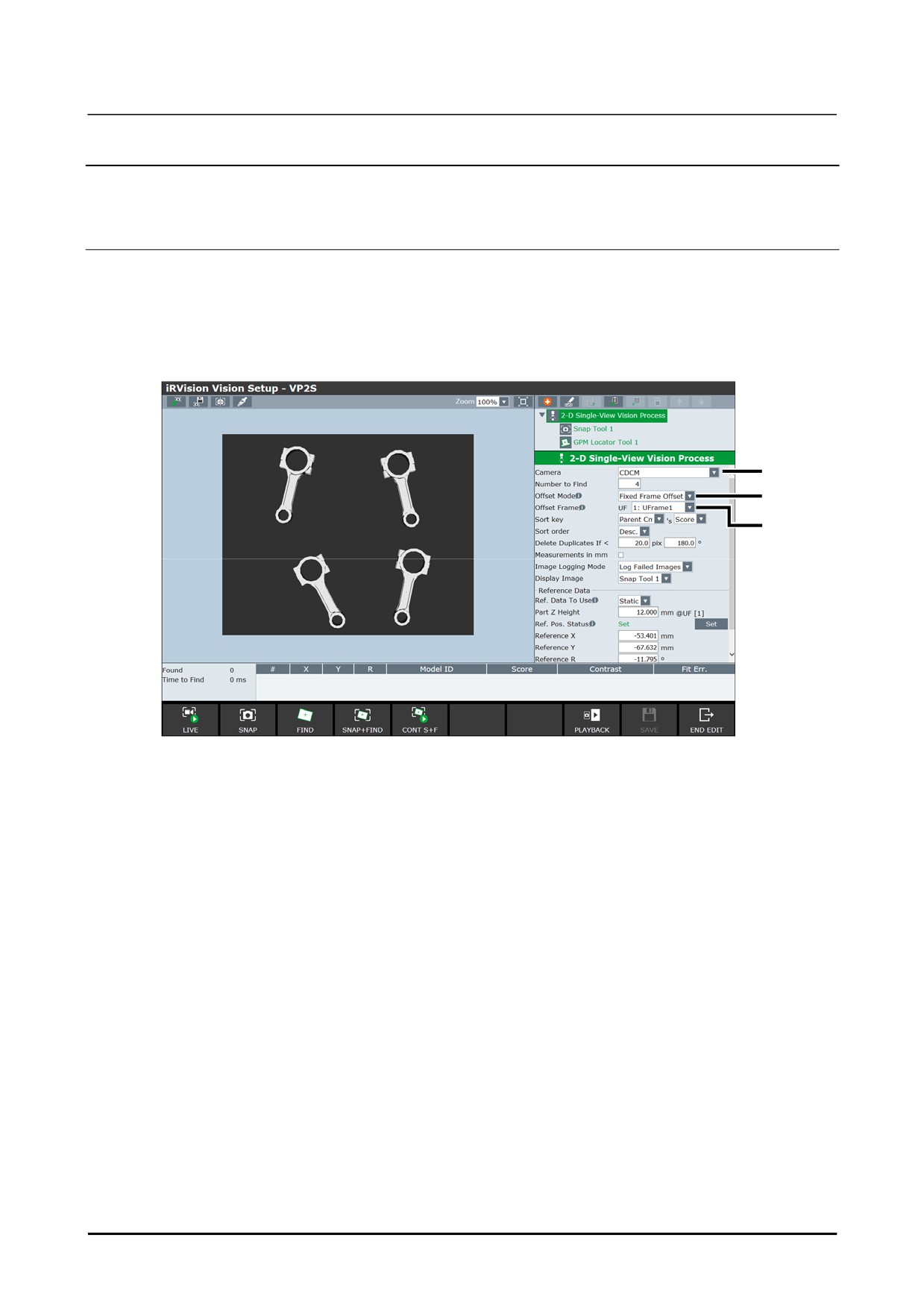
4
5
3
From the [Camera] drop-down box, select the camera data to be used.
Select the camera data specified in Setup Edition Subsection 1.2.1, "Camera Data Creation and
Teaching".
4
From the [Offset Mode] drop-down box, select [Fixed Frame Offset].
5
From the [Offset Frame] drop-down box, select the user frame to set.
Select the frame number specified in Setup Edition Subsection 1.2.2, "Offset Frame Setting".
28
B-83914EN-2/01
Setup
1. 2D SINGLE VIEW VISION PROCESS
1.2.3.2 Command tool teaching
1
1
Place a workpiece in the field of view of the camera.
2
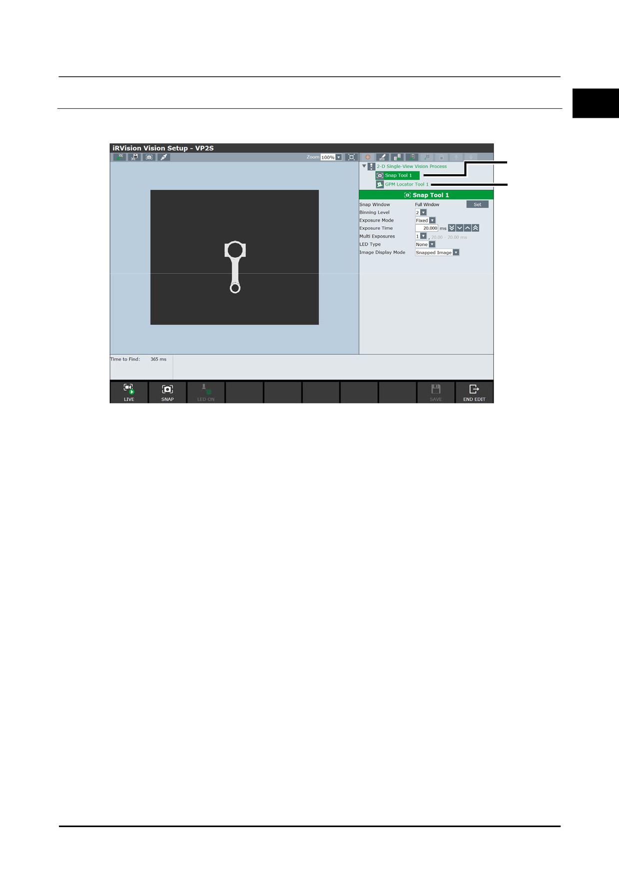
3
2
Set up the snap tool.
The snap tool is a tool that snaps images that are used to teach and find models. Set the snap
conditions such as the snap window and the exposure time. For details, refer to Setup Edition
Section
4.1, "SNAP TOOL" in the "R-30iB Plus CONTROLLER iRVision OPERATOR’S
MANUAL (Reference) B-83914EN".
3
Select a locator tool from the tree view and teach the model to use for detection.
By default, the GPM Locator Tool is set as the locator tool. For details of the GPM Locator Tool
and other command tools, refer to Setup Edition Section 4, "COMMAND TOOLS" in "R-30iB Plus
CONTROLLER iRVision OPERATOR’S MANUAL (Reference) B-83914EN".
B-83914EN-2/01
29
1. 2D SINGLE VIEW VISION PROCESS
Setup
1.2.3.3 Reference position setting
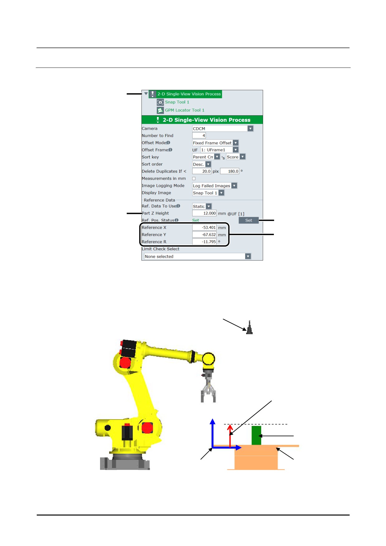
1
Select [2-D Single-View Vision Process] from the tree view.
1
2
4
5
2
In the text box for [Part Z Height], enter the height of the detected part of the workpiece.
When the XY plane of the offset frame is apart from the detected part of the workpiece, enter the
distance.
Enter an appropriate value as shown in the figure below.
Camera
Part Z Height
Z
Workpiece
X
Table
Offset Frame
Offset Frame and Part Z Height
30
B-83914EN-2/01
Setup
1. 2D SINGLE VIEW VISION PROCESS
3
Click [SNAP] and snap the image, and click [FIND] to detect the workpiece.
1
CAUTION
Do not move the workpiece until the reference position setting is complete.
4
Click the [Set] button for [Ref. Pos. Status]
5 Check that [Ref. Pos. Status] has become [Set] and make sure that there are values for [Reference X],
[Reference Y] and [Reference R].
The values are the origin of the workpiece on the offset frame.
6
Click [SAVE] and click [END EDIT].
7 Move the robot to the position where work to the workpiece (e.g. gripping it).
For an example, refer to the sample program in Setup Edition Subsection 1.2.4, "Robot Program
Creation and Teaching". P[2] in line 11 is the position to work to the workpiece. Record the
current robot position to P[2], and the reference position teaching is complete.
1.2.4
Robot Program Creation and Teaching
The sample program is shown below. A vision process "A" is used. Add the
"VOFFSET, VR"
instruction to the movement statement.
1:
UFRAME_NUM=1 ;
2:
UTOOL_NUM=1 ;
3:
R[1:Notfound]=0
;
4:L P[1] 2000mm/sec FINE
;
5:
;
6:
VISION RUN_FIND 'A'
;
7:
VISION GET_OFFSET 'A' VR[1] JMP LBL[100] ;
8:
;
9:
!Handling ;
10:L P[2] 2000mm/sec CNT100 VOFFSET,VR[1] Tool_Offset,PR[1]
;
11:L P[2] 500mm/sec FINE VOFFSET,VR[1]
;
12: CALL HAND_CLOSE
;
13:L P[2] 2000mm/sec CNT100 VOFFSET,VR[1] Tool_Offset,PR[3]
;
14:
!Handling ;
15:
JMP_LBL[900] ;
16:
;
17: LBL[100] ;
18: R[1:Notfound]=1
;
19:
;
20: LBL[900] ;
Execute the vision program "A" on line 6. Obtain the offset data on line 7. Move the robot to the
approach position above the workpiece on line 10. Move the robot to the grasp position on line 11.
Move the robot to escape position after grasping the workpiece on line 13.
B-83914EN-2/01
31
1. 2D SINGLE VIEW VISION PROCESS
Setup
1.2.5
Robot Compensation Operation Check
Check that a placed workpiece on the table can be detected and handled accuracy.
• Place the workpiece on the reference position, find it and check the handling accuracy. If the
accuracy of the offset is low, set the reference position again.
• Move the workpiece without rotation, find it and check the handling accuracy. If the accuracy of
the offset is good on the reference position but it lows on the edge of the field of view, it is possible
that
[Part Z Height] is not set properly. Check the
[Part Z Height], refer to Setup Edition
Subsection 1.2.3.3, "Reference position setting".
• Rotate the workpiece, find it and check the handling accuracy. If the accuracy of the offset is good
on the non-rotated workpiece but it lows on rotated workpiece, it is possible that the offset frame or
the calibration grid frame is not set properly. When set the frames using the touch-up method with
a pointer tool, check the TCP setting is precise. Moreover, check the offset frame and calibration
grid frame are set precisely. If there is necessary, retry the camera calibration. If it is difficult to
retry the camera calibration, the "ADJ_OFS" may improve the situation without the re-set up the
offset frame and the calibration grid location. ADJ_OFS is included in VISION SUPPORT
TOOLS. Refer to Setup Edition Subsection
8.1.6, "ADJ_OFS" in the "R-30iB Plus
CONTROLLER iRVision OPERATOR’S MANUAL (Reference) B-83914EN" for details.
• Start with lower override of the robot to check that the logic of the program is correct. Next,
increase the override to check that the robot can operate continuously.
1.3
SETUP FOR FIXED FRAME OFFSET WITH ROBOT
MOUNTED CAMERA
The setup procedures for the fixed frame offset with the robot mounted camera is shown below:
1.
Camera Data Creation and Teaching
2.
Offset frame setting
3.
Vision process creation and teaching
4.
Robot program creation and teaching
5.
Robot compensation operation check
When create the vision system newly, perform all of the above procedures. When the position of the
camera on the robot mechanical interface (the robot face plane) is changed or the cameras are exchanged,
redo the camera calibration in ‘1 Camera Data Creation and Teaching’. When you need to add a new
kind of workpiece, if a camera calibration has been already done, the re-calibration of the camera is not
needed. Perform ‘3 Vision process creation and teaching’ and ‘4 Robot program creation and teaching’.
32
B-83914EN-2/01
Setup
1. 2D SINGLE VIEW VISION PROCESS
1.3.1
Camera Data Creation and Teaching
1
Create a camera data and perform basic settings and calibration for the camera.
When a robot-mounted camera is used, perform the ‘Grid Pattern Calibration’. When a robot-mounted
camera is used, the ‘Robot-Generated Grid Calibration’ cannot be used. For details of the grid frame
calibration, refer to Know how Edition Section 2.2, "GRID PATTERN CALIBRATION WITH A
ROBOT-MOUNTED CAMERA".
1.3.2
Offset Frame Setting
The offset frame is used for the calculation of the offset data in the 2D Single-view Vision Process. The
position of a found workpiece is outputted as the position on the offset frame. In the fixed frame offset,
the offset frame is set as a user frame.
Set an offset frame so that the XY plane of the offset frame is parallel with the table plane where the
workpiece is placed. When the offset frame is not parallel with the plane where the workpiece is placed,
the accuracy of offset may become low.
Robot-mounted camera
Workpiece
Z
Y
X
Offset Frame
Table
Offset Frame setting
There are two methods to teach the offset frame, one is touch-up with the pointer tool, and another is the
Automatic Grid Frame Setting Function.
Touch-up
When set the user frame by touch-up method, a pointer tool with TCP is needed. In general, attach the
pointer tool to the robot hand and set the TCP accurately at the tip of the pointer tool. If the accuracy of
TCP setting is low, the accuracy of the offset is also degraded. Set a TCP in an arbitrary tool frame.
When you reuse the pointer tool later, install the pointer tool in where the same location as when the TCP
setting had performed. If the reproducibility of pointer installation is not assured, a TCP setting needs
again. For details, refer to Know-how Edition Subsection 1.1.1, "User Frame Setting".
B-83914EN-2/01
33
1. 2D SINGLE VIEW VISION PROCESS
Setup
Grid Frame Setting Function
The Grid Frame Setting Function sets the user frame on the calibration grid frame by using a camera.
Install a calibration grid so that the XY plane of the calibration grid is parallel with the plane where the
workpiece is placed, and perform the Grid Frame Setting Function. For details, refer to Know-how
Edition Section 1.2, "FRAME SETTING WITH THE GRID FRAME SETTING FUNCTION". When a
robot-mounted camera is used, the camera can be used for the Grid Frame Setting Function. When there
is not sufficient space to perform the Grid Frame Setting Function with the camera, prepare another
temporary robot-mounted camera and perform the Grid Frame Setting Function. The Grid Frame
Setting Function can be only used with the 6-axis robot. This function cannot be used with the 4-axis
robot and the 5-axis robot. When the 4-axis robot or the 5-axis robot is used, use the touch-up method.
1.3.3
Vision Process Creation and Teaching
Create a vision process and teach it. In addition, teach the locator tools and set the reference position.
1.3.3.1 Vision process creation
1
Create a vision process for [2-D Single-View Vision Process].
For details of the vision process creation, refer to Setup Edition Subsection 1.3.1.1, "Create" in the
"R-30iB Plus CONTROLLER iRVision OPERATOR’S MANUAL (Reference) B-83914EN".
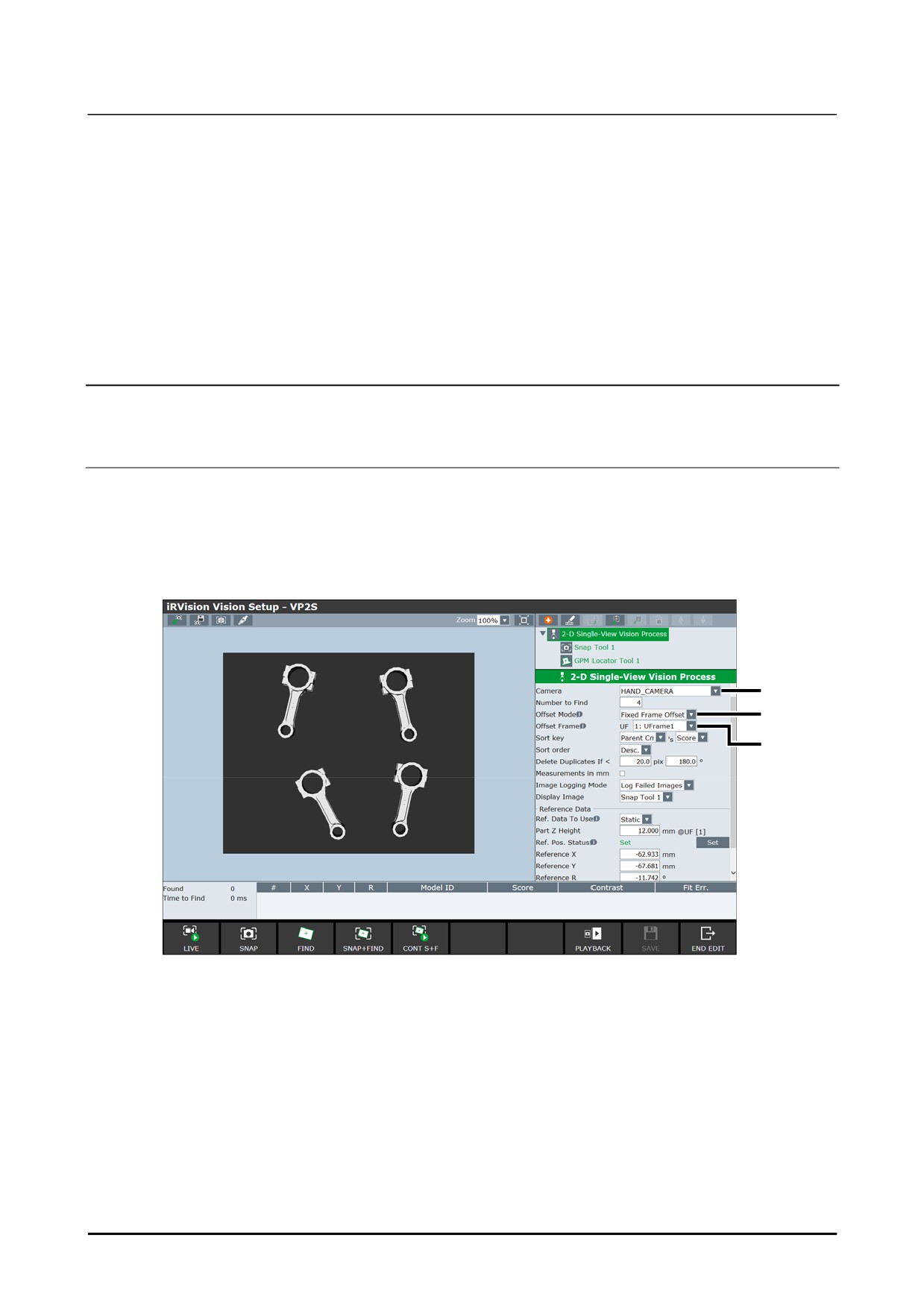
2
On the vision data list screen, when the created vision process is selected and clicked [Edit], the
vision data edit screen will appear.
3
4
5
3
From the [Camera] drop-down box, select the camera data to be used.
Select the camera data specified in Setup Edition Subsection 1.3.1, "Camera Data Creation and
Teaching".
4
From the [Offset Mode] drop-down box, select [Fixed Frame Offset].
5
From the [Offset Frame] drop-down box, select the user frame to set.
Select the frame number specified in Setup Edition Subsection 1.3.2, "Offset Frame Setting".
34
B-83914EN-2/01
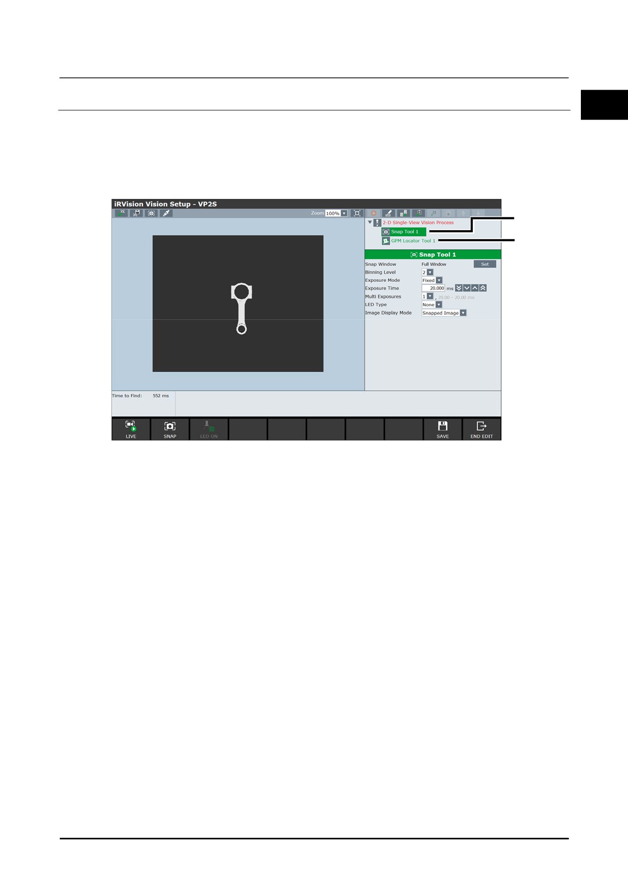
Setup
1. 2D SINGLE VIEW VISION PROCESS
1.3.3.2 Command tool teaching
1
1
Place a workpiece in the field of view of the camera.
2
Move the robot to the measurement position where the workpiece can be snapped.
Record this robot position as the first measurement position. Refer to the sample program in Setup
Edition Subsection 1.3.4, "Robot Program Creation and Teaching". P[1] in line 4 is the first
measurement position. Record the current robot position to P[1].
3
4
3
Set up the snap tool.
The snap tool is a tool that snaps images that are used to teach and find models. Set the snap
conditions such as the snap window and the exposure time. For details, refer to Setup Edition
Section
4.1, "SNAP TOOL" in the "R-30iB Plus CONTROLLER iRVision OPERATOR’S
MANUAL (Reference) B-83914EN".
4
Select a locator tool from the tree view and teach the model to use for detection.
By default, the GPM Locator Tool is set as the locator tool. For details of the GPM Locator Tool
and other command tools, refer to Setup Edition Section 4, "COMMAND TOOLS" in the "R-30iB
Plus CONTROLLER iRVision OPERATOR’S MANUAL (Reference) B-83914EN".
B-83914EN-2/01
35
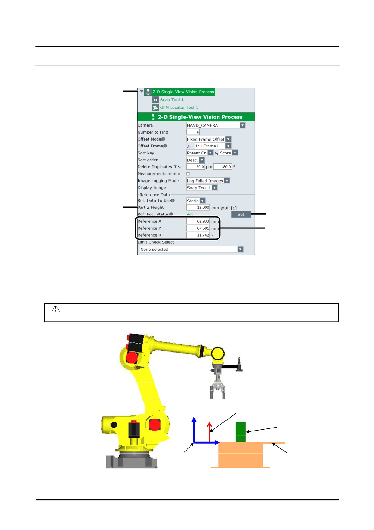
1. 2D SINGLE VIEW VISION PROCESS
Setup
1.3.3.3 Reference position setting
1
Select [2-D Single-View Vision Process] from the tree view.
1
2
4
5
2
In the text box for [Part Z Height], enter the height of the detected part of the workpiece.
When the XY plane of the offset frame is apart from the detected part of the workpiece, enter the
distance.
3
Click [SNAP] and snap the image, and click [FIND] to detect the workpiece.
CAUTION
Do not move the workpiece until the reference position setting is complete.
Part Z Height
Z
Workpi
X
Offset Frame
Table
Offset Frame and Part Z Height
36
B-83914EN-2/01
Setup
1. 2D SINGLE VIEW VISION PROCESS
4
Click the [Set] button for [Ref. Pos. Status]
1
5
Check that [Ref. Pos. Status] has become [Set] and that there are values for [Reference X],
[Reference Y] and [Reference R]. The values are the origin of the workpiece on the offset frame.
6
Click [SAVE] and click [END EDIT].
7
Move the robot to the position where work to the workpiece (e.g. gripping it).
For an example, refer to the sample program in Setup Edition Subsection 1.3.4, "Robot Program
Creation and Teaching". P[2] in line 11 is the position to work to the workpiece. Record the
current robot position to P[2], and reference position teaching is complete.
1.3.4
Robot Program Creation and Teaching
The sample program is shown below. A vision process "A" is used. Add
the
"VOFFSET, VR"
instruction to the movement statement.
1:
UFRAME_NUM=1 ;
2:
UTOOL_NUM=1 ;
3:
R[1:Notfound]=0
;
4:L P[1] 2000mm/sec FINE
;
5:
WAIT R[1] ;
6:
VISION RUN_FIND 'A'
;
7:
VISION GET_OFFSET 'A' VR[1] JMP LBL[100] ;
8:
;
9:
!Handling ;
10:L P[2] 2000mm/sec CNT100 VOFFSET,VR[1] Tool_Offset,PR[1]
;
11:L P[2] 500mm/sec FINE VOFFSET,VR[1]
;
12: CALL HAND_CLOSE
;
13:L P[2] 2000mm/sec CNT100 VOFFSET,VR[1] Tool_Offset,PR[3]
;
14:
!Handling ;
15:
JMP_LBL[900] ;
16:
;
17: LBL[100] ;
18: R[1:Notfound]=1
;
20:
;
21: LBL[900] ;
On line 4, move a camera to the snapping position. Execute a "WAIT" instruction to remove the
vibration of a camera on line 5. Execute the vision program [A] on line 6. Obtain the offset data on
line 7. Move the robot to approach position above the workpiece on line 10. Move the robot to grasp
position on line 11. Move the robot to the escape position after grasping the workpiece on line 13.
B-83914EN-2/01
37
1. 2D SINGLE VIEW VISION PROCESS
Setup
1.3.5
Robot Compensation Operation Check
Check that a placed workpiece on the table can be detected and handled accuracy.
• Place the workpiece on the reference position, find it and check the handling accuracy. If the
accuracy of the offset is low, set the reference position again.
• Move the workpiece without rotation, find it and check the handling accuracy. If the offset
accuracy is good on the reference position but it lows on the edge of the field of view, it is possible
that
‘Part Z Height’ is not set properly. Check the
[Part Z Height], refer to Setup Edition
Subsection 1.3.3.3, "Reference position setting".
• Rotate the workpiece, find it and check the handling accuracy. If the accuracy of the offset is good
on the non-rotated workpiece but it lows on rotated workpiece, it is possible that the offset frame or
the calibration grid frame is not set properly. When set the frames using the touch-up method with
a pointer tool, check the TCP setting is precise. Moreover, check the offset frame and calibration
grid frame are set precisely. If there is necessary, retry the camera calibration. If it is difficult to
retry the camera calibration, the ADJ_OFS may improve the situation without the re-set up the offset
frame and the calibration grid frame. ADJ_OFS is included in VISION SUPPORT TOOLS.
Refer to Setup Edition Subsection 8.1.6, "ADJ_OFS" in the "R-30iB Plus CONTROLLER iRVision
OPERATOR’S MANUAL (Reference) B-83914EN" for details.
• Depending on robot motion, a camera may vibrate at snap position. Execute "WAIT" instruction to
remove the possible vibration of a workpiece before the detection.
• Start with lower override of the robot to check that the logic of the program is correct. Next,
increase the override to check that the robot can operate continuously.
1.4
SETUP FOR TOOL OFFSET WITH FIXED CAMERA
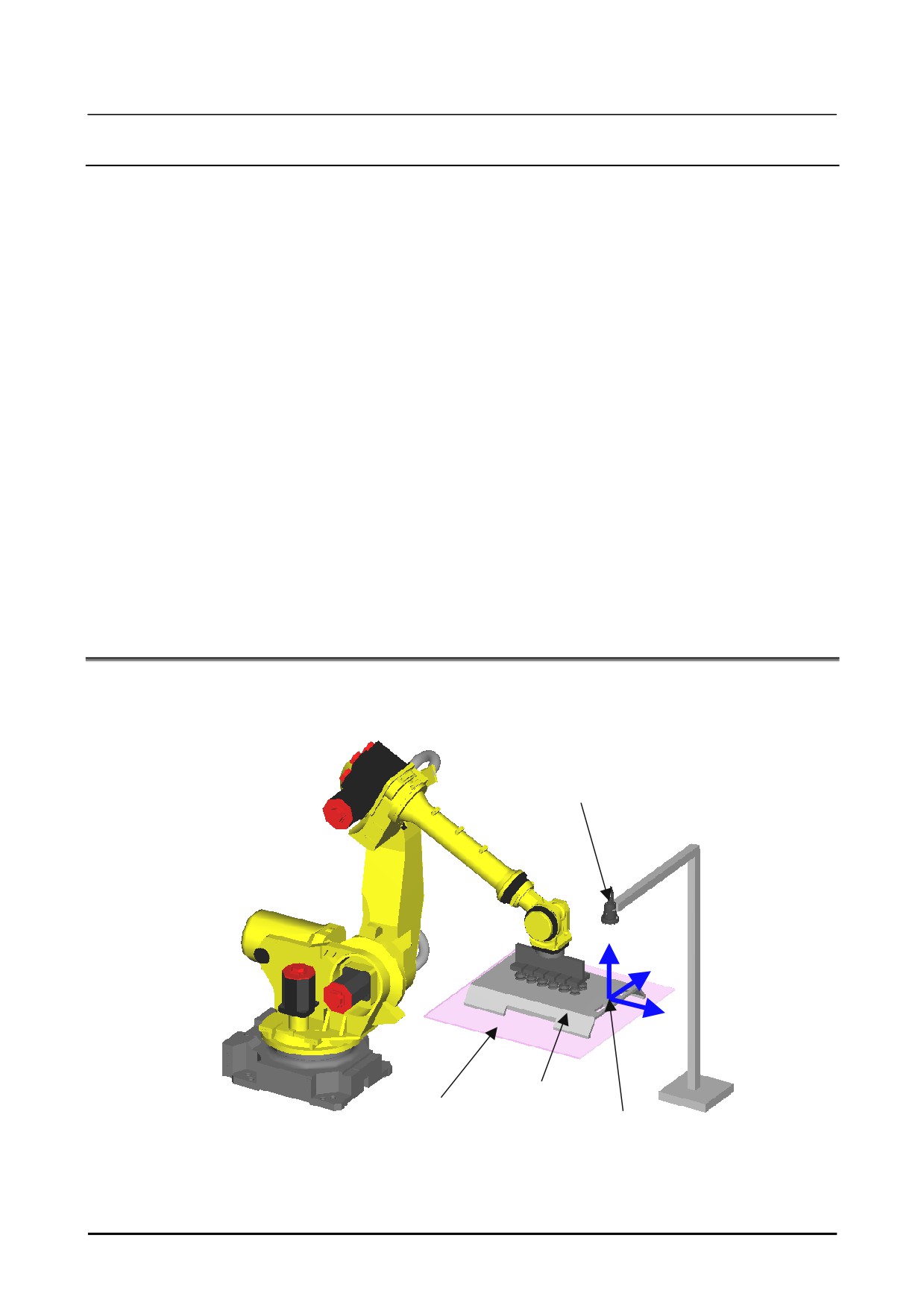
Snap a gripped workpiece by the robot with misaligned, and measure the amount of the misaligned. The
robot places the workpiece accurately to the specified position.
An example layout of "tool offset with fixed camera" is shown below:
Fixed camera
Z
Y
X
Workpiece
Workpiece deviation plane
Offset frame
Example of a layout for a tool offset with a fixed camera
38
B-83914EN-2/01
Setup
1. 2D SINGLE VIEW VISION PROCESS
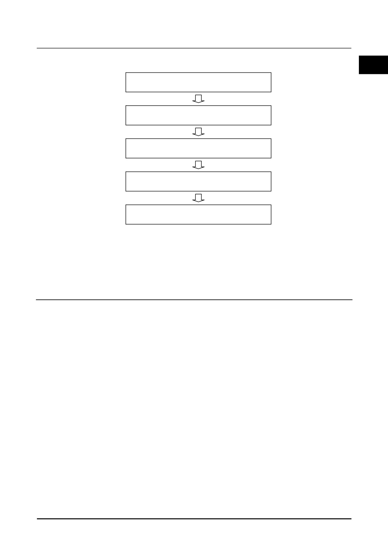
The setup procedures for the tool offset with thefixed camera is shown below:
1
1.
Camera Data Creation and Teaching
2.
Offset frame setting
3.
Vision process creation and teaching
4.
Robot program creation and teaching
5.
Robot compensation operation check
When create the vision system newly, perform all of the above procedures. When the position of the
camera is changed or the cameras are exchanged, redo the camera calibration in ‘1 Camera Data Creation
and Teaching’. When you need to add a new kind of workpiece, if a camera calibration has been already
done, the re-calibration of the camera is not needed. Perform ‘3 Vision process creation and teaching’
and ‘4 Robot program creation and teaching’.
1.4.1
Camera Data Creation and Teaching
Create a camera data and perform basic settings and calibration for the camera.
The Grid Pattern Calibration and the Robot-generated Grid Calibration can be used to calibrate a fixed
camera.
Grid Pattern Calibration
When the Grid Pattern Calibration is used for the calibration of tool offset, it is recommended to set the
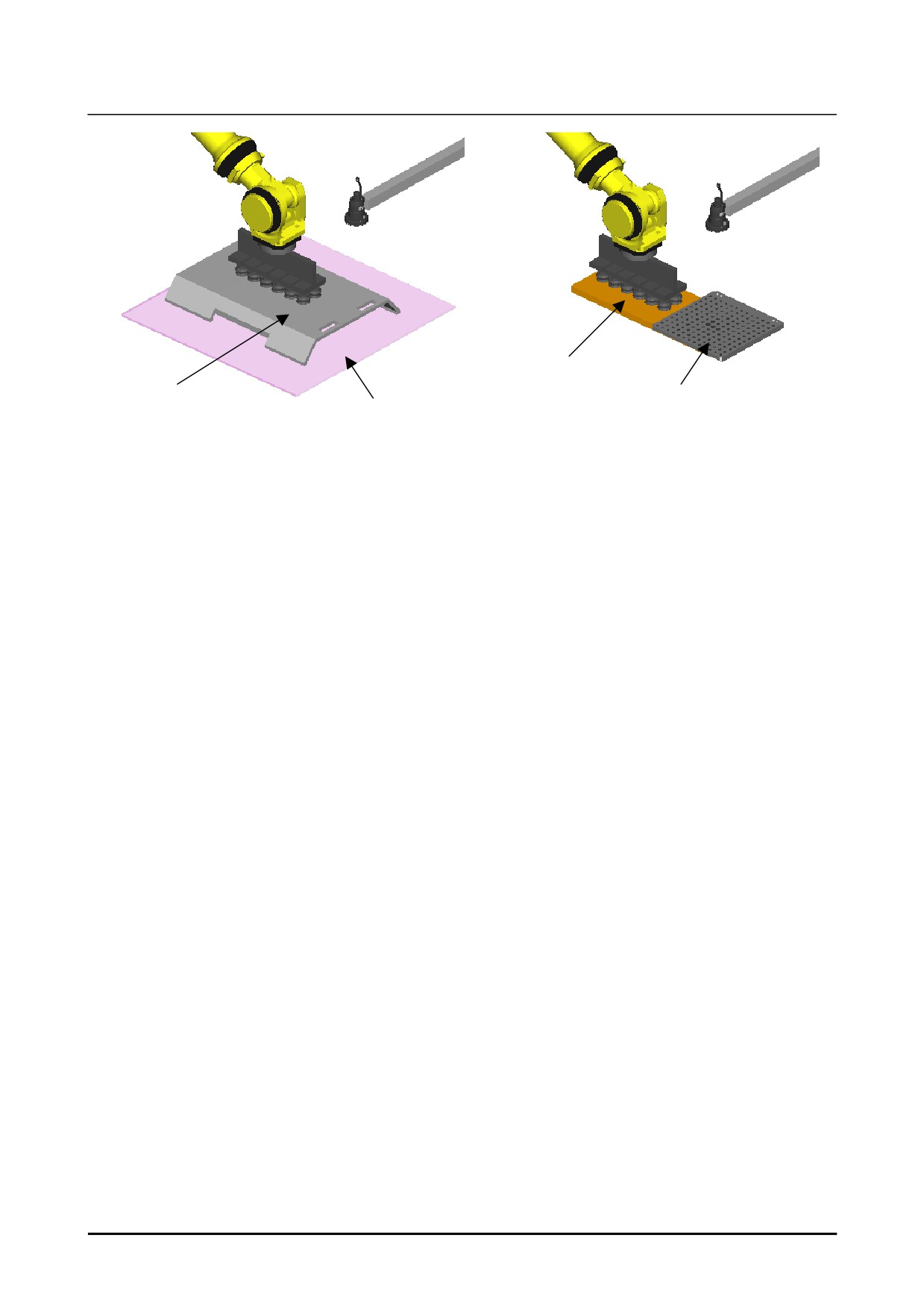
calibration grid on a dummy workpiece. In the following figures, the calibration grid is installed on the
same position as the measurement position of workpiece. Prepare a dummy workpiece so that it can be
gripped instead of an actual workpiece, and install the calibration grid on the dummy workpiece. By
using this method, setup of the offset frame can be simplified.
B-83914EN-2/01
39
1. 2D SINGLE VIEW VISION PROCESS
Setup
Dummy workpiece
Workpiece
Calibration grid
Workpiece deviation plane
How to attach a calibration grid
When install a calibration grid so that the XY plane of the calibration grid is parallel with the plane where
a workpiece moves, a setup of the offset frame becomes easy. For details of the grid frame calibration,
refer to Know-how Edition Section
2.1, "GRID PATTERN CALIBRATION WITH A FIXED
CAMERA".
Robot-generated Grid Calibration
When the robot-generated grid calibration is used for the calibration of tool offset, it is recommended to
attach a target mark to a dummy workpiece for calibration. Prepare a dummy workpiece so that it can
be gripped instead of an actual workpiece, and install the target mark on the dummy workpiece. By
using this method, setup of the offset frame can be simplified.
Set a target mark so that the XY plane
of the target mark is parallel with the plane on where a workpiece moves.
For details of the Robot-generated Grid Calibration, refer to Know-how Edition Section
2.3,
"ROBOT-GENERATED GRID CALIBRATION".
40
B-83914EN-2/01
Setup
1. 2D SINGLE VIEW VISION PROCESS
1.4.2
Offset Frame Setting
1
The offset frame is used for the calculation of the offset data in the 2D Single-view Vision Process. A
found position is outputted as a position on the offset frame. In the fixed frame offset, the offset frame
is set as a user frame, but in the tool offset, it is set as a tool frame.
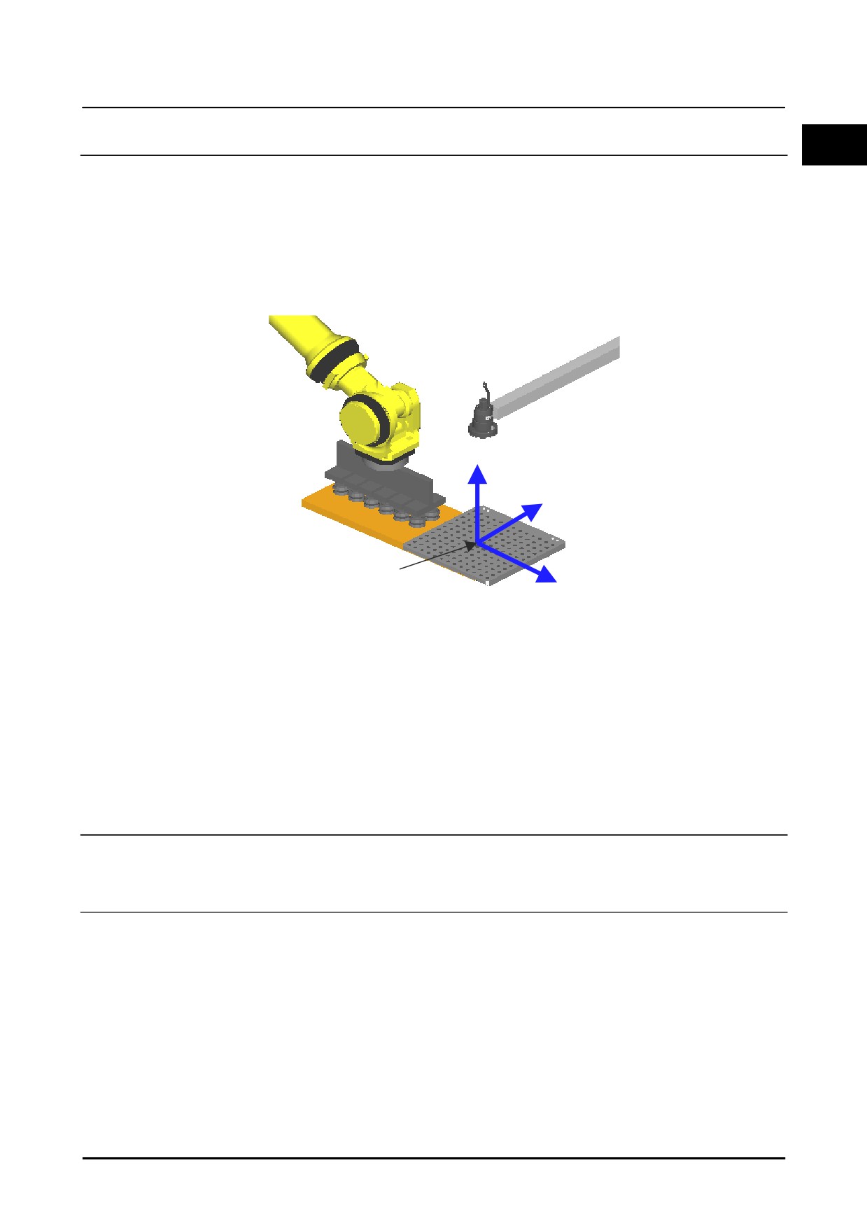
Set a tool frame so that the XY plane of the tool frame is parallel with the workpiece deviation plane.
When the Grid Pattern Calibration is used, if the XY plane of the tool frame that is set in Know-how
Edition Subsection 2.1.4, "Calibration" is parallel with the workpiece deviation plane, the tool frame can
be used as the offset frame.
Z
Y
Offset frame
( = Tool frame)
X
Offset frame setting
When the Robot-generated Grid Calibration is used, if the XY plane of the tool frame (UTool for work
space) that is set in Know-how Edition Subsection 2.3.8, "Measuring target position" is parallel with the
deviation plane of the workipece, the tool frame can be used as the offset frame. In this case, it is
recommended to copy the values of the UTool for work space to another tool frame number and specify it
as the offset frame number. For example, when the UTool for work space number is 9, copy the value
of the UTool for work space to arbitrary another tool frame numbers (for example, the tool frame number
is 1), and select the tool frame number as the offset frame.
1.4.3
Vision Process Creation and Teaching
Create a vision process and teach it. In addition, teach the locator tools and set the reference position.
1.4.3.1 Vision process creation
1
Create a vision process for [2-D Single-View Vision Process].
For details of the vision process creation, refer to Setup Edition Subsection 1.3.1.1, "Create" in the
"R-30iB Plus CONTROLLER iRVision OPERATOR’S MANUAL (Reference) B-83914EN".
2
On the vision data list screen, when the created vision process is selected and clicked [Edit], the
vision data edit screen will appear.
B-83914EN-2/01
41
1. 2D SINGLE VIEW VISION PROCESS
Setup
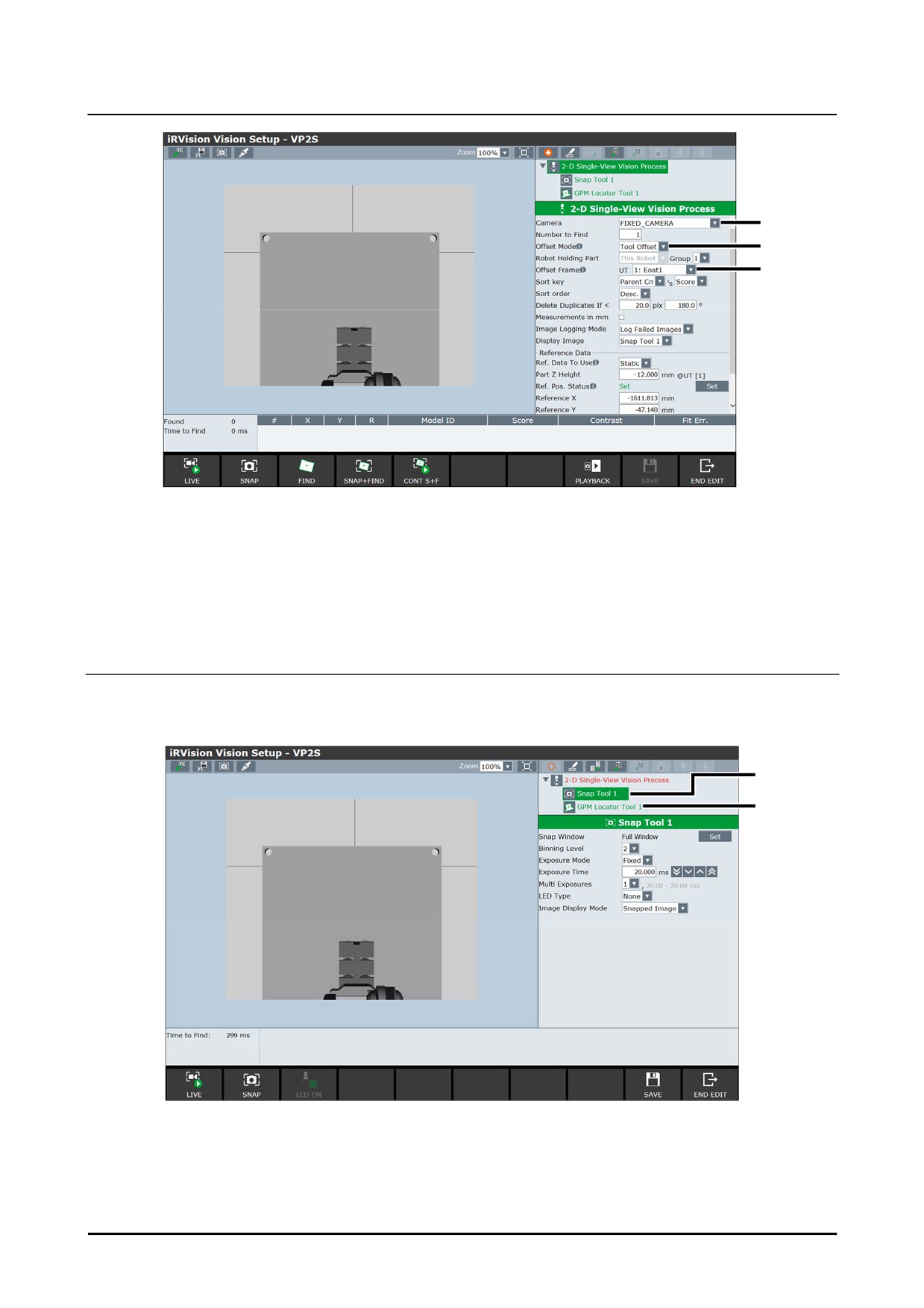
3
4
5
3
From the [Camera] drop-down box, select the camera data to be used.
Select the camera data specified in Setup Edition Subsection 1.4.1, "Camera Data Creation and
Teaching".
4
From the [Offset Mode] drop-down box, select [Tool Offset].
5
From the [Offset Frame] drop-down box, select the tool frame to set.
Select the frame number specified in Setup Edition Subsection 1.4.2, "Offset Frame Setting".
1.4.3.2 Command tool teaching
1
Place a workpiece in the field of view of the camera.
2
Move the robot to the measurement position where the workpiece can be snapped.
3
4
3
Set up the snap tool.
The snap tool is a tool that snaps images that are used to teach and find models. Set the snap
conditions such as the snap window and the exposure time. For details, refer to Setup Edition
Section
4.1, "SNAP TOOL" in the "R-30iB Plus CONTROLLER iRVision OPERATOR’S
MANUAL (Reference) B-83914EN".
42
B-83914EN-2/01