FANUC R-30iB Plus CONTROLLER, iRVision 2D Camera Application. OPERATOR'S MANUAL - page 1
SAFETY PRECAUTIONS
SAFETY PRECAUTIONS
This chapter describes the precautions which must be followed to ensure the safe use of the robot.
Before using the robot, be sure to read this chapter thoroughly.
For detailed functions of the robot operation, read the relevant operator's manual to understand fully its
specification.
For the safety of the operator and the system, follow all safety precautions when operating a robot and its
peripheral equipment installed in a work cell.
In addition, refer to the “FANUC Robot SAFETY HANDBOOK (B-80687EN)”.
1 DEFINITION OF USER
The user can be defined as follows.
Operator:
• Turns ON/OFF power to the robot
• Starts the robot program from the operator’s panel
Programmer:
• Operates the robot
• Teaches the robot inside the safety fence
Maintenance engineer:
• Operates the robot
• Teaches the robot inside the safety fence
• Performs maintenance (repair, adjustment, replacement)
-
Operator is not allowed to work in the safety fence.
-
Programmers and maintenance engineers are allowed to work in the safety fence. The work inside
the safety fence includes lifting, setting, teaching, adjustment, maintenance, etc.
-
To work inside the safety fence, the person must receive a professional training for the robot.
During the operation, programming, and maintenance of your robotic system, the programmer, operator,
and maintenance engineer should take additional care of their safety by wearing the following safety
items.
-
Adequate clothes for the operation
-
Safety shoes
-
A helmet
B-83914EN-2/01
s-1
SAFETY PRECAUTIONS
2 DEFINITION OF SAFETY NOTATIONS
To ensure the safety of users and prevent damage to the machine, this manual indicates each precaution on
safety with "WARNING" or "CAUTION" according to its severity. Supplementary information is indicated
by "NOTE". Read the contents of each "WARNING", "CAUTION" and "NOTE" before using the robot.
Symbol
Definitions
Used if hazard resulting in the death or serious injury of the user will
WARNING
be expected to occur if he or she fails to follow the approved
procedure.
Used if a hazard resulting in the minor or moderate injury of the user,
CAUTION
or equipment damage may be expected to occur if he or she fails to
follow the approved procedure.
Used if a supplementary explanation not related to any of WARNING
NOTE
and CAUTION is to be indicated.
• Check this manual thoroughly, and keep it handy for the future reference.
3 SAFETY OF THE USER
User safety is the primary safety consideration. Because it is very dangerous to enter the operating
space of the robot during automatic operation, adequate safety precautions must be observed.
The following lists the general safety precautions. Careful consideration must be made to ensure user
safety.
(1) Have the robot system users attend the training courses held by FANUC.
FANUC provides various training courses. Contact our sales office for details.
(2) Even when the robot is stationary, it is possible that the robot is still in a ready to move state, and is
waiting for a signal. In this state, the robot is regarded as still in motion. To ensure user safety,
provide the system with an alarm to indicate visually or aurally that the robot is in motion.
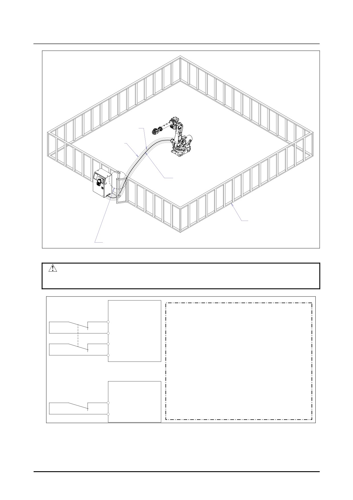
(3) Install a safety fence with a gate so that no user can enter the work area without passing through the
gate. Install an interlocking device, a safety plug, and so forth in the safety gate so that the robot is
stopped as the safety gate is opened.
The controller is designed to receive this interlocking signal of the door switch. When the gate
is opened and this signal received, the controller stops the robot (Please refer to "STOP
TYPE OF ROBOT" in "SAFETY PRECAUTIONS" for detail of stop type). For connection,
see Fig. 3 (b).
(4) Provide the peripheral equipment with appropriate earth (Class A, Class B, Class C, and Class D).
(5) Try to install the peripheral equipment outside the robot operating space.
(6) Draw an outline on the floor, clearly indicating the range of the robot operating space, including the
tools such as a hand.
(7) Install a mat switch or photoelectric switch on the floor with an interlock to a visual or aural alarm
that stops the robot when a user enters the work area.
(8) If necessary, install a safety lock so that no one except the user in charge can turn on the power of
the robot.
s-2
B-83914EN-2/01
SAFETY PRECAUTIONS
The circuit breaker installed in the controller is designed to disable anyone from turning it on
when it is locked with a padlock.
(9) When adjusting each peripheral equipment independently, be sure to turn off the power of the robot.
(10) Operators should be ungloved while manipulating the operator panel or teach pendant. Operation
with gloved fingers could cause an operation error.
(11) Programs, system variables, and other information can be saved on memory card or USB memories.
Be sure to save the data periodically in case the data is lost in an accident. (refer to Controller
OPERATOR’S MANUAL.)
(12) The robot should be transported and installed by accurately following the procedures recommended
by FANUC. Wrong transportation or installation may cause the robot to fall, resulting in severe
injury to workers.
(13) In the first operation of the robot after installation, the operation should be restricted to low speeds.
Then, the speed should be gradually increased to check the operation of the robot.
(14) Before the robot is started, it should be checked that no one is inside the safety fence. At the same
time, a check must be made to ensure that there is no risk of hazardous situations. If detected, such a
situation should be eliminated before the operation.
(15) When the robot is used, the following precautions should be taken. Otherwise, the robot and
peripheral equipment can be adversely affected, or workers can be severely injured.
- Avoid using the robot in a flammable environment.
- Avoid using the robot in an explosive environment.
- Avoid using the robot in an environment full of radiation.
- Avoid using the robot under water or at high humidity.
- Avoid using the robot to carry a person or animal.
- Avoid using the robot as a stepladder. (Never climb up on or hang from the robot.)
- Outdoor
(16) When connecting the peripheral equipment related to stop (safety fence etc.) and each signal
(external emergency, fence etc.) of robot, be sure to confirm the stop movement and do not take the
wrong connection.
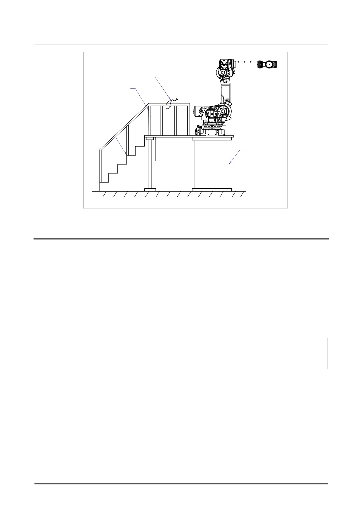
(17) When preparing footstep, please consider security for installation and maintenance work in high
place according to Fig. 3 (c). Please consider footstep and safety belt mounting position.
B-83914EN-2/01
s-3
SAFETY PRECAUTIONS
㻾㻼㻝
㻼㼡㼘㼟㼑㼏㼛㼐㼑㼞
㻾㻵㻛㻾㻻㻘㼄㻴㻮㻷㻘㼄㻾㻻㼀
㻾㻹㻝
㻹㼛㼠㼛㼞㻌㼜㼛㼣㼑㼞㻛㼎㼞㼍㼗㼑
㻱㻭㻾㼀㻴
Safety fence
Interlocking device and safety plug that are activated if the gate is opened.
Fig. 3 (a) Safety fence and safety gate
WARNING
When you close a fence, please confirm that there is not a person from all
directions of the robot.
㻰㼡㼍㼘㻌㼏㼔㼍㼕㼚
㻱㼙㼑㼞㼓㼑㼚㼏㼥㻌㼟㼠㼛㼜㻌㼎㼛㼍㼞㼐
㻔㻺㼛㼠㼑㻕㻌
㼛㼞㻌㻼㼍㼚㼑㼘㻌㼎㼛㼍㼞㼐㻌
㻌
㻌㻱㻭㻿㻝
㻌
㻲㼛㼞㻌㼠㼔㼑㻌㻾㻙㻟㻜i㻮㻘㻌㼠㼔㼑㻌㻾㻙㻟㻜i㻮㻌㻹㼍㼠㼑㻌㻘㻌
㻌㻱㻭㻿㻝㻝
㼠㼔㼑㻌㻾㻙㻟㻜i㻮㻌㻼㼘㼡㼟㻘㻌㼠㼔㼑㻌㻾㻙㻟㻜i㻮㻌㻹㼍㼠㼑㻌㻼㼘㼡㼟㻌
㼀㼑㼞㼙㼕㼚㼍㼘㼟㻌㻱㻭㻿㻝㻘㻱㻭㻿㻝㻝㻘㻱㻭㻿㻞㻘㻱㻭㻿㻞㻝㻌㼍㼞㼑㻌㼜㼞㼛㼢㼕㼐㼑㼐㻌㼛㼚㻌㼠㼔㼑㻌 㻌
㻌㻱㻭㻿㻞
㼑㼙㼑㼞㼓㼑㼚㼏㼥㻌㼟㼠㼛㼜㻌㼎㼛㼍㼞㼐㻚㻌
㻌㻱㻭㻿㻞㻝
㻌
㻾㼑㼒㼑㼞㻌㼠㼛㻌㼠㼔㼑㻌㻟㻚㻌㻱㻸㻱㻯㼀㻾㻵㻯㻭㻸㻌㻯㻻㻺㻺㻯㻱㼀㻵㻻㻺㻿㻌㼛㼒㻌㻵㻵㻚㻌㻯㻻㻺㻺㻱㻯㼀㻵㻻㻺㻌㼕㼚㻌
㻾㻙㻟㻜i㻮㻛㻾㻙㻟㻜i㻮㻌 㻼㼘㼡㼟㻌 㻯㻻㻺㼀㻾㻻㻸㻸㻱㻾㻌 㻹㻭㻵㻺㼀㻱㻺㻭㻺㻯㻱㻌 㻹㻭㻺㼁㻭㻸㻌
㻔㻮㻙㻤㻟㻝㻥㻡㻱㻺㻕㻌㼛㼞㻌
㻾㻙㻟㻜i㻮㻌 㻹㼍㼠㼑㻛㻾㻙㻟㻜i㻮㻌 㻹㼍㼠㼑㻌 㻼㼘㼡㼟㻌 㻯㻻㻺㼀㻾㻻㻸㻸㻱㻾㻌 㻹㻭㻵㻺㼀㻱㻺㻭㻺㻯㻱㻌
㻹㻭㻺㼁㻭㻸㻌㻔㻮㻙㻤㻟㻡㻞㻡㻱㻺㻕㻌㼒㼛㼞㻌㼐㼑㼠㼍㼕㼘㼟㻚㻌
㻿㼕㼚㼓㼘㼑㻌㼏㼔㼍㼕㼚
㻼㼍㼚㼑㼘㻌㼎㼛㼍㼞㼐
㻌
㻌㻲㻱㻺㻯㻱㻝
㻌㻲㻱㻺㻯㻱㻞
Fig. 3 (b) Connection diagram for the signal of safety fence
s-4
B-83914EN-2/01
SAFETY PRECAUTIONS
㻴㼛㼛㼗㻌㼒㼛㼞㻌㼟㼍㼒㼑㼠㼥㻌㼎㼑㼘㼠
㻲㼑㼚㼏㼑
㻿㼠㼑㼜㼟
㼀㼞㼑㼟㼠㼘㼑
㻼㼑㼐㼑㼟㼠㼍㼘
㼒㼛㼞㻌㼙㼍㼕㼚㼠㼑㼚㼍㼚㼏㼑
Fig. 3 (c) Pedestal for maintenance
3.1
SAFETY OF THE OPERATOR
An operator refers to a person who turns on and off the robot system and starts a robot program from, for
example, the operator panel during daily operation.
Operators cannot work inside of the safety fence.
(1) If the robot does not need to be operated, turn off the robot controller power or press the
EMERGENCY STOP button during working.
(2) Operate the robot system outside the operating space of the robot.
(3) Install a safety fence or safety door to avoid the accidental entry of a person other than an operator in
charge or keep operator out from the hazardous place.
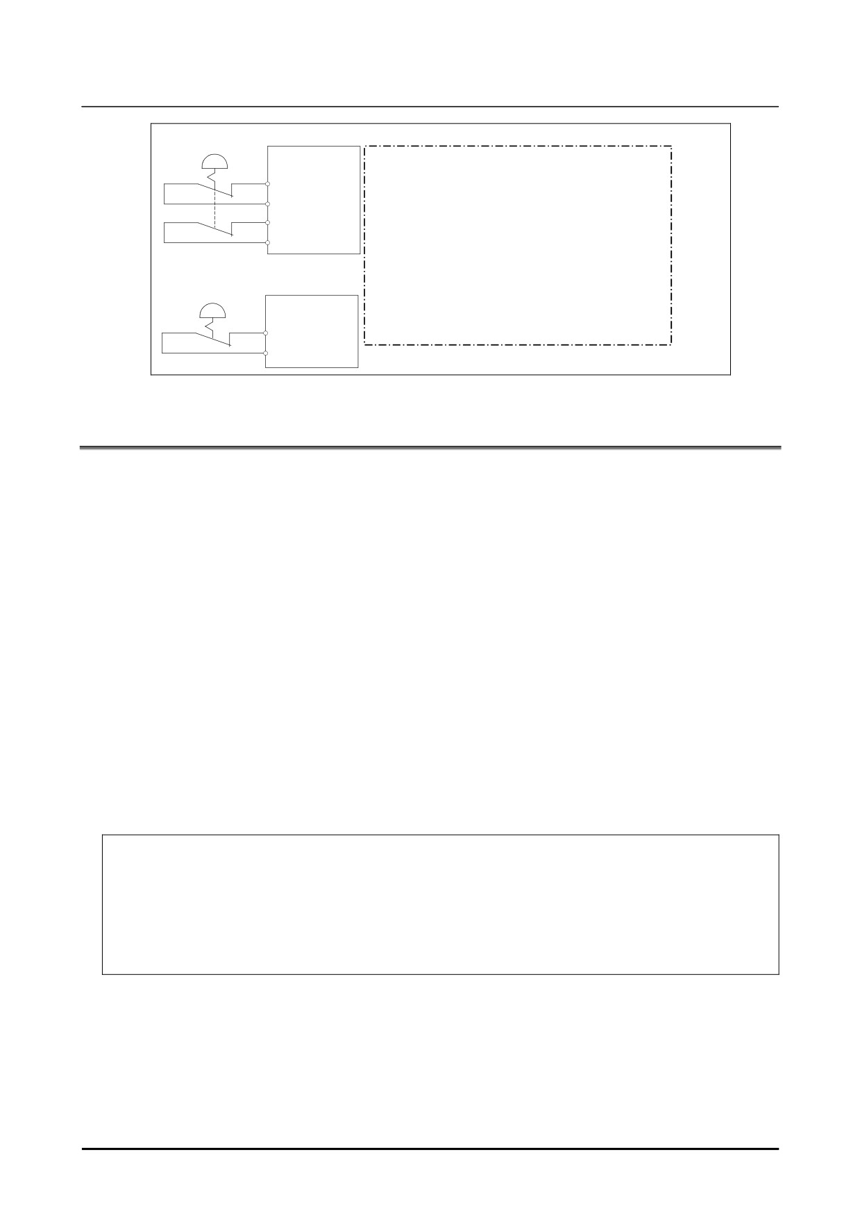
(4) Install one or more necessary quantity of EMERGENCY STOP button(s) within the operator’s reach
in appropriate location(s) based on the system layout.
The robot controller is designed to be connected to an external EMERGENCY STOP button.
With this connection, the controller stops the robot operation
(Please refer to "STOP TYPE
OF ROBOT" in "SAFETY PRECAUTIONS" for detail of stop type) when the external
EMERGENCY STOP button is pressed. See the diagram below for connection.
B-83914EN-2/01
s-5
SAFETY PRECAUTIONS
㻰㼡㼍㼘㻌㼏㼔㼍㼕㼚
㻱㼤㼠㼑㼞㼚㼍㼘㻌㼟㼠㼛㼜㻌㼎㼡㼠㼠㼛㼚
㻱㼙㼑㼞㼓㼑㼚㼏㼥㻌㼟㼠㼛㼜㻌㼎㼛㼍㼞㼐
㻔㻺㼛㼠㼑㻕㻌
㼛㼞㻌㻼㼍㼚㼑㼘㻌㼎㼛㼍㼞㼐㻌
㻯㼛㼚㼚㼑㼏㼠㻌㻱㻱㻿㻝㻌㼍㼚㼐㻌㻱㻱㻿㻝㻝㻘㻌㻱㻱㻿㻞㻌㼍㼚㼐㻌㻱㻱㻿㻞㻝㻚㻌 㻌
㻌㻱㻱㻿㻝
㻌
㻲㼛㼞㻌㼠㼔㼑㻌㻾㻙㻟㻜i㻮㻘㻌㼠㼔㼑㻌㻾㻙㻟㻜i㻮㻌㻹㼍㼠㼑㻘㻌
㻌㻱㻱㻿㻝㻝
㼠㼔㼑㻌㻾㻙㻟㻜i㻮㻌㻼㼘㼡㼟㻘㻌㼠㼔㼑㻌㻾㻙㻟㻜i㻮㻌㻹㼍㼠㼑㻌㻼㼘㼡㼟㻌
㻌㻱㻱㻿㻞
㻌
㻱㻱㻿㻝㻘㻌㻱㻱㻿㻝㻝㻘㻌㻱㻱㻿㻞㻘㻌㻱㻱㻿㻞㻝㻌㼍㼞㼑㻌㼛㼚㻌㼠㼔㼑㻌㼑㼙㼑㼞㼓㼑㼚㼏㼥㻌㼟㼠㼛㼜㻌㼎㼛㼍㼞㼐㻚㻌
㻌㻱㻱㻿㻞㻝
㻌
㻾㼑㼒㼑㼞㻌㼠㼛㻌㼠㼔㼑㻌㻟㻚㻌㻱㻸㻱㻯㼀㻾㻵㻯㻭㻸㻌㻯㻻㻺㻺㻯㻱㼀㻵㻻㻺㻿㻌㼛㼒㻌㻵㻵㻚㻌㻯㻻㻺㻺㻱㻯㼀㻵㻻㻺㻌㼕㼚㻌
㻾㻙㻟㻜i㻮㻛㻾㻙㻟㻜i㻮㻌 㻼㼘㼡㼟㻌 㻯㻻㻺㼀㻾㻻㻸㻸㻱㻾㻌 㻹㻭㻵㻺㼀㻱㻺㻭㻺㻯㻱㻌 㻹㻭㻺㼁㻭㻸㻌
㻿㼕㼚㼓㼘㼑㻌㼏㼔㼍㼕㼚
㻔㻮㻙㻤㻟㻝㻥㻡㻱㻺㻕㻌㼛㼞㻌
㻱㼤㼠㼑㼞㼚㼍㼘㻌㼟㼠㼛㼜㻌㼎㼡㼠㼠㼛㼚
㻾㻙㻟㻜i㻮㻌 㻹㼍㼠㼑㻛㻾㻙㻟㻜i㻮㻌 㻹㼍㼠㼑㻌 㻼㼘㼡㼟㻌 㻯㻻㻺㼀㻾㻻㻸㻸㻱㻾㻌 㻹㻭㻵㻺㼀㻱㻺㻭㻺㻯㻱㻌
㻼㼍㼚㼑㼘㻌㼎㼛㼍㼞㼐㻌
㻹㻭㻺㼁㻭㻸㻌㻔㻮㻙㻤㻟㻡㻞㻡㻱㻺㻕㻌㼒㼛㼞㻌㼐㼑㼠㼍㼕㼘㼟㻚㻌
㻌
㻌㻱㻹㻳㻵㻺㻝
㻌㻱㻹㻳㻵㻺㻞
Fig. 3.1 Connection diagram for external emergency stop button
3.2
SAFETY OF THE PROGRAMMER
While teaching the robot, the operator may need to enter the robot operation area. The programmer
must ensure the safety especially.
(1) Unless it is specifically necessary to enter the robot operating space, carry out all tasks outside the
operating space.
(2) Before teaching the robot, check that the robot and its peripheral equipment are all in the normal
operating condition.
(3) If it is inevitable to enter the robot operating space to teach the robot, check the locations, settings,
and other conditions of the safety devices
(such as the EMERGENCY STOP button, the
DEADMAN switch on the teach pendant) before entering the area.
(4) The programmer must be extremely careful not to let anyone else enter the robot operating space.
(5) Programming should be done outside the area of the safety fence as far as possible. If programming
needs to be done inside the safety fence, the programmer should take the following precautions:
- Before entering the area of the safety fence, ensure that there is no risk of dangerous situations
in the area.
- Be prepared to press the emergency stop button whenever necessary.
- Robot motions should be made at low speeds.
- Before starting programming, check the whole robot system status to ensure that no remote
instruction to the peripheral equipment or motion would be dangerous to the user.
Our operator panel is provided with an emergency stop button and a key switch (mode switch) for selecting the
automatic operation (AUTO) and the teach modes (T1 and T2). Before entering the inside of the safety fence for
the purpose of teaching, set the switch to a teach mode, remove the key from the mode switch to prevent other
people from changing the operation mode carelessly, then open the safety gate. If the safety gate is opened with
the automatic operation set, the robot stops (Please refer to "STOP TYPE OF ROBOT" in "SAFETY
PRECAUTIONS" for detail of stop type). After the switch is set to a teach mode, the safety gate is disabled. The
programmer should understand that the safety gate is disabled and is responsible for keeping other people from
entering the inside of the safety fence.
s-6
B-83914EN-2/01
SAFETY PRECAUTIONS
Our teach pendant is provided with a DEADMAN switch as well as an emergency stop button. These button and
switch function as follows:
(1) Emergency stop button: Causes the stop of the robot (Please refer to "STOP TYPE OF ROBOT" in
"SAFETY PRECAUTIONS" for detail of stop type) when pressed.
(2) DEADMAN switch: Functions differently depending on the teach pendant enable/disable switch setting
status.
(a)
Enable: Servo power is turned off when the operator releases the DEADMAN switch or when the
operator presses the switch strongly.
(b)
Disable: The DEADMAN switch is disabled.
(Note) The DEADMAN switch is provided to stop the robot when the operator releases the teach pendant or
presses the pendant strongly in case of emergency. The R-30iB/R-30iB Mate/R-30iB Plus/R-30iB
Mate Plus employs a 3-position DEADMAN switch, which allows the robot to operate when the
3-position DEADMAN switch is pressed to its intermediate point. When the operator releases the
DEADMAN switch or presses the switch strongly, the robot stops immediately.
The operator’s intention of starting teaching is determined by the controller through the dual operation of setting the
teach pendant enable/disable switch to the enable position and pressing the DEADMAN switch. The operator
should make sure that the robot could operate in such conditions and be responsible in carrying out tasks safely.
Based on the risk assessment by FANUC, number of operation of DEADMAN SW should not exceed about 10000
times per year.
The teach pendant, operator panel, and peripheral equipment interface send each robot start signal. However the
validity of each signal changes as follows depending on the mode switch and the DEADMAN switch of the operator
panel, the teach pendant enable switch and the remote condition on the software.
Software
Teach pendant
Peripheral
Mode
remote
Teach pendant
Operator panel
enable switch
equipment
condition
Local
Not allowed
Not allowed
Not allowed
On
AUTO
Remote
Not allowed
Not allowed
Not allowed
mode
Local
Not allowed
Allowed to start
Not allowed
Off
Remote
Not allowed
Not allowed
Allowed to start
Local
Allowed to start
Not allowed
Not allowed
On
T1, T2
Remote
Allowed to start
Not allowed
Not allowed
mode
Local
Not allowed
Not allowed
Not allowed
Off
Remote
Not allowed
Not allowed
Not allowed
T1,T2 mode: DEADMAN switch is effective.
(6) To start the system using the operator box or operator panel, make certain that nobody is the robot
operating space area and that there are no abnormalities in the robot operating space.
(7) When a program is completed, be sure to carry out a test operation according to the following
procedure.
(a) Run the program for at least one operation cycle in the single step mode at low speed.
(b) Run the program for at least one operation cycle in continuous operation at low speed.
(c) Run the program for one operation cycle in continuous operation at the intermediate speed and
check that no abnormalities occur due to a delay in timing.
(d) Run the program for one operation cycle in continuous operation at the normal operating speed
and check that the system operates automatically without trouble.
(e) After checking the completeness of the program through the test operation above, execute it in
the automatic operation.
(8) While operating the system in the automatic operation, the programmer should leave the safety
fence.
B-83914EN-2/01
s-7
SAFETY PRECAUTIONS
3.3
SAFETY OF THE MAINTENANCE ENGINEER
For the safety of maintenance engineer personnel, pay utmost attention to the following.
(1) During operation, never enter the robot operating space.
(2) A hazardous situation may arise when the robot or the system, are kept with their power-on during
maintenance operations. Therefore, for any maintenance operation, the robot and the system should
be put into the power-off state. If necessary, a lock should be in place in order to prevent any other
person from turning on the robot and/or the system. In case maintenance needs to be executed in the
power-on state, the emergency stop button must be pressed as far as possible.
(3) If it becomes necessary to enter the robot operating space while the power is on, press the emergency
stop button on the operator box or operator panel, or the teach pendant before entering the range.
The maintenance worker must indicate that maintenance work is in progress and be careful not to
allow other people to operate the robot carelessly.
(4) When entering the area enclosed by the safety fence, the worker must check the whole robot system
in order to make sure no dangerous situations exist. In case the worker needs to enter the safety area
whilst a dangerous situation exists, extreme care must be taken, and whole robot system status must
be carefully monitored.
(5) Before the maintenance of the pneumatic system is started, the supply pressure should be shut off
and the pressure in the piping should be reduced to zero.
(6) Before the start of maintenance work, check that the robot and its peripheral equipment are all in the
normal operating condition.
(7) Do not operate the robot in the automatic operation while anybody is in the robot operating space.
(8) When you maintain the robot alongside a wall or instrument, or when multiple users are working
nearby, make certain that their escape path is not obstructed.
(9) When a tool is mounted on the robot, or when any movable device other than the robot is installed,
such as belt conveyor, pay careful attention to its motion.
(10) If necessary, have a user who is familiar with the robot system stand beside the operator panel and
observe the work being performed. If any danger arises, the user should be ready to press the
EMERGENCY STOP button at any time.
(11) When replacing a part, please contact your local FANUC representative. If a wrong procedure is
followed, an accident may occur, causing damage to the robot and injury to the user.
(12) When replacing or reinstalling components, take care to prevent foreign material from entering the
system.
(13) When handling each unit or printed circuit board in the controller during inspection, turn off the
circuit breaker to protect against electric shock.
If there are two cabinets, turn off the both circuit breaker.
(14) A part should be replaced with a part recommended by FANUC. If other parts are used, malfunction
or damage would occur. Especially, a fuse that is not recommended by FANUC should not be used.
Such a fuse may cause a fire.
(15) When restarting the robot system after completing maintenance work, make sure in advance that
there is no person in the operating space and that the robot and the peripheral equipment are not
abnormal.
(16) When a motor or brake is removed, the robot arm should be supported with a crane or other
equipment beforehand so that the arm would not fall during the removal.
(17) Whenever grease is spilled on the floor, it should be removed as quickly as possible to prevent
dangerous falls.
(18) The following parts are heated. If a maintenance user needs to touch such a part in the heated state,
the user should wear heat-resistant gloves or use other protective tools.
- Servo motor
- Inside the controller
- Reducer
- Gearbox
s-8
B-83914EN-2/01
SAFETY PRECAUTIONS
- Wrist unit
(19) Maintenance should be done under suitable light. Care must be taken that the light would not cause
any danger.
(20) When a motor, reducer, or other heavy load is handled, a crane or other equipment should be used to
protect maintenance workers from excessive load. Otherwise, the maintenance workers would be
severely injured.
(21) The robot should not be stepped on or climbed up during maintenance. If it is attempted, the robot
would be adversely affected. In addition, a misstep can cause injury to the worker.
(22) When performing maintenance work in high place, secure a footstep and wear safety belt.
(23) After the maintenance is completed, spilled oil or water and metal chips should be removed from the
floor around the robot and within the safety fence.
(24) When a part is replaced, all bolts and other related components should put back into their original
places. A careful check must be given to ensure that no components are missing or left not mounted.
(25) In case robot motion is required during maintenance, the following precautions should be taken :
- Foresee an escape route. And during the maintenance motion itself, monitor continuously the
whole robot system so that your escape route will not become blocked by the robot, or by peripheral
equipment.
- Always pay attention to potentially dangerous situations, and be prepared to press the emergency
stop button whenever necessary.
(26) The robot should be periodically inspected. (Refer to the robot mechanical manual and controller
maintenance manual.) A failure to do the periodical inspection can adversely affect the performance
or service life of the robot and may cause an accident
(27) After a part is replaced, a test execution should be given for the robot according to a predetermined
method. (See TESTING section of “Controller operator’s manual”.) During the test execution, the
maintenance worker should work outside the safety fence.
4 SAFETY OF THE TOOLS AND
PERIPHERAL EQUIPMENT
4.1
PRECAUTIONS IN PROGRAMMING
(1) Use a limit switch or other sensor to detect a dangerous condition and, if necessary, design the
program to stop the robot when the sensor signal is received.
(2) Design the program to stop the robot when an abnormality occurs in any other robots or peripheral
equipment, even though the robot itself is normal.
(3) For a system in which the robot and its peripheral equipment are in synchronous motion, particular
care must be taken in programming so that they do not interfere with each other.
(4) Provide a suitable interface between the robot and its peripheral equipment so that the robot can
detect the states of all devices in the system and can be stopped according to the states.
4.2
PRECAUTIONS FOR MECHANISM
(1) Keep the component cells of the robot system clean, operate the robot where insulated from the
influence of oil, water, and dust.
(2) Don’t use unconfirmed liquid for cutting fluid and cleaning fluid.
(3) Adopt limit switches or mechanical stoppers to limit the robot motion, and avoid the robot from
collisions against peripheral equipment or tools.
(4) Observe the following precautions about the mechanical unit cables. Failure to follow precautions
may cause problems.
•
Use mechanical unit cable that have required user interface.
B-83914EN-2/01
s-9
SAFETY PRECAUTIONS
•
Do not add user cable or hose to inside of the mechanical unit.
•
Please do not obstruct the movement of the mechanical unit when cables are added to outside
of mechanical unit.
•
In the case of the model that a cable is exposed, please do not perform remodeling (Adding a
protective cover and fix an outside cable more) obstructing the behavior of the outcrop of the
cable.
•
When installing user peripheral equipment on the robot mechanical unit, please pay attention
that the device does not interfere with the robot itself.
(5)
The frequent power-off stop for the robot during operation causes the trouble of the robot. Please
avoid the system construction that power-off stop would be operated routinely. (Refer to bad case
example.) Please perform power-off stop after reducing the speed of the robot and stopping it by
hold stop or cycle stop when it is not urgent. (Please refer to "STOP TYPE OF ROBOT" in
"SAFETY PRECAUTIONS" for detail of stop type.)
(Bad case example)
•
Whenever poor product is generated, a line stops by emergency stop and power-off of the robot
is incurred.
•
When alteration is necessary, safety switch is operated by opening safety fence and power-off
stop is incurred for the robot during operation.
•
An operator pushes the emergency stop button frequently, and a line stops.
•
An area sensor or a mat switch connected to safety signal operates routinely and power-off stop
is incurred for the robot.
•
Power-off stop is regularly incurred due to an inappropriate setting for Dual Check Safety
(DCS).
(6)
Power-off stop of Robot is executed when collision detection alarm (SRVO-050) etc. occurs. Please
try to avoid unnecessary power-off stops. It may cause the trouble of the robot, too. So remove the
causes of the alarm.
5 SAFETY OF THE ROBOT MECHANICAL
UNIT
5.1
PRECAUTIONS IN OPERATION
(1) When operating the robot in the jog mode, set it at an appropriate speed so that the operator can
manage the robot in any eventuality.
(2) Before pressing the jog key, be sure you know in advance what motion the robot will perform in the
jog mode.
5.2
PRECAUTIONS IN PROGRAMMING
(1) When the operating spaces of robots overlap, make certain that the motions of the robots do not
interfere with each other.
(2) Be sure to specify the predetermined work origin in a motion program for the robot and program the
motion so that it starts from the origin and terminates at the origin. Make it possible for the operator
to easily distinguish at a glance that the robot motion has terminated.
5.3
PRECAUTIONS FOR MECHANISMS
(1)
Keep the robot operation area clean, and operate the robot in an environment free of grease, water,
and dust.
s-10
B-83914EN-2/01
SAFETY PRECAUTIONS
5.4
PROCEDURE TO MOVE ARM WITHOUT DRIVE POWER
IN EMERGENCY OR ABNORMAL SITUATIONS
For emergency or abnormal situations (e.g. persons trapped in or pinched by the robot), brake release unit
can be used to move the robot axes without drive power.
Please refer to controller maintenance manual and mechanical unit operator’s manual for using method of
brake release unit and method of supporting robot.
6 SAFETY OF THE END EFFECTOR
6.1
PRECAUTIONS IN PROGRAMMING
(1) To control the pneumatic, hydraulic and electric actuators, carefully consider the necessary time
delay after issuing each control command up to actual motion and ensure safe control.
(2) Provide the end effector with a limit switch, and control the robot system by monitoring the state of
the end effector.
7 STOP TYPE OF ROBOT (R-30iB, R-30iB
Mate)
There are following four types of Stopping Robot.
Power-Off Stop (Category 0 following IEC 60204-1)
Servo power is turned off, and the robot stops immediately. Servo power is turned off when the robot is
moving, and the motion path of the deceleration is uncontrolled.
“Power-Off stop” performs following processing.
• An alarm is generated, and then the servo power turns off. Instantly the robot stops.
• Execution of the program is paused.
Frequent Power-Off stop of the robot during operation can cause mechanical problems of the robot.
Avoid system designs that require routine or frequent Power-Off stop conditions.
Controlled stop (Category 1 following IEC 60204-1)
The robot is decelerated until it stops, and servo power is turned off.
“Controlled stop” performs following processing.
• The alarm "SRVO-199 Controlled stop" occurs along with a decelerated stop. The program
execution is paused.
• An alarm is generated, and then the servo power turns off.
Smooth stop (Category 1 following IEC 60204-1)
The robot is decelerated until it stops, and servo power is turned off.
“Smooth stop” performs following processing.
• The alarm "SRVO-289 Smooth Stop" occurs along with a decelerated stop. The program
execution is paused.
• An alarm is generated, and then the servo power turns off.
• In Smooth stop, the robot decelerates until it stops with the deceleration time shorter than Controlled
stop.
B-83914EN-2/01
s-11

SAFETY PRECAUTIONS
Hold (Category 2 following IEC 60204-1)
The robot is decelerated until it stops, and servo power remains on.
“Hold” performs following processing.
• The robot operation is decelerated until it stops. Execution of the program is paused.
WARNING
1
The stopping distance and time of Controlled stop and Smooth stop are longer
than those of Power-Off stop. A risk assessment for the whole robot system
which takes into consideration the increased stopping distance and stopping
time is necessary when Controlled stop or Smooth Stop is used. Please refer to
the operator's manual of a particular robot model for the data of stopping
distance and time.
2
In multi arm system, the longest stopping distance and time of Controlled Stop
or Smooth Stop among each robot are adopted as those for the system. A risk
assessment for the whole robot system which takes into consideration a
possibility that the stopping distance and time increase, is necessary on the
multi arm system.
3
In the system which has extended axis, the longer stopping distance and time of
Controlled Stop or Smooth Stop among robot and extended axis are adopted as
those for the system. A risk assessment for the whole robot system which takes
into consideration a possibility that the stopping distance and time increase, is
necessary on the system which has extended axis. Please refer to the extended
axis setup procedure of the controller operator’s manual for considering the
stopping distance and time of the extended axis.
4
When Smooth stop occurs during deceleration by Controlled stop, the stop type
of robot is changed to Power-Off Stop.
When Smooth stop occurs during deceleration by Hold, the stop type of robot is
changed to Power-Off Stop.
5
In case of Controlled stop or Smooth Stop, motor power shutdown is delayed for
a maximum of 2 seconds. In this case, a risk assessment for the whole robot
system is necessary, including the 2 seconds delay.
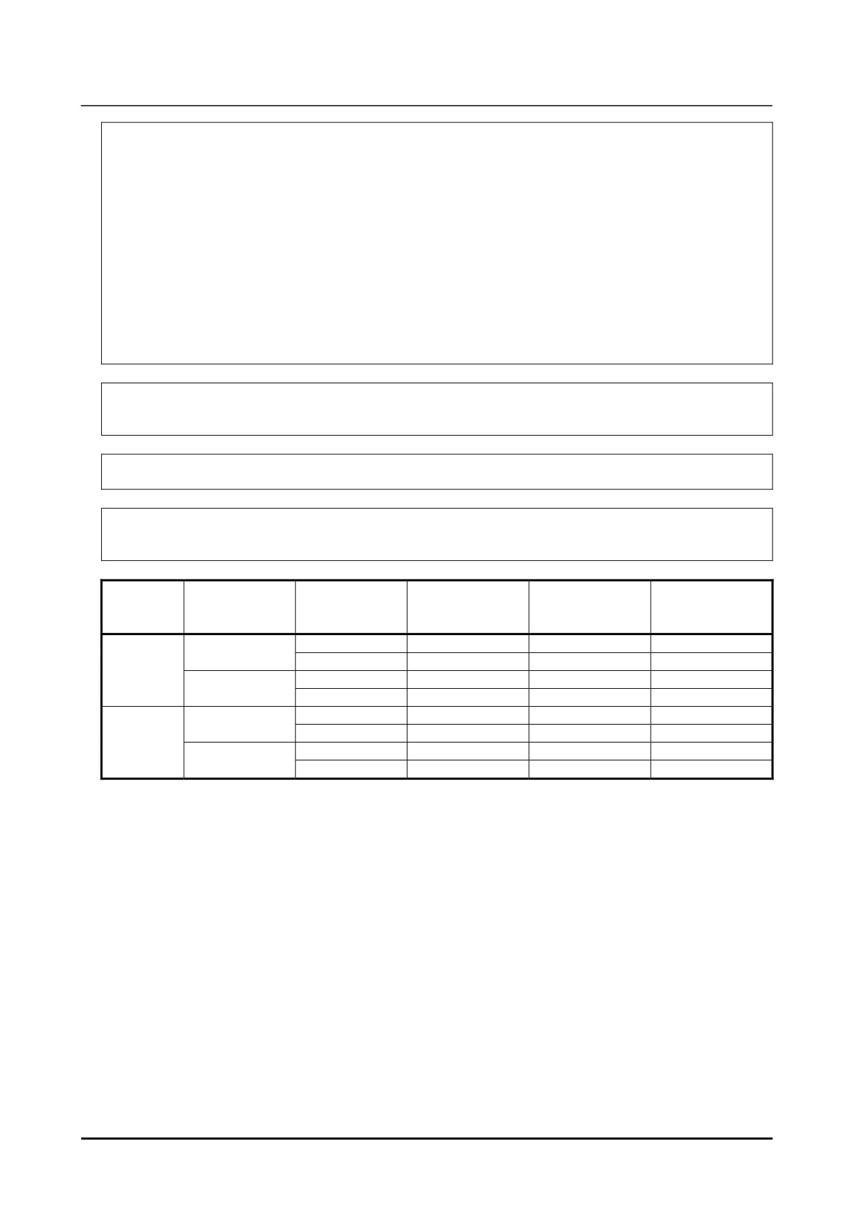
When the emergency stop button is pressed or the FENCE is open, the stop type of robot is Power-Off
stop, Controlled stop, or Smooth stop. The configuration of stop type for each situation is called stop
pattern. The stop pattern is different according to the option configuration.
There are the following 3 Stop patterns.
Emergency
External
Stop
Deadman
Mode
stop
Emergency
FENCE open
SVOFF input
pattern
switch (*)
button
stop
AUTO
P-Stop
P-Stop
C-Stop
C-Stop
-
A
T1
P-Stop
P-Stop
-
C-Stop
P-Stop
T2
P-Stop
P-Stop
-
C-Stop
P-Stop
AUTO
C-Stop
C-Stop
C-Stop
C-Stop
-
C
T1
P-Stop
P-Stop
-
C-Stop
P-Stop
T2
P-Stop
P-Stop
-
C-Stop
P-Stop
AUTO
S-Stop
S-Stop
C-Stop
C-Stop
-
D
T1
S-Stop
S-Stop
-
C-Stop
S-Stop
T2
S-Stop
S-Stop
-
C-Stop
S-Stop
P-Stop: Power-Off stop
C-Stop: Controlled stop
S-Stop: Smooth stop
s-12
B-83914EN-2/01
SAFETY PRECAUTIONS
-:
Disable
(*) The stop pattern of NTED input is same as Deadman switch.
The following table indicates the Stop pattern according to the controller type or option configuration.
Option
R-30iB/ R-30iB Mate
Standard
A(**)
Controlled stop by E-Stop (A05B-2600-J570)
C(**)
Smooth E-Stop (A05B-2600-J651)
D(**)
(**) R-30iB Mate does not have SVOFF input.
The stop pattern of the controller is displayed in "Stop pattern" line in software version screen. Please
refer to "Software version" in operator's manual of controller for the detail of software version screen.
"Controlled stop by E-Stop" option
When "Controlled stop by E-Stop" (A05B-2600-J570) option is specified, the stop type of the following
alarms become Controlled stop but only in AUTO mode. In T1 or T2 mode, the stop type is Power-Off
stop which is the normal operation of the system.
Alarm
Condition
SRVO-001 Operator panel E-stop
Operator panel emergency stop is pressed.
SRVO-002 Teach pendant E-stop
Teach pendant emergency stop is pressed.
SRVO-007 External emergency stops
External emergency stop input (EES1-EES11, EES2-EES21) is open.
SRVO-408 DCS SSO Ext Emergency Stop
In DCS Safe I/O connect function, SSO[3] is OFF.
SRVO-409 DCS SSO Servo Disconnect
In DCS Safe I/O connect function, SSO[4] is OFF.
Controlled stop is different from Power-Off stop as follows:
• In Controlled stop, the robot is stopped on the program path. This function is effective for a system
where the robot can interfere with other devices if it deviates from the program path.
• In Controlled stop, physical impact is less than Power-Off stop. This function is effective for
systems where the physical impact to the mechanical unit or EOAT (End Of Arm Tool) should be
minimized.
• The stopping distance and time of Controlled stop is longer than those of Power-Off stop, depending
on the robot model and axis.
When this option is loaded, this function cannot be disabled.
The stop type of DCS Position and Speed Check functions is not affected by the loading of this option.
WARNING
The stopping distance and time of Controlled stop are longer than those of
Power-Off stop. A risk assessment for the whole robot system which takes into
consideration the increased stopping distance and stopping time, is necessary
when this option is loaded.
"Smooth E-Stop Function" option
When "Smooth E-Stop Function" (A05B-2600-J651) option is specified, the stop type of the following
alarms becomes Smooth stop in all operation modes (AUTO, T1 and T2 mode).
Alarm
Condition
SRVO-001 Operator panel E-stop
Operator panel emergency stop is pressed.
SRVO-002 Teach pendant E-stop
Teach pendant emergency stop is pressed.
SRVO-003 Deadman switch released
Both deadman switches on Teach pendant are released.
B-83914EN-2/01
s-13
SAFETY PRECAUTIONS
Alarm
Condition
SRVO-007 External emergency stops
External emergency stop input (EES1-EES11, EES2-EES21) is
open.
SRVO-037 IMSTP input (Group: %d)
IMSTP input (*IMSTP signal for a peripheral device interface) is
OFF.
SRVO-232 NTED input
NTED input (NTED1-NTED11, NTED2-NTED21) is open.
SRVO-408 DCS SSO Ext Emergency Stop
In DCS Safe I/O connect function, SSO[3] is OFF.
SRVO-409 DCS SSO Servo Disconnect
In DCS Safe I/O connect function, SSO[4] is OFF.
SRVO-410 DCS SSO NTED input
In DCS Safe I/O connect function, SSO[5] is OFF.
SRVO-419 DCS PROFIsafe comm. error
PROFINET Safety communication error occurs.
Smooth stop is different from Power-Off stop as follows:
• In Smooth stop, the robot is stopped along the program path. This function is effective for a system
where the robot can interfere with other devices if it deviates from the program path.
• In Smooth stop, physical impact is less than Power-Off stop. This function is effective for systems
where the physical impact to the mechanical unit or EOAT
(End Of Arm Tool) should be
minimized.
• The stopping distance and time of Smooth stop is longer than those of Power-Off stop, depending on
the robot model and axis.
Smooth stop is different from Controlled stop as follows:
• The stopping distance and time of Smooth stop is normally shorter than those of Controlled stop,
depending on the robot model and axis.
When this option is loaded, this function cannot be disabled.
The stop type of DCS Position and Speed Check functions is not affected by the loading of this option.
WARNING
The stopping distance and time of Smooth stop are longer than those of
Power-Off stop. A risk assessment for the whole robot system which takes into
consideration the increased stopping distance and stopping time, is necessary
when this option is loaded.
8 STOP TYPE OF ROBOT (R-30iB Plus,
R-30iB Mate Plus)
There are following three types of Stop Category.
Stop Category 0 following IEC 60204-1 (Power-off Stop)
Servo power is turned off, and the robot stops immediately. Servo power is turned off when the robot is
moving, and the motion path of the deceleration is uncontrolled.
“Stop Category 0” performs following processing.
• An alarm is generated, and then the servo power turns off. Instantly the robot stops.
• Execution of the program is paused.
Frequent Category 0 Stop of the robot during operation can cause mechanical problems of the robot.
Avoid system designs that require routine or frequent Category 0 Stop conditions.
Stop Category 1 following IEC 60204-1 (Controlled Stop, Smooth Stop)
The robot is decelerated until it stops, and servo power is turned off.
“Stop Category 1” performs following processing.
s-14
B-83914EN-2/01
SAFETY PRECAUTIONS
• The alarm "SRVO-199 Controlled stop" or "SRVO-289 Smooth Stop" occurs along with a
decelerated stop. The program execution is paused.
• An alarm is generated, and then the servo power turns off.
In Smooth stop, the robot decelerates until it stops with the deceleration time shorter than Controlled stop.
The stop type of Stop Category 1 is different according to the robot model or option configuration. Please
refer to the operator's manual of a particular robot model.
Stop Category 2 following IEC 60204-1 (Hold)
The robot is decelerated until it stops, and servo power remains on.
“Stop Category 2” performs following processing.
• The robot operation is decelerated until it stops. Execution of the program is paused.
WARNING
1 The stopping distance and time of Stop Category 1 are longer than those of
Stop Category 0. A risk assessment for the whole robot system which takes into
consideration the increased stopping distance and stopping time is necessary
when Stop Category 1 is used. Please refer to the operator's manual of a
particular robot model for the data of stopping distance and time.
2 In multi arm system, the longest stopping distance and time of Stop Category 1
among each robot are adopted as those for the system. A risk assessment for
the whole robot system which takes into consideration a possibility that the
stopping distance and time increase, is necessary on the multi arm system.
3 In the system which has extended axis, the longer stopping distance and time of
Stop Category 1 among robot and extended axis are adopted as those for the
system. A risk assessment for the whole robot system which takes into
consideration a possibility that the stopping distance and time increase, is
necessary on the system which has extended axis. Please refer to the extended
axis setup procedure of the controller operator’s manual for considering the
stopping distance and time of the extended axis.
4 When Stop Category 1 occurs during deceleration by Stop Category 2, the stop
type of robot is changed to Stop Category 0.
5 In case of Stop Category 1, motor power shutdown is delayed for a maximum of
2 seconds. In this case, a risk assessment for the whole robot system is
necessary, including the 2 seconds delay.
When the emergency stop button is pressed or the FENCE is open, the stop type of robot is Stop Category
0 or Stop Category 1. The configuration of stop type for each situation is called stop pattern. The stop
pattern is different according to the option configuration.
B-83914EN-2/01
s-15
SAFETY PRECAUTIONS
There are the following 3 Stop patterns.
Emergency
External
Stop
Deadman
Mode
stop
Emergency
FENCE open
SVOFF input
pattern
switch (*)
button
stop
AUTO
Category 0
Category 0
Category 1
Category 1
-
A
T1
Category 0
Category 0
-
Category 1
Category 0
T2
Category 0
Category 0
-
Category 1
Category 0
AUTO
Category 1
Category 1
Category 1
Category 1
-
C
T1
Category 0
Category 0
-
Category 1
Category 0
T2
Category 0
Category 0
-
Category 1
Category 0
AUTO
Category 1
Category 1
Category 1
Category 1
-
D
T1
Category 1
Category 1
-
Category 1
Category 1
T2
Category 1
Category 1
-
Category 1
Category 1
Category 0: Stop Category 0
Category 1: Stop Category 1
-:
Disable
(*) The stop pattern of NTED input is same as Deadman switch.
The following table indicates the Stop pattern according to the controller type or option configuration.
The case R651 is specified.
Option
R-30iB Plus/ R-30iB Mate Plus
Standard
C(**)
Old Stop Function (A05B-2670-J680)
A(**)
All Smooth Stop Function (A05B-2670-J651)
D(**)
The case R650 is specified.
Option
R-30iB Plus/ R-30iB Mate Plus
Standard
A(**)
Stop Category 1 by E-Stop (A05B-2670-J521)
C(**)
All Smooth Stop Function (A05B-2670-J651)
D(**)
(**) R-30iB Mate Plus does not have SVOFF input.
The stop pattern of the controller is displayed in "Stop pattern" line in software version screen. Please
refer to "Software version" in operator's manual of controller for the detail of software version screen.
"Old Stop Function" option
When "Old Stop Function" (A05B-2670-J680) option is specified, the stop type of the following alarms
becomes Stop Category 0 in AUTO mode.
Alarm
Condition
SRVO-001 Operator panel E-stop
Operator panel emergency stop is pressed.
SRVO-002 Teach pendant E-stop
Teach pendant emergency stop is pressed.
SRVO-007 External emergency stops
External emergency stop input (EES1-EES11, EES2-EES21) is open.
SRVO-408 DCS SSO Ext Emergency Stop
In DCS Safe I/O connect function, SSO[3] is OFF.
SRVO-409 DCS SSO Servo Disconnect
In DCS Safe I/O connect function, SSO[4] is OFF.
Stop Category 0 is different from Stop Category 1 as follows:
• In Stop Category 0, servo power is turned off, and the robot stops immediately. Servo power is
turned off when the robot is moving, and the motion path of the deceleration is uncontrolled.
• The stopping distance and time of Stop Category 0 is shorter than those of Stop Category 1,
depending on the robot model and axis.
When this option is loaded, this function cannot be disabled.
s-16
B-83914EN-2/01

SAFETY PRECAUTIONS
The stop type of DCS Position and Speed Check functions is not affected by the loading of this option.
"All Smooth Stop Function" option
When "All Smooth Stop Function" (A05B-2670-J651) option is specified, the stop type of the following
alarms becomes Stop Category 1 in all operation modes (AUTO, T1 and T2 mode).
Alarm
Condition
SRVO-001 Operator panel E-stop
Operator panel emergency stop is pressed.
SRVO-002 Teach pendant E-stop
Teach pendant emergency stop is pressed.
SRVO-003 Deadman switch released
Both deadman switches on Teach pendant are released.
SRVO-007 External emergency stops
External emergency stop input (EES1-EES11, EES2-EES21) is
open.
SRVO-037 IMSTP input (Group: %d)
IMSTP input (*IMSTP signal for a peripheral device interface) is ON.
SRVO-232 NTED input
NTED input (NTED1-NTED11, NTED2-NTED21) is open.
SRVO-408 DCS SSO Ext Emergency Stop
In DCS Safe I/O connect function, SSO[3] is OFF.
SRVO-409 DCS SSO Servo Disconnect
In DCS Safe I/O connect function, SSO[4] is OFF.
SRVO-410 DCS SSO Ext Emergency Stop
In DCS Safe I/O connect function, SSO[5] is OFF.
SRVO-419 DCS PROFIsafe comm. error
PROFINET Safety communication error occurs.
Stop Category 1 is different from Stop Category 0 as follows:
• In Stop Category 1, the robot is stopped along the program path. This function is effective for a
system where the robot can interfere with other devices if it deviates from the program path.
• In Stop Category 1, physical impact is less than Stop Category 0. This function is effective for
systems where the physical impact to the mechanical unit or EOAT (End of Arm Tool) should be
minimized.
• The stopping distance and time of Stop Category 1 is longer than those of Stop Category 0,
depending on the robot model and axis.
When this option is loaded, this function cannot be disabled.
The stop type of DCS Position and Speed Check functions is not affected by the loading of this option.
WARNING
The stopping distance and time of Stop Category 1 are longer than those of Stop
Category 0. A risk assessment for the whole robot system which takes into
consideration the increased stopping distance and stopping time, is necessary
when this option is loaded.
"Stop Category 1 by E-Stop" option
When "Stop Category 1 by E-Stop" (A05B-2670-J521) option is specified, the stop type of the
following alarms become Category 1 Stop but only in AUTO mode. In T1 or T2 mode, the stop type is
Category 0 Stop which is the normal operation of the system.
Alarm
Condition
SRVO-001 Operator panel E-stop
Operator panel emergency stop is pressed.
SRVO-002 Teach pendant E-stop
Teach pendant emergency stop is pressed.
SRVO-007 External emergency stops
External emergency stop input (EES1-EES11, EES2-EES21) is open.
SRVO-408 DCS SSO Ext Emergency Stop
In DCS Safe I/O connect function, SSO[3] is OFF.
SRVO-409 DCS SSO Servo Disconnect
In DCS Safe I/O connect function, SSO[4] is OFF.
Stop Category 1 is different from Stop Category 0 as follows:
• In Stop Category 1, the robot is stopped along the program path. This function is effective for a
system where the robot can interfere with other devices if it deviates from the program path.
B-83914EN-2/01
s-17
SAFETY PRECAUTIONS
• In Stop Category 1, physical impact is less than Stop Category 0. This function is effective for
systems where the physical impact to the mechanical unit or EOAT (End of Arm Tool) should be
minimized.
• The stopping distance and time of Stop Category 1 is longer than those of Stop Category 0,
depending on the robot model and axis.
When this option is loaded, this function cannot be disabled.
The stop type of DCS Position and Speed Check functions is not affected by the loading of this option.
WARNING
The stopping distance and time of Stop Category 1 are longer than those of Stop
Category 0. A risk assessment for the whole robot system which takes into
consideration the increased stopping distance and stopping time, is necessary
when this option is loaded.
170406
s-18
B-83914EN-2/01
TABLE OF CONTENTS
TABLE OF CONTENTS
SAFETY PRECAUTIONS
s-1
Introduction
1 PREFACE
3
1.1
OVERVIEW OF THE MANUAL
3
1.2
RELATED MANUALS
4
2 ABOUT VISION SYSTEM
5
2.1
BASIC CONFIGURATION
5
2.2
FIXED CAMERA AND ROBOT-MOUNTED CAMERA
5
2.3
SIZE OF A CAMERA’S FIELD OF VIEW
7
2.4
FIXED FRAME OFFSET AND TOOL OFFSET
9
2.5
CALCULATION OF THE OFFSET DATA
10
2.6
PART Z HEIGHT
13
2.7
MEMORY CARD PREPARATION
14
2.8
CALIBRATION GRID
15
3 FEATURES
16
3.1
OVERVIEW OF 2D SINGLE VIEW VISION PROCESS
16
3.2
OVERVIEW OF 2D MULTI-VIEW VISION PROCESS
17
3.3
OVERVIEW OF DEPALLETIZING VISION PROCESS
18
3.4
OVERVIEW OF 3D TRI-VIEW VISION PROCESS
19
Setup
1
2D SINGLE VIEW VISION PROCESS
23
1.1
FEATURES AND NOTES
25
1.2
SETUP FOR FIXED FRAME OFFSET WITH FIXED CAMERA
25
1.2.1
Camera Data Creation and Teaching
26
1.2.2
Offset Frame Setting
26
1.2.3
Vision Process Creation and Teaching
28
1.2.3.1
Vision process creation
28
1.2.3.2
Command tool teaching
29
1.2.3.3
Reference position setting
30
1.2.4
Robot Program Creation and Teaching
31
1.2.5
Robot Compensation Operation Check
32
1.3
SETUP FOR FIXED FRAME OFFSET WITH ROBOT MOUNTED CAMERA
.....................................................................................................................32
1.3.1
Camera Data Creation and Teaching
33
1.3.2
Offset Frame Setting
33
1.3.3
Vision Process Creation and Teaching
34
1.3.3.1
Vision process creation
34
1.3.3.2
Command tool teaching
35
1.3.3.3
Reference position setting
36
1.3.4
Robot Program Creation and Teaching
37
1.3.5
Robot Compensation Operation Check
38
1.4
SETUP FOR TOOL OFFSET WITH FIXED CAMERA
38
B-83914EN-2/01
c-1
TABLE OF CONTENTS
1.4.1
Camera Data Creation and Teaching
39
1.4.2
Offset Frame Setting
41
1.4.3
Vision Process Creation and Teaching
41
1.4.3.1
Vision process creation
41
1.4.3.2
Command tool teaching
42
1.4.3.3
Reference position setting
43
1.4.4
Robot Program Creation and Teaching
45
1.4.5
Robot Compensation Operation Check
45
2
2D MULTI VIEW VISION PROCESS
46
2.1
FEATURES AND NOTES
48
2.2
SETUP FOR FIXED FRAME OFFSET WITH FIXED CAMERA
49
2.2.1
Camera Data Creation and Teaching
50
2.2.2
Offset Frame Setting
52
2.2.3
Vision Process Creation and Teaching
53
2.2.3.1
Vision process creation
54
2.2.3.2
Camera view teaching
55
2.2.3.3
Reference position setting
56
2.2.4
Robot Program Creation and Teaching
58
2.2.5
Robot Compensation Operation Check
58
2.3
SETUP FOR FIXED FRAME OFFSET WITH ROBOT-MOUNTED CAMERA
.....................................................................................................................59
2.3.1
Camera Data Creation and Teaching
59
2.3.2
Offset Frame Setting
59
2.3.3
Vision Process Creation and Teaching
61
2.3.3.1
Vision process creation
62
2.3.3.2
Camera view teaching
63
2.3.3.3
Reference position setting
64
2.3.4
Robot Program Creation and Teaching
66
2.3.5
Robot Compensation Operation Check
67
2.4
SETUP FOR TOOL OFFSET WITH FIXED CAMERA
67
2.4.1
Camera Data Creation and Teaching
69
2.4.2
Offset frame Setting
71
2.4.3
Vision Process Creation and Teaching
72
2.4.3.1
Vision process creation
73
2.4.3.2
Camera view teaching
74
2.4.3.3
Reference position setting
75
2.4.4
Robot Program Creation and Teaching
77
2.4.5
Robot Compensation Operation Check
78
3
DEPALLETIZING VISION PROCESS
79
3.1
FEATURES AND NOTES
80
3.2
SETUP FOR FIXED FRAME OFFSET WITH FIXED CAMERA
81
3.2.1
Camera Data Creation and Teaching
82
3.2.2
Offset Frame Setting
83
3.2.3
Vision Program Creation and Teaching
84
3.2.3.1
Vision Process Creation
85
3.2.3.2
Command tool teaching
86
3.2.3.3
Reference position setting
87
3.2.4
Robot Program Creation and Teaching
89
3.2.5
Robot Compensation Operation Check
89
3.3
SETUP FOR FIXED FRAME OFFSET WITH ROBOT-MOUNTED CAMERA
.....................................................................................................................90
3.3.1
Camera Data Creation and Teaching
91
c-2
B-83914EN-2/01
TABLE OF CONTENTS
3.3.2
Offset Frame Setting
92
3.3.3
Vision Process Creation and Teaching
93
3.3.3.1
Vision Process Creation
94
3.3.3.2
Command tool teaching
95
3.3.3.3
Reference position setting
96
3.3.4
Robot Program Creation and Teaching
98
3.3.5
Robot Compensation Operation Check
99
4
3D TRI-VIEW VISION PROCESS
100
4.1
FEATURES AND NOTES
101
4.2
SETUP FOR FIXED FRAME OFFSET WITH FIXED CAMERA
103
4.2.1
Camera Data Creation and Teaching
103
4.2.2
Vision Process Creation and Teaching
106
4.2.2.1
Vision process creation
107
4.2.2.2
Camera View Teaching
107
4.2.2.3
Reference position setting
109
4.2.3
Robot Program Creation and Teaching
110
4.2.4
Robot Compensation Operation Check
110
4.3
SETUP FOR FIXED FRAME OFFSET WITH ROBOT-MOUNTED CAMERA
...................................................................................................................111
4.3.1
Camera Data Creation and Teaching
112
4.3.2
Vision Process Creation and Teaching
112
4.3.2.1
Vision process creation
113
4.3.2.2
Camera View Teaching
114
4.3.2.3
Reference position setting
116
4.3.3
Robot Program Creation and Teaching
117
4.3.4
Robot Compensation Operation Check
117
Know-How
1 FRAME SETTING
121
1.1
FRAME SETTING WITH A POINTER TOOL
121
1.1.1
User Frame Setting
121
1.1.1.1
TCP set up
122
1.1.1.2
Setting method types and procedures
128
1.1.2
Tool Frame Setting
140
1.2
FRAME SETTING WITH THE GRDI FRAME SSETTING FUNCTION
150
1.2.1
Setting procedure
151
1.2.1.1
Mounting the calibration grid
152
1.2.1.2
Setting the parameters
154
1.2.1.3
Teaching start position
157
1.2.1.4
Run measurement
158
2 CAMERA DATA SETTING
160
2.1
GRID PATTERN CALIBRATION WITH A FIXED CAMERA
160
2.1.1
Application Frame Setting
161
2.1.2
Camera Data Creation
163
2.1.3
Camera Setup
163
2.1.4
Calibration
164
2.1.4.1
For fixed installation
164
2.1.4.2
For robot-mounted installation
167
2.1.4.3
When two or more robots are used
170
2.1.5
Checking Calibration Point
171
2.1.6
Checking Calibration Result
171
B-83914EN-2/01
c-3
TABLE OF CONTENTS
2.2
GRID PATTERN CALIBRATION WITH A ROBOT-MOUNTED CAMERA. 172
2.2.1
Application Frame Setting
173
2.2.2
Camera Data Creation
173
2.2.3
Camera Setup
174
2.2.4
Calibration
175
2.2.5
Checking Calibration Point
177
2.2.6
Checking Calibration Result
177
2.3
ROBOT-GENERATED GRID CALIBRATION
179
2.3.1
Application Frame Setting
181
2.3.2
Selecting and Mounting the Target
183
2.3.3
Camera Data Creation
184
2.3.4
Camera Setup
184
2.3.5
Calibration Setup
185
2.3.6
Teaching Model
186
2.3.7
Camera Data Selection
188
2.3.8
Measuring Target Position
190
2.3.8.1
6-axis robot
190
2.3.8.2
4- or 5-axis robot
193
2.3.9
Generating Calibration Program
194
2.3.10
Executing Calibration Program
198
2.3.11
Checking Calibration Point
199
2.3.12
Checking Calibration Result
200
3
SETUP OF SNAP IN MOTION
201
3.1
OVERVIEW OF SNAP IN MOTION
201
3.1.1
Features
201
3.1.2
Using Snap in Motion
202
3.1.3
Checking Position and Speed at Snap
202
3.1.4
Robot Program for Snap in Motion
202
3.1.5
Notes
203
3.2
STUDY FOR APPLICATION
203
3.2.1
Light and Exposure Time
203
3.2.2
Image Processing Time and Motion Time
204
3.2.3
Shift of Snap Position
204
3.3
SAMPLE APPLICATIONS
205
3.3.1
Tool Offset with a Fixed Camera (2D single-view vision process)
205
3.3.1.1
Robot program creation and teaching
206
3.3.2
Tool Offset with a Fixed Camera (2D multi-view vision process)
207
3.3.2.1
Robot program creation and teaching
207
3.3.3
Fixed Frame Offset with a Robot Mounted Camera (3D Tri-view vision process)
..............................................................................................................................209
3.3.3.1
Robot program creation and teaching
209
4
FAQS FOR TROUBLESHOOTING
211
4.1
METHOD FOR ADJUSTMENTS AFTER CAMERA REPLACEMENT
211
4.2
VISION DATA RECOVERY
211
4.3
DETECTION PROBLEMS
212
c-4
B-83914EN-2/01
Introduction
1. PREFACE
1
1 PREFACE
This chapter describes an overview of this manual which should be noted before operating the iRVision
function.
1.1
OVERVIEW OF THE MANUAL
This manual describes how to operate iRVision controlled by the R-30iB Plus controller. This manual
is directed to users who are reasonably familiar with the FANUC two-dimensional vision.
In this manual, only the operation and the technique of programming for the dedicated sensor functions
are explained, assuming that the installation and the setup of the robot are completed. Refer to the
"R-30iB/R-30iB Mate CONTROLLER OPERATOR’S MANUAL (Basic Operation)B-83284EN" about
other operations of FANUC Robots.
CAUTION
This manual is based on R-30iB Plus system software version 7DF0/03. Note
that the functions and settings not described in this manual may be available,
and some notation differences are present, depending on the software version.
Volume
Chapter
Chapter Title
Description
Introduction
Chapter 1
PREFACE
Gives an overview of and a guide to using this
manual and related manuals.
Chapter 2
ABOUT VISION SYSTEM
Gives an overview of the functions of iRVision
and the basic knowledge required to use the
functions.
Chapter 3
FEATURES
Gives an overview of the four types of Vision
Processes.
Setup
Chapter 1
2-D SINGLE-VIEW VISION
Explains the 2-D Single-View Vision Process
PROCESS
start-up procedures.
Chapter 2
2-D MULTI-VIEW VISION
Explains the 2-D Multi-View Vision Process
PROCESS
start-up procedures.
Chapter 3
DEPALLETIZING VISION
Explains the Depalletizing Vision Process
PROCESS
start-up procedures.
Chapter 4
3-D TRI-VIEW VISION
Explains the 3-D Tri-View Vision Process
PROCESS
start-up procedures.
Know-How
Chapter 1
FRAME SETTING
Explains the methods for frame setting with a
pointer tool and frame setting with the Automatic
Grid Frame Setting function.
Chapter 2
CAMERA DATA SETTING
Explains the method for camera data setting.
Chapter 3
SETUP OF SNAP IN MOTION
Explains the method for snapping without
stopping the motion of the robot.
Chapter 4
FAQS FOR
Explains the causes and actions to take
TROUBLESHOOTING
regarding a variety of problems.
Indications in this Manual
The symbol below is used in this manual. Please refer to it when looking for information.
Symbol
Description
Gives information that will provide hints for performing screen operations, and information
MEMO
that will provide a reference for function explanations and setting details.
B-83914EN-2/01
3

1. PREFACE
Introduction
Explanation of teach pendant operation
This manual explains each procedure on the assumption that teaching is performed using a teaching PC. However, some
procedures include a description of operation of the teach pendant. The teach pendant can be operated through touch panel
operation, but the procedures using key input, for which the operations are more complex, are described in this manual.
1.2
RELATED MANUALS
This section introduces related manual.
Manual
Spec. No.
Description
OPERATOR’S MANUAL
B-83284EN
This is the main manual of the controller.
(Basic Operation)
This manual describes the following items for manipulating
workpieces with the robot:
• Setting the system for manipulating workpieces
• Operating the robot
• Creating and changing a program
• Executing a program
• Status indications
• Backup and restore robot programs.
This manual is used on an applicable design, robot
installation, robot teaching.
MAINTENANCE MANUAL
B-83195EN
This manual describes the maintenance and connection of
R-30iB/R-30iB Plus Controller.
OPERATOR’S MANUAL
B-83284EN-1
This manual describes the error code listings, causes, and
(Alarm Code List)
remedies.
Optional Function
B-83284EN-2
This manual describes the software optional functions
OPERATOR’S MANUAL
Sensor Mechanical Unit /
B-83434EN
This manual describes the connection between sensors which
Control Unit
is a camera or 3D Laser Sensor and R-30iB/R-30iB Mate
OPERATOR’S MANUAL
Controller, and maintenance of sensors.
iRVision
B-83914EN
This manual is the reference manual. This manual describes
OPERATOR’S MANUAL
each functions which are provided by iRVision. This manual
(Reference)
describes the meanings (e.g. the items on iRVision setup
screen, the arguments of the instruction, and so on.
iRVision Inspection Application
B-83914EN-5
This manual is desired to first refer to when you start up
OPERATOR'S MANUAL
systems of inspection which uses iRVision. This manual
describes startup procedures of inspection system which uses
iRVision, creating programs, caution, technical know-how,
response to several cases, and so on.
iRPickTool
B-83924EN
This manual is desired to first refer to when you start up
OPERATOR'S MANUAL
systems of iRVision Visual Tracking. This manual describes
startup procedures of iRVision Visual Tracking system,
creating programs, caution, technical know-how, response to
several cases, and so on.
Ethernet Function
B-82974EN
This manual describes the robot networking options such as
OPERATOR’S MANUAL
FTP, RIPE, PC Share, and so on.
4
B-83914EN-2/01
Introduction
2. ABOUT VISION SYSTEM
2 ABOUT VISION SYSTEM
2
This chapter explains the fundamental items of the vision system.
The following eight items are explained.
1
Basic configuration
2
Fixed camera and robot-mounted camera
3
Size of a camera’s field of view
4
Fixed frame offset and tool offset
5
Calculation of the offset data
6
Part Z height
7
Memory card preparation
8
Calibration Grid
2.1
BASIC CONFIGURATION
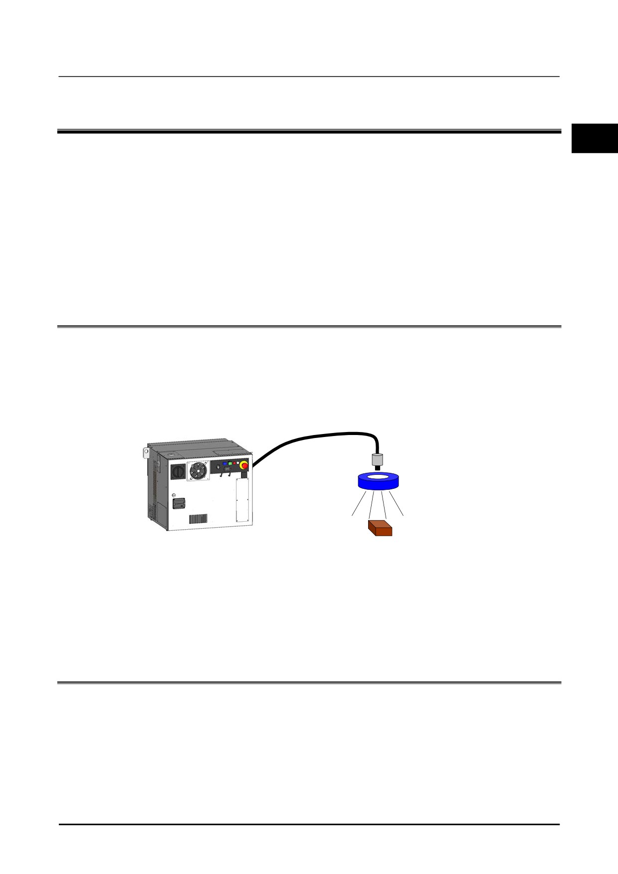
iRVision consists of the following components:
• Camera and lens
• Camera cable
• Lighting Equipment
• Camera multiplexer (used if needed)
Camera Cable
Robot Controller
Camera and Lens
Lighting Equipment
Workpiece
Basic configuration of iRVision
For detailed information about the connection method between the Robot Controller and a camera, please
refer to “R-30iB/ R-30iB Mate CONTROLLER Sensor Mechanical Unit/ Control unit OPERATOR’S
MANUAL B-83434EN”.
The camera and lens of 3D Laser Vision Sensor are sane as the two-dimensional camera, so the 3D Laser
Vision Sensor can also be used for the two-dimensional applications.
2.2
FIXED CAMERA AND ROBOT-MOUNTED CAMERA
Decide where to place the camera according to the workpieces size and location.
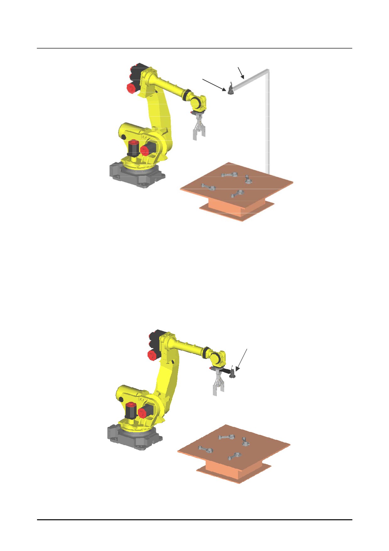
Fixed camera
• Detect workpieces using the camera installed on the stand.
• A fixed camera will always snap the same place from the same distance.
• While the robot transfers the workpieces, iRVision can detect the other workpieces, so the cycle time
can be shortened.
• Use a sufficient strength camera stand so that the camera doesn’t vibrate.
B-83914EN-2/01
5
2. ABOUT VISION SYSTEM
Introduction
Pedestal
Fixed camera
Fixed camera
Robot-mounted camera
• The robot-mounted camera is mounted on the wrist unit of the robot.
• By moving the robot, you can measure different places with a robot-mounted camera.
• When a robot-mounted camera is used, iRVision calculates the position of the workpiece based on
the movement of the robot.
• The camera must be mounted on the final axis of the robot. For example, when a six axis robot is
used, the camera must be mounted on the sixth axis of the robot.
• The camera cable moves according to the robot movement, so be careful so that the cables doesn’t
tangle.
Robot-mounted camera
Robot-mounted camera
6
B-83914EN-2/01
Introduction
2. ABOUT VISION SYSTEM
2.3
SIZE OF A CAMERA’S FIELD OF VIEW
Depending on the size and location of the workpiece, determine the size of the field of view of the
2
camera.
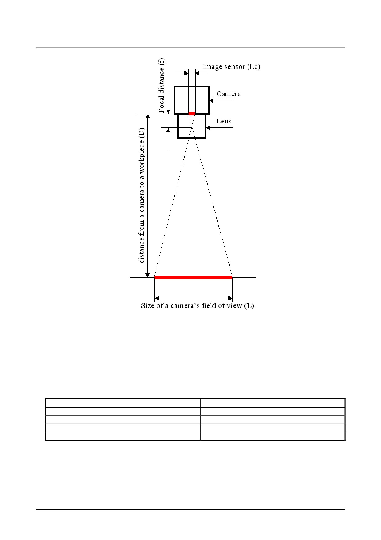
The size of the field of view of the camera is determined by three factors: The size of the image sensor,
the focal distance of the lens, and the distance from the camera to the workpiece.
The size of the image sensor (Lc) is calculated by the following formula.
Lc Cell size Image size (pixels)
The rough value of the field of view of the camera (L) is calculated by the following formula.
L (D f) f Lc
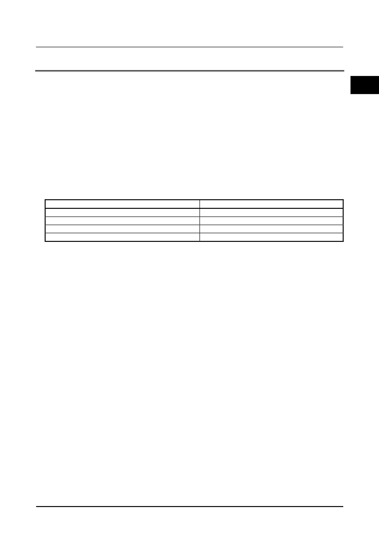
When the distance D from a camera to a workpiece is 700mm and the monochrome camera (SC130EF2)
is used, the view size is shown below table.
Focal distance of the lens
Size of the field of view
8 mm
587 mm 469 mm
12 mm
389 mm 311 mm
16 mm
290 mm 232 mm
25 mm
183 mm 147 mm
The calculation result is an approximate value. Some difference may occur between the calculated value
and the actual measurement value. When an accurate value is required, please confirm by the actual
measurement.
B-83914EN-2/01
7
2. ABOUT VISION SYSTEM
Introduction
Size of a field of view of a camera
If you want to enlarge the view size, there are the following methods.
• Increase the distance from the camera to the workpiece.
• Exchange to a lens with the shorter focal distance.
If the distance from a camera to a workpiece is too near, a lens is not in focus.
The minimum object distance of each lens offered from FANUC is shown in the following table.
The distance from the tip of the workpiece should be longer than the minimum object distance.
Focal distance of the lens
Minimum object distance
8 mm
260 mm
12 mm
260 mm
16 mm
290 mm
25 mm
210 mm
8
B-83914EN-2/01
Introduction
2. ABOUT VISION SYSTEM
2.4
FIXED FRAME OFFSET AND TOOL OFFSET
The fixed frame offset and the tool offset can be used to offset the robot positions. iRVision supports
2
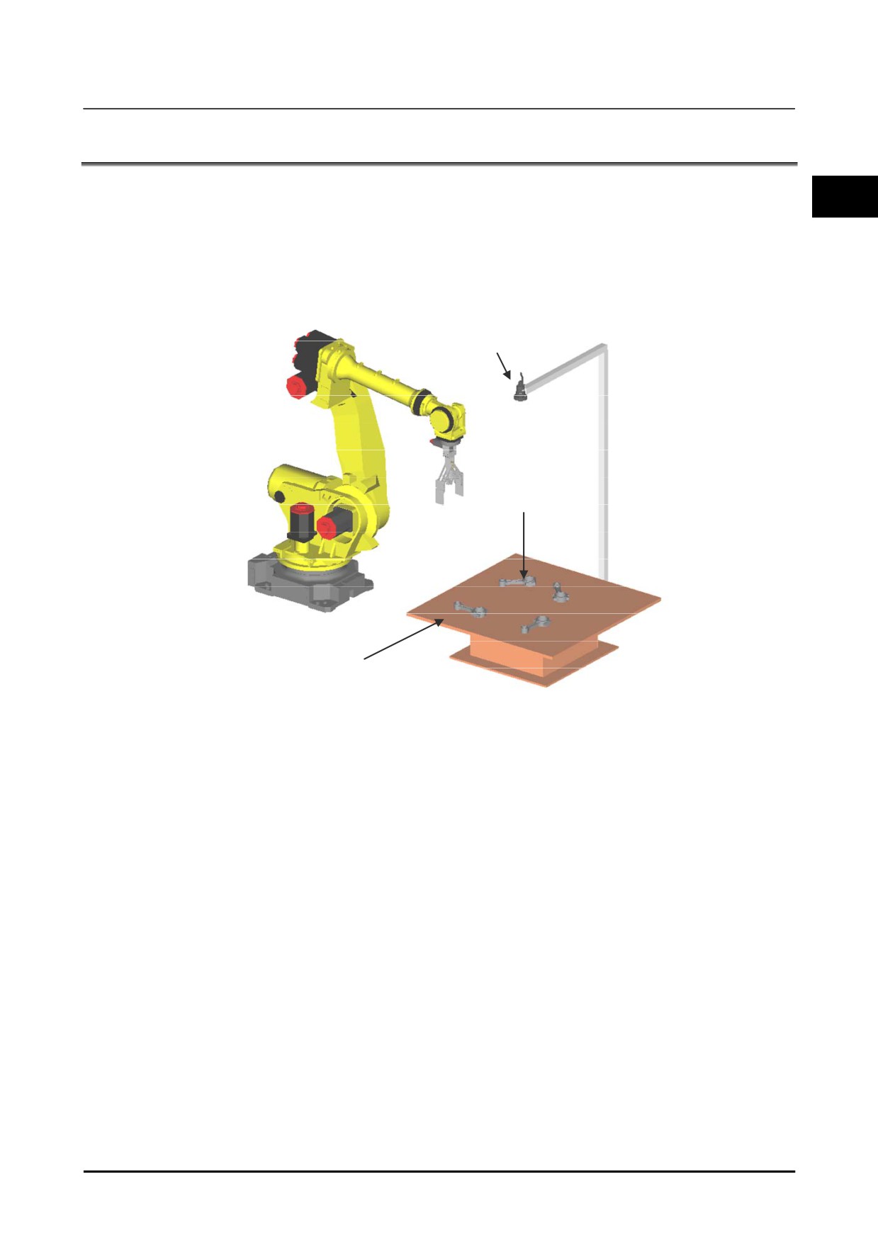
both kinds of robot position offsets.
Fixed frame offset
Detect the workpiece on the table, and offset the robot positions so that the robot works (for example, the
robot picks up the workpiece.) in correct.
Camera
Workpiece
Plane on which a workpiece moves
Fixed frame offset
B-83914EN-2/01
9