FANUC AC SERVO MOTOR ai series, AC SPINDLE MOTOR ai series, SERVO AMPLIFIER ai series. MAINTENANCE MANUAL - page 7

B-65285EN/04
REVISION RECORD
REVISION RECORD
Edition
Date
Contents
04
Aug., 2011
• Addition of an upgrade version of a Servo Amplifier
03
Mar., 2003
• Changing of model names of Servo motor and Spindle motor
• Addition of contents related a(HV)i series
02
Sep., 2002
• Addition of contents related SERVO GUIDE in the Chapter 4 of Part I
• Correction of errors
01
Jul., 2001
r-1
α+ series SERVO AMPLIFIER for 30+-B Start-up and Maintenance manual
1. Type of applied technical documents
Name
α+ series SERVO AMPFLIER for 30+-B Start-up and Maintenance manual
Spec.No./Ver.
B-65285EN/03-02/04
2. Summary of change
Group
Name / Outline
New,Add
Applicable
Correct,Del
Date
Basic Function
It is added that warning level of insulation
Add
Oct. 2012
deterioration detection function can be set by
parameters. Added page : 64
Optional
Function
Unit
Maintenance
Parts
Notice
Correction
Another
03
2012.09.06
Yamada
6,8,10,22,23,26,76 changed S. Hanyuu
α+ series SERVO AMPLIFIER
TITLE
for 30+-B Start-up and
4.1 paragraph is corrected
02
2011.10.12
Yamamoto
M.Takeshita
Maintenance manual
2.2 paragraph is added
04
2012.10.25
Tateda
Page 64 is added
A.Hirai
B-65285EN/03-02/04
NO.
EDT.
DATE
DESIG.
DESCRIPTION
PAGE
1 / 79
INDEX
1. START-UP
3
1.1. COMPONENTS AND ITEMS TO BE CHECKED AT START-UP
3
1.2. INITIALIZING PARAMETERS
13
1.3. TROUBLESHOOTING AT START-UP
22
2. TROUBLESHOOTING
34
2.1. TROUBLESHOOTING PROCEDURES
34
2.2. SMART TROUBLE SHOOTING FUNCTION
35
2.3. ALARM NUMBER
52
3. PERIODIC MAINTENANCE OF SERVO AMPLIFIER
60
3.1. PERIODIC MAINTENANCE ITEM
60
3.2. INSULATION DETERIORATION DETECTION FUNCTION
62
3.3. HOW TO REPLACE THE BATTERY FOR THE ABSOLUTE PULSECORDER
65
4. MAINTENANCE PARTS AND REPLACEMENT METHODS
68
4.1. HOW TO REPLACE FAN MOTORS
68
4.2. HOW TO REPLACE FUSES ON PRINTED-CIRCUIT BOARDS
77
α+ series SERVO AMPLIFIER
TITLE
for 30+-B Start-up and
04
2012.09.25
Tateda
INDEX is corrected
Maintenance manual
02
2011.10.12
INDEX is corrected
B-65285EN/03-02/04
NO.
EDT.
DATE
DESIG.
DESCRIPTION
PAGE
2 / 79
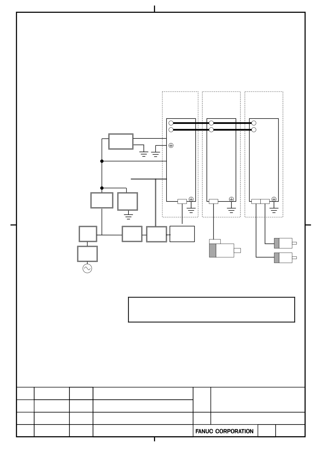
1. START-UP
1.1.
COMPONENTS AND ITEMS TO BE CHECKED AT START-UP
1.1.1
200 V Series Configuration
Power Supply
Spindle Amplifier
Servo Amplifier
αi PS
αi SP
αi SV
DC link
24V Power
24V,0V
Supply
(note 1)
Power Supply
Monitor 3Φ
Coil Power Supply
up to 240VAC
Relay for
magnetic
or 24VDC
contactor
Circuit
Lightning
breaker 2
surge
protector
3φ
Noise
Circuit
Magnetic
AC reactor
filter
breaker 1
contactor
Input
breaker
Spindle motor
Servo motor
200 to 240 VAC
3φ
NOTE
1. Before wiring the power supply monitor, connect a circuit
breaker or fuse so that the wiring can be protected.
α+ series SERVO AMPLIFIER
TITLE
for 30+-B Start-up and
Maintenance manual
B-65285EN/03-02/04
NO.
EDT.
DATE
DESIG.
DESCRIPTION
PAGE
3 / 79
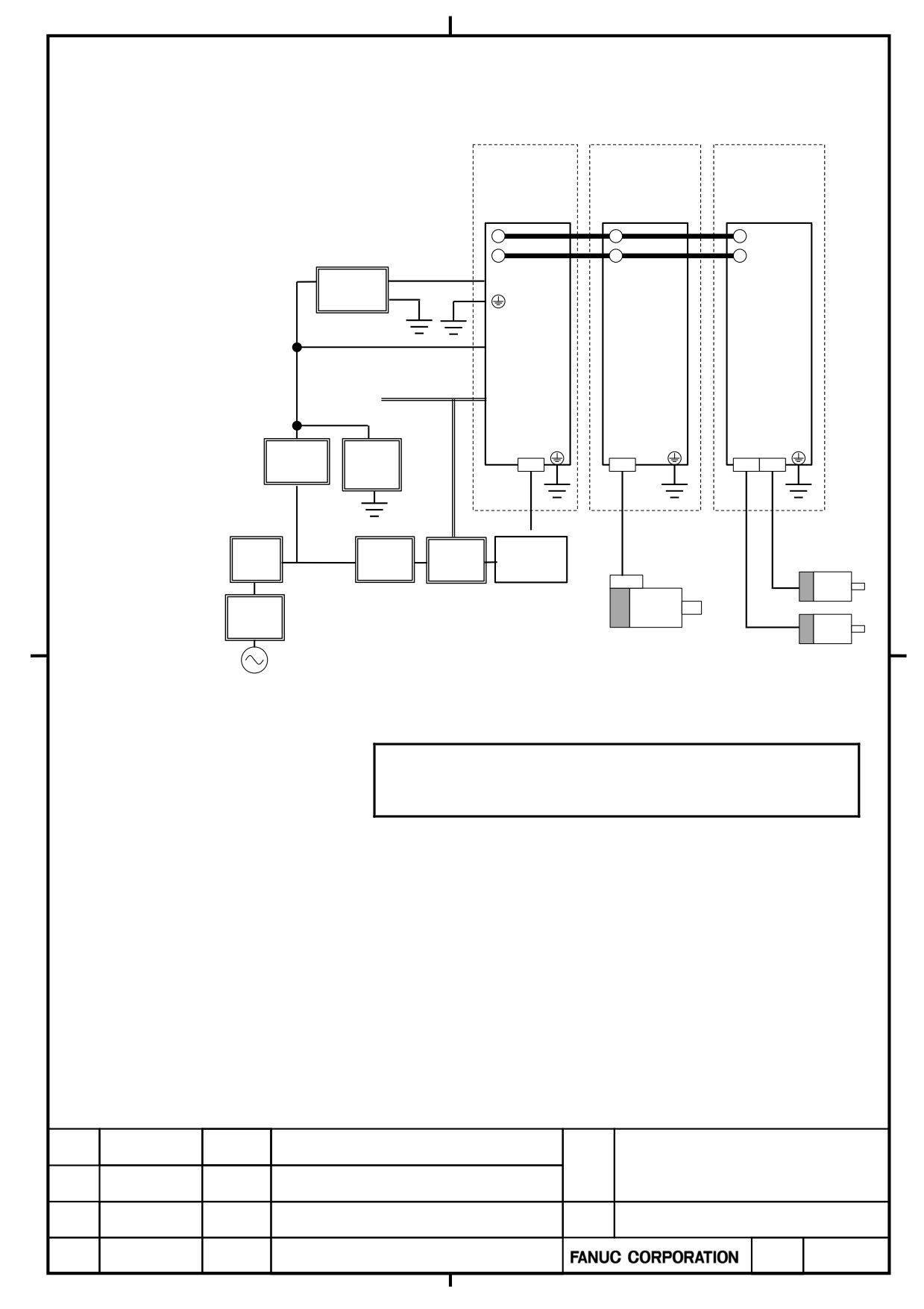
1.1.2
400 V Series Configuration
Power Supply
Spindle Amplifier
Servo Amplifier
αi PS
αi SP
αi SV
DC link
24V Power
24V,0V
Supply
(note 1)
Power Supply
Monitor 3Φ
Coil Power Supply
up to 240VAC
Relay for
magnetic
or 24VDC
contactor
Circuit
Lightning
breaker 2
surge
protector
3φ
Noise
Circuit
Magnetic
AC reactor
filter
breaker 1
contactor
Input
breaker
Spindle motor
Servo motor
400 to 480 VAC
3φ
NOTE
1. Before wiring the power supply monitor, connect a circuit
breaker or fuse so that the wiring can be protected.
α+ series SERVO AMPLIFIER
TITLE
for 30+-B Start-up and
Maintenance manual
B-65285EN/03-02/04
NO.
EDT.
DATE
DESIG.
DESCRIPTION
PAGE
4 / 79
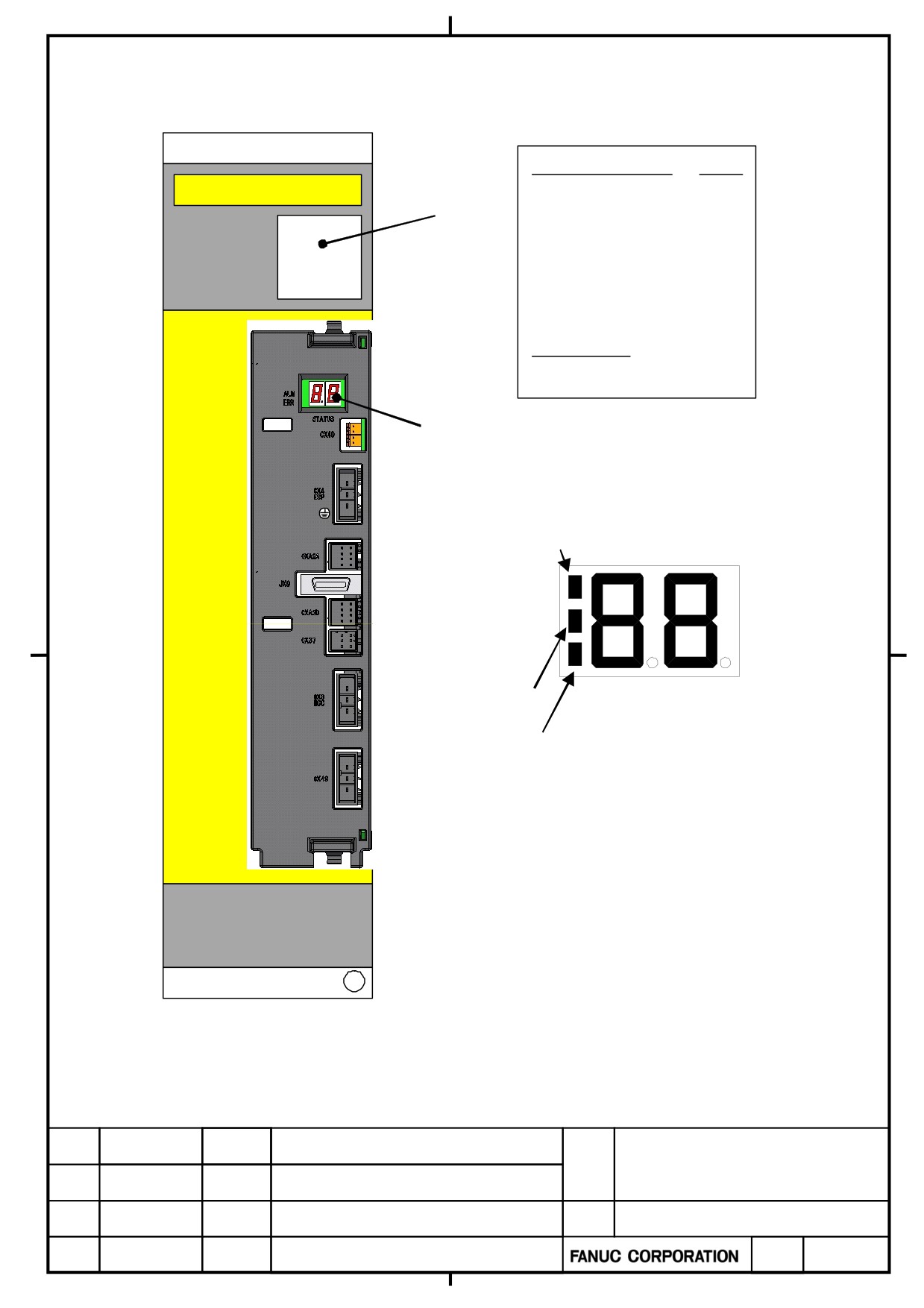
1.1.3
Label and Display on α+ PS
A06B-6200-H011
A
FANUC
Specification
Unit
LABEL
Number
Version
V00000000
Manufacture number
LED display
・Alarm number
・Warning number
・Software series and version
POWER ON LED (GREEN)
NUMBER
ALARM
LED (RED)
ERROR
LED(ORANGE)
POWER ON LED(GREEN):Lighting when control power ON
ALARM LED(RED):Lighting when Alarm status
ERROR LED(ORANGE):Lighting when Error status
α+ series SERVO AMPLIFIER
TITLE
for 30+-B Start-up and
Maintenance manual
B-65285EN/03-02/04
NO.
EDT.
DATE
DESIG.
DESCRIPTION
PAGE
5 / 79
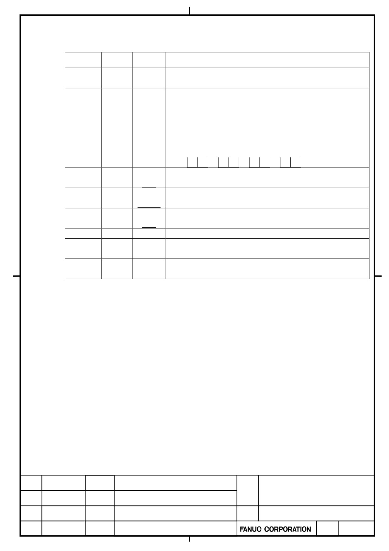
Detail of LED Display of α+ PS
ALARM
ERROR
STATUS
Contents
LED
LED
LED
Control power has not been supplied. Fault of hardware.
LED is off
For detail, refer to “1.3.1 Power supply”
The software series/edition is displayed at 4 sessions for about 4
seconds after the power is turned on.
First 1 sec: Upper 2 digits of the software series
Number /
Second 1 sec: Lower 2 digits of the software series
alphabet
Third 1sec : Upper 2 digits of software version
Forth 1sec : Lower 2 digits of software version
Example) In case of Software serie/version 9G00/01.0
9
G
→
0
0
→
0
1
→
_
0
--
Serial communication with the servo or spindle amplifier is being
Blink
established
--
Serial communication with the servo or spindle amplifier is
Lighting
established
00
Start up main power (Precharging)
Blink
00
Ready main power
Number
Lighting
Alarm status
01~
Number
Warning status
01~
α+ series SERVO AMPLIFIER
TITLE
for 30+-B Start-up and
Maintenance manual
03
2012.09.06
Yamada
Added to contents of “LED is off”
B-65285EN/03-02/04
NO.
EDT.
DATE
DESIG.
DESCRIPTION
PAGE
6 / 79
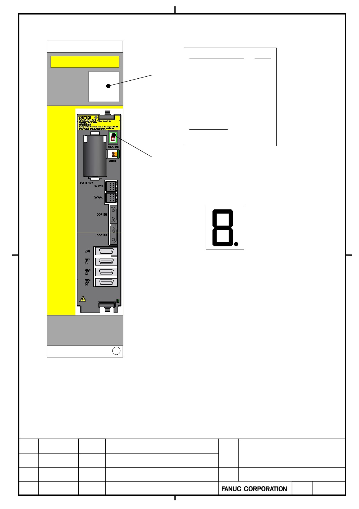
1.1.4
Label and Display on α+ SV
A06B-6240-H210
A
FANUC
Specification
Unit
LABEL
Number
Vertion
V00000000
Manufacture Number
LED display
・Alarm number
・Warning number
・Software series and version
Number
α+ series SERVO AMPLIFIER
TITLE
for 30+-B Start-up and
Maintenance manual
B-65285EN/03-02/04
NO.
EDT.
DATE
DESIG.
DESCRIPTION
PAGE
7 / 79
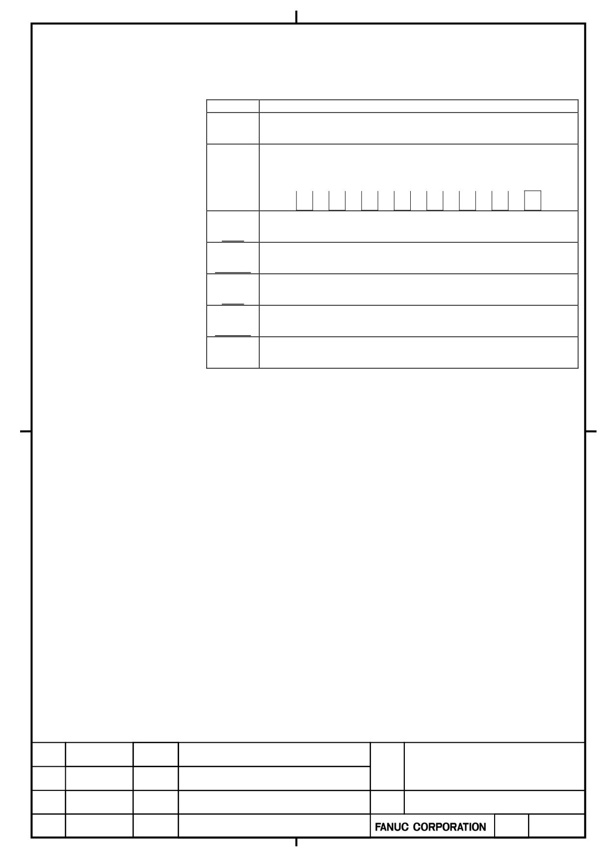
Detail of LED Display of α+ SV
LED
Contents
Control power has not been supplied. Fault of hardware
LED is off
For detail, refer to “1.3.2 Servo amplifier”
The software series/version is displayed at 4seconds after the
Number
power is turned on.
Lighting
Example) In case of software series/version is 9H00/01.0
9
→
H
→
0
→
0
→
0
→
1
→
→
0
-
Self-Check
Blink
-
SV is waiting for a ready signal
Lighting
-
Measuring isolation resistor
Blink
-
SV is ready to operate
Lighting
Number
Alarm state
1~
α+ series SERVO AMPLIFIER
TITLE
for 30+-B Start-up and
Maintenance manual
03
2012.09.06
Yamada
Added to contents of “LED is off”
B-65285EN/03-02/04
NO.
EDT.
DATE
DESIG.
DESCRIPTION
PAGE
8 / 79
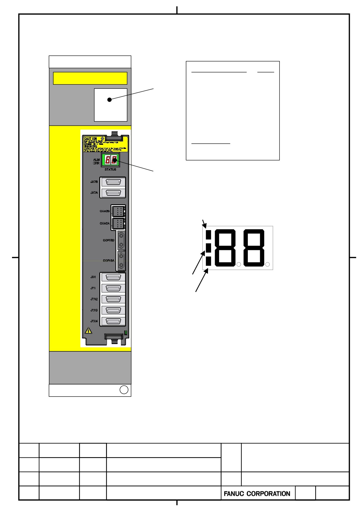
1.1.5
Label and Display on α+ SP
A06B-6220-H011
A
FANUC
Specification
Unit
LABEL
Number
Version
V00000000
Manufacture number
LED display
・Alarm number
・Warning number
・Software series and version
POWER ON LED (GREEN)
NUMBER
ALARM
LED (RED)
ERROR
LED(ORANGE)
POWER ON LED(GREEN):Lighting when control power ON
ALARM LED(RED):Lighting when Alarm status
ERROR LED(ORANGE):Lighting when Error status
α+ series SERVO AMPLIFIER
TITLE
for 30+-B Start-up and
Maintenance manual
B-65285EN/03-02/04
NO.
EDT.
DATE
DESIG.
DESCRIPTION
PAGE
9 / 79
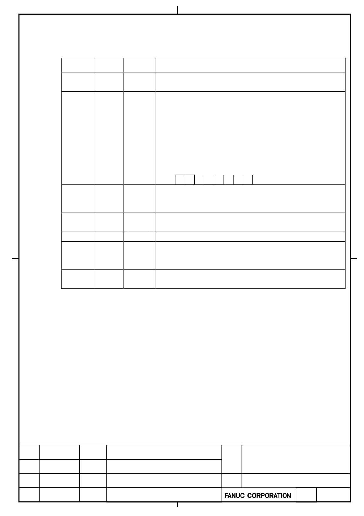
Detail of LED Display of α+ SP
ALARM
ERROR
STATUS
Contents
LED
LED
LED
Control power has not been supplied. Fault of hardware.
LED is off
For detail, refer to “1.3.3 Spindle amplifier”
For about 3.0 s after the control power supply is switched on, the
spindle software series No. and the spindle software edition No. are
indicated.
First 1 sec
:
A
Number /
Second 1 sec : The lower two digits of the spindle software series
alphabet
No.
Third 1sec
: The spindle software edition No.
Example) A0: Software series No. 9DA0
04: Software edition D
A
→
A
0
→
0
4
The CNC has not been switched on.
--
The machine is waiting for serial communication and parameter
Blink
loading to end.
--
Parameter loading has ended.
Lighting
The motor is not supplied with power.
00
The motor is supplied with power.
Alarm status
Number
Lighting
The SPM is not operable.
01~
See Chapter 1 of Part II.
Number
Warning status
Lighting
01~
Incorrect parameter setting or improper sequence.
α+ series SERVO AMPLIFIER
TITLE
for 30+-B Start-up and
Maintenance manual
B-65285EN/03-02/04
NO.
03
2012.09.06
Yamada
Added to contents of “LED is off”
EDT.
DATE
DESIG.
DESCRIPTION
PAGE
10 / 79
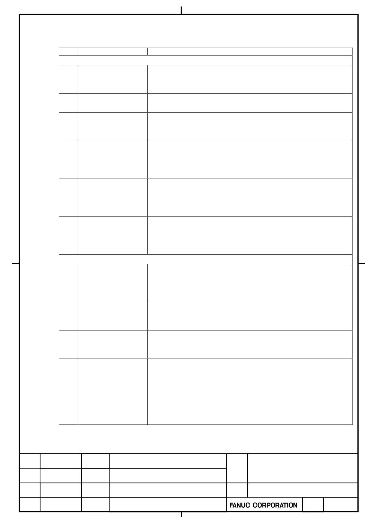
1.1.6
Check Items
No.
Description
Check method
Servo amplifier installation status check
1
Servo amplifier and
Check the combination of the servo amplifier and servo motor referring to
servo motor
Section 4.1 of “Į+ series Servo Amplifier Descriptions” (B-65282EN/06).
specifications
2
Flange packing
Check the supplied packing is attached properly and that there is no gap
between the control panel and amplifier flange.
3
Maintenance area
Please keep a maintenance area for the amplifier.
For details, refer to Section 5.1 of the document (B-65282EN/06-18) attached
to “Į+ series Servo Amplifier Descriptions”.
4
Preventing contact with
Check a protective plate is attached to the DC link terminal board properly and
any current-carrying
the terminal board cover is locked.
section
For details, refer to Section 5.3 of the document (B-65282EN/06-18) attached
to “Į+ series Servo Amplifier Descriptions”.
5
Order of amplifier
As for the α+SP45HV or the larger model, there is a rule to place the
locations
amplifiers.
For details, refer to Section 5.3 of the document (B-65282EN/06-18) attached
to “Į+ series Servo Amplifier Descriptions”.
6
Prevent cutting fluid
Take a measure to prevent electroconductive, flammable, and corrosive
intrusion
material as well as mist and water drop from getting in the unit. For the detail
of an effective closeness of the control panel, refer to Appendix G of “Į+
series Servo Amplifier Descriptions” (B-65282EN/06).
Servo amplifier wiring status check
7
Tightening terminal
When connecting wires to the servo amplifier terminal board, be sure to
board screws
tighten the screws with a proper torque. For the detail of the tightening torque
for the terminal board screws, refer to Subsection 5.5.2.9 of “Į+ series Servo
Amplifier Descriptions” (B-65282EN/06).
8
Connecting a protective
Use a proper cable for grounding in order to prevent electrical shocks at a
ground
ground fault. For details, refer to Subsection 9.3.1.7 of “Į+ series Servo
Amplifier Descriptions” (B-65282EN/06).
9
Installing a lightning
In order to prevent damage due to a surge voltage applied to the input power
surge protector
supply, install a lightning surge protector. For details, refer to Appendix A of
“Į+ series Servo Amplifier Descriptions” (B-65282EN/06).
10
Measure for noise
Check that ground wires, including feedback cable shielding clamps, are
connected to proper places to maintain a stable operation of the machine. For
details, refer to Section 5.2 of “Į+ series Servo Amplifier Descriptions”
(B-65282EN/06) and Subsection 7.2.5 of the document (B-65282EN/06-18)
attached to “Į+ series Servo Amplifier Descriptions”. Also refer to Subsection
7.2.8 if the 24 V power supply is shared between the servo amplifier and the
CNC.
(Continued on the next page)
α+ series SERVO AMPLIFIER
TITLE
for 30+-B Start-up and
Maintenance manual
B-65285EN/03-02/04
NO.
EDT.
DATE
DESIG.
DESCRIPTION
PAGE
11 / 79
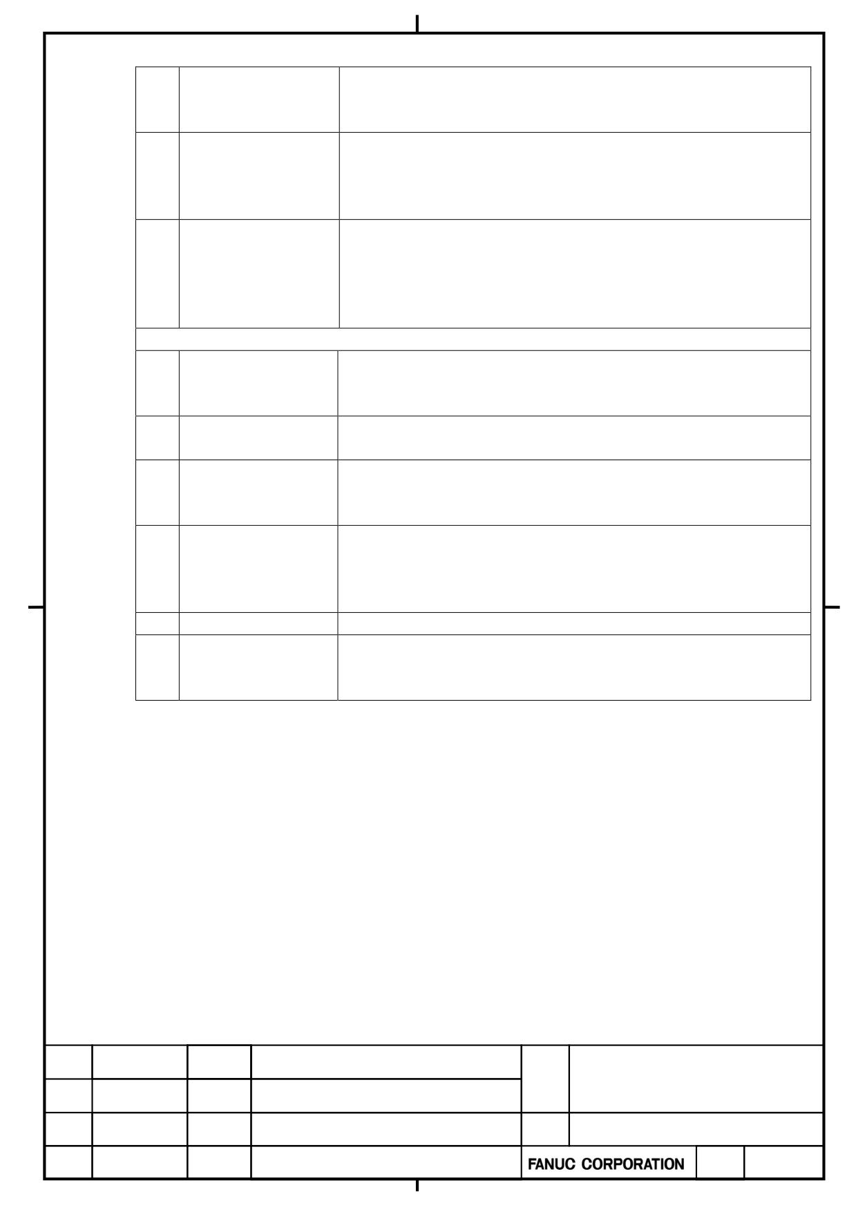
(Continued from the previous page)
11
Order of motor power
If the order of motor power line phases is incorrect, there is a risk of an
line phases
unexpected behavior of motor. So, make sure that the power wires are
connected to the motor properly.
12
Checking the axis where
If the axis where motor feedback and power wires are connected is incorrect,
motor feedback and
there is a risk of an unexpected behavior of motor. So, make sure that the
power wires are
connection is correct.
connected
13
Battery connection
Do not connect the built-in batteries in parallel. Please make sure, if the
built-in batteries are used with an amp-to-amp battery connection cable
(CXA2A/B or BATL (B3)) attached, they may be connected in parallel. For
details, refer to Subsection 9.3.2.10 of “Į+ series Servo Amplifier
Descriptions” (B-65282EN/06).
Operation start-up check
14
Power supply voltage
Before turning power on, check that the power supply voltage is in its proper
check
range. For details of the power supply voltage specification, refer to Section
2.1 of “Į+ series Servo Amplifier Descriptions” (B-65282EN/06).
15
Ground potential check
The 400 V servo amplifier supports only neutral grounding. For details, refer
to Section 2.1 of “Į+ series Servo Amplifier Descriptions” (B-65282EN/06).
16
Ground fault interrupter
Use a ground fault interrupter that supports inverters. For explanations about
setting
leakage current, refer to Section 5.1 of “Į+ series Servo Amplifier
Descriptions” (B-65282EN/06).
17
Control power check
Check that the voltage of the 24 V power supply for amplifiers is in its proper
range and the selected current capacity is proper. For details, refer to Section
4.5 and Subsection 7.2.8 of the document (B-65282EN/06-18) attached to “Į+
series Servo Amplifier Descriptions”.
18
Parameter setting
Set initial parameters while referencing Section 1.2 of this document.
19
Handling early failures
Solve start-up problems, such as being impossible to turn power on, motor
failing to rotate, and alarm occurrence, while referencing Section 1.3 of this
document.
α+ series SERVO AMPLIFIER
TITLE
for 30+-B Start-up and
Maintenance manual
B-65285EN/03-02/04
NO.
EDT.
DATE
DESIG.
DESCRIPTION
PAGE
12 / 79
1.2.
INITIALIZING PARAMETERS
1.2.1
Common Power Supply
The common power supply (PS) for the 30+-B series is controlled by software. So, information concerning the
power supply can be known on the CNC. Using these informations makes it possible to diagnose failures resulting
from power supply fluctuation.
Unlike the servo amplifier (SV) or spindle amplifier (SP), PS cannot communicate directly with CNC. So, the
power supply information is transferred through SV or SP to CNC.
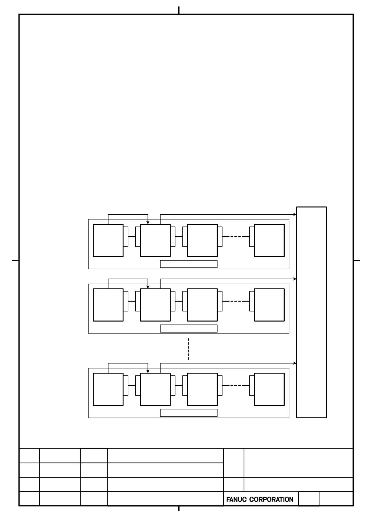
1.2.1.1 Amplifier group number
A group of one PS and the servo and spindle amplifiers connected to the PS is defined as an “amplifier group”.
This means that a system having more than one PS has more than one amplifier group. A unique number is
assigned to each amplifier group. The unique number is described as “amplifier group number”.
1.2.1.2 PS control axis
The PS is connected to amplifiers via the CXA2x connector. In this connection, let us refer to an axis driven by
the servo/spindle amplifier nearest to the PS is described as “PS control axis”.
The power supply information mentioned above is transferred through this PS control axis to the CNC.
power supply information
power supply information
C
C
C
C
C
C
X
X
X
X
X
X
PS
SV or SP
SV or SP
SV or SP
A
A
A
A
A
A
2
2
2
2
2
2
A
B
A
B
A
B
PS control
axis
amplifier group "1"
power supply information
power supply information
C
C
C
C
C
C
X
X
X
X
X
X
PS
A
A
SV or SP
A
A
SV or SP
A
A
SV or SP
2
2
2
2
2
2
C
A
B
A
B
A
B
PS control
N
axis
C
amplifier group "2"
power supply information
power supply information
C
C
C
C
C
C
X
X
X
X
X
X
PS
SV or SP
SV or SP
SV or SP
A
A
A
A
A
A
2
2
2
2
2
2
A
B
A
B
A
B
PS control
axis
amplifier group "N"
α+ series SERVO AMPLIFIER
TITLE
for 30+-B Start-up and
Maintenance manual
B-65285EN/03-02/04
NO.
EDT.
DATE
DESIG.
DESCRIPTION
PAGE
13 / 79
1.2.1.3 Parameter setting for specifying a PS control axis
Using the servo and spindle amplifiers for the 30+-B series requires the following procedure.
1.2.1.3a Parameter setting procedure
In order for the CNC software to recognize the PS control axis, it is necessary to set an amplifier group number
in either of the following parameters:
Parameter No. 2557 in case the PS control axis is a servo axis
Parameter No. 4657 in case the PS control axis is a spindle axis
This setting can be made automatically with the following procedure.
(1) Set bit 0 (APS) of parameter No. 11549 to 1.
The message “PW0000 POWER MUST BE OFF” appears on the alarm message screen. So turn the CNC
power off and on again. Parameters Nos. 2557 and 4657 are automatically set with an amplifier group number,
thus completing PS control axis parameter setting.
* Upon completion of automatic parameter setting, bit 0 of parameter No. 11549 returns to 0.
* If the amplifier configuration is changed, the alarm “PS CONTROL AXIS ERROR” occurs just after CNC
start-up. So, perform automatic parameter setting again.
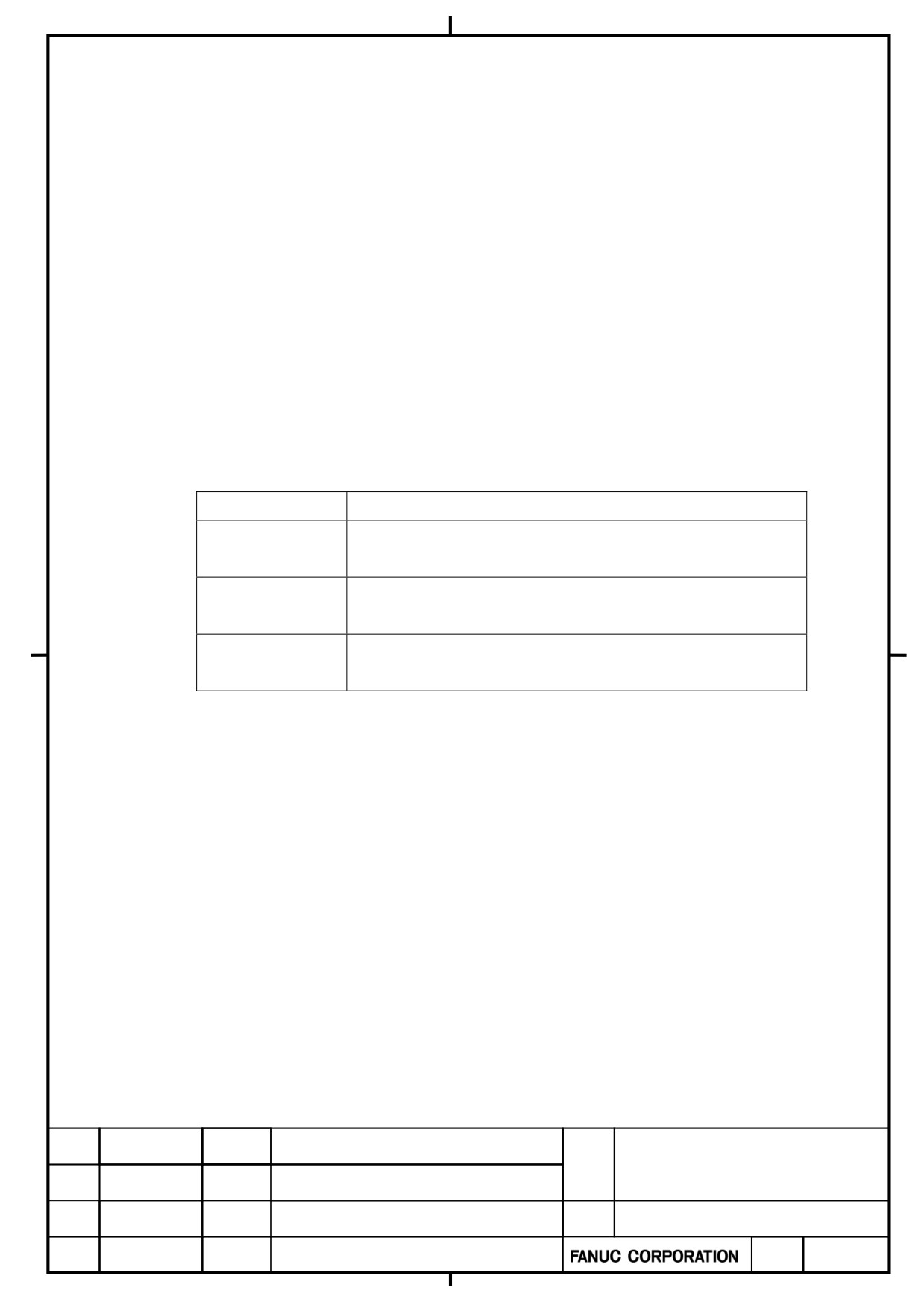
Related parameter
Description
No.11549#0(APS)
Setting this parameter to 1 causes an amplifier group number to be
automatically set in PS control axis parameter No. 2557 or 4657.
No.2557
In case the servo axis is a PS control axis, an amplifier group number
is set for the PS control axis.
No.4657
In case the spindle axis is a PS control axis, an amplifier group
number is set for the PS control axis.
α+ series SERVO AMPLIFIER
TITLE
for 30+-B Start-up and
Maintenance manual
B-65285EN/03-02/04
NO.
EDT.
DATE
DESIG.
DESCRIPTION
PAGE
14 / 79
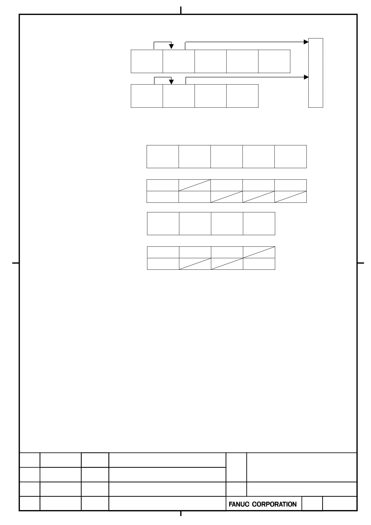
1.2.1.3b Concrete parameter setting examples
Amplifier Group1
PS
SP
SV
SV
SV
C
S1
X
Y
Z
N
C
Amplifier Group2
PS
SV
SV
SP
A
B
S2
For the amplifier configuration shown above, the parameters are set as shown below. Amplifier group numbers 1
and 2 are assigned automatically.
Amplifier Group1
PS
SP
SV
SV
SV
S1
X
Y
Z
No.2557
0
0
0
No.4657
1
Amplifier Group2
PS
SV
SV
SP
A
B
S2
No.2557
2
0
No.4657
0
α+ series SERVO AMPLIFIER
TITLE
for 30+-B Start-up and
Maintenance manual
B-65285EN/03-02/04
NO.
EDT.
DATE
DESIG.
DESCRIPTION
PAGE
15 / 79
1.2.2
Servo Amplifiers
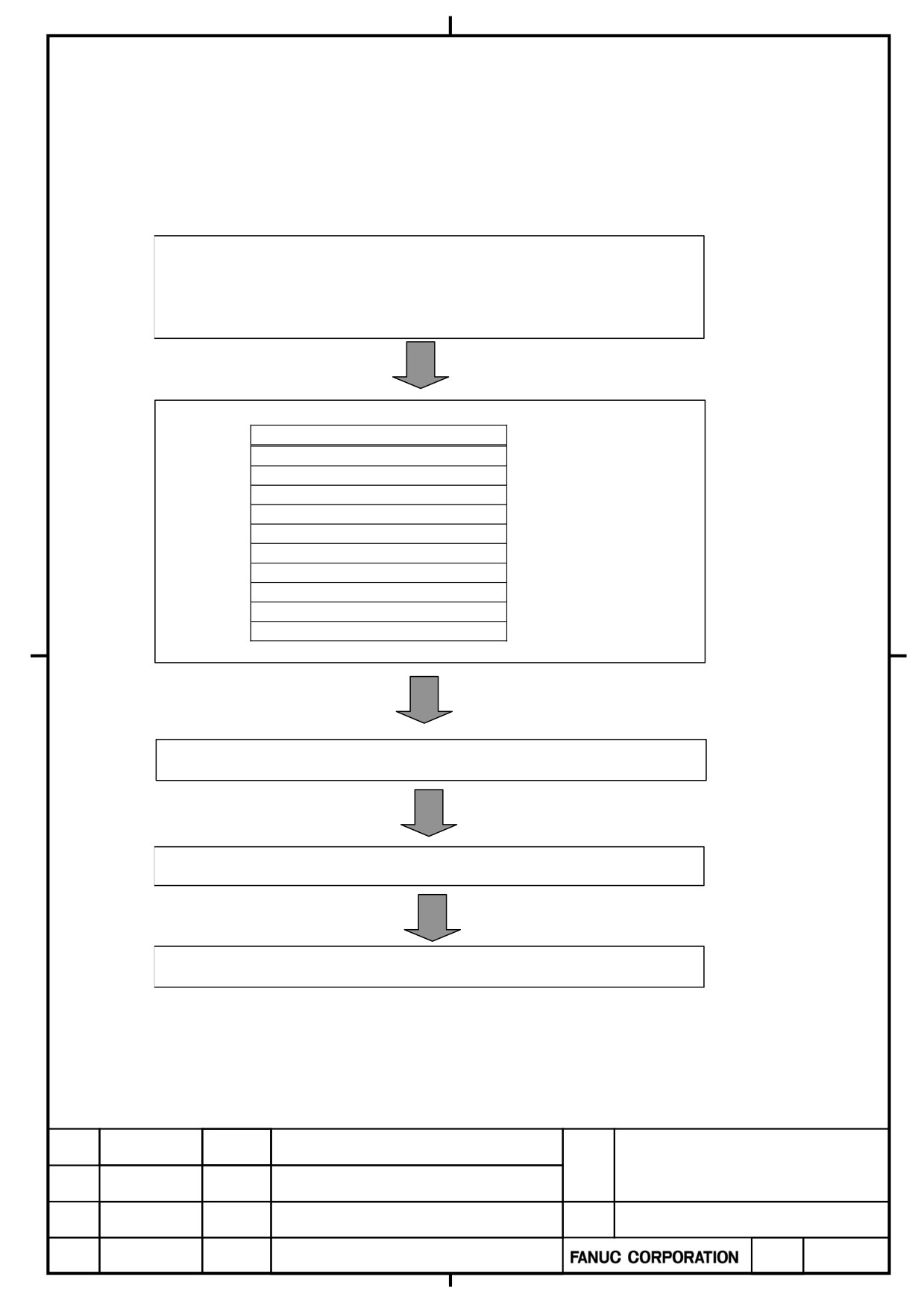
1.2.2.1 Servo parameter initialization procedure
The initialization procedure for servo amplifiers and servo motors is described below. For details of each item of
the procedure, refer to “FANUC AC SERVO MOTOR α+ series/FANUC AC SERVO MOTOR β+ series/FANUC
LINEAR L+S series/FANUC BUILT-IN SERVO MOTOR D+S series Parameter Manual” (B-65270).
Preparation
- In emergency stop state, switch on CNC
- Set parameter write enable
- Servo adjusting screen
Setting of servo parameter
Setting
Initialization bits
Motor No.
AMR
CMR
Flexible feed gear
Move direction
Velocity pulse
Reference counter
Full closed loop
Servo loop gain
Turn power off then on
Absolute position detection setting
End of parameter setting
α+ series SERVO AMPLIFIER
TITLE
for 30+-B Start-up and
Maintenance manual
B-65285EN/03-02/04
NO.
EDT.
DATE
DESIG.
DESCRIPTION
PAGE
16 / 79
1.2.2.2 Multi-axis amplifier start-up
The conventional multi-axis amplifier cannot become ready unless the start-up conditions for all axes are satisfied.
However, the multi-axis servo amplifier for the 30i-B series can become ready for individual axes separately if the
start-up conditions for them are satisfied.
Multi-axis amplifier ready status indicator
The 7-segment LED indicator on the multi-axis servo amplifier for the 30i-B series can indicates “0.” (dotted zero)
meaning a ready status for some axes and a not-ready status for others as well as “0” meaning a ready status for all
axes and “-” meaning a not-ready status for all axes.
7-segment LED
Amplifier status
Description
indicator
Not ready for all axes (same as conventional)
-
Not ready (for all axes)
All axes are braked dynamically and inoperable.
Ready for all axes (same as conventional)
0
Ready (for all axes)
All axes are operable.
Ready for some axes and not ready for others.
This indication differs from the all-axis ready status
indication in that the dot lights.
Ready (except for some
0.
Only the axes for which the amplifier is ready are
axes)
operable.
The axes for which the amplifier is not ready are braked
dynamically.
・Multi-axis amplifier behavior at alarm occurrence
If the former multi-axis servo amplifier detects an alarm even on one axis, it becomes Not ready for all axes
regardless of what the alarm is like and applies a dynamic brake to all the axes to bring them to halt. If the
multi-axis servo amplifier for the 30i-B series detects an individual-axis alarm (such as an IPM alarm) on any axis,
however, it becomes Not ready only for that axis and stays ready for the other axes in the servo amplifier.
・No restriction on the multi-axis amplifier at alarm occurrence
Even if an alarm occurs on the brake control function, quick stop function, or the Gravity-axis drop prevention
function at an emergency stop for any axis, unlike the former multi-axis servo amplifier, there is no restriction on
the multi-axis servo amplifier for the 30i-B series regarding any application using the operation of the other axes.
α+ series SERVO AMPLIFIER
TITLE
for 30+-B Start-up and
Maintenance manual
B-65285EN/03-02/04
NO.
EDT.
DATE
DESIG.
DESCRIPTION
PAGE
17 / 79
[Behavior of axes (normal axes) at alarm occurrence on any other axis]
Behavior of normal axes
Alarm
Servo amplifier for
Conventional servo amplifier
the 30i-B series
<1>
Alarm (such as excessive-error alarm)
Possible to delay the ready status
Possible to delay the
detected by the servo or CNC software
of the servo amplifier.*
ready status of the
servo amplifier.*
<2>
Individual-axis alarm detected by the servo
Possible to delay the ready status
Possible to delay the
amplifier
of the servo amplifier only for the
ready status of the
<1> Abnormal Motor current
one-axis amplifier.*
servo amplifier for all
<2> IPM alarm
(Impossible to delay the ready
amplifiers.*
<3> DB relay abnormal alarm
status of the servo amplifier if a
multi-axis amplifier detects an
alarm for axes of the same
amplifier.)
<3>
Alarms other than <1> or <2> above
Becomes Not ready instantly.
Becomes Not ready
instantly.
*It is possible to pull up normal vertical axes while the ready status of the servo amplifier is being delayed.
α+ series SERVO AMPLIFIER
TITLE
for 30+-B Start-up and
Maintenance manual
B-65285EN/03-02/04
NO.
EDT.
DATE
DESIG.
DESCRIPTION
PAGE
18 / 79
・Supporting the axis detach function for multi-axis amplifiers
Conventionally, the axis detach function has been applicable only to axes driven by a one-axis servo amplifier. Now,
the detach function is applicable to each axis driven by the multi-axis servo amplifier for the 30i-B series.
・Setting dummy axes for multi-axis amplifiers
Starting up a specific axis on the conventional multi-axis amplifier requires attaching a dummy connector to the
axes not in use. With the servo amplifier for the 30i-B series, it is possible to start up only arbitrary axes. So, it is
unnecessary to attach a dummy connector to any axis not in use.
・Sharing a multi-axis amplifier with two or more paths
If the conventional multi-axis amplifier is shared among multiple paths, it is necessary to input a signal for
ignoring the VRDY-OFF alarm when the amplifier becomes Not ready for an axis being used by one path, so that
it will not become Not ready for axes in use by the other paths. For the servo amplifier for the 30i-B series, it is
unnecessary to input such a signal.
CAUTION
1. Note on synchronization control and tandem control
If an alarm occurs on one of the axes used on a multi-axis amplifier under synchronization or tandem
control, it is necessary for the multi-axis amplifier to become Not ready immediately also for the other
axes in order to prevent machine distortion. To meet this requirement, be sure to enable the servo
software’s “servo alarm 2-axis simultaneous monitoring function” for axes under synchronization or
tandem control.
In some cases, implementing synchronization or tandem control for two axes driven by the
conventional multi-axis amplifier caused the amplifier to be become Not ready for the two axes
simultaneously at alarm occurrence as if the “servo alarm 2-axis simultaneous monitoring function” had
operated.
Because the ready status conditions of the multi-axis amplifier for the 30i-B series for each axis are
independent of one another, using the multi-axis amplifier does not work in place of the “servo alarm
2-axis simultaneous monitoring function”. For this reason, be sure to enable the “servo alarm 2-axis
simultaneous monitoring function” for axes under synchronization or tandem control also when the
multi-axis amplifier is used. Refer to “Parameter Manual” for detailed descriptions of the “servo alarm
2-axis simultaneous monitoring function” and the related parameter setting.
2. If an alarm (such as a DC link low-voltage alarm) common to all axes occurs, any axis driven by the
multi-axis amplifier can be the cause of the alarm in the same manner as with the conventional
amplifier, resulting in the amplifier becoming Not ready simultaneously for all axes and a dynamic
brake being applied to all axes to bring them to halt.
3. If an emergency stop signal (input signal to the connector CX4 of the PS) is input, the amplifier
becomes Not ready for all axes and applies a dynamic brake to all axes to bring them to halt.
α+ series SERVO AMPLIFIER
TITLE
for 30+-B Start-up and
Maintenance manual
B-65285EN/03-02/04
NO.
EDT.
DATE
DESIG.
DESCRIPTION
PAGE
19 / 79
1.2.3
SPINDLE AMPLIFIER
1.2.3.1 PARAMETER FOR SPINDLE SERIAL OUTPUT
Only the list of parameters for SPINDLE SERIAL OUTPUT is mentioned.
As for the detal of these parameter, refer to 11.2 “SPINDLE SERIAL OUTPUT” of FANUC Series 30+ / 31+ /
32+ -MODEL B CONNECTION MANUAL (FUNCTION)
Parameter
Description
number
30i-B
(Analog/Serial)Selection of Spindle
3716#0
(Set to “1”)
The multi-spindle control function
3702#1
(The multi-spindle control function is used
/not used)
3717
The spindle amplifier number of each spindle
3718
Subscript for display of spindle (main spindle)
3719
Subscript for display of spindle (sub-spindle)
Note
When a serial spindle is used, the option for spindle serial
output is required.
About FSSB Setting,
refer to 1.4.4「FSSB Setting」of FANUC Series 30+ / 31+ / 32+ -MODEL B CONNECTION MANUAL
(FUNCTION).
1.2.3.2 Automatic Spindle Parameter Initialization
An automatic setup of spindle parameters (No.4000-No.4799) is described as follow.
Note
When you do not want to initialize the adjusted parameters,
don’t perform automatic spindle parameter initialization.
1.2.3.2a Parameter List
Parameter No.
Description
30i-B
4019#7
Function for automatically initializing spindle
parameters.
4133
Spindle motor model code
α+ series SERVO AMPLIFIER
TITLE
for 30+-B Start-up and
Maintenance manual
B-65285EN/03-02/04
NO.
EDT.
DATE
DESIG.
DESCRIPTION
PAGE
20 / 79
1.2.3.2b Procedure for automatic spindle parameter initialization
Perform automatic spindle parameter initialization by following the procedure below.
<1> Set the model code for the desired motor for automatic parameter initialization.
Parameter No.
Description
30i-B
4133
Model code
Note
1 The control method usable with the α+ series spindle is
spindleHRV control only. The conventional control method is
not supported.
2 About the model code of each motor,
refer to FANUC AC SPINDLE MOTOR α+ series PARAMETER
MANUAL B-65280JA.
3 When using a spindle motor that has no model code, set model
code “300” (“400” for a spindle motor with speed range
switching control) for automatic parameter setting, then
manually input data according to the parameter table for each
motor model.
<2> Set the relevant parameter to enable automatic spindle parameter initialization.
Parameter No.
Description
30i-B
4019#7
1
Note
This bit is reset to its original value after automatic parameter
initialization.
<3> Turn the CNC off, then on again. Then, the spindle parameters specified with a model code are automatically
initialized.
α+ series SERVO AMPLIFIER
TITLE
for 30+-B Start-up and
Maintenance manual
B-65285EN/03-02/04
NO.
EDT.
DATE
DESIG.
DESCRIPTION
PAGE
21 / 79
1.3.
Troubleshooting at Start-up
1.3.1
Power supply
(1) The LED on power supply is off
When the LED on power supply does not become on after the main circuit breaker is turned on.
No.
Cause of trouble
Check method
Action
The 24V control power is
Check the voltage of the external
Check whether the external
1
not supplied.
power supply (24V).
power supply is faulty.
Check whether the cable attached to
Check the cable attached to
2
The cable is defective.
the connector CXA2A/B is
the connector CXA2A/B.
disconnected or short-circuited.
The power is externally
Check whether the cable for 24V
3
connected to 0 V, GND,
Replace or repair the cable.
power is short-circuited
or the like.
If the fuse blows, the printed
circuit board may be faulty.
Check whether the fuse on the
Replace the unit.
printed circuit board for the control
has blown.
Note)
See Chapter 4.2 about the location
Reverse connection of 0V
of the fuse.
There is a blown fuse on
and 24V of the
4
the printed circuit board.
connector(CXA2D) for the
The fuse blow can be confirmed by
external DC24V make the
checking the element of the fuse
fuse blow.
visually or removing the fuse and
[Countermeasure]
checking the connection of the
1.Replace the fuse.
element of the fuse by the tester.
2.Change to the correct
connection.
If the cause is not No.1 - 4, the
The printed circuit board
5
printed circuit board of servo
Replace the unit.
is defective.
amplifier may be faulty.
α+ series SERVO AMPLIFIER
TITLE
for 30+-B Start-up and
Maintenance manual
03
2012.09.06
Yamada
Added to contents of NO.4 in table
B-65285EN/03-02/04
NO.
EDT.
DATE
DESIG.
DESCRIPTION
PAGE
22 / 79
1.3.2
Servo amplifier
(1)The LED on servo amplifier is off
When the LED on servo amplifier does not become on after the main circuit breaker is turned on.
No.
Cause of trouble
Check method
Action
The
24V control power
Check the voltage of the 24V power
1
Check the 24V power supply
supply is not supplied
supply
Checke that the cable connected
Checke the cable connected
the CXA2A/2B is disconnented or
the CXA2A/2B
2
The cable is defective
short
Check whether 5V power supply
Checke the feedback cable
short-circuits by the feedback cable.
The power supply is
Please check whether the power
Exchange or repair the cable.
3
short-circuited externally.
cable is short-circuited.
Since Control PCB may be
out of order when this fuse is
blown, please exchange the
Check the fuse on the control PCB
unit.
(Reffer to 4.2 about position of
Note)
fuse)
Reverse connection of 0V
and 24V of the
Blown fuse in the control
4
The fuse blow can be confirmed by
connector(CXA2A/B) for the
circuit
checking the element of the fuse
communication between
visually or removing the fuse and
amplifiers make the fuse
checking the connection of the
blow.
element of the fuse by the tester.
[Countermeasure]
1.Replace the fuse.
2.Change to the correct
connection.
If it does not correspond to No.1~4,
The PCB of servo
5
the PCB of servo amplifier may be
Exchange the servo amplifier
amplifier is defective
defective.
α+ series SERVO AMPLIFIER
TITLE
for 30+-B Start-up and
Maintenance manual
B-65285EN/03-02/04
NO.
03
2012.09.06
Yamada
Added to contents of NO.4 in table
EDT.
DATE
DESIG.
DESCRIPTION
PAGE
23 / 79
(2)
VRDY-OFF alarm is indicated on the CNC screen.
When the VRDY-OFF alarm is indicated on the NC, check the items listed below.
In addition, VRDY-OFF can occur also for reasons other than listed below. If all of the following items turn out to
have not caused VRDY-OFF, check diagnosis information No.358 (V ready-off information) on the diagnosis
screen and report it to FANUC.
(1) Communication between amplifiers
Is the cable for the communication interface (CXA2A/B) between the
amplifiers connected correctly?
(2) Emergency stop signal (ESP)
Has the emergency stop signal (connector: CX4) applied to the common
power supply been released? Alternatively, is the signal connected
correctly?
(3) MCON signal
Hasn’t setting up the axis detach function disabled the transmission of the
ready command signal MCON from the NC to the servo amplifier?
(4) Servo amplifier control board
The servo amplifier control board may be poorly installed or faulty. Be sure to push the face plate as far as it
will go. If the problem persists, replace the control board.
On the Series 30i /31i /32i/16i/18i/21i/0i/PMi, checking diagnosis information (DGN) No.358 makes it
possible to analyze the cause of the VRDY-OFF alarm.
Diagnosis
358
Vready-off information
Convert the displayed value to binary form, and check bits 5 to 14 of the resulting binary number.
When the servo amplifier starts working, these bits become 1 sequentially, starting at bit 5. When the servo
amplifier has started normally, all of bits 5 to 14 become 1.
Check bits 5 to 14 sequentially, starting at the lowest-order bit. The first lowest bit that is 0 corresponds to the
processing that caused the V ready-off alarm.
#15
#14
#13
#12
#11
#10
#9
#8
SRDY
DRDY
INTL
RLY
CRDY
MCOFF
MCONA
#7
#6
#5
#4
#3
#2
#1
#0
MCONS
*ESP
HRDY
#06(*ESP)
: Emergency stop signal
#07,#08,#09
: MCON signal (CNC→SV→PS)
#10(CRDY)
: PS preparation completed signal
#11(RLY)
: Relay signal (DB relay energized)
#12(INTL)
: Interlock signal(DB relay de- energized)
#13(DRDY)
: SV preparation completed signal
α+ series SERVO AMPLIFIER
TITLE
for 30+-B Start-up and
Maintenance manual
B-65285EN/03-02/04
NO.
EDT.
DATE
DESIG.
DESCRIPTION
PAGE
24 / 79
The following table lists the values of diagnosis information No.358 and the major failure causes. Do not detach or
attach any connector while the power is on.
Values of
Description of failures
Check items
diagnosis
information
No.358
417
Emergency stop has not been
(1) Check that an emergency stop signal applied to
released.
CX4 of the common power supply has been released.
(2) Check that there is no anomaly on the connection
for communication between the amplifiers or the
related cable.
(3) Replace the servo amplifier.
993
No PS ready signal (CRDY) is
(1) Check that there is no problem with the
output.
connection for communication (CXA2A/B) between
the amplifiers or the related cable.
(2) Check that the input power is supplied.
(3) Check that the operation coil of the magnetic
contactor is supplied with power and that there is no
problem with the connection of CX3 of the common
power supply.
(4) Replace the servo amplifier.
4065
No interlock signal is input.
If the dynamic brake module (DBM) is in use, make
checks (1) to (4).
If not, replace the servo amplifier.
(1) Check the connection between the servo amplifier
and DBM.
(2) Check the connection (CX1A/B) between the
common power supply and servo amplifier.
(3) Check that the fuse (FU2) on the common power
supply control board has not blown.
(4) Replace the servo amplifier.
225
-
Replace the servo amplifier.
481
-
Replace the servo amplifier.
2017
-
Replace the servo amplifier.
8161
-
Replace the servo amplifier.
97
-
Check that the axis detach function has not been set.
α+ series SERVO AMPLIFIER
TITLE
for 30+-B Start-up and
Maintenance manual
B-65285EN/03-02/04
NO.
EDT.
DATE
DESIG.
DESCRIPTION
PAGE
25 / 79
1.3.3
Spindle amplifier
(1) The PIL LED (power-on indicator) is off.
(1)
When the PIL LED on the spindle amplifier module does not become on after the main circuit breaker is
turned on.
No.
Cause of trouble
Check method
Action
The 24V control power is
Check the cable attached to
1
The PS PIL lamp is off.
not supplied.
CX1D of PS.
Check the cable attached to
2
The cable is defective.
The PS PIL lamp is on.
the connector CXA2A/B.
The power is externally
When all connectors except
3
connected to 0 V, GND,
CXA2A/B are detached, the PIL
Replace or repair the cable.
or the like.
lamp is on.
If the fuse blows, the printed
circuit board may be faulty.
Replace the unit.
Even when all cables except the
cable attached to connector CX2A/B
Note)
are detached, the PIL lamp does not
Reverse connection of 0V
come on.
and 24V of the
There is a blown fuse on
4
connector(CXA2A/B) for the
the printed circuit board.
The fuse blow can be confirmed by
communication between
checking the element of the fuse
amplifiers make the fuse
visually or removing the fuse and
blow.
checking the connection of the
[Countermeasure]
element of the fuse by the tester.
1.Replace the fuse.
2.Change to the correct
connection.
Even when all cables except the
The printed circuit board
cable attached to connector CX2A/B
5
Replace the unit.
is defective.
are detached, the PIL lamp does not
come on.
(2) The STATUS display is blinking with "--."
(1) When no spindle communication alarm message is indicated on the CNC
Check whether the CNC software option setting or bit setting is correct.
(2) When a communication alarm message is indicated on the CNC
No.
Cause of trouble
Check method
Action
Check the connector housing
1
The cable is defective.
Repair or replace the cable.
section.
The printed circuit board
2
Replace the unit.
is defective.
α+ series SERVO AMPLIFIER
TITLE
for 30+-B Start-up and
Maintenance manual
03
2012.09.06
Yamada
Added to contents of NO.4 in table
B-65285EN/03-02/04
NO.
EDT.
DATE
DESIG.
DESCRIPTION
PAGE
26 / 79
(3) The motor does not turn.
(1) When "--" is indicated on the STATUS display of the SP
Check whether spindle control signals are input. (An example for the first spindle is shown below.)
FS30i
#7
#6
#5
#4
#3
#2
#1
#0
G070
MRDYA
SFRA
SRVA
G071
*ESPA
G029
*SSTP
G030
SOV7
SOV6
SOV5
SOV4
SOV3
SOV2
SOV1
SOV0
(2) When "00" is indicated on the STATUS display of the SP
No spindle speed command is input.
Refer to Chapter 1 in "FANUC AC SPINDLE MOTOR αi series Parameter Manual (B-65280EN)," and
check related parameters.
(3) When an alarm number is indicated on the SP
See the description of the alarm number in Part II.
(4) A specified speed cannot be obtained.
(1) When the speed always differs from a specified speed
Check parameters.
Refer to Chapter 1 in "FANUC AC SPINDLE MOTOR αi series Parameter Manual (B-65280EN)," and
check related parameters.
(2) When an alarm number is indicated on the SP
See the description of the alarm number in Part II.
(5) When cutting is not performed, the spindle vibrates, making noise.
(1) The spindle vibrates only when the spindle speed has reached or is at a particular speed level.
Check whether the spindle also vibrates when the motor is turning by inertia. If noise is unchanged,
investigate the source of mechanical vibration. There are several methods to turn the spindle by inertia as
explained below. Because these methods involve machine sequences, consult with the machine tool builder.
A. Setting spindle control signal MPOF (FS30i-B: G73#2) to 1 immediately causes the spindle to turn by
inertia.
B. Set ALSP (FS30i-B: bit 2 of parameter No. 4009) to 1. Then, when the power to the CNC is turned off
during spindle rotation, the spindle turns by inertia. (On the spindle amplifier, Alarm 24 is indicated.)
(2) When noise is generated at the time the motor is stopped or at any time
A. See Subsection 4.3.4 of this part, and check and adjust the waveform of the spindle sensor.
B. Check that the motor part number matches its parameters. For details, refer to Appendix A in "FANUC AC
SPINDLE MOTOR αi series Parameter Manual (B-65280EN)."
C. Adjust the velocity loop gain and so forth.
For details, refer to Chapter 1 in "FANUC AC SPINDLE MOTOR αi series Parameter Manual
(B-65280EN)."
α+ series SERVO AMPLIFIER
TITLE
for 30+-B Start-up and
Maintenance manual
B-65285EN/03-02/04
NO.
EDT.
DATE
DESIG.
DESCRIPTION
PAGE
27 / 79
(6) An overshoot or hunting occurs.
Refer to Chapter 1 in "FANUC AC SPINDLE MOTOR αi series Parameter Manual (B-65280EN)," and adjust
parameters.
(7) Cutting power weakens or acceleration/deceleration slows down.
(1) When the load meter does not indicate the maximum output
A. A mechanical cause such as a belt slip may occur.
(2) When the load meter indicates the maximum output
A. Check whether the torque limit signal is input incorrectly.
FS30i
#7
#6
#5
#4
#3
#2
#1
#0
G070
TLMHA
TLMLA
B. If you are using the αi BZ sensor, it is likely that a slip has occurred between the sensor gear and spindle (on
acceleration).
C. Check that the motor part number matches its parameters.
For details, refer to Appendix A in "FANUC AC SPINDLE MOTOR αi series Parameter Manual
(B-65280EN)."
D. Check whether the output limit pattern is set incorrectly.
For details, refer to Chapter 1 in "FANUC AC SPINDLE MOTOR αi series Parameter Manual (B-65280EN)."
α+ series SERVO AMPLIFIER
TITLE
for 30+-B Start-up and
Maintenance manual
B-65285EN/03-02/04
NO.
EDT.
DATE
DESIG.
DESCRIPTION
PAGE
28 / 79
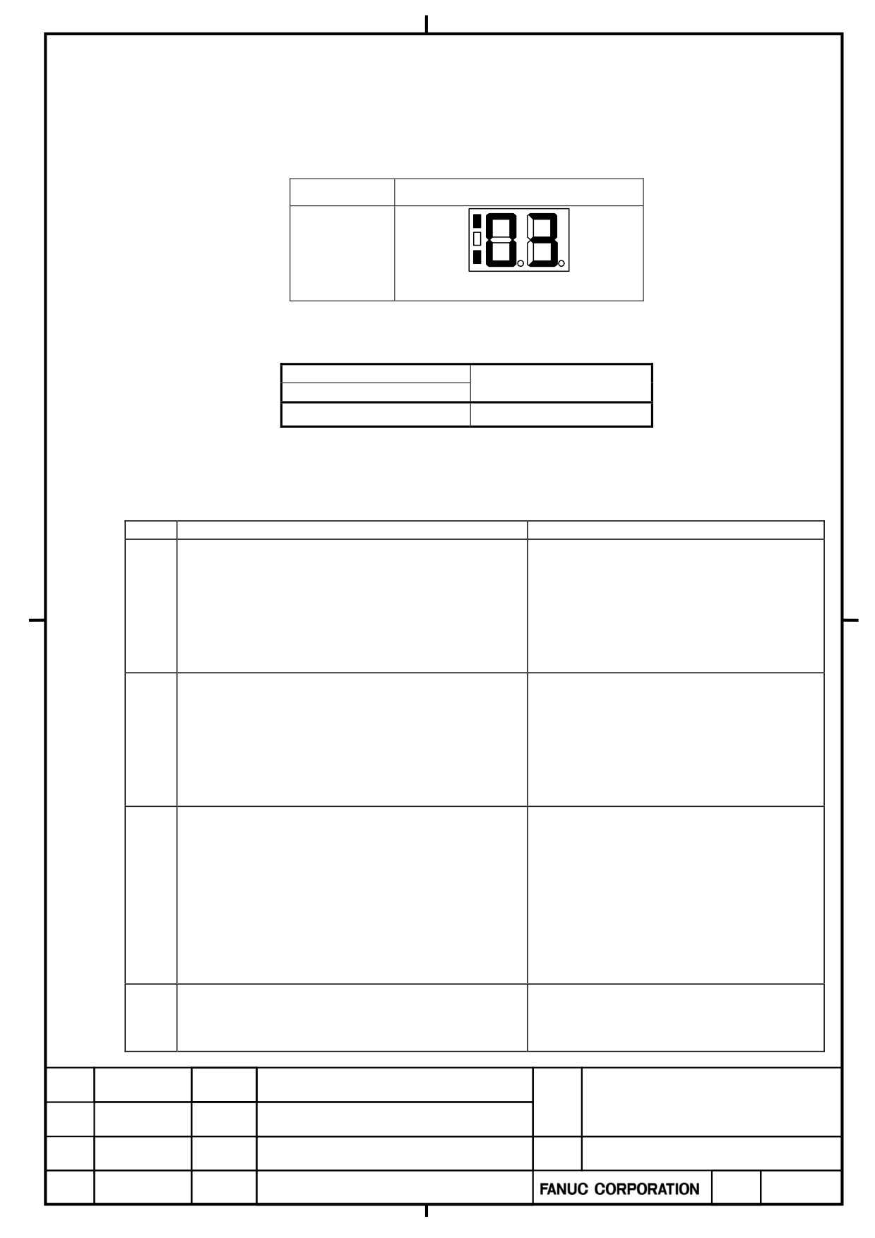
(8) Status Error Indication Function
When a parameter is set incorrectly or a sequence is incorrect, the error LED (orange) on the indicator of
the spindle amplifier (SP) is turned on, and an error code is displayed.
Ex. Display of error indicator
Status
Indicator
Error display
error LED and error code
The error is also displayed on the diagnosis screen of the CNC.
Diagnostic number
Content
FS30i
710
State error number
When the spindle amplifier module does not operate for a certain function, check whether the status error is
indicated in the display section of the SP or the diagnosis screen of the CNC.
No.
Description
Action
Although neither *ESP (emergency stop signal)
(there are two types of signals, a PMC signal and
Check the *ESP and MRDY sequences.
PSM contact signal) nor MRDY (machine ready
For MRDY, pay attention to the parameter
01
signal) has been input, SFR (forward rotation
that specifies whether to use the MRDY
signal), SRV (reverse rotation signal), or ORCM
signal (bit 0 of parameter No. 4001).
(orientation command) is input.
Although parameter settings are such that that there
is no position sensor (position control is not to be
performed, that is, bits 3, 2, 1, and 0 of parameter
03
Check setting of the parameter.
No. 4002 are, respectively, 0, 0, 0, and 0), a Cs axis
contour control command has been issued.
In this case, the motor is not activated.
Although parameter settings are such that that there
is no position sensor (position control is not to be
performed, that is, bits 3, 2, 1, and 0 of parameter
No. 4002 are, respectively, 0, 0, 0, and 0), a servo
04
Check setting of the parameter.
mode (such as rigid tapping or Cs axis control)
command or spindle synchronization control
command has been issued.
In this case, the motor is not activated.
Although optional parameter for the orientation
Check setting of the parameter for
05
function is not set, an ORCM (orientation
orientation.
command) is input.
α+ series SERVO AMPLIFIER
TITLE
for 30+-B Start-up and
Maintenance manual
B-65285EN/03-02/04
NO.
EDT.
DATE
DESIG.
DESCRIPTION
PAGE
29 / 79