FANUC AC SERVO MOTOR ai series, AC SPINDLE MOTOR ai series, SERVO AMPLIFIER ai series. MAINTENANCE MANUAL - page 6
1.MOTOR/DETECTOR/AMPLIFIER MOTOR/DETECTOR/AMPLIFIER
PREVENTIVE MAINTENANCE PREVENTIVE MAINTENANCE
B-65285EN/04
WARNING
•
Do not disassemble the spindle. Particularly, the rotor of a synchronous built-in
spindle motor (BiS Series) uses strong permanent magnets. The strong magnet
force may cause injury or medical appliance malfunction.
•
Do not operate a synchronous built-in spindle motor with an external engine.
Doing so is very dangerous because it makes the motor act as a power generator,
generating high voltage. A power outage is also dangerous because the motor
runs freely and, again, generates high voltage. As a safety precaution, a sub
module SM (SSM) is connected between motor and amplifier. Do not disconnect
the SSM under any circumstances. Also, connect the machine frame to the
ground to prevent electric shock.
•
A synchronous built-in spindle motor may perform a pole position detection
operation when it receives the first rotation command after it is powered on or
recovers from an alarm. The pole position detection operation takes 20 to 60
seconds to complete, during which the spindle behaves oddly, e.g., rotating
clockwise and counterclockwise alternately in rapid succession. This
phenomenon is not abnormal. During the detection operation, do not touch or look
down at the spindle, which is a dangerous act.
CAUTION
Performing a test run described in Chapter 3, "TEST RUN METHOD", in Part IV, of
"FANUC - NSK SPINDLE UNIT series DESCRIPTIONS (B-65352EN)" and the
inspection and maintenance work described in this manual is the condition for
guaranteeing the operation of the FANUC-NSK spindle unit. Be sure to perform
the test run and inspection and maintenance work as instructed.
1.2.4.1 Routine inspection of the FANUC-NSK spindle unit
Perform the following routine inspections every day at the start of operation so that stable performance can
be obtained from the spindle.
Item
Check
1
Check if the axis, when turned manually, rotates lightly and smoothly.
WARNING When turning the axis manually, be sure to turn off the power to the machine.
2
Check if cuttings and coolant residuals are attached to the periphery of a slinger.
3
Check if dust such as cuttings is attached to the spindle taper portion.
4
For operation at 15,000 min-1 or more immediately after power-up, increase the speed gradually
by using the spindle override function. (This substitutes for a simple test run.)
5
Check if an abnormal sound is generated.
6
Check if an abnormal vibration is generated.
7
Check if an abnormal heat is generated.
1.2.4.2 Maintenance of the FANUC-NSK spindle unit
A FANUC-NSK spindle unit with a grease unit requires periodical maintenance for consumable/wear parts,
such as supplying grease. Depending on the use frequency of and damage to parts, maintenance generally
becomes necessary after two years of machine operation or 10,000 hours of spindle operation.
Contact FANUC or the machine tool builder when maintenance becomes necessary. Also, an effective way
to reduce the machine down time due to maintenance is to prepare spare parts; consult with the machine tool
builder.
- 132 -
MOTOR/DETECTOR/AMPLIFIER
1.MOTOR/DETECTOR/AMPLIFIER
B-65285EN/04
PREVENTIVE MAINTENANCE
PREVENTIVE MAINTENANCE
1.2.4.3 Test run of the FANUC-NSK spindle unit
If any of the following cases applies, be sure to contact the machine tool builder and perform a test run as
described in Chapter 3, "TEST RUN METHOD", in Part IV, of "FANUC - NSK SPINDLE UNIT
series DESCRIPTIONS (B-65352EN)".
-
If the spindle unit is rotated for the first time after it is unpacked or attached to the machine
-
If the machine or spindle unit has undergone transportation or relocation
-
If the spindle unit alone has been stored for a period longer than six months or has not been used for
one month or more after installation
CAUTION
FANUC assumes no responsibility for any damage resulting from the failure to perform a
test run or improper use of the spindle unit.
1.2.4.4 Storage method of the FANUC-NSK spindle unit
Apply rust-proof oil to the surface of the spindle unit, pack the spindle unit, and store the packed spindle
unit at a location that satisfies the conditions described below. Also, follow the "This Side Up" and "No Pile
Up" instructions indicated on the pack surface.
-
Indoor well ventilated place not exposed to direct sunlight (place where the temperature varies little,
the room temperature is within 5°C to 40°C, and the humidity is 35% to 85% RH)
-
Place on the shelf subject to little vibration and dust (Do not place the spindle unit directly on the floor;
vibration and dust can damage the bearing or other parts of the spindle.)
Before using the spindle unit after a storage period of one month or more, make necessary checks, such as
measuring winding and insulation resistance, examining the appearance for rust and other problems, and
checking whether the axis can be turned manually. Depending on the storage period, a test run may be
necessary (described earlier).
1.2.5
Preventive Maintenance of a Linear Motor
The magnet plate of a linear motor contains very strong magnets. When performing the maintenance work,
make sure all those engaged in the work fully understand the potential risks involved.
WARNING
• The FANUC linear motors use very strong magnets. Improper handling of the
motor is very dangerous and can lead to a serious accident. Particularly, a person
wearing a pacemaker or other medical apparatus should stay away from the linear
motor; otherwise, the apparatus may malfunction, potentially resulting in a
life-threatening accident.
• Those who will come near or touch a linear motor for maintenance work should
receive safety education in advance. For details, contact the machine tool builder
or FANUC.
1.2.5.1 Appearance inspection of the linear motor (magnet plate)
Perform an appearance inspection as well during cleaning or other maintenance work. A crack, chip,
deformation, or any other abnormality in appearance of the motor can lead to a serious failure in the
not-so-distant future. If you find any such abnormality, be sure to report it to the machine tool builder. A
scratch or other slight scar on the motor surface can also be a sign of future trouble and needs to be
addressed with care. Some suggested appearance inspection items for the magnet plate are described below.
- 133 -
1.MOTOR/DETECTOR/AMPLIFIER MOTOR/DETECTOR/AMPLIFIER
PREVENTIVE MAINTENANCE PREVENTIVE MAINTENANCE
B-65285EN/04
* For the coil slider (the side to which the power line is connected), see "Main inspection items" earlier
in this manual.
Appearance of the magnet plate (which may have a stainless cover)
Appearance inspection item
Measure
Crack or chip in the magnet plate resin
The magnet plate needs to be replaced. If unattended, it can cause
Deformation or bulge of the magnet plate or
trouble in the not-so-distant future. If the problem is extremely
softening of the resin
minor, consult with the machine tool builder or FANUC.
The magnet is exposed, or the resin or
The magnet plate needs to be replaced urgently.
magnet is floating
Foreign matter may have entered into the motor, or interference
Scratch on the magnet plate
between parts is likely. It is necessary to eliminate the cause and
take a measure to prevent recurrence.
Floating, bulging, or deformed stainless
The cover or magnet plate needs to be replaced.
cover
1.2.6
Maintenance of a Detector
CAUTION
• Detectors such as Pulsecoders are precision equipment. When handling a
detector, avoid applying shock to it. Also, exercise care to prevent cutting powder,
dust, cutting fluid, or other foreign matter from attaching to it.
• Make sure that all connectors are connected properly and securely. A connection
failure can cause an alarm or some other problem.
• If the detector and/or connectors are not installed securely, cutting fluid may enter
the inside of the detector, making it necessary to replace the detector. In that case,
contact the machine tool builder or FANUC.
NOTE
If you use a detector not manufactured by FANUC, contact the machine tool
builder or detector manufacturer for detailed information on the detector.
1.2.6.1 Alarms for built-in detectors (αi and βi Pulsecoders) and
troubleshooting actions
These alarms concern built-in detectors that are connected directly to the control unit (CNC/servo
amplifier).
Based on the alarm number and description, take an appropriate action as described in the following
subsection, "Detailed troubleshooting methods".
Detailed
Alarm No.: Alarm
Description
Possible cause
Action
troubleshooting
method
-
Communication
361: ABNORMAL PHASE
error in the
- Pulse coder failure
Replace the
(3)
DATA(INT)
Pulsecoder
- Noise
Pulsecoder.
(4)
-
ID data error
Check the effect
364: SOFT PHASE
- Noise
of noise.
(1)
Position data alarm
ALARM(INT)
- Entry of cutting fluid
Replace the
(3)
Pulsecoder.
Replace the
365: BROKEN LED(INT)
LED disconnection
- Pulse coder failure
(3)
Pulsecoder.
- 134 -

MOTOR/DETECTOR/AMPLIFIER
1.MOTOR/DETECTOR/AMPLIFIER
B-65285EN/04
PREVENTIVE MAINTENANCE
PREVENTIVE MAINTENANCE
Detailed
Alarm No.: Alarm
Description
Possible cause
Action
troubleshooting
method
Small internal signal
- Pulse coder failure
Replace the
(3)
366: PULSE MISS(INT)
amplitude
- Noise
Pulsecoder.
(4)
Position data count
- Pulse coder failure
Replace the
(3)
367: COUNT MISS(INT)
error
- Noise
Pulsecoder.
(4)
- Cable disconnection
Check the cable.
(2)
368: SERIAL DATA
Communication
- Pulse coder failure
Replace the
(3)
ERROR(INT)
interruption
- Noise
Pulsecoder.
(4)
369: DATA TRANS.
Communication data
Check the effect
- Noise
(1)
ERROR(INT)
alarm
of noise.
453: SPC SOFT
Position - pole data
- Pulse coder failure
Replace the
(3)
DISCONNECT ALARM
error
- Entry of cutting fluid
Pulsecoder.
1.2.6.2 Alarms for separate detectors and troubleshooting actions
These alarms concern separate detectors that are connected to the control unit via a separate detector
interface unit (SDU).
Based on the alarm number and description, take an appropriate action as described in the following
subsection, "Detailed troubleshooting methods".
Detailed
Alarm No.: Alarm
Description
Possible cause
Action
troubleshooting
method
380: BROKEN LED(EXT)
LED disconnection
Position data count
382: COUNT MISS(EXT)
error
Replace the
Small internal
- Detector failure
(4)
383: PULSE MISS(EXT)
detector.
signal amplitude
384: SOFT PHASE
Position data alarm
ALARM(EXT)
Check the cable.
- Cable disconnection
Check the effect
(2)
385: SERIAL DATA
Communication
- Noise
of noise.
(1)
ERROR(EXT)
interruption
- Detector failure
Replace the
(4)
detector.
386: DATA TRANS.
Communication
Check the effect
- Noise
(1)
ERROR(EXT)
data alarm
of noise.
381: ABNORMAL PHASE
(EXT)
For details, contact the machine tool builder or detector manufacturer.
387: ABNORMAL
ENCODER(EXT)
1.2.6.3 Detailed troubleshooting methods
(1) Checking the effect of noise
Check CNC diagnosis information No.356 (Built-in detector), No.357 (Separate detector).
Normally, 0 is displayed. However, if the position data from the Pulsecoder becomes unstable due to noise
or some other factor, this value is incremented. The value is cleared when the CNC unit is powered off.
Immediately after the power is turned on, 0 is displayed.
(2) Checking the cable
Check whether the feedback cable is not disconnected and whether the connector is properly plugged.
- 135 -
1.MOTOR/DETECTOR/AMPLIFIER MOTOR/DETECTOR/AMPLIFIER
PREVENTIVE MAINTENANCE PREVENTIVE MAINTENANCE
B-65285EN/04
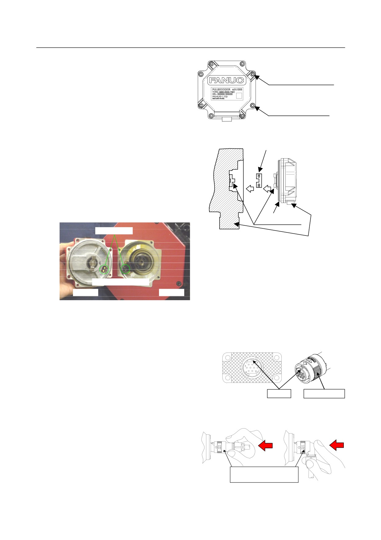
(3) Replacing the Pulsecoder
× Do not loosen
(3)-1 Pulse coder replacement procedure
Bolt fastening the Pulsecoder cover M3
<1> Remove the four M4 hexagon socket head cap
screws fastening the Pulsecoder. The M3 bolts
Bolt fastening the Pulsecoder M4
fastening the Pulsecoder cover do not need to
be loosed. (See the figure at right.)
<2> Remove the Pulsecoder and Oldham's coupling
(see the following figure).
Oldham's coupling
<3> Set the new Pulsecoder and Oldham's coupling on
the motor. Adjust the direction of the mate
Oldham's coupling to that of the Oldham's coupling
so that the teeth are engaged.
Push in the Pulsecoder until the O ring fits in the
joint between the motor and Pulsecoder. Take care
O ring
so that the O ring of the Pulsecoder is not bitten.
Mate Oldham's coupling
Thermistor connector
Adjust the connector direction
Attach the Pulsecoder in such a direction that the
power connector of the servo motor and the feedback
cable of the Pulsecoder face the same direction or that
Adjust the connection parts
the thermistor connection parts of the servo motor
and Pulsecoder match each other (see the figure at
Pulse coder
Servo motor
left).
<4> Fastening the Pulsecoder with the four M4 hexagon socket head cap screws. (Appropriate torque: 1.5
Nm)
(3)-2 Feedback cable plugging procedure
Plug in the feedback cable connector, as instructed in the
procedure below, and check that the connector is securely
connected.
<1> Check the plugging side and key direction.
Main key
Coupling nut
Check that the plugging side is free of foreign matter,
such as dirt or oil.
Straight type
Right angle type
<2> Plug in the feedback cable connector.
Hold the connector, as shown in the figure at
right. Plug in the connector until you hear a
click.
Caution)
Do not hold the coupling nut.
- 136 -
MOTOR/DETECTOR/AMPLIFIER
1.MOTOR/DETECTOR/AMPLIFIER
B-65285EN/04
PREVENTIVE MAINTENANCE
PREVENTIVE MAINTENANCE
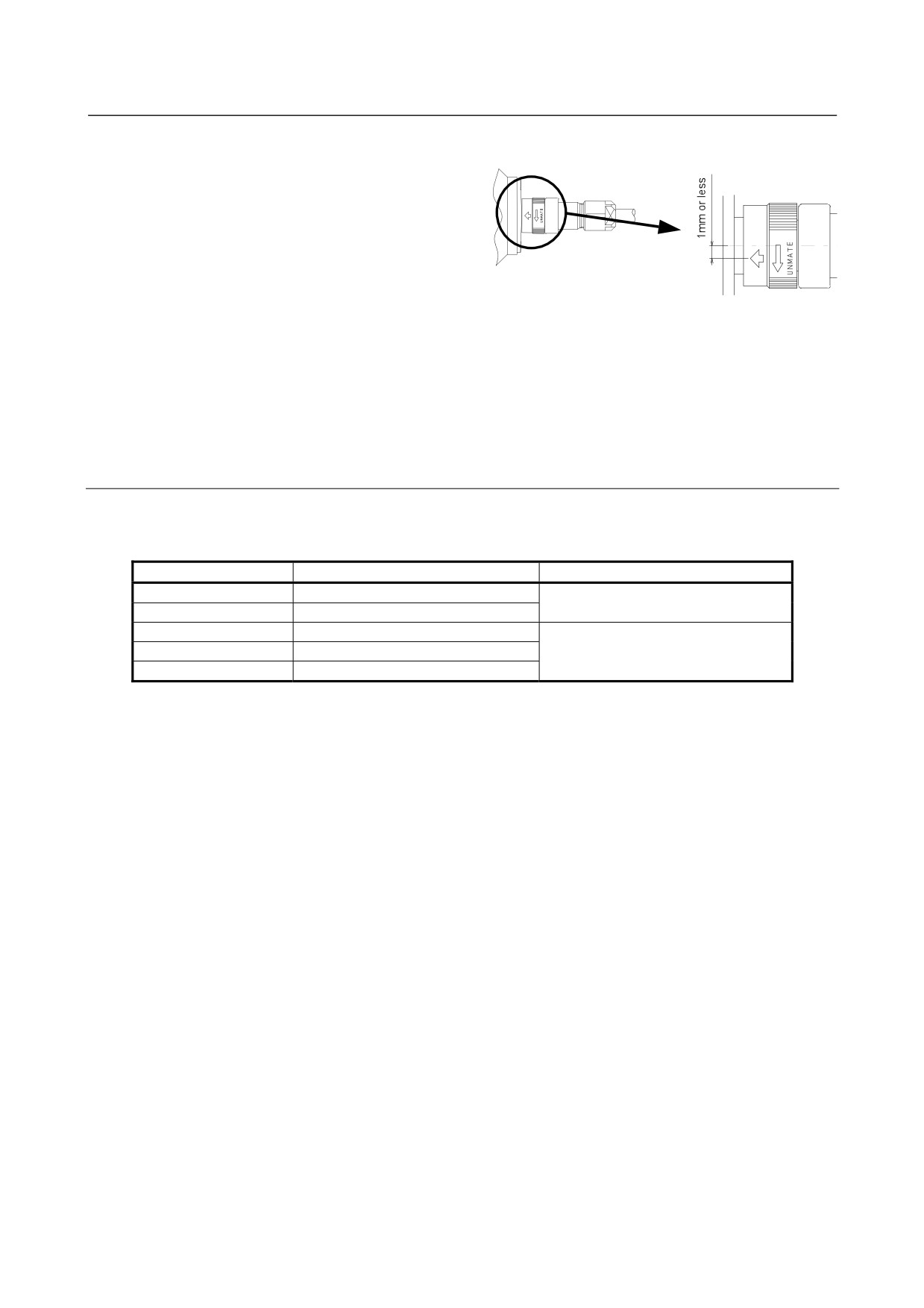
<3> Check the connection condition.
1.
Check that the arrow mark of the
connector is at the center, as shown in
the figure at right. If the arrow mark is
not at the center, turn the coupling nut
manually until the mark comes to the
appropriate position.
2.
Hold the connector by the same part as in <2>, and pull it lightly to check that the connector does
not come off. Do not pull the cable.
(4) If troubleshooting is difficult for the user
If the problem is difficult for the user to troubleshoot because it is due to a detector failure or noise, consult
with the machine tool builder or FANUC.
1.2.6.4 Maintenance of βiS motor Pulsecoders
Problems concerning the Pulsecoders of the motors listed in the table below require the maintenance
(replacement) of the entire motor (it is not possible to maintain the Pulsecoder alone).
Motor model
Motor specification
Remarks
βiS 0.2/5000
A06B-0111-Bx03
x=1,2,4,5
βiS 0.3/5000
A06B-0112-Bx03
βiS 0.4/5000
A06B-0114-Bx03#0y00
x=1,2,4,5 y=0,1
βiS 0.5/6000
A06B-0115-Bx03#0y00
βiS 1/6000
A06B-0116-Bx03#0y00
- 137 -
1.MOTOR/DETECTOR/AMPLIFIER MOTOR/DETECTOR/AMPLIFIER
PREVENTIVE MAINTENANCE PREVENTIVE MAINTENANCE
B-65285EN/04
1.3
PREVENTIVE MAINTENANCE OF SERVO AMPLIFIERS
1.3.1
Warnings, Cautions, and Notes on Operation of Servo
Amplifiers
This subsection contains the safety precautions on preventive maintenance of a servo amplifier (a generic
term to refer to the power supply, servo amplifier, spindle amplifier, and other sub modules of a motor drive
unit). These precautions are classified into "warnings", "cautions", and "notes" according to their bearing on
safety. Make sure that you understand and comply with these precautions when carrying out the
maintenance work.
WARNING
•
Make sure that you are safely dressed and have a safe working environment when
performing preventive maintenance for a servo amplifier.
-
Be dressed safely, e.g. by wearing gloves and safety shoes, to protect against injury due to an
edge or protrusion and electric shock.
-
Have the work done by more than one person, where possible, so that immediate action can be
taken if an accident occurs when handling a motor.
-
A servo amplifier and AC reactor contain heavy components. Be careful when transporting them
or mounting them on the power magnetic cabinet. Also be careful not to get your fingers caught
between the power magnetics cabinet and servo amplifier.
•
Before turning on the power, check that the door of the power magnetics cabinet and
all other doors.
-
Ensure that the door of the power magnetics cabinet containing the servo amplifier, as well as all
other doors, are closed and locked except during maintenance work.
•
When the need arises to open the door of the power magnetics cabinet, only a person
trained in the maintenance of the corresponding machine or equipment should do the
task after shutting off the power supply to the power magnetics cabinet by opening
both the input circuit breaker of the power magnetics cabinet and the factory switch
used to supply power to the cabinet.
•
Be careful about electric shock, fire, and other accidents.
-
If the machine must be operated with the door open for adjustment or some other purpose, the
operator must keep his or her hands and tools well away from any dangerous voltages. Such work
must be done only by a person trained in the maintenance of the machine or equipment.
-
Ensure that the door of the power magnetics cabinet is locked so that the door cannot be opened
by anyone, except service personnel or a qualified person trained in maintenance to prevent
electric shock, when the servo amplifier is powered on.
-
When the need arises for an operator to open the door of the power magnetics cabinet and
perform an operation, ensure that the operator is sufficiently educated in safety or that a
protective cover is added to prevent the operator from touching any dangerous part.
-
The servo amplifier contains a large-capacity electrolytic capacitor in it and remains charged for
a while after the power is shut off. Before touching the servo amplifier for maintenance or some
other purpose, measure the residual voltage of the DC link connection using a tester and check
that the red LED for indicating charging is in progress is not lit, in order to ensure safety.
-
After wiring, be sure to close the servo amplifier cover.
- 138 -
MOTOR/DETECTOR/AMPLIFIER
1.MOTOR/DETECTOR/AMPLIFIER
B-65285EN/04
PREVENTIVE MAINTENANCE
PREVENTIVE MAINTENANCE
-
A loose screw or poor connector contact can cause a motor malfunction or overheating,
connection to ground, or short-circuit. Be extremely careful with power supply lines, motor
power lines, and DC link connections through which a large electric current flows, because a
loose screw or poor connector contact may lead to a fire. Tighten screws and connectors using the
specified screw tightening torque.
-
The surfaces of the regenerative discharge unit and heat radiator may become very hot. Do not
touch them directly by hand.
•
When operating the machine for the first time after preventive maintenance, check
that the machine operates as instructed.
-
To check whether the machine operates as instructed, first specify a small value for the motor and
then increase the value gradually. If the motor operates abnormally, perform an emergency stop
immediately.
-
When pressing the emergency stop button, check that the motor stops immediately and that the
power being supplied to the amplifier is shut off by the magnetic contactor.
•
Notes on alarms
-
If the machine stops due to an alarm, check the alarm number. Depending on the alarm issued, if
the power is supplied without replacing the failed component, another component may be
damaged, making it difficult to identify the original cause of the alarm.
-
Before resetting an alarm, ensure that the original cause of the alarm has been removed.
•
If the motor causes any abnormal noise or vibration while operating, stop it
immediately.
-
Using the motor in spite of the abnormal noise or vibration may damage the servo amplifier.
•
Do not disassemble or modify a servo amplifier.
Do not disassemble or modify a servo amplifier in any way not specified by FANUC; doing so can
lead to a failure.
CAUTION
• Notes on servo amplifier replacement and wiring
-
The work of servo amplifier replacement and wiring should be carried out by a person trained in
the maintenance of the machine and equipment concerned.
-
When replacing a servo amplifier, check that the combination of the amplifier and the motor is
appropriate.
-
Check that the servo amplifier is securely mounted on the power magnetics cabinet. If there is
any clearance between the power magnetics cabinet and the surface on which the amplifier is
mounted, dust entering the gap may hinder the normal operation of the servo amplifier.
-
Ensure that the power supply lines, motor power lines, and signal lines are each connected to the
correct terminal or connector.
-
Unless otherwise instructed, do not unplug a connector and plug it back with the power on; doing
so may cause the servo amplifier to fail.
-
When mounting or unmounting the servo amplifier, exercise care not to get your fingers caught
between the servo amplifier and power magnetics cabinet.
-
Take care not to lose track of removed screws. Turning on the power with any lost screw left in
the unit may damage the machine.
-
Exercise care to prevent the power supply lines and motor power lines from being connected to
the ground or being short-circuited.
-
Protect the lines from any stress such as bending. Handle the line ends appropriately.
- 139 -
1.MOTOR/DETECTOR/AMPLIFIER MOTOR/DETECTOR/AMPLIFIER
PREVENTIVE MAINTENANCE PREVENTIVE MAINTENANCE
B-65285EN/04
•
Be careful about the handling of a servo amplifier.
-
Do not disassemble a servo amplifier. Doing so poses the risk of electric shock, because the
capacitor may remain charged.
-
Do not apply shock to a servo amplifier. Doing so may damage its components, potentially
causing the amplifier to malfunction.
-
Do not apply an excessively large force to plastic parts. If a plastic section breaks, it may damage
internal parts, thus hindering normal operation or leading to a risk of injury due to a broken
section.
•
Be careful about the operating environment of a servo amplifier.
-
Prevent conductive, combustible, or corrosive foreign matter, mist, or drops of water from
entering the inside of the unit. The entry of any such material may cause the unit to explode,
break, malfunction, etc.
-
Exercise care to prevent cutting fluid, oil mist, cutting chips, or other foreign matter from
attaching to the radiator or fan motor exposed to the outside of the power magnetics cabinet.
Otherwise, the servo amplifier may become unable to meet its specifications. The service lives of
the fan motor and semiconductors can also be reduced.
•
Clean the heat sink and fan motor on a regular basis.
-
Replace the filter of the power magnetics cabinet on a regular basis.
-
Before cleaning the heat sink, shut down the power and ensure that the temperature of the heat
sink is as cool as the room temperature. The heat sink is very hot immediately after power
shutdown, touching it may cause burn injury.
-
When cleaning the heat sink by blowing air, be careful about dust scattering. Conductive dust
attached to the servo amplifier or its peripheral equipment can lead to a failure.
NOTE
• Make sure that there is sufficient maintenance clearance around the doors of the
machine and equipment.
• Do not step or sit on the servo amplifier, or do not apply shock to it.
• Do not remove a nameplate from a motor.
-
The nameplate is necessary to identify the servo amplifier during maintenance work.
-
If a nameplate comes off, be careful not to lose it.
NOTE
• This manual is focused on the preventive maintenance work to be performed for a
FANUC servo amplifier. The information contained herein may not apply
depending on the type or configuration of the machine. When reading this manual,
refer to the manual of the machine as well. If you have any questions or doubts, do
not act on your own; please contact the machine tool builder or FANUC.
• For detailed information about a servo amplifier, see the manual list shown earlier
and, if necessary, obtain the latest version of the corresponding manual.
- 140 -
MOTOR/DETECTOR/AMPLIFIER
1.MOTOR/DETECTOR/AMPLIFIER
B-65285EN/04
PREVENTIVE MAINTENANCE
PREVENTIVE MAINTENANCE
1.3.2
Preventive Maintenance of a Servo Amplifier
To use a servo amplifier safely throughout its entire service life, perform daily and periodic inspections.
CAUTION
• The preventive maintenance method differs from machine to machine in many
respects. Depending on the machine in use, it may be difficult for the user to
perform periodic inspection or cleaning. If you are not sure about anything as to
preventive maintenance, consult with the machine tool builder and ensure that you
can perform periodic inspection and cleaning.
• The machine should be used within the scope of specification defined by the
machine tool builder. Using the machine in any way that is outside the specified
scope can reduce the servo amplifier's service life or cause a failure.
Inspection
Inspection interval
Inspection item
Judgment criterion
part
Routine
Periodic
Ambient
Around the power magnetics cabinet: 0°C - 45°C
V
temperature
Inside the power magnetics cabinet: 0°C - 55°C
Humidity
V
90% or below RH (dew condensation not allowed)
There shall be no dust or oil mist attached near the
Dust/oil mist
V
servo amplifier.
The cooling fan shall be operating normally without
Operating
Cooling air path
V
the air flow being interrupted.
environment
- No abnormal noise or vibration shall be present
Abnormal
that has not been experienced in the past.
V
vibration/noise
- Vibration near the servo amplifier shall be 0.5 G
or less.
200-V input type: Within 200 - 240 V
Supply voltage
V
400-V input type: Within 400 - 480 V
There shall be no abnormal noise or smell, and
General
V
there shall be no dust or oil mist attached.
Screw
V
There shall be no loose screw.
- There shall be no abnormal vibration or noise,
Servo
Fan motor (NOTE 1, 2)
V
and the fan blades shall be rotating normally.
amplifier
- There shall be no dust or oil mist attached.
Connector
V
There shall be no loose or broken connector.
There shall be no sign of overheating or sheath
Cable
V
deterioration (discoloration pr crack).
The machine operator's panel or screen shall not
Absolute (NOTE 2)
CNC
V
display the alarm indicating the battery voltage of
Pulse coder battery
the absolute Pulsecoder is low.
Magnetic contactor
V
The contactor shall not rattle or chatter.
External
Ground fault
V
The interrupter shall be able to trip.
equipment
interrupter
AC reactor
V
There shall be no hum.
NOTE
1 Fan motors are periodic-replacement parts. It is recommended to inspect fan
motors on a routine basis and replace them in a preventive manner.
2 Fan motors and batteries are periodic-replacement parts. It is recommended to
keep spare parts.
- 141 -
1.MOTOR/DETECTOR/AMPLIFIER MOTOR/DETECTOR/AMPLIFIER
PREVENTIVE MAINTENANCE PREVENTIVE MAINTENANCE
B-65285EN/04
1.3.3
Maintenance of a Servo Amplifier
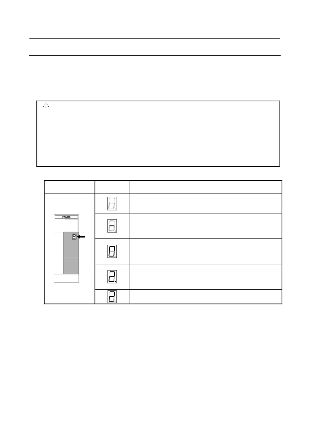
1.3.3.1 Display of the servo amplifier operation status
The STATUS LEDs on the front of the servo amplifier indicate the operation status of the servo amplifier
(whether it is operating normally, the type of alarm, etc.). Use these LEDs for maintenance, inspection,
troubleshooting, etc.
CAUTION
A servo amplifier failure may arise from a combination of multiple causes, in which
case it can be difficult to identify all those causes. Handling the failure in an
improper way may worsen the problem. It is therefore important to analyze the
failure status minutely and identify the true cause or causes of the failure. There
may be cases in which the failure appears to have been fixed but later recurs or
cause a more serious trouble. If you are not sure about the root cause of or
corrective action for a failure, do not act on your own; please contact the machine
tool builder or FANUC for instructions on proper action.
(1) Power supply
STATUS
STATUS LED position
Description
display
The STATUS LED is off.
Control power has not been supplied, cable is faulty, or control power
circuit is defective.
Not ready status
Nameplate
The main circuit is not supplied with power (magnetic contactor is off);
emergency stop state.
When blinking: Power is off.
Ready status
The main circuit is supplied with power (magnetic contactor is on); the
power supply is ready for operation.
When blinking: Power is off.
Warning state (The dot at the lower right lights.)
The power supply has failed; an alarm has occurred after a certain
time of operation.
The warning type is indicated by the character displayed.
Alarm status
The alarm type is indicated by the character displayed.
- 142 -
MOTOR/DETECTOR/AMPLIFIER
1.MOTOR/DETECTOR/AMPLIFIER
B-65285EN/04
PREVENTIVE MAINTENANCE
PREVENTIVE MAINTENANCE
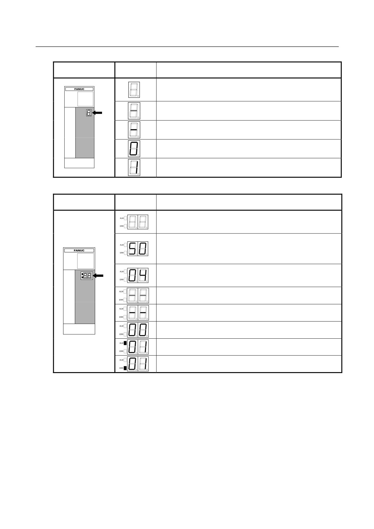
(2) Servo amplifier
STATUS LED
STATUS
Description
position
display
The STATUS LED is off.
Control power has not been supplied, cable is faulty, or control
Nameplate
power circuit is defective.
The control power is short-circuited (- blinks).
Blink
Cable failure
Waiting for the READY signal from the CNC.
Ready status
The servo motor is excited.
Alarm status
The alarm type is indicated by the character displayed.
(3) Spindle amplifier
STATUS LED
STATUS
Description
position
display
The STATUS LED is off.
Control power has not been supplied, cable is faulty, or control
power circuit is defective.
After control power is turned on, the spindle software series is displayed
(for approx. 1 second).
The last two digits of the spindle software series number are
Nameplate
displayed.
The spindle software version is displayed (for approx. 1 second following
the display of the spindle software series).
[Display] 01,02,03,⋅ ⋅ ⋅
→ [Version] A, B, C,⋅ ⋅ ⋅
The CNC is not powered on (- - blinks).
Blink
Blink
Waiting for serial communication and parameter loading completion.
Parameter loading completed
The motor is not excited.
Ready status
The spindle motor is excited.
Alarm status
The alarm type is indicated by the character displayed.
Error status (invalid sequence or parameter setting error)
The error type is indicated by the character displayed.
- 143 -
1.MOTOR/DETECTOR/AMPLIFIER MOTOR/DETECTOR/AMPLIFIER
PREVENTIVE MAINTENANCE PREVENTIVE MAINTENANCE
B-65285EN/04
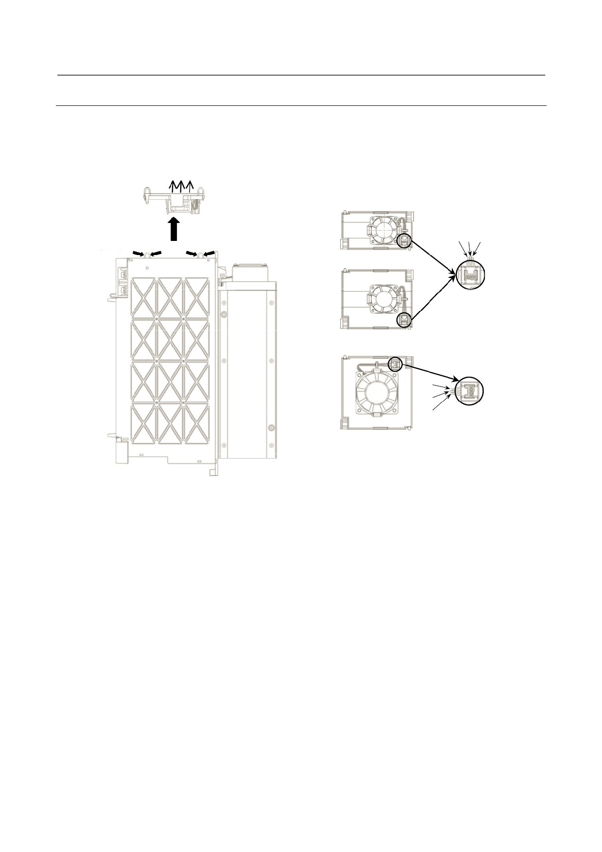
1.3.3.2 Replacement of a fan motor
(1) Fan motor for internal cooling
Replace the internal fan motor, according to the procedure shown in the figure below.
When replacing the fan motor, be careful about the direction of the fan motor (air blow direction), the
direction of the connector, etc.
Air blow direction
Fan unit
(2) Remove the fan
(1) Hold the two tabs
and get the fan unit
unit by pulling it
White Black Red
upward.
off the latch.
Fan unit (60-mm-wide)
Tab
Tab
Be careful about the
connector key direction.
Fan unit (90-mm-wide)
Red
Black
White
Be careful about the
connector key direction.
Fan unit (150-mm-wide)
* Be careful about the fan motor and connector directions.
- 144 -
MOTOR/DETECTOR/AMPLIFIER
1.MOTOR/DETECTOR/AMPLIFIER
B-65285EN/04
PREVENTIVE MAINTENANCE
PREVENTIVE MAINTENANCE
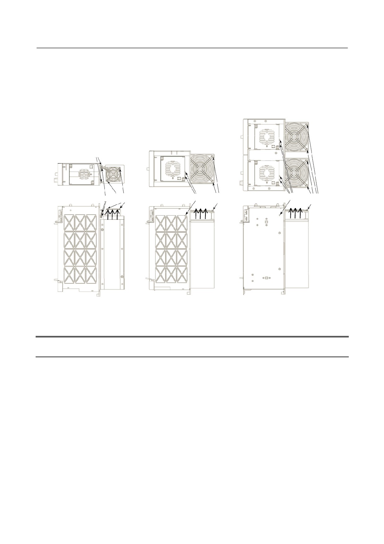
(2) Fan motor for cooling the external radiator
<1> Remove the two sheet metal mounting screws (for the 60-mm-wide model only), and detach the
fan motor from the unit together with the sheet metal.
<2> Remove the fan motor mounting screws (two for one fan motor and four for two fan motors).
<3> Remove the connector mounting screws (two and four for the 300-mm-wide model).
When replacing the fan motor, be careful about the direction of the fan motor (air blow direction), the
direction of the connector, etc.
Sheet metal mounting screws
Fan motor
Fan motor
Fan motor
Connector mounting screw
Connector mounting screw
Connector mounting screw
mounting screw
mounting screw
mounting screw
Air blow
Air blow
Air blow
direction
direction
direction
60 mm wide/90 mm wide
150 mm wide
300 mm wide
1.4
REPLACING BATTERY FOR ABSOLUTE PULSECODERS
1.4.1
Overview
• When the voltage of the batteries for absolute Pulsecoders becomes low, alarm 307 or 306 occurs, with
the following indication in the CNC state display at the bottom of the CNC screen.
Alarm 307 (alarm indicating the voltage of the battery becomes low) :
The indication "APC" blinks in reversed display.
Alarm 306 (battery zero alarm) :
The indication "ALM" blinks in reversed display.
• When alarm 307 (alarm indicating the voltage of the battery becomes low) occurs, replace the battery
as soon as possible. In general, the battery should be replaced within one or two weeks, however, this
depends on the number of Pulsecoders used.
• When alarm 306 (battery zero alarm) occurs, Pulsecoders are reset to the initial state, in which absolute
positions are not held. Alarm 300 (reference position return request alarm) also occurs, indicating that
reference position return is required.
• In general, replace the batteries periodically within the service life listed below.
-
A06B-6050-K061 or D-size alkaline dry cells (LR20) : Two years
(for each six-axis
configuration)
-
A06B-6073-K001 : Two years (for each three-axis configuration)
-
A06B-6114-K504 : One year (for each three-axis configuration)
- 145 -
1.MOTOR/DETECTOR/AMPLIFIER MOTOR/DETECTOR/AMPLIFIER
PREVENTIVE MAINTENANCE PREVENTIVE MAINTENANCE
B-65285EN/04
NOTE
The above values indicate the estimated service life of batteries used with FANUC
absolute Pulsecoders. The actual battery service life depends on the machine
configuration based on, for example, detector types. For details, contact the
machine tool builder.
1.4.2
Replacing Batteries
To prevent absolute position information in absolute Pulsecoders from being lost, turn on the machine
power before replacing the battery. The replacement procedure is described below.
<1> Ensure that the power to the servo amplifier is turned on.
<2> Ensure that the machine is in the emergency stop state (the motor is inactive).
<3> Ensure that the DC link charge LED of the servo amplifier is off.
<4> Detach the old batteries and attach new ones.
The replacement of the batteries in a separate battery case and the replacement of the battery built into the
servo amplifier are described below in detail.
WARNING
• The absolute Pulsecoder of each of the αi/αiS series servo motors and the βiS
series servo motors (βiS0.4 to βiS22) has a built-in backup capacitor. Therefore,
even when the power to the servo amplifier is off and the batteries are replaced,
reference position return is not required if the replacement completes within less
than 10 minutes. Turn the power on and replace the batteries if the replacement
will take 10 minutes or more.
• To prevent electric shock, be careful not to touch metal parts in the power
magnetics cabinet when replacing the batteries.
• Because the servo amplifier uses a large-capacitance electrolytic capacitor
internally, the servo amplifier remains charged for a while even after the power is
turned off. Before touching the servo amplifier for maintenance or other purposes,
ensure your safety by measuring the residual voltage in the DC link with a tester
and confirming that the charge indication LED (red) is off.
• Be sure to replace the batteries with specified ones. Pay attention to the battery
polarity. If a wrong type of battery is used or a battery is installed with incorrect
polarity, the battery may overheat, blow out, or catch fire, or the absolute position
information in the absolute Pulsecoders may be lost.
• Ensure that the battery connector is inserted in the correct position.
1.4.3
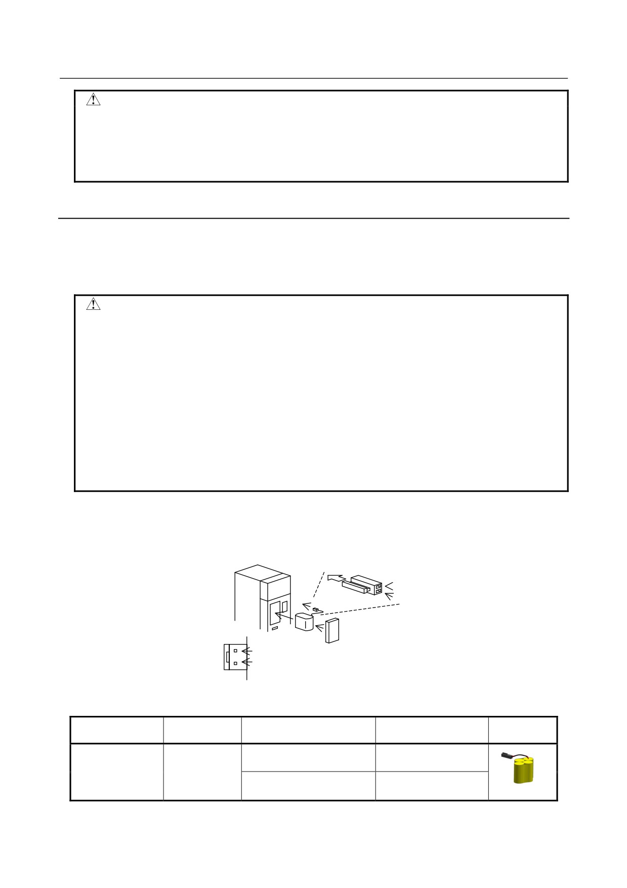
Replacing the Batteries in a Separate Battery Case
Use the following procedure to replace the batteries in the battery case.
<1> Loosen the screws on the battery case and detach the cover.
<2> Replace the batteries in the case (pay attention to the polarity).
<3> Attach the cover to the battery case.
Battery case
(with a cover)
A06B-6050-K060
Batteries
Four A06B-6050-K061 batteries
or D-size alkaline dry cells
- 146 -
MOTOR/DETECTOR/AMPLIFIER
1.MOTOR/DETECTOR/AMPLIFIER
B-65285EN/04
PREVENTIVE MAINTENANCE
PREVENTIVE MAINTENANCE
CAUTION
• Four D-size alkaline dry cells (LR20) that are commercially available can be used
as batteries. A set of four A06B-6050-K061 batteries is optionally available from
FANUC.
• Replace all the four batteries with new ones. If old and new batteries are mixed,
the absolute position information in the absolute Pulsecoders may be lost.
1.4.4
Replacing the Battery Built into the Servo Amplifier
Use the following procedure to replace the special lithium battery.
<1> Detach the battery case.
<2> Replace the special lithium battery.
<3> Attach the battery case.
CAUTION
• Purchase the battery from FANUC because it is not commercially available. It is
therefore recommended that you have a backup battery.
• When the built-in battery is used, do not connect BATL (B3) of connector
CXA2A/CXA2B. Also, do not connect two or more batteries to the same BATL (B3)
line. These connections are dangerous because battery output voltages may be
short-circuited, causing the batteries to overheat.
• Install the battery in the servo amplifier in a direction that allows slack in the cable.
If the battery cable is under tension, a bad connection may occur.
• If the +6 V pin and 0 V pin are short-circuited, the battery may overheat, blow out,
or catch fire, or the absolute position information in the absolute Pulsecoders may
be lost.
• When inserting the connector, align it to the connector pins.
[Connecting the battery]
The battery for the αi series amplifiers is mounted at the front of each of the amplifiers.
[αi series]
Insertion direction
Cable side
Red: +6 V
Connector
Black: 0 V
CX5X
Battery
+6 V
Battery case
0 V
Battery case
[Battery sets and outlines]
Battery ordering
Manufacturer
Battery case ordering
Applicable servo amplifier
Outline
drawing number
model number
drawing number
αi series 60/90 mm width
A06B-6114-K505
A06B-6114-K504
BR-2/3AGCT4A
(Note)
(Panasonic)
αi series 150/300 mm width
A06B-6114-K506
- 147 -
1.MOTOR/DETECTOR/AMPLIFIER MOTOR/DETECTOR/AMPLIFIER
PREVENTIVE MAINTENANCE PREVENTIVE MAINTENANCE
B-65285EN/04
NOTE
When using an old-type battery BR-CCF2TH, order a battery case applicable for
battery A06B-6114-K504.
Used batteries
Old batteries should be disposed as "INDUSTRIAL WASTES" according to the regulations of the country
or autonomy where your machine has been installed.
- 148 -
1.SERVO MOTOR
B-65285EN/04
MOTOR MAINTENANCE
MAINTENANCE
1 SERVO MOTOR MAINTENANCE
1.1
SERVO MOTOR MAINTENANCE PARTS
1.1.1
Pulsecoder
The following lists the ordering specification numbers for maintenance.
(1) Pulsecoder: ordering specification
Motor model
Motor specification
Pulsecoder: ordering specification
X=0
A860-2000-T301
αiA1000
Standard specification
A06B-02aa-BccX
X=1
A860-2005-T301
αiI1000
Standard specification
(aa, cc : Any)
αiS series
X=2
A860-2001-T301
αiA16000 Standard specification
αiF series
X=0
A860-2000-T321
αiA1000
IP67 specification
A06B-02aa -BccX #0100
X=1
A860-2005-T321
αiI1000
IP67 specification
(aa, cc : Any)
X=2
A860-2001-T321
αiA16000 IP67 specification
(2) Oldham's coupling: ordering specification
Motor model
Motor specification
Oldham's coupling: ordering specification
αiS series
A06B-02aa-BccX
A290-0501-V535
αiF series
(aa, cc, X : Any)
- 151 -

1.SERVO MOTOR
MAINTENANCE
MOTOR MAINTENANCE
B-65285EN/04
1.1.2
Cooling Fan
The following lists the ordering specification numbers of cooling fan units.
αiS 50 with Fan, αiS 60 with Fan, αiF 40 with Fan
Fan unit: ordering
Motor model
Model name
Motor specification
Remark
specification
A06B-0275-BXaX
αiS 50/3000 with Fan
A06B-0276-BXaX
αiS 50/3000HV with Fan
(X :Any, a=1 or 3)
αiS series
A06B-0278-BXaX
200VAC
αiS 60/3000 with Fan
A06B-0241-K053
αiF series
A06B-0279-BxaX
1-phase
αiS 60/3000HV with Fan
(X :Any, a=1 or 3)
A06B-0257-BXaX
αiF 40/3000 with Fan
(X :Any, a=1 or 3)
αiS 100 to αiS 500
Fan unit: ordering
Motor model
Model name
Motor specification
Remark
specification
αiS 100/2500 with Fan
A06B-0285-BX1X
αiS 200/2500 with Fan
A06B-0288-BX1X
200VAC
αiS 300/2000
A06B-0292-BX1X
A290-0281-V053
3-phase
αiS 500/2000
A06B-0295-BX1X
(X : Any)
A06B-0286-BX1X
αiS series
αiS 100/2500HV with Fan
A06B-0289-BX1X
αiS 200/2500HV with Fan
A06B-0293-BX1X
αiS 300/2000HV
400VAC
A06B-0290-BX1X
A290-0281-V054
αiS 300/3000HV
3-phase
A06B-0296-BX1X
αiS 500/2000HV
A06B-0297-BX1X
αiS 500/3000HV
(X : Any)
αiS 1000HV to αS 3000HV
Fan unit: ordering
Motor model
Model name
Motor specification
Remark
specification
A06B-0298-BX1X
αiS 1000/2000HV
A290-0298-V054
(X : Any)
A06B-0098-BXXX
αiS 1000/2000HV
A290-0098-V051
(X : Any)
AC400V
αiS series
A06B-0099-BXXX
αiS 1000/3000HV
A290-0098-V050
3-phase
(X : Any)
A06B-0091-BX4X
αiS 2000/2000HV
A06B-0092-BX4X
A290-0091-T054
αiS 3000/2000HV
(X : Any)
- 152 -
1.SERVO MOTOR
B-65285EN/04
MOTOR MAINTENANCE
MAINTENANCE
1.2
REPLACING COOLING FANS
This section describes how to replace cooling fan units.
For each motor, replace the cooling fan unit according to the procedure.
CAUTION
Before replacing a fan motor, remove the power lead to the fan motor and check
that the rotation of the fan motor stops.
If the load on the fan motor is high or an invalid phase sequence is made for a
3-phase fan motor, the fan motor may overheat and stop. If the power lead is
connected, the fan motor suddenly starts rotating when recovered from
overheating.
1.2.1
Replacing a Cooling Fan
1.2.1.1 αiS 50 with Fan, αiS 60 with Fan, and αiF 40 with Fan
(1) Removing a cooling fan unit
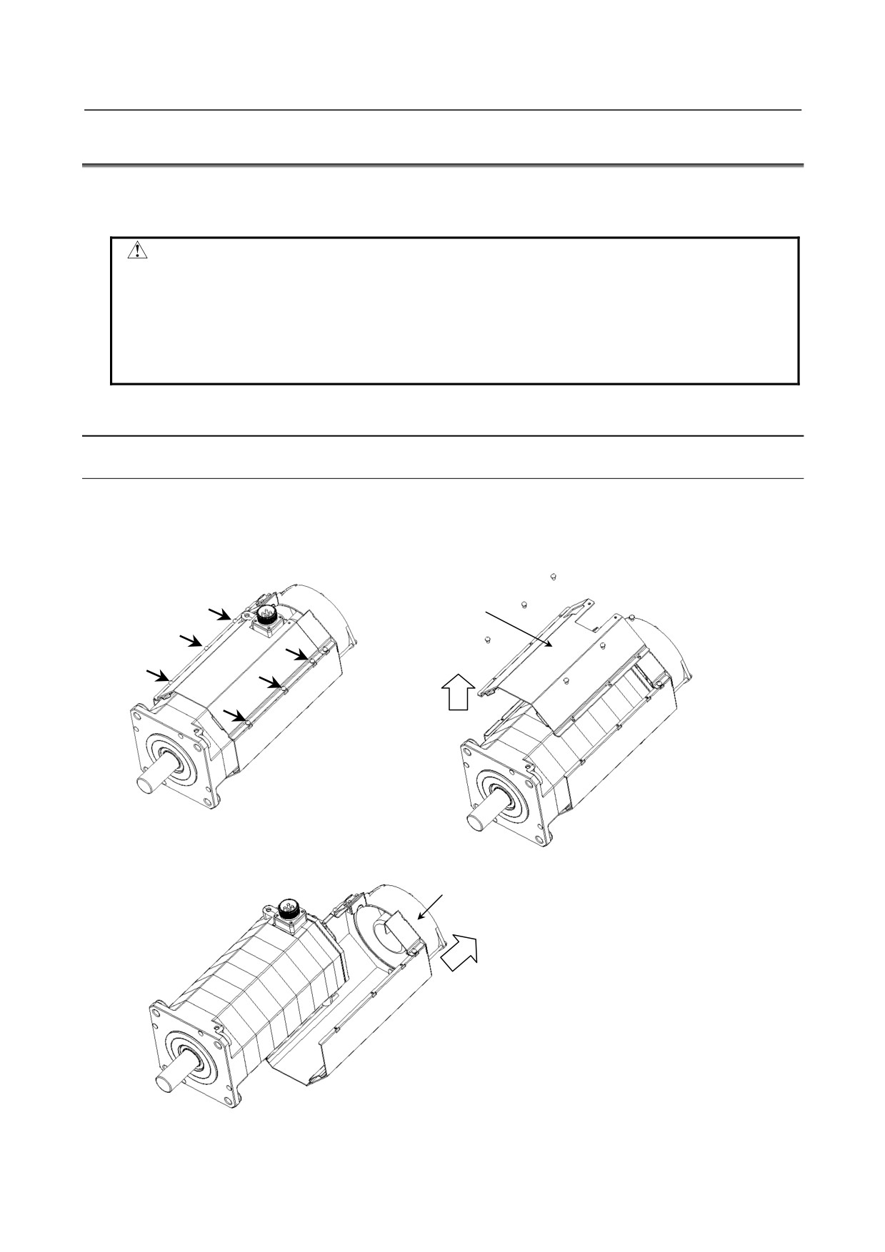
<1> Remove six M6 pan head machine screws fastening the fan cover and remove the front fan cover.
You need only to loosen the pan head machine screws indicated by the arrow in the figure.
M6 pan head
Fan cover
machine screw
<2> Remove the cooling fan unit from the motor.
Cooling fan unit
- 153 -
1.SERVO MOTOR
MAINTENANCE
MOTOR MAINTENANCE
B-65285EN/04
(2) Mounting a cooling fan unit
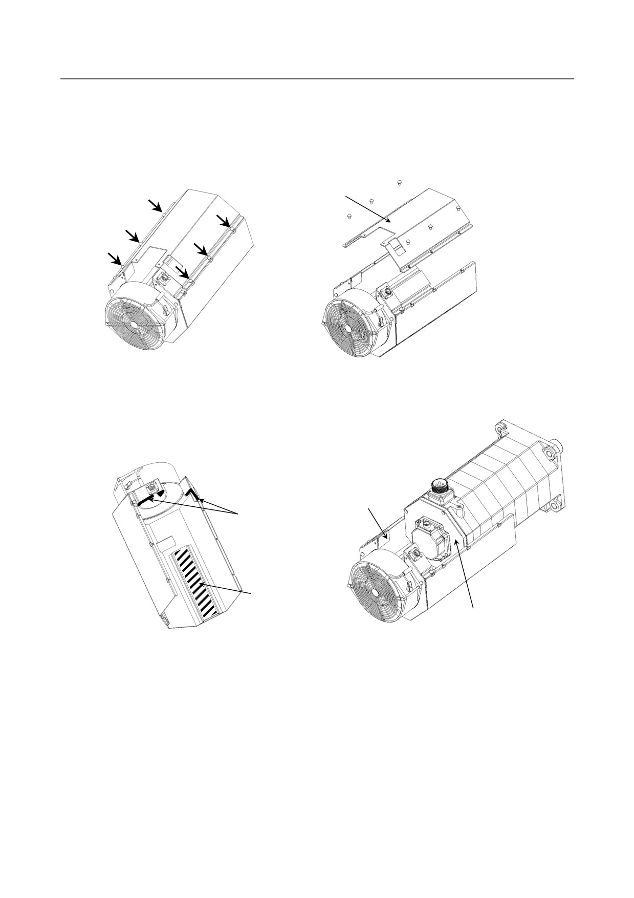
<1> Remove six M6 pan head machine screws from a new cooling fan unit and remove the front fan
cover.
You need only to loosen the pan head machine screws indicated by the arrow in the figure.
M6 pan head
Fan cover
machine screw
<2> Assemble the cooling fan unit and motor.
Align the inside of the sheet metal of the cooling fan unit with the side of the motor and touch the
end of the sheet metal with the back of the motor. (See the figure below.)
Cooling fan unit
End of sheet metal
Inside of sheet metal
Back of motor
- 154 -
1.SERVO MOTOR
B-65285EN/04
MOTOR MAINTENANCE
MAINTENANCE
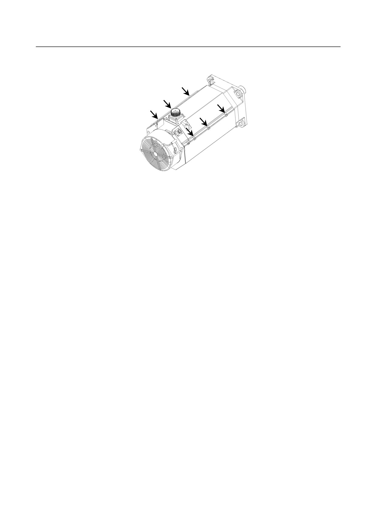
<2> Mount the fan cover and tighten the six M6 pan head machine screws.
(Appropriate torque: 2.5 to 2.8 Nm)
M6 pan head
machine screw
- 155 -
1.SERVO MOTOR
MAINTENANCE
MOTOR MAINTENANCE
B-65285EN/04
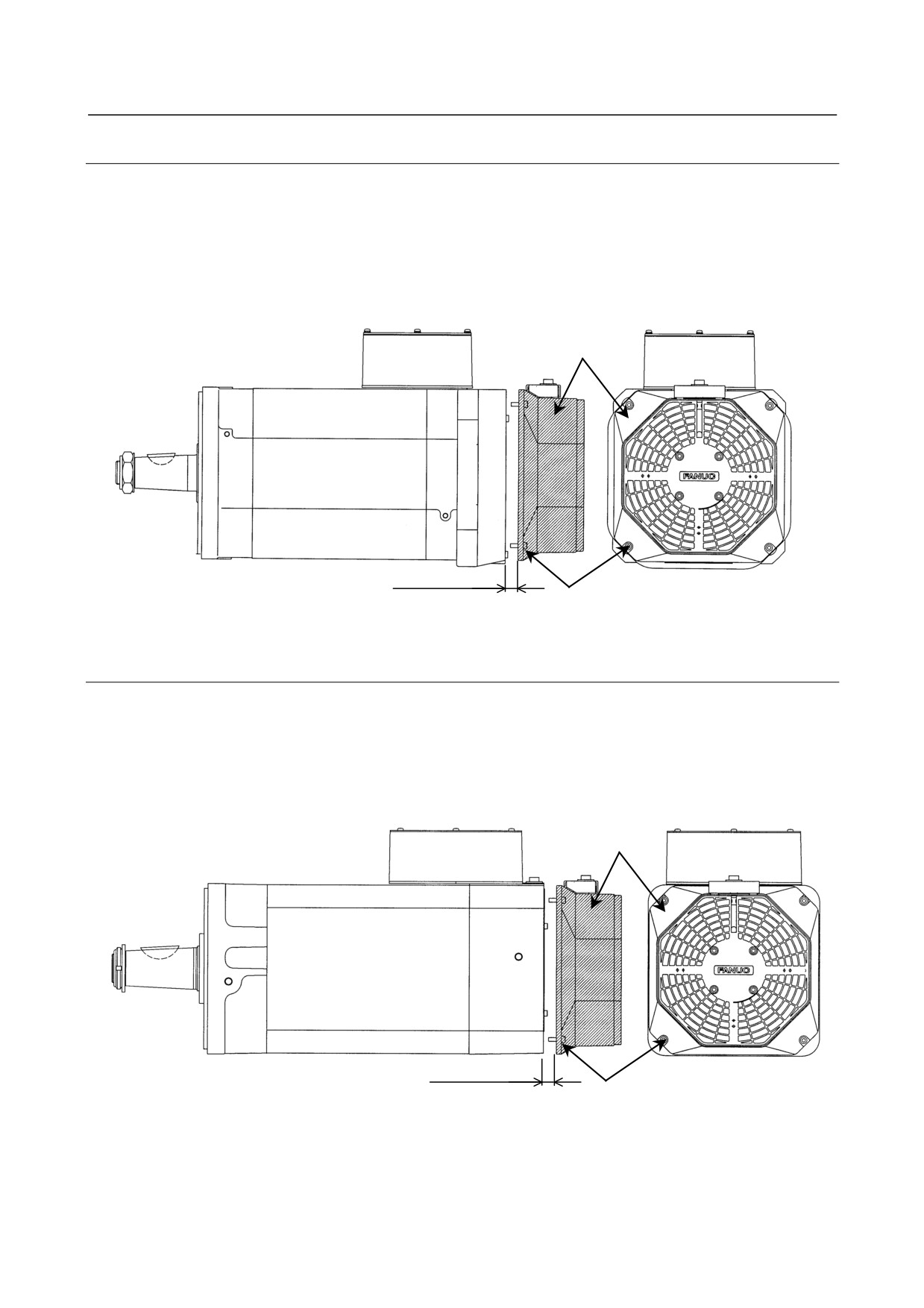
1.2.1.2 αiS 100 with Fan and αiS 200 with Fan (including HV)
(1) Removing a cooling fan unit
Remove the four M6 hexagon socket head cap screws fastening the fan unit and remove the fan unit.
(2) Mounting a cooling fan unit
Apply adhesive for fastening (moderate strength) to the four M6 hexagon socket head cap screws and
mount the fan unit. (Appropriate torque: 3.0 to 3.5 Nm)
Fan unit
Move backward by at least 5 mm.
M6x20 (4 screws)
1.2.1.3 αiS 300 and αiS 500 (including HV)
(1) Removing a cooling fan unit
Remove the four M6 hexagon socket head cap screws fastening the fan unit and remove the fan unit.
(2) Mounting a cooling fan unit
Apply adhesive for fastening (moderate strength) to the four M6 hexagon socket head cap screws and
mount the fan unit. (Appropriate torque: 3.0 to 3.5 Nm)
Fan unit
Move backward by at least 7 mm
M6x20 (4 screws)
- 156 -
1.SERVO MOTOR
B-65285EN/04
MOTOR MAINTENANCE
MAINTENANCE
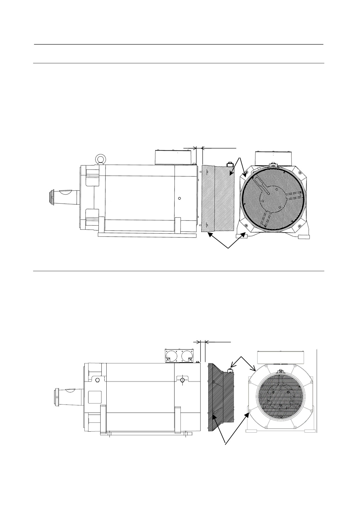
1.2.1.4 αiS 1000HV
(1) Removing a cooling fan unit
Remove the four hexagon socket head cap screws fastening the fan unit and remove the fan unit.
M6x40: 4 screws (A06B-0298-BXXX)
M10x40: 4 screws (A06B-0098-BXXX, A06B-0099-BXXX)
(2) Mounting a cooling fan unit
Apply adhesive for fastening (moderate strength) to the four hexagon socket head cap screws and
mount the fan unit.
Appropriate torque: 9.6 to 13Nm (M6), 19 to 26Nm (M10)
Move backward by at least 15 mm
Fan unit
M6x40 or M10x40
1.2.1.5 αiS 2000HV and αiS 3000HV
(1) Removing a cooling fan unit
Remove the eight M6 hexagon socket head cap screws fastening the fan unit and remove the fan unit.
(2) Mounting a cooling fan unit
Apply adhesive for fastening (moderate strength) to the eight M6 hexagon socket head cap screws and
mount the fan unit. (Appropriate torque: 9.6 to 13 Nm)
Move backward by at least 8 mm
Fan unit
M6x40 (8 screws)
- 157 -
2.SPINDLE MOTOR
MAINTENANCE PARTS
MOTOR MAINTENANCE
B-65285EN/04
2 SPINDLE MOTOR MAINTENANCE PARTS
2.1
MAINTENANCE PARTS
(1) Parts of the terminal box (αiI, αiIP, and αCi series 200V type)
Model
Terminal box assembly
Lid of terminal box
αiI 1/10000, αiI 1/15000
αiI 1.5/10000, αiI 1.5/20000
A290-1402-T400
A290-1402-V410
αC1/6000i
αiI 2/10000, αiI 2/20000
αiI 3/10000, αiI 3/12000
A290-1404-T400
A290-1402-V410
αC2/6000i, αC3/6000i
αiI 6/10000 to αiI 15/7000
αiI 6/12000 to αiI 15/12000
αiIP 12/6000 to αiIP 22/6000
A290-1406-T400
A290-1406-V410
αiIP 12/8000 to αiIP 22/8000
αC6/6000i to αC15/6000i
αiI 18/7000, αiI 22/7000
A290-1410-T400
A290-1410-V410
αiI 18/10000, αiI 22/10000
A290-1410-T401
A290-1410-V410
αiIP 30/6000 to αiIP 50/6000
αiI 30/6000, αiI 40/6000
A290-1412-T400
A290-1040-V402
αiI 50/5000
A290-1414-T400
A290-1040-V402
αiIP 60/5000
A290-0833-T400
A290-1040-V402
NOTE
The above table may not apply to motors of which motor drawing number ends
with B9xx. Contact your FANUC service representative.
(2) Parts of the terminal box (αiIT and αiIL series 200V type)
Model
Terminal box assembly
Lid of terminal box
αiIT 1.5/20000
A290-1402-T400
A290-1402-V410
αiIT 2/20000, αiIT 3/12000
A290-1404-T400
A290-1402-V410
αiIT 6/12000, αiIT 8/12000
A290-1406-T400
A290-1406-V410
αiIT 8/15000, αiIT 15/10000
αiIT 15/15000
A290-1410-T402
A290-1410-V410
αiIT 22/10000
A290-1410-T401
A290-1410-V410
αiIL 8/20000
A290-1487-T400
A290-1406-V410
αiIL 15/15000, αiIL 26/15000
A290-1489-T400
A290-1410-V410
NOTE
The above table may not apply to motors of which motor drawing number ends
with B9xx. Contact your FANUC service representative.
- 158 -
2.SPINDLE MOTOR
B-65285EN/04
MOTOR MAINTENANCE
MAINTENANCE PARTS
(3) Parts of the terminal box (αiI and αiIP series 400V type)
Model
Terminal box assembly
Lid of terminal box
αiI 1/10000HV, αiI 1.5/10000HV
A290-1502-T400
A290-1402-V410
αiI 2/10000HV, αiI 3/10000HV
A290-1504-T400
A290-1402-V410
αiI 6/10000HV to αiI 22/7000HV
A290-1406-T400
A290-1406-V410
αiIP 15/6000HV, αiIP 22/6000HV
αiIP 40/6000HV, αiIP 50/6000HV
A290-1410-T401
A290-1410-V410
αiI 30/6000HV, αiI 40/6000HV
A290-1412-T400
A290-1040-V402
αiI 50/5000HV
A290-1414-T400
A290-1040-V402
αiI 60/5000HV, αiIP 60/5000HV
A290-0860-T403
A290-1040-V402
αiI 75/5000HV
A290-1516-T400
A290-1040-V402
αiI 100/5000HV
A290-1516-T410
A290-1040-V402
αiI 100/5000HV(Large terminal box type)
A290-1532-T410
A290-1532-V402
αiI 100/4000HV
A290-0884-T401
A290-1040-V402
αiI 150/5000HV
A290-1532-T400
A290-1532-V402
NOTE
The above table may not apply to motors of which motor drawing number ends
with B9xx. Contact your FANUC service representative.
(4) Parts of the terminal box (αiIT and αiIL series 400V type)
Model
Terminal box assembly
Lid of terminal box
αiIT 1.5/20000HV
A290-1502-T400
A290-1402-V410
αiIT 2/20000HV, αiIT 3/12000HV
A290-1504-T400
A290-1402-V410
αiIT 6/12000HV, αiIT 8/12000HV
A290-1406-T400
A290-1406-V410
αiIT 15/15000HV, αiIT 22/10000HV
αiIL 8/20000HV
A290-1597-T400
A290-1406-V410
αiIL 15/15000HV, αiIL 26/15000HV
A290-1595-T400
A290-1410-V410
NOTE
The above table may not apply to motors of which motor drawing number ends
with B9xx. Contact your FANUC service representative.
- 159 -
2.SPINDLE MOTOR
MAINTENANCE PARTS
MOTOR MAINTENANCE
B-65285EN/04
(5) Fan motor parts (αiI, αiIP, and αCi series 200V type)
Exhaust
Model
Fan assembly (*1)
Fan cover
Fan motor
direction
αiI 1/10000, αiI 1/15000
A290-1402-T500
A90L-0001-0537/R
Rear
αiI 1.5/10000, αiI 1.5/20000
A290-1402-X501
αC1/6000i
A290-1402-T501
A90L-0001-0537/F
Front
αiI 2/10000, αiI 2/20000
A290-1404-T500
A90L-0001-0538/R
Rear
αiI 3/10000, αiI 3/12000
A290-1404-X501
αC2/6000i, αC3/6000i
A290-1404-T501
A90L-0001-0538/F
Front
αiI 6/10000, αiI 8/8000
A290-1406-T500
A90L-0001-0515/R
Rear
αiI 6/12000, αiI 8/10000
A290-1406-X501
αiI 8/12000
A290-1406-T501
A90L-0001-0515/F
Front
αC6/6000i, αC8/6000i
αiI 12/7000 to αiI 22/7000
αiI 12/10000 to αiI 22/10000
A290-1408-T500
A90L-0001-0548/R
Rear
αiIP 12/6000 to αiIP 22/6000
A290-1408-X501
αiIP 12/8000 to αiIP 22/8000
A290-1408-T501
A90L-0001-0548/F
Front
αC12/6000i to αC22/6000i
αiI 30/6000, αiI 40/6000 (*2)
A290-1412-T510
-
-
Rear
αiIP 30/6000 to αiIP 50/6000 (*2)
A290-1412-T511
-
-
Front
A290-1414-T510
-
-
Rear
αiI 50/5000 (*2)
A290-1414-T511
-
-
Front
A290-0832-T510
-
-
Rear
αiIP 60/5000 (*2)
A290-0832-T511
-
-
Front
NOTE
1 These drawing numbers include fan motors.
2 In case of exchange these fan motors, please change fan assembly (fan motor
with fan cover) unit.
3 The above table may not apply to motors of which motor drawing number ends
with B9xx. Contact your FANUC service representative.
(6) Fan motor parts (αiIT series 200V type)
Model name
Fan assembly (*1)
Fan cover
Fan motor
αiIT 1.5/20000
A290-1463-T500
A290-1402-X501
A90L-0001-0537/RL
αiIT 2/20000, αiIT 3/12000
A290-1464-T500
A290-1404-X501
A90L-0001-0538/RL
αiIT 6/12000
A290-1466-T500
A290-1406-X501
A90L-0001-0515/RL
αiIT 8/12000, αiIT 8/15000
αiIT 15/10000, αiIT 15/15000
A290-1469-T500
A290-1408-X501
A90L-0001-0548/RL
αiIT 22/10000
NOTE
1 These drawing numbers include fan motors.
2 The above table may not apply to motors of which motor drawing number ends
with B9xx. Contact your FANUC service representative.
- 160 -
2.SPINDLE MOTOR
B-65285EN/04
MOTOR MAINTENANCE
MAINTENANCE PARTS
(7) Fan motor parts (αiI and αiIP series 400V type)
Exhaust
Model
Fan assembly (*1)
Fan cover
Fan motor
direction
A290-1502-T500
A90L-0001-0539/R
Rear
αiI 1/10000HV, αiI 1.5/10000HV
A290-1402-X501
A290-1502-T501
A90L-0001-0539/F
Front
A290-1504-T500
A90L-0001-0540/R
Rear
αiI 2/10000HV, αiI 3/10000HV
A290-1404-X501
A290-1504-T501
A90L-0001-0540/F
Front
A290-1506-T500
A90L-0001-0519/R
Rear
αiI 6/10000HV, αiI 8/8000HV
A290-1406-X501
A290-1506-T501
A90L-0001-0519/F
Front
αiI 12/7000HV, αiI 15/7000HV
A290-1508-T500
A90L-0001-0549/R
Rear
αiI 22/7000HV
A290-1408-X501
αiIP 15/6000HV, αiIP 22/6000HV
A290-1508-T501
A90L-0001-0549/F
Front
αiI 30/6000HV, αiI 40/6000HV (*2)
A290-1512-T510
-
-
Rear
αiIP 40/6000HV, αiIP 50/6000HV(*2)
A290-1512-T511
-
-
Front
αiI 60/5000HV (*2)
A290-0883-T510
-
-
Rear
αiIP 60/5000HV (*2)
A290-0883-T511
-
-
Front
A290-1514-T510
-
-
Rear
αiI 50/5000HV (*2)
A290-1514-T511
-
-
Front
αiI 75/5000HV, αiI 100/5000HV (*2)
A290-1516-T500
-
-
Rear
A290-0780-T512
-
-
Pedestal-side
A290-0780-T514
-
-
intake
αiI 100/4000HV (*2)
A290-0780-T513
-
-
Pedestal-side
A290-0780-T515
-
-
exhaust
A290-0884-T500
-
-
Rear
αiI 150/5000HV (*2)
A290-1532-T500
-
-
Rear
NOTE
1 These drawing numbers include fan motors.
2 In case of exchange these fan motors, please change fan assembly (fan motor
with fan cover) unit.
3 The above table may not apply to motors of which motor drawing number ends
with B9xx. Contact your FANUC service representative.
(8) Fan motor parts (αiIT series 400V type)
Model name
Fan assembly (*1)
Fan cover
Fan motor
αiIT 1.5/20000HV
A290-1563-T500
A290-1402-X501
A90L-0001-0539/RL
αiIT 2/20000HV, αiIT 3/12000HV
A290-1564-T500
A290-1404-X501
A90L-0001-0540/RL
αiIT 6/12000HV, αiIT 8/15000HV
A290-1566-T500
A290-1406-X501
A90L-0001-0519/RL
αiIT 15/15000HV, αiIT 22/10000HV
A290-1569-T500
A290-1408-X501
A90L-0001-0549/RL
NOTE
1 These drawing numbers include fan motors.
2 The above table may not apply to motors of which motor drawing number ends
with B9xx. Contact your FANUC service representative.
- 161 -
A.MEASURING SERVO MOTOR
B-65285EN/04
APPENDIX
WAVEFORMS (TCMD, VCMD)
A MEASURING SERVO MOTOR
WAVEFORMS (TCMD, VCMD)
To use a servo motor in a good performance condition for a long time and prevent any failure from
occurring, the TCMD and VCMD waveforms of the servo motor can be checked as diagnosis.
(1) Observation of torque command (TCMD) and speed command (VCMD) waveforms
Check whether there is no abnormality in the waveforms.
For how to measure the TCMD and VCMD waveforms, refer to the FANUC AC SERVO MOTOR αi
series Parameter Manual (B-65270EN).
The waveforms vary according to the operating conditions such as load and cutting speed. Note that
you should make comparisons under the same condition (for example, during fast traverse to the
reference position or low-speed cutting).
(2) Diagnosis by waveforms
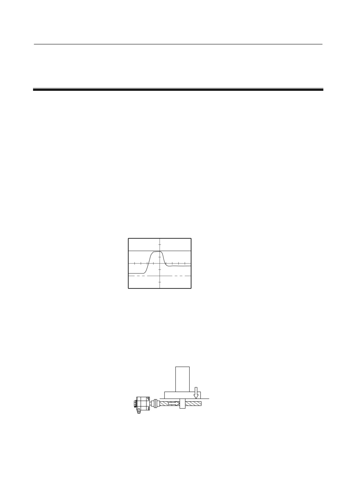
Check the measured waveforms to see whether:
<1> The peak current is within the limit to the current in the amplifier during rapid traverse,
acceleration, or deceleration.(TCMD)
The limit to the amplifier current is listed below.
Limit to the amplifier
current
Measured waveform
(TCMD)
0
Ö The motor used to accelerate/ decelerate with the amplifier current within the limit (the
acceleration/deceleration torque used to be sufficient), but something is wrong now. If this
is the case, the probable causes are:
• The load conditions in the machine have changed because of changed friction or reduced
machine efficiency after long period of use.
• Motor failure
Increased friction
Reduced efficiency
- 165 -
A.MEASURING SERVO MOTOR
WAVEFORMS (TCMD, VCMD)
APPENDIX
B-65285EN/04
[Table 1]
Models
Current value
αiS2/5000HV, αiS2/6000HV, αiS4/5000HV, αiS4/6000HV
10Ap
αiS2/5000, αiS2/6000, αiS4/5000, αiS4/6000
20Ap
αiF1/5000, αiF2/5000, αiF4/4000HV, αiF8/3000HV
αiS8/4000HV, αiS8/6000HV, αiS12/4000HV,
40Ap
αiF4/4000, αiF8/3000, αiF12/3000HV, αiF22/3000HV,
αiS8/4000, αiS8/6000, αiS12/4000, αiS12/6000HV, αiS22/4000HV, αiS22/6000HV,
αiS30/4000HV, αiS40/4000HV, αiS50/2000HV, αiS60/2000HV,
80Ap
αiF12/3000, αiF 22/3000,
αiS12/6000, αiS22/4000, αiS22/6000, αiS30/4000, αiS40/4000, αiS50/2000, αiS60/2000,
160Ap
αiF30/3000, αiF40/3000, αiF40/3000 with fan
αiS50/3000HV with fan,
180Ap
αiS100/2500HV, αiS100/2500HV with fan, αiS 200/2500HV, αiS 200/2500HV with fan
αiS50/3000 with fan,
αiS100/2500, αiS100/2500 with fan, αiS200/2500, αiS200/2500 with fan,
360Ap
αiS300/2000HV, αiS500/2000HV
αiS300/3000HV, αiS500/3000HV
540Ap
αiS300/2000, αiS500/2000, αiS1000/2000HV
360Ap x 2 (Note)
αiS1000/3000HV, αiS2000/2000HV, αiS3000/2000HV
360Ap x 4 (Note)
NOTE
More than one Servo Amplifier is used for one motor.
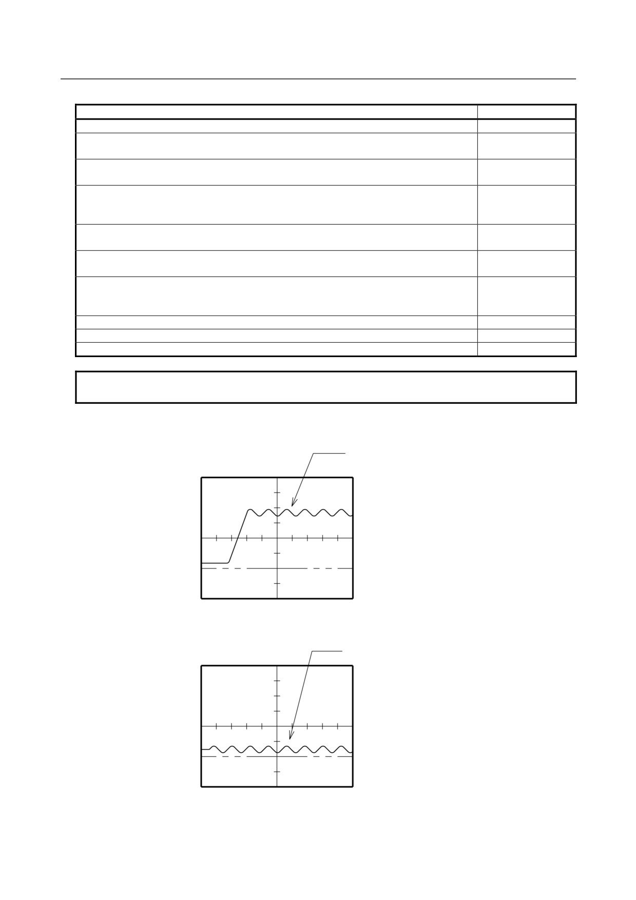
<2> The waveform has ripple during constant-speed feeding (VCMD).
Ripple
Measured waveform
(VCMD)
0
<3> The current waveform has ripple or jumps when the motor is not rotating (VCMD).
Ripple
Measured waveform
(VCMD)
0
If you find anything unusual in relation to the above items <1> to <3>, contact your FANUC service
staff.
- 166 -