FANUC AC SERVO MOTOR ai series, AC SPINDLE MOTOR ai series, SERVO AMPLIFIER ai series. MAINTENANCE MANUAL - page 5
3.TROUBLESHOOTING AND
ACTION
TROUBLESHOOTING
B-65285EN/04
(1) When this alarm is issued immediately after the motor excitation (SFR, SRV) is turned off, then on
again in spindle synchronization
This alarm may be issued because the spindle motor is accelerated to eliminate the accumulated
position error while the motor excitation is off. Modify the sequence so that the motor excitation is
turned off after spindle synchronization is released.
(2) When this alarm is issued during cutting
(a) A possible cause is overload. Review the cutting conditions.
(b) When no overload occurs, review whether the alarm detection level setting is appropriate.
3.4.73 Alarm Code C9
In spindle synchronization, the position error exceeded the alarm detection level (parameter No. 4516).
For troubleshooting when this alarm is issued, see the subsection about alarm code C8.
3.4.74 Alarm Code d0
In tandem control, the speed polarity relationship between the master motor and slave motor is abnormal.
Troubleshooting when this alarm is issued
Check the setting related to the rotation direction (FS16: bit 2 of parameter No. 4353).
3.4.75 Alarm Code d1
An error occurred during spindle adjustment function operation.
Troubleshooting when this alarm is issued
Refer to the description of the error and action to be taken that are displayed on the SERVO GUIDE.
3.4.76 Alarm Code d2
Communication between the sensor (serial) and Spindle Amplifier is disconnected.
When this alarm is issued at the start, possible causes are all of (a) to (d) below. When the machine has been
operating normally, possible causes are (c) and (d).
Troubleshooting when this alarm is issued
(a) There is a parameter setting error.
Refer to the section, "START-UP," in the FANUC AC SPINDLE MOTOR αi series Parameter
Manual (B-65280EN) to check the settings of the sensor setting parameters.
(b) The Spindle Amplifier is not supported.
Check the items related to the section, "PARAMETERS RELATED TO DETECTORS," in the
FANUC SERVO AMPLIFIER αi series Descriptions (B-65282EN).
(c) The cable is broken or connected incorrectly.
Replace the cable or check the connection.
(d) The Spindle Amplifier is defective.
Replace the Spindle Amplifier or Spindle Amplifier control printed-circuit board.
- 102 -
3.TROUBLESHOOTING AND
B-65285EN/04
TROUBLESHOOTING
ACTION
3.4.77 Alarm Code d3
Serial data between the sensor (serial) and Spindle Amplifier that was received by the Spindle Amplifier
was detected being destroyed by noise.
Troubleshooting when this alarm is issued
(a) Check the shielding of the cable between the sensor (serial) and Spindle Amplifier.
Check the items related to the section, "Detectors," in the FANUC SERVO AMPLIFIER αi series
Descriptions (B-65282EN).
3.4.78 Alarm Code d4
A change to position data from the sensor (serial) was detected exceeding the expected range.
When this alarm is issued at the start, possible causes are both (a) and (b) below. When the machine has
been operating normally, the possible cause is (b).
Troubleshooting when this alarm is issued
(a) There is a parameter setting error.
Refer to the section, "Parameters Related to Start-up," in the FANUC AC SPINDLE MOTOR αi
series Parameter Manual (B-65280EN) to check the settings of the sensor setting parameters.
(b) Check the shielding of the cable between the sensor (serial) and Spindle Amplifier.
Check the items related to the section, "Detectors," in the FANUC SERVO AMPLIFIER αi series
Descriptions (B-65282EN).
3.4.79 Alarm Code d7
A communication error occurred in an electronic device on the Spindle Amplifier control circuit.
Troubleshooting when this alarm is issued
The Spindle Amplifier control printed-circuit board becomes loose or the Spindle Amplifier
is
abnormal.
Check whether the Spindle Amplifier control printed-circuit board is mounted correctly.
When the board is mounted correctly, replace the Spindle Amplifier.
3.4.80 Alarm Code d9
An error occurred in the inner circuit of the sensor (serial).
Troubleshooting when this alarm is issued
(a) The detection circuit is abnormal.
Replace the detection circuit.
3.4.81 Alarm Code E0
The number of pulses between one-rotation signals of the sensor (serial) is outside the specified range.
Troubleshooting when this alarm is issued
(a) The detection circuit is abnormal.
Replace the detection circuit.
- 103 -
3.TROUBLESHOOTING AND
ACTION
TROUBLESHOOTING
B-65285EN/04
3.4.82 Alarm Code E1
The one-rotation signal of the sensor (serial) was not generated within five rotations after power-on.
When this alarm is issued at the start, possible causes are all of (a) to (c) below. When the machine has been
operating normally, possible causes are (b) and (c).
Troubleshooting when this alarm is issued
(a) There is a parameter setting error.
When an invalid number of teeth of the sensor is set, this alarm may be issued because the actual
number of rotations does not match the number of rotations calculated by the Spindle Amplifier. Refer
to the section, "Parameters Related to Start-up," in the FANUC AC SPINDLE MOTOR αi series
Parameter Manual (B-65280EN) to check the settings of the sensor setting parameters.
(b) Sensor adjustment is defective.
Refer to the section, "Detectors," in the FANUC SERVO AMPLIFIER αi series Descriptions
(B-65282EN) to adjust the sensor signal.
(c) The detection circuit is abnormal.
Replace the detection circuit.
3.4.83 Other Alarms
(1) If the Spindle Amplifier status display is 4, 11, 30, 33, 51, 57, 58, b1, b2, or b3
This status display means that an alarm condition occurred in the Power Supply. Check the status
display of the Power Supply, and see Section 2.3.
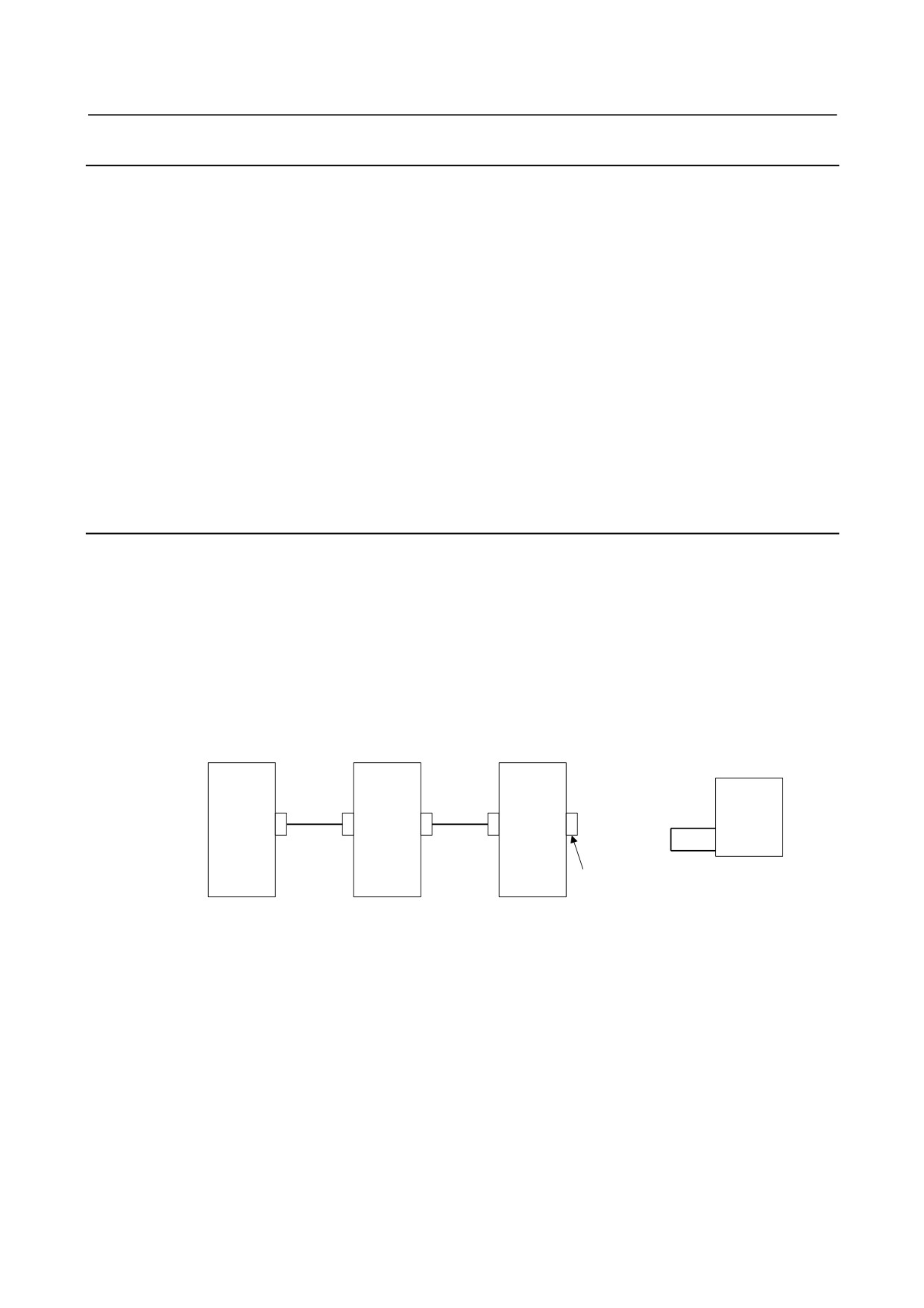
(2) About CNC alarms 756 and 766 (abnormal axis number)
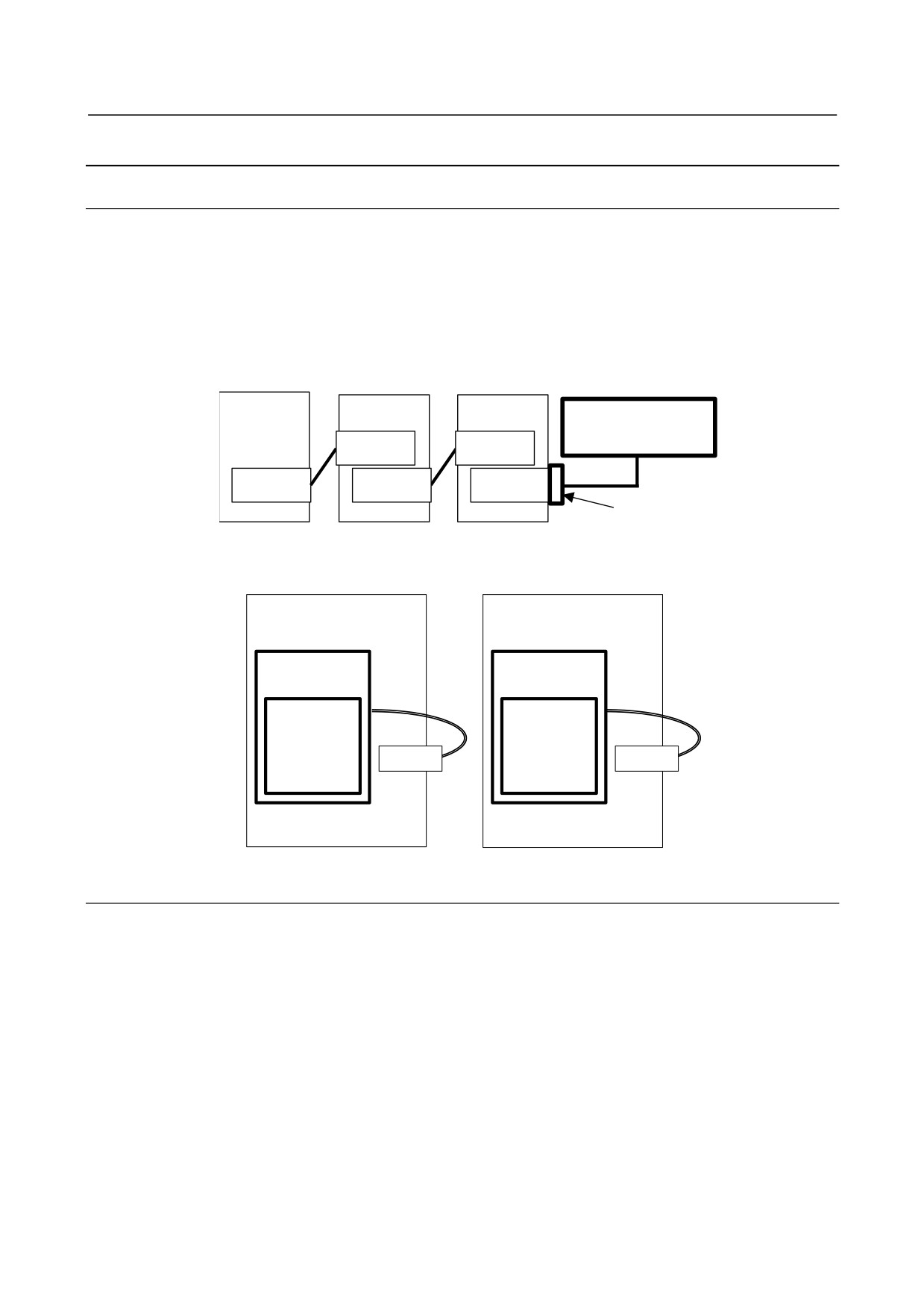
These alarms can be issued only when the Dual Check Safety function is in use. If this alarm is issued,
check that K76 shown below is attached to the JA7A connector of the second spindle. K76 is
unnecessary if only the first spindle is used. If the wiring is normal, replace the Spindle Amplifier
control printed-circuit board.
Details of K76
CNC
SP
SP
(First spindle)
(Second
K76
spindle)
JA41 JA7B
JA7A
JA7B
JA7A
X2NDSP
(15)
0V
(13)
K76
20-pin half-pitch
connector
- 104 -
3.TROUBLESHOOTING AND
B-65285EN/04
TROUBLESHOOTING
ACTION
3.5
αCi SERIES SPINDLE AMPLIFIER MODULE
This section explains those alarm codes for the αCi series which require troubleshooting sequences that are
different from those for the αi series even when the alarm numbers are the same.
For explanations about the alarm codes not stated herein, see the descriptions about the corresponding
number given in Section 2.4, "Spindle Amplifier."
3.5.1
Alarm Code 12
An excessive motor current was detected.
An excessively large current flowed into the DC link of the main circuit.
For SPMC-2.2i to -15i
An overload, overcurrent, or a low control power supply voltage was detected in the power module (IPM)
of the main circuit.
(1)
If this alarm is issued on SPMC-2.2i to -15i
Check alarm code 09 as well.
(2)
If this alarm is issued immediately after a spindle rotation command is specified
(a) The motor power lead is faulty.
Check for a short circuit between motor power leads and short-circuit to ground, and replace the
power lead as required.
(b) The insulation of the motor winding is defective.
If the motor is short-circuited to ground, replace the motor.
(c) The parameters specific to the motor are not set correctly.
Refer to "FANUC AC SPINDLE MOTOR αi series Parameter Manual (B-65280EN)."
(d) The SPMC is faulty.
A power element (IGBT, IPM) may be destroyed. Replace the SPMC.
(3)
If this alarm is issued during spindle rotation
(a) Belt slippage
It is likely that there may be belt slippage between the spindle and motor. Clean the pulleys and
adjust the belt tension.
(b) The parameters specific to the motor are not set correctly.
Referring to "FANUC AC SPINDLE MOTOR αi series Parameter Manual (B-65280EN)," check
the parameters specific to the motor.
(c) The SPMC is faulty.
A power element (IGBT, IPM) may be destroyed. Replace the SPMC.
If the amplifier setting condition is not satisfied, or cooling is insufficient because the heat sink is
dirty, the power elements may be destroyed.
When the heat sink on the back of the amplifier is too dirty, clean the heat sink, for example, by
blowing air. Consider the use of a structure that prevents the heat sink from being directly
exposed to coolant.
For the installation condition, refer to "FANUC SERVO AMPLIFIER αi series Descriptions
(B-65282EN)."
- 105 -
3.TROUBLESHOOTING AND
ACTION
TROUBLESHOOTING
B-65285EN/04
3.5.2
Alarm Code 35
There is a large difference between the motor speed calculated from the position coder and the motor speed
estimated with the spindle software.
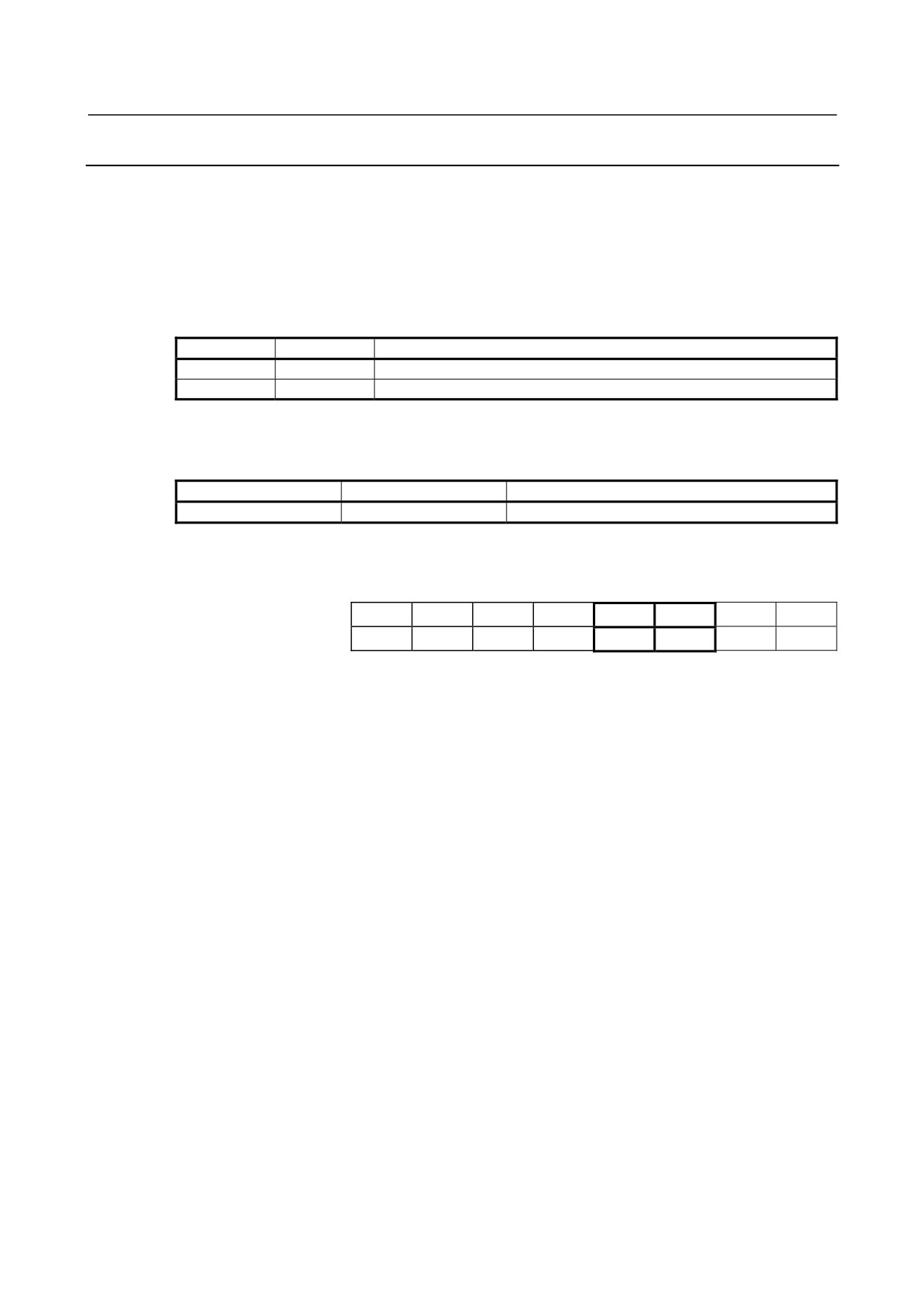
(1) If an alarm is issued when a rotation command is entered
(a) Error in the position coder setting parameter
Correctly specify the bits representing the relationships between the direction of position coder
rotation and that of spindle rotation and between the direction of spindle rotation and that of
motor rotation.
FS15i
FS16i
Description
3000#0
4000#0
Spindle and spindle motor rotation directions
3001#4
4001#4
Spindle sensor (position coder) mounting direction
(b) Invalid gear ratio parameter setting
Check to see if an incorrect gear ratio has been specified.
This value is used to convert the position coder speed to the motor speed. Be sure to specify the
correct value.
FS15i
FS16i
Description
3056 to 3059
4056 to 4059
Spindle-motor gear ratio data
(c) Clutch/gear signal error
Make sure that the entered clutch/gear signals (CTH1A, CTH2A) are correct with respect to the
actually selected gear.
FS15i
FS16i
#7
#6
#5
#4
#3
#2
#1
#0
First spindle
G227 G070
CTH1A
CTH2A
Second spindle
G235 G074
CTH1B
CTH2B
(d) Belt slippage between the spindle and spindle motor
Make adjustments so that no belt slippage will occur between the spindle and spindle motor.
(2) If an alarm is issued during a cutting operation
An overload has occurred to decrease the motor speed.
Review the cutting condition.
- 106 -
4.REPLACING AMPLIFIER
B-65285EN/04
TROUBLESHOOTING
COMPONENTS
4 REPLACING AMPLIFIER COMPONENTS
This chapter describes how to replace a fan motor, absolute Pulsecoder battery, fuses, and printed-circuit
board.
WARNING
Because the Servo Amplifier uses a large-capacitance electrolytic capacitor
internally, the Servo Amplifier remains charged for a while even after the power is
turned off. Before touching the Servo Amplifier for maintenance or other purposes,
ensure your safety by measuring the residual voltage in the DC link with a tester
and confirming that the charge indication LED (red) is off.
4.1
REPLACEMENT OF A FAN MOTOR
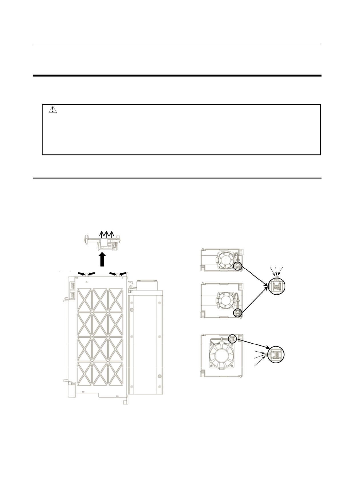
(1) Fan motor for internal cooling
Replace the internal fan motor, according to the procedure shown in the figure below.
When replacing the fan motor, be careful about the direction of the fan motor (air blow direction), the
direction of the connector, etc.
Air blow direction
Fan unit
(2) Remove the fan
(1) Hold the two tabs
and get the fan unit
unit by pulling it
White Black Red
off the latch.
upward.
Fan unit (60-mm-wide)
Tab
Tab
Be careful about the
connector key direction.
Fan unit (90-mm-wide)
Red
Black
White
Be careful about the
connector key direction.
Fan unit (150-mm-wide)
* Be careful about the fan motor and connector directions.
- 107 -
4.REPLACING AMPLIFIER
COMPONENTS
TROUBLESHOOTING
B-65285EN/04
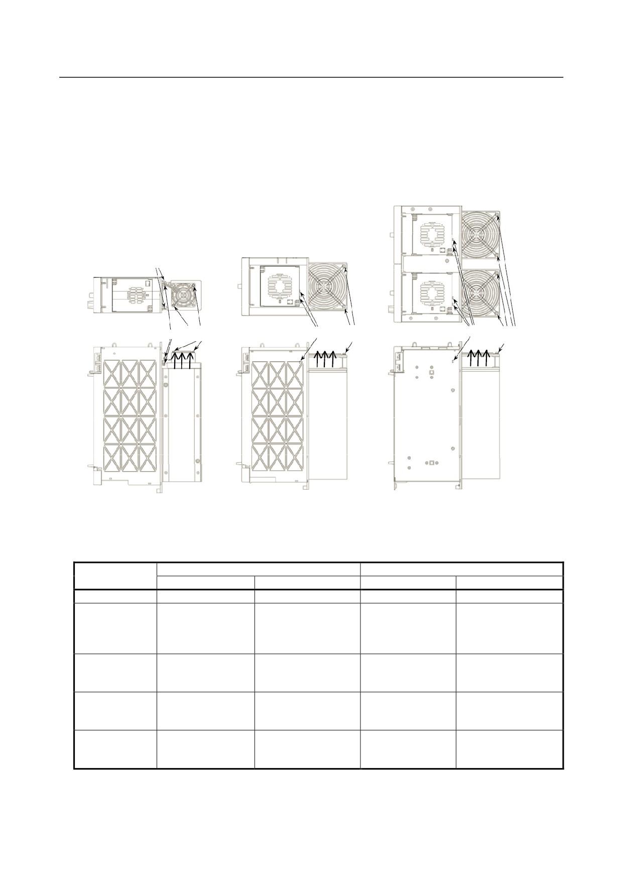
(2) Fan motor for cooling the external radiator
<1> Remove the two sheet metal mounting screws (for the 60-mm-wide model only), and detach the
fan motor from the unit together with the sheet metal.
<2> Remove the fan motor mounting screws (two for one fan motor and four for two fan motors).
<3> Remove the connector mounting screws (two and four for the 300-mm-wide model).
When replacing the fan motor, be careful about the direction of the fan motor (air blow direction), the
direction of the connector, etc.
Sheet metal mounting screws
Fan motor
Fan motor
Fan motor
Connector mounting screw
Connector mounting screw
Connector mounting screw
mounting screw
mounting screw
mounting screw
Air blow
Air blow
Air blow
direction
direction
direction
60 mm wide/90 mm wide
150 mm wide
300 mm wide
Specification number of fan unit
- Power Supply
Internal cooling fan
Radiator cooling fan
Model name
Fan unit (*1)
Fan motor
Fan unit (*1)
Fan motor
αiPS 5.5
-
A90L-0001-0441/39
-
-
αiPS 11
αiPS 15
-
A90L-0001-0441/39
A06B-6110-C603
A90L-0001-0508
αiPS 11HV
αiPS 18HV
αiPS 26
αiPS 30
-
A90L-0001-0441/39
(A06B-6110-C604)
A90L-0001-0509
αiPS 37
αiPS 30HV
A06B-6110-C607
A90L-0001-0441/39
αiPS 45HV
(A06B-6110-C604)
A90L-0001-0509
A90L-0001-0511(*2)
αiPS 60HV
αiPS 55
A06B-6110-C607
A90L-0001-0441/39
(A06B-6110-C604)
A90L-0001-0509
αiPS 75HV
Two are used.
A90L-0001-0511(*2)
Two are used.
Two are used.
αiPS 100HV
- 108 -
4.REPLACING AMPLIFIER
B-65285EN/04
TROUBLESHOOTING
COMPONENTS
- Servo Amplifier
(1) 200 V input with one axis
Internal cooling fan
Radiator cooling fan
Model name
Fan unit (*1)
Fan motor
Fan unit (*1)
Fan motor
αiSV 4
A06B-6110-C605
A90L-0001-0510
αiSV 20
A06B-6110-C605
A90L-0001-0510
-
-
αiSV 40
A06B-6110-C605
A90L-0001-0510
-
-
αiSV 80
A06B-6110-C605
A90L-0001-0510
-
-
αiSV 160
A06B-6110-C605
A90L-0001-0510
A06B-6110-C602
A90L-0001-0507/B
αiSV 360
A06B-6110-C607
A90L-0001-0511
(A06B-6110-C604)
A90L-0001-0509
αiSV 20L
A06B-6110-C605
A90L-0001-0510
αiSV 40L
A06B-6110-C605
A90L-0001-0510
αiSV 80L
A06B-6110-C605
A90L-0001-0510
A06B-6110-C602
A90L-0001-0507/B
αiSV 160L
A06B-6110-C606
A90L-0001-0510
A06B-6110-C603
A90L-0001-0508
(2) 200 V input with two axes
Internal cooling fan
Radiator cooling fan
Model name
Fan unit (*1)
Fan motor
Fan unit (*1)
Fan motor
αiSV 4/4
A06B-6110-C605
A90L-0001-0510
-
-
αiSV 4/20
A06B-6110-C605
A90L-0001-0510
αiSV 20/20
A06B-6110-C605
A90L-0001-0510
-
-
αiSV 20/40
A06B-6110-C605
A90L-0001-0510
-
-
αiSV 40/40
A06B-6110-C605
A90L-0001-0510
A06B-6110-C601
A90L-0001-0507/A
αiSV 40/80
A06B-6110-C605
A90L-0001-0510
A06B-6110-C601
A90L-0001-0507/A
αiSV 80/80
A06B-6110-C605
A90L-0001-0510
A06B-6110-C601
A90L-0001-0507/A
αiSV 80/160
A06B-6110-C606
A90L-0001-0510
A06B-6110-C603
A90L-0001-0508
αiSV 160/160
A06B-6110-C606
A90L-0001-0510
A06B-6110-C603
A90L-0001-0508
αiSV 20/20L
A06B-6110-C605
A90L-0001-0510
αiSV 20/40L
A06B-6110-C605
A90L-0001-0510
A06B-6110-C601
A90L-0001-0507/A
αiSV 40/40L
A06B-6110-C605
A90L-0001-0510
A06B-6110-C601
A90L-0001-0507/A
αiSV 40/80L
A06B-6110-C606
A90L-0001-0510
A06B-6110-C603
A90L-0001-0508
αiSV 80/80L
A06B-6110-C606
A90L-0001-0510
A06B-6110-C603
A90L-0001-0508
(*1) A fan unit is a set of a fan motor and a cover for mounting it. A fan motor can be replaced separately
from the fan unit. The fan unit A06B-6110-C604, enclosed in parentheses, cannot be dismounted from
the outside. So replace only the fan motor, which can be dismounted from the outside. (See Section
III-1.3, "HOW TO REPLACE THE FAN MOTOR.")
(*2) For A06B-6110-C607
(3) 200 V input with three axes
Internal cooling fan
Radiator cooling fan
Model name
Fan unit (*1)
Fan motor
Fan unit
Fan motor
αiSV 4/4/4
A06B-6110-C605
A90L-0001-0510
-
-
αiSV 20/20/20
A06B-6110-C605
A90L-0001-0510
-
A90L-0001-0385/T(*2)
αiSV 20/20/40
A06B-6110-C605
A90L-0001-0510
-
-
- 109 -
4.REPLACING AMPLIFIER
COMPONENTS
TROUBLESHOOTING
B-65285EN/04
(4) 400 V input with one axis
Internal cooling fan
Radiator cooling fan
Model name
Fan unit (*1)
Fan motor
Fan unit (*1)
Fan motor
αiSV 10HV
A06B-6110-C605
A90L-0001-0510
-
-
αiSV 20HV
A06B-6110-C605
A90L-0001-0510
-
-
αiSV 40HV
A06B-6110-C605
A90L-0001-0510
-
-
αiSV 80HV
A06B-6110-C605
A90L-0001-0510
A06B-6110-C602
A90L-0001-0507/B
αiSV 180HV
A06B-6110-C607
A90L-0001-0511
(A06B-6110-C604)
A90L-0001-0509
A06B-6110-C607
A90L-0001-0511
(A06B-6110-C604)
A90L-0001-0509
αiSV 360HV
Two are used.
Two are used.
Two are used.
Two are used.
A06B-6110-C607
A90L-0001-0511
(A06B-6110-C604)
A90L-0001-0509
αiSV 540HV
Two are used.
Two are used.
Two are used.
Two are used.
αiSV 10HVL
A06B-6110-C605
A90L-0001-0510
αiSV 20HVL
A06B-6110-C605
A90L-0001-0510
αiSV 40HVL
A06B-6110-C605
A90L-0001-0510
A06B-6110-C602
A90L-0001-0507/B
αiSV 80HVL
A06B-6110-C606
A90L-0001-0510
A06B-6110-C603
A90L-0001-0508
(5) 400 V input with two axes
Internal cooling fan
Radiator cooling fan
Model name
Fan unit (*1)
Fan motor
Fan unit (*1)
Fan motor
αiSV 10/10HV
A06B-6110-C605
A90L-0001-0510
-
-
αiSV 20/20HV
A06B-6110-C605
A90L-0001-0510
-
-
αiSV 20/40HV
A06B-6110-C606
A90L-0001-0510
A06B-6110-C603
A90L-0001-0508
αiSV 40/40HV
A06B-6110-C606
A90L-0001-0510
A06B-6110-C603
A90L-0001-0508
αiSV 40/80HV
A06B-6110-C606
A90L-0001-0510
A06B-6110-C603
A90L-0001-0508
αiSV 80/80HV
A06B-6110-C606
A90L-0001-0510
A06B-6110-C603
A90L-0001-0508
αiSV 10/10HVL
A06B-6110-C605
A90L-0001-0510
αiSV 20/20HVL
A06B-6110-C605
A90L-0001-0510
A06B-6110-C601
A90L-0001-0507/A
αiSV 20/40HVL
A06B-6110-C606
A90L-0001-0510
A06B-6110-C603
A90L-0001-0508
αiSV 40/40HVL
A06B-6110-C606
A90L-0001-0510
A06B-6110-C603
A90L-0001-0508
(*1) A fan unit is a set of a fan motor and a cover for mounting it. A fan motor can be replaced separately
from the fan unit. The fan unit A06B-6110-C604, enclosed in parentheses, cannot be dismounted from
the outside. So replace only the fan motor, which can be dismounted from the outside.
(*2) The αiSV 20/20/20 has, within its housing, a fan motor for cooling the heat sink fins on the power
transistor.
- 110 -

4.REPLACING AMPLIFIER
B-65285EN/04
TROUBLESHOOTING
COMPONENTS
- Spindle Amplifier
Internal cooling fan
Radiator cooling fan
Model name
Fan unit (*1)
Fan motor
Fan unit (*1)
Fan motor
αiSP 2.2
A06B-6110-C605
A90L-0001-0510
-
-
αiSP 5.5
A06B-6110-C605
A90L-0001-0510
A06B-6110-C601
A90L-0001-0507/A
αiSP 5.5HV
A06B-6110-C605
A90L-0001-0510
A06B-6110-C602
A90L-0001-0507/B
αiSP 11
αiSP 15
A06B-6110-C606
A90L-0001-0510
A06B-6110-C603
A90L-0001-0508
αiSP 11HV
αiSP 15HV
αiSP 22
αiSP 26
αiSP 30
A06B-6110-C607
A90L-0001-0511
(A06B-6110-C604)
A90L-0001-0509
αiSP 37
αiSP 30HV
αiSP 45HV
αiSP 45
αiSP 55
A06B-6110-C607
A90L-0001-0511
(A06B-6110-C604)
A90L-0001-0509
αiSP 75HV
Two are used.
Two are used.
Two are used.
Two are used.
αiSP 100HV
(*1) A fan unit is a set of a fan motor and a cover for mounting it. A fan motor can be replaced separately
from the fan unit. The fan unit A06B-6110-C604, enclosed in parentheses, cannot be dismounted from
the outside. So replace only the fan motor, which can be dismounted from the outside.
- 111 -

4.REPLACING AMPLIFIER
COMPONENTS
TROUBLESHOOTING
B-65285EN/04
4.2
REPLACING BATTERY FOR ABSOLUTE PULSECODERS
4.2.1
Overview
• When the voltage of the batteries for absolute Pulsecoders becomes low, alarm 307 or 306 occurs, with
the following indication in the CNC state display at the bottom of the CNC screen.
Alarm 307 (alarm indicating the voltage of the battery becomes low) :
The indication "APC" blinks in reversed display.
Alarm 306 (battery zero alarm) :
The indication "ALM" blinks in reversed display.
• When alarm 307 (alarm indicating the voltage of the battery becomes low) occurs, replace the battery
as soon as possible. In general, the battery should be replaced within one or two weeks, however, this
depends on the number of Pulsecoders used.
• When alarm 306 (battery zero alarm) occurs, Pulsecoders are reset to the initial state, in which absolute
positions are not held. Alarm 300 (reference position return request alarm) also occurs, indicating that
reference position return is required.
• In general, replace the batteries periodically within the service life listed below.
-
A06B-6050-K061 or D-size alkaline dry cells (LR20) : Two years
(for each six-axis
configuration)
-
A06B-6073-K001 : Two years (for each three-axis configuration)
-
A06B-6114-K504 : One year (for each three-axis configuration)
NOTE
The above values indicate the estimated service life of batteries used with FANUC
absolute Pulsecoders. The actual battery service life depends on the machine
configuration based on, for example, detector types. For details, contact the
machine tool builder.
4.2.2
Replacing Batteries
To prevent absolute position information in absolute Pulsecoders from being lost, turn on the machine
power before replacing the battery. The replacement procedure is described below.
<1> Ensure that the power to the servo amplifier is turned on.
<2> Ensure that the machine is in the emergency stop state (the motor is inactive).
<3> Ensure that the DC link charge LED of the servo amplifier is off.
<4> Detach the old batteries and attach new ones.
The replacement of the batteries in a separate battery case and the replacement of the battery built into the
servo amplifier are described below in detail.
- 112 -
4.REPLACING AMPLIFIER
B-65285EN/04
TROUBLESHOOTING
COMPONENTS
WARNING
• The absolute Pulsecoder of each of the αi/αi S series servo motors and the βi S
series servo motors (βi S0.4 to βi S22) has a built-in backup capacitor. Therefore,
even when the power to the servo amplifier is off and the batteries are replaced,
reference position return is not required if the replacement completes within less
than 10 minutes. Turn the power on and replace the batteries if the replacement
will take 10 minutes or more.
• To prevent electric shock, be careful not to touch metal parts in the power
magnetics cabinet when replacing the batteries.
• Because the servo amplifier uses a large-capacitance electrolytic capacitor
internally, the servo amplifier remains charged for a while even after the power is
turned off. Before touching the servo amplifier for maintenance or other purposes,
ensure your safety by measuring the residual voltage in the DC link with a tester
and confirming that the charge indication LED (red) is off.
• Be sure to replace the batteries with specified ones. Pay attention to the battery
polarity. If a wrong type of battery is used or a battery is installed with incorrect
polarity, the battery may overheat, blow out, or catch fire, or the absolute position
information in the absolute Pulsecoders may be lost.
• Ensure that the battery connector is inserted in the correct position.
4.2.3
Replacing the Batteries in a Separate Battery Case
Use the following procedure to replace the batteries in the battery case.
<1> Loosen the screws on the battery case and detach the cover.
<2> Replace the batteries in the case (pay attention to the polarity).
<3> Attach the cover to the battery case.
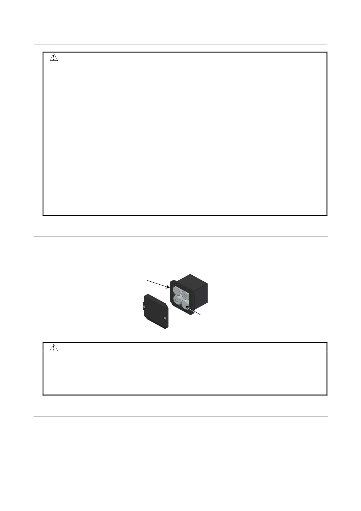
Battery case (with a cover)
A06B-6050-K060
Batteries
Four A06B-6050-K061 batteries or
D-size alkaline dry cells
CAUTION
• Four D-size alkaline dry cells (LR20) that are commercially available can be used
as batteries. A set of four A06B-6050-K061 batteries is optionally available from
FANUC.
• Replace all the four batteries with new ones. If old and new batteries are mixed,
the absolute position information in the absolute Pulsecoders may be lost.
4.2.4
Replacing the Battery Built into the Servo Amplifier
Use the following procedure to replace the special lithium battery.
<1> Detach the battery case.
<2> Replace the special lithium battery.
<3> Attach the battery case.
- 113 -
4.REPLACING AMPLIFIER
COMPONENTS
TROUBLESHOOTING
B-65285EN/04
CAUTION
•
Purchase the battery from FANUC because it is not commercially available. It is
therefore recommended that you have a backup battery.
•
When the built-in battery is used, do not connect BATL (B3) of connector
CXA2A/CXA2B. Also, do not connect two or more batteries to the same BATL (B3)
line. These connections are dangerous because battery output voltages may be
short-circuited, causing the batteries to overheat.
•
Install the battery in the servo amplifier in a direction that allows slack in the cable.
If the battery cable is under tension, a bad connection may occur.
•
If the +6 V pin and 0 V pin are short-circuited, the battery may overheat, blow out,
or catch fire, or the absolute position information in the absolute Pulsecoders may
be lost.
•
When inserting the connector, align it to the connector pins.
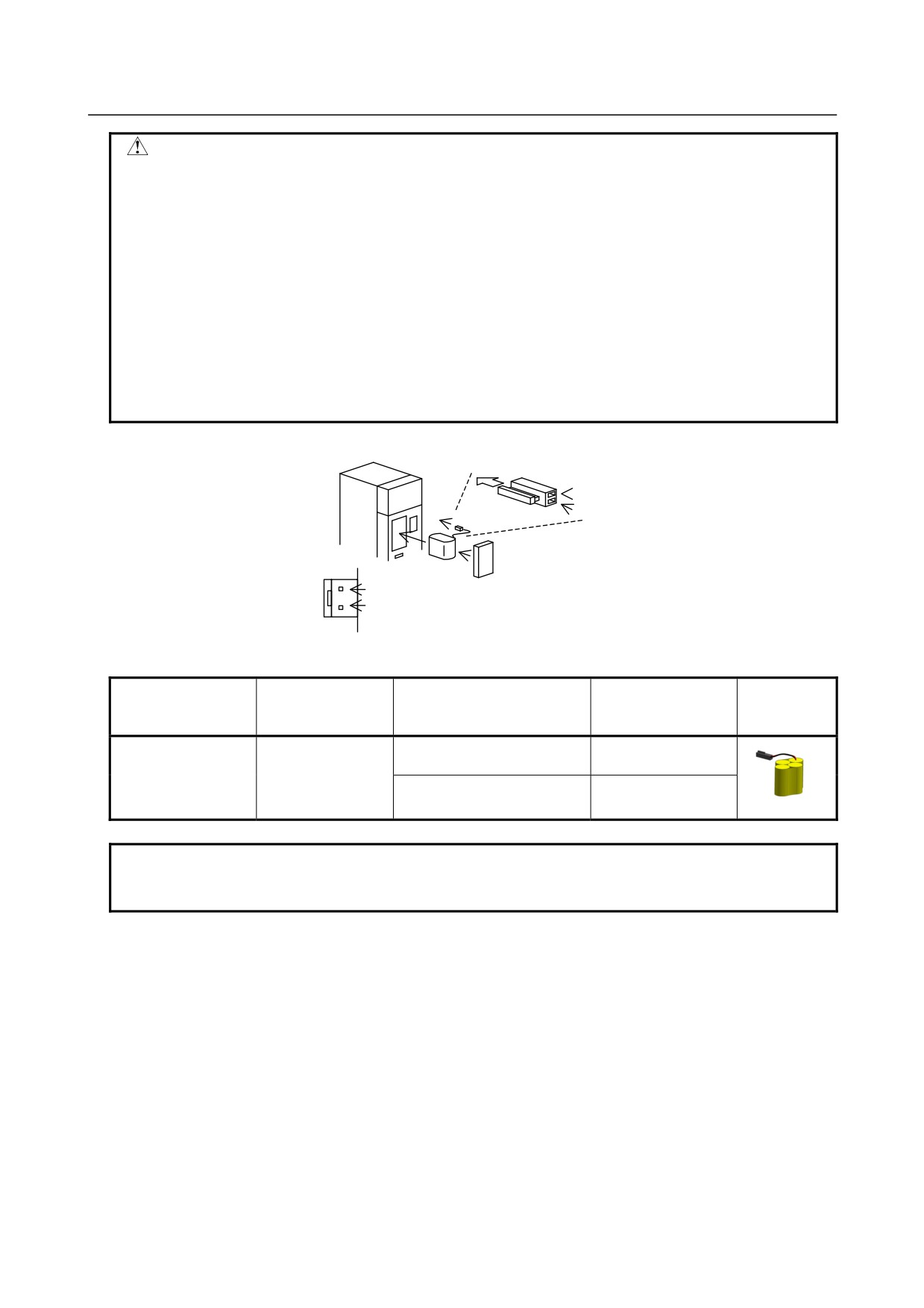
Insertion direction
Red: +6 V
Connector
Black: 0 V
CX5X
Battery
+6 V
Battery case
0 V
[Battery sets and outlines]
Battery case
Battery ordering
Manufacturer
Applicable servo amplifier
ordering drawing
Outline
drawing number
model number
number
αi series
60/90 mm width
A06B-6114-K505
A06B-6114-K504
BR-2/3AGCT4A
(Note)
(Panasonic)
αi series
150/300 mm width
A06B-6114-K506
NOTE
When using an old-type battery BR-CCF2TH, order a battery case applicable for
battery A06B-6114-K504.
Used batteries
Old batteries should be disposed as "INDUSTRIAL WASTES" according to the regulations of the country
or autonomy where your machine has been installed.
- 114 -
4.REPLACING AMPLIFIER
B-65285EN/04
TROUBLESHOOTING
COMPONENTS
4.2.5
Notes on Replacing a Battery (Supplementary Explanation)
4.2.5.1 Battery connection modes
For absolute Pulsecoders, there are two types of battery connection modes: "Connecting batteries in a
separate battery case" and "connecting batteries built into the Servo Amplifier." For details, refer to
Subsection 9.3.2.10, "Connecting the battery (for the absolute Pulsecoder)," in the FANUC SERVO
AMPLIFIER αi series Descriptions (B-63282EN).
[Batteries in a separate battery case]
Battery case
A06B-6050-K060
αiPS
αiSV
αiSV
Battery
A06B-6050-K061
CXA2B
CXA2B
CXA2A
CXA2A
CXA2A
Connector
A06B-6110-K211
[Batteries built into the Servo Amplifier]
αiSV
αiSV
Battery case
Battery case
Battery
Battery
CX5X
CX5X
4.2.5.2 Connecting the battery for the α series motor
The Pulsecoder for the α series servo motor is not incorporated with a backup capacitor as standard. To
keep the absolute position information in the absolute Pulsecoder, you need to keep the control power
turned on during battery replacement. Follow the procedure explained below.
[Replacing procedure for the battery]
1.
Make sure that the power to the Servo Amplifier is on (the 7-segment LED on the front of the SVM is
on).
2.
Make sure that the emergency stop button of the system has been pressed.
3.
Make sure that the motor is not activated.
4.
Make sure that the DC link charge LED of the SVM is off.
5.
Remove the old battery, and install a new battery.
6.
This completes the replacement. You can turn off the power to the system.
- 115 -
4.REPLACING AMPLIFIER
COMPONENTS
TROUBLESHOOTING
B-65285EN/04
WARNING
1 When replacing the battery, be careful not to touch bare metal parts in the panel.
In particular, be careful not to touch any high-voltage circuits due to the electric
shock hazard.
2 Before replacing the battery, check that the DC link charge confirmation LED on
the front of the servo amplifier is off. Neglecting this check creates an electric
shock hazard.
3 Install the battery with correct polarity. If the battery is installed with incorrect
polarity, it may overheat, blow out, or catch fire.
4 Avoid a short-circuit between the +6 V and 0 V lines of a battery or cable. A
short-circuit may lead to a hot battery, an explosion, or fire.
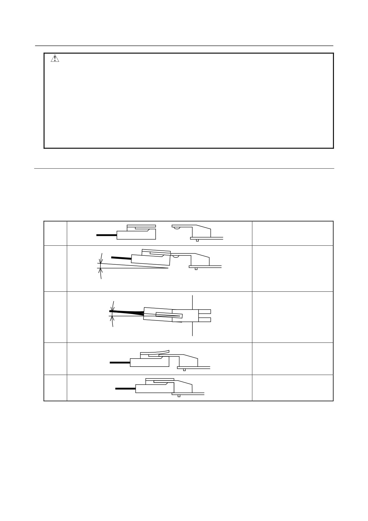
4.2.5.3 Notes on attaching connectors
If an excessive strain is applied to a connector when it is inserted or removed, a poor contact may result.
When inserting and removing the battery connector, therefore, be careful not to apply an excessive
wrenching force to it; just follow the instructions given in the following table.
(1) Attaching connectors
Check the attachment
<1>
position.
Plug the cable connector while
<2>
raising it slightly.
10 degrees or less
Here, the angle of the cable
<5>
connector to the horizontal
must be 5 degrees or less.
5 degrees or less
After passing the lock pin,
<3>
insert the connector straight.
The attachment of the
<4>
connector is completed.
- 116 -
4.REPLACING AMPLIFIER
B-65285EN/04
TROUBLESHOOTING
COMPONENTS
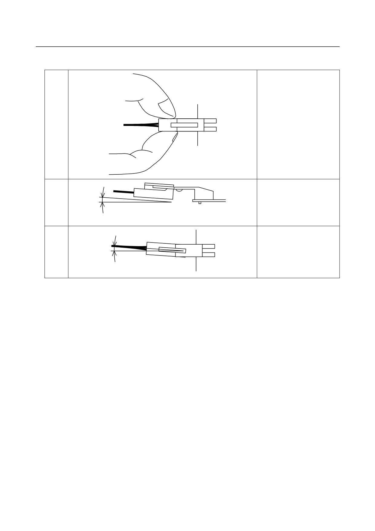
(2) Detaching the connector
<1>
Hold both the sides of the
cable insulator and the cable,
and pull them horizontally.
<2>
Pull out the cable side while
raising it slightly.
10 degrees or less
<3>
Here, the angle of the cable to
the horizontal must be 5
degrees or less.
5 degrees or less
- 117 -
4.REPLACING AMPLIFIER
COMPONENTS
TROUBLESHOOTING
B-65285EN/04
4.3
HOW TO REPLACE THE FUSES
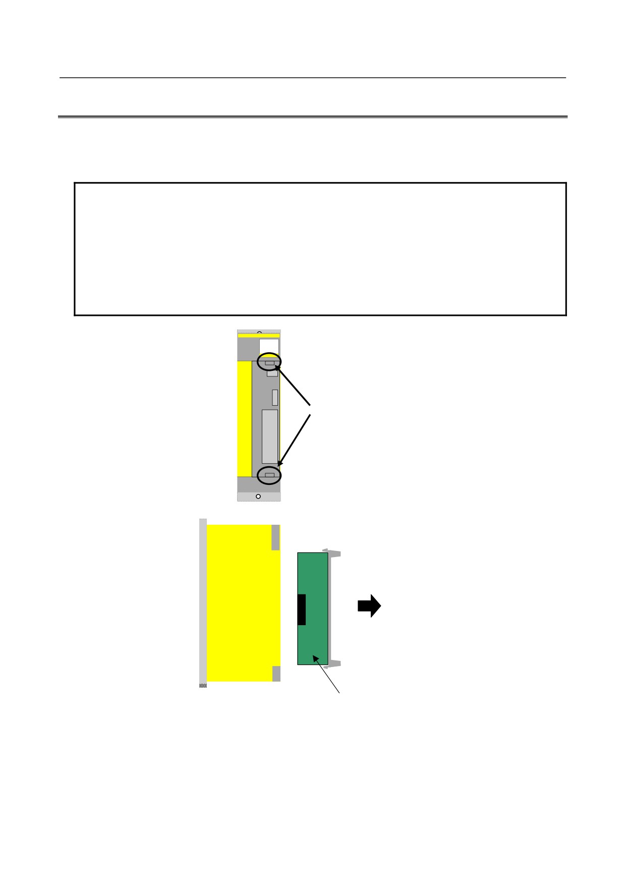
In the αi series, a printed-circuit board can be removed and inserted from the front of the servo amplifier.
The printed-circuit board removal/insertion procedure is common to the Power Supply, Servo Amplifier,
and Spindle Amplifier.
NOTE
1 If a fuse blows, it is likely that there is a short-circuit in the power supply for a
device (such as a sensor) connected to the Servo Amplifier.
After checking that all devices connected to the Servo Amplifier are normal,
replace the fuse.
If you do not remove the cause, it is very much likely that the fuse will blow again.
2 Do not use any fuse not supplied from FANUC.
3 Before replacing a fuse, check a marking on it with that on the printed-circuit
board. Be careful not to mount a fuse with an incorrect rating.
Hold the upper and
lower hooks.
Pull the printed-circuit
board toward you.
Printed circuit board
To insert the printed-circuit board, reverse the above procedure.
Ensure that the upper and lower hooks snap into the housing.
If the printed-circuit board is not inserted completely, the housing remains lifted. Pull out the printed-circuit
board and insert it again.
- 118 -
4.REPLACING AMPLIFIER
B-65285EN/04
TROUBLESHOOTING
COMPONENTS
4.3.1
Fuse Locations
4.3.1.1 Power Supply
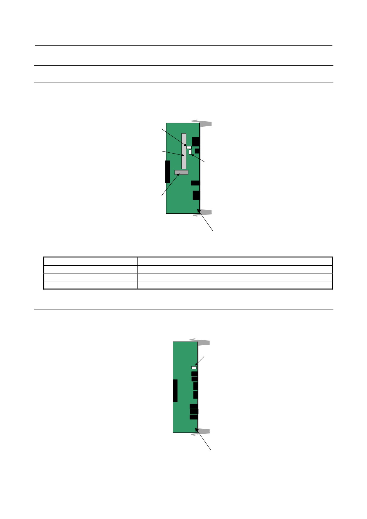
There are two different fuses on the Power Supply printed-circuit board. Be careful not to confuse their
ratings during replacement.
FU1 (5A)
(Rating indicated in red)
Cooling fin
FU2 (2A)
(Rating indicated in white)
Fan motor
Printed circuit board
Fuse specification
Symbol
Ordering number
FU1
A60L-0001-0359
FU2
A60L-0001-0176/2.0A
FU3
A60L-0001-0290/LM32C
4.3.1.2 Servo Amplifier
There is one fuse on the Servo Amplifier printed-circuit board.
FU1 (3.2A)
(Rating indicated in white)
Printed circuit board
- 119 -
4.REPLACING AMPLIFIER
COMPONENTS
TROUBLESHOOTING
B-65285EN/04
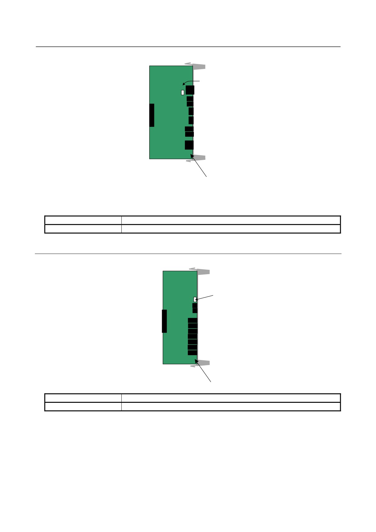
FU1 (3.2A)
(Rating indicated in white)
Printed circuit board
Fuse specification
Symbol
Ordering number
FU1
A60L-0001-0290/LM32C
4.3.1.3 Spindle Amplifier
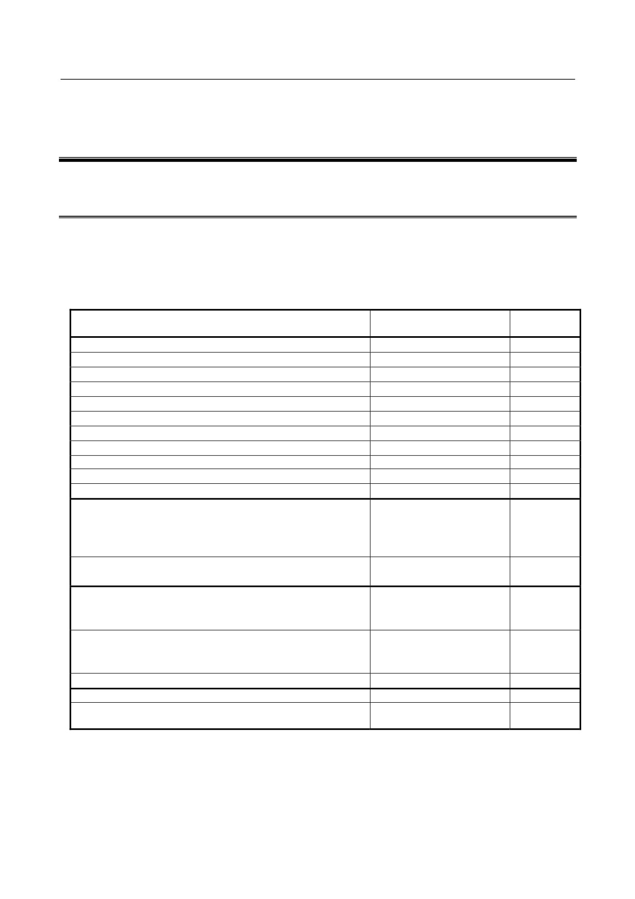
F1 (3.2A)
(Rating indicated in white)
Printed circuit board
Fuse specification
Symbol
Ordering number
F1
A60L-0001-0290/LM32C
- 120 -
III. MOTOR/DETECTOR/AMPLIFIER
PREVENTIVE MAINTENANCE
MOTOR/DETECTOR/AMPLIFIER
1.MOTOR/DETECTOR/AMPLIFIER
B-65285EN/04
PREVENTIVE MAINTENANCE
PREVENTIVE MAINTENANCE
This chapter describes preventive maintenance of motors, detectors, and amplifiers that is to be performed
by the customer the machine uses.
Contents
1
MOTOR/DETECTOR/AMPLIFIER PREVENTIVE MAINTENANCE ... 124
1.1
LIST OF MANUALS RELATED TO MOTORS AND AMPLIFIERS
124
1.2
PREVENTIVE MAINTENANCE OF MOTORS AND DETECTORS
125
1.2.1
Warnings, Cautions, and Notes on Preventive Maintenance of Motors and
Detectors
125
1.2.2
Preventive Maintenance of a Motor (Common to All Models)
127
1.2.2.1
Main inspection items
127
1.2.2.2
Periodic cleaning of a motor
130
1.2.2.3
Notes on motor cleaning
130
1.2.2.4
Notes on the cutting fluid (informational)
130
1.2.3
Routine Inspection of a Spindle Motor with a Through Hole
131
1.2.4
Preventive Maintenance of a Built-in Spindle Motor and Spindle Unit
131
1.2.4.1
Routine inspection of the FANUC-NSK spindle unit
132
1.2.4.2
Maintenance of the FANUC-NSK spindle unit
132
1.2.4.3
Test run of the FANUC-NSK spindle unit
133
1.2.4.4
Storage method of the FANUC-NSK spindle unit
133
1.2.5
Preventive Maintenance of a Linear Motor
133
1.2.5.1
Appearance inspection of the linear motor (magnet plate)
133
1.2.6
Maintenance of a Detector
134
1.2.6.1
Alarms for built-in detectors (αi and βi Pulsecoders) and troubleshooting
actions
134
1.2.6.2
Alarms for separate detectors and troubleshooting actions
135
1.2.6.3
Detailed troubleshooting methods
135
1.2.6.4
Maintenance of βiS motor Pulsecoders
137
1.3
PREVENTIVE MAINTENANCE OF SERVO AMPLIFIERS
138
1.3.1
Warnings, Cautions, and Notes on Operation of Servo Amplifiers
138
1.3.2
Preventive Maintenance of a Servo Amplifier
141
1.3.3
Maintenance of a Servo Amplifier
142
1.3.3.1
Display of the servo amplifier operation status
142
1.3.3.2
Replacement of a fan motor
144
1.4
REPLACING BATTERY FOR ABSOLUTE PULSECODERS
145
1.4.1
Overview
145
1.4.2
Replacing Batteries
146
1.4.3
Replacing the Batteries in a Separate Battery Case
146
1.4.4
Replacing the Battery Built into the Servo Amplifier
147
- 123 -
1.MOTOR/DETECTOR/AMPLIFIER MOTOR/DETECTOR/AMPLIFIER
PREVENTIVE MAINTENANCE PREVENTIVE MAINTENANCE
B-65285EN/04
1 MOTOR/DETECTOR/AMPLIFIER
PREVENTIVE MAINTENANCE
1.1
LIST OF MANUALS RELATED TO MOTORS AND
AMPLIFIERS
Details of individual motors and amplifiers are described in the manuals listed in the table below. Before
performing periodic inspection or any other maintenance work, consult with the machine tool builder and, if
necessary, obtain the latest version of the corresponding manual shown in the list. The information about
the specifications of each device, such as the weight and winding resistance value, is given in the relevant
"DESCRIPTIONS" manual.
Specification
Manual name
Type of manual
number
FANUC AC SERVO MOTOR αi series
DESCRIPTIONS
B-65262EN
FANUC AC SERVO MOTOR βis series
DESCRIPTIONS
B-65302EN
FANUC SYNCHROUNOUS BUILT-IN SERVO MOTOR DiS series
DESCRIPTIONS
B-65332EN
FANUC LINEAR MOTOR LiS series
DESCRIPTIONS
B-65382EN
FANUC AC SPINDLE MOTOR αi series
DESCRIPTIONS
B-65272EN
FANUC AC SPINDLE MOTOR βi series
DESCRIPTIONS
B-65312EN
FANUC BUILT-IN SPINDLE MOTOR BiI series
DESCRIPTIONS
B-65292EN
FANUC SYNCHROUNOUS BUILT-IN SPINDLE MOTOR BiS series
DESCRIPTIONS
B-65342EN
FANUC - NSK SPINDLE UNIT series
DESCRIPTIONS
B-65352EN
FANUC SERVO AMPLIFIER αi series
DESCRIPTIONS
B-65282EN
FANUC SERVO AMPLIFIER βi series
DESCRIPTIONS
B-65322EN
FANUC AC SERVO MOTOR αi series
FANUC AC SERVO MOTOR βi series
PARAMETER MANUAL
B-65270EN
FANUC LINEAR MOTOR LiS series
FANUC SYNCHRONOUS BUILT-IN SERVO MOTOR DiS series
FANUC AC SPINDLE MOTOR αi/βi series
PARAMETER MANUAL
B-65280EN
BUILT-IN SPINDLE MOTOR Bi series
FANUC AC SERVO MOTOR αis/αi series
AC SPINDLE MOTOR αi series
MAINTENANCE MANUAL
B-65285EN
SERVO AMPLIFIER αi series
FANUC AC SERVO MOTOR βis series
AC SPINDLE MOTOR βi series
MAINTENANCE MANUAL
B-65325EN
SERVO AMPLIFIER βi series
FANUC SERVO AMPLIFIER βi series
MAINTENANCE MANUAL
B-65395EN
FANUC SERVO GUIDE
OPERATOR’S MANUAL
B-65404EN
FANUC AC SERVO MOTOR αis/αi/βis series
SERVO TUNING
B-65264EN
PROCEDURE (BASIC)
- 124 -
MOTOR/DETECTOR/AMPLIFIER
1.MOTOR/DETECTOR/AMPLIFIER
B-65285EN/04
PREVENTIVE MAINTENANCE
PREVENTIVE MAINTENANCE
1.2
PREVENTIVE MAINTENANCE OF MOTORS AND
DETECTORS
1.2.1
Warnings, Cautions, and Notes on Preventive Maintenance of
Motors and Detectors
This subsection contains the safety precautions for motor and detector preventive maintenance, which are
classified into "warnings", "cautions", and "notes" according to their bearing on safety. Make sure that you
understand and comply with these precautions when carrying out the maintenance work.
WARNING
•
Make sure that you are safely dressed and have a safe working environment when
performing preventive maintenance for a motor.
-
Be dressed safely, e.g. by wearing gloves and safety shoes, to protect against injury due to an
edge or protrusion and electric shock.
-
Have the work done by more than one person, where possible, so that immediate action can be
taken if an accident occurs when handling a motor.
-
A motor is heavy. When moving it, use a crane or other appropriate equipment to protect against
injury. For information about the weight of the motor, refer to its DESCRIPTIONS manual
(shown earlier).
-
Clothes or fingers can be caught in a rotating motor or come into contact with a moving part of it.
Standing in the direction of motor rotation (direction of motion) can pose a risk of injury. Before
rotating a motor, check that there is no object that is thrown away by motor rotation.
•
Be careful about electric shock, fire, and other accidents.
-
Do not handle a motor with a wet hand.
-
To prevent electric shock, make sure that no conductive object, such as a terminal, is exposed
when the motor is powered on.
-
Before touching a motor or any surrounding part, check that the power is shut off and take
appropriate safety precautions.
-
High voltage remains across power line terminals of a motor even after the power is shut off (for
at least five minutes). Do not touch a motor in such a condition or connect it to other equipment.
-
A loose or disconnected terminal, short-circuited terminals, or a terminal connected to the ground
can cause overheating, spark, fire, or damage to the motor. Take appropriate precautions to
prevent these accidents.
-
When placed near any inflammable object or material, a motor can be ignited, catch fire, or
explode. Avoid placing it near such object or material.
•
Do not disassemble or modify a motor.
Motors such as linear motors, synchronous built-in servo motors, and synchronous built-in spindle
motors contain very strong magnets. If electronic medical apparatus comes near, these motors can
cause the apparatus to malfunction, potentially putting the user's life in danger. Also, disassembling or
modifying a motor can cause a failure, regardless of the type of motor. Do not disassemble or modify
a motor in any way not specified by FANUC.
- 125 -
1.MOTOR/DETECTOR/AMPLIFIER MOTOR/DETECTOR/AMPLIFIER
PREVENTIVE MAINTENANCE PREVENTIVE MAINTENANCE
B-65285EN/04
CAUTION
• Ensure that the specified cooling conditions are met.
If the specified cooling conditions are not met (the motor is insufficiently or excessively cooled), the
motor can fail. Problems that can cause a motor failure, such as liquid piping clog, leakage, and fan
motor trouble, should be eliminated through periodic inspection. Do not drive the motor when the
cooling system is in an abnormal condition.
• Do not change the system configuration.
Do not change the configuration of the system when it is running normally. Doing so can cause an
accident or failure. If you disconnect a cable for maintenance or some other purpose, take an
appropriate measure, such as putting a mark on it, to ensure you can restore the original state.
• Use the tapped holes of a motor only to move the motor.
Do not use the tapped holes of a motor to lift or move any other object along with the motor. Doing so
can damage the motor. Depending on the type of motor, the place and direction in which the motor can
be lifted may be predetermined. For details, refer to the DESCRIPTIONS manual of the motor (shown
earlier).
• Do not touch a motor when it is running or immediately after it stops.
A motor may get hot when it is running. Do not touch the motor before it gets cool enough. Otherwise,
you may get burned.
NOTE
• Do not remove a nameplate from a motor.
The nameplate is used to identify the motor during maintenance work. If a nameplate comes off, be
careful not to lose it.
• Do not step or sit on a motor, and avoid applying shock to a motor.
Any of these acts can deform or break the motor or affect its component, crippling the normal motor
operation. Do not put a motor on top of another motor.
• Comply with the specified conditions when conducting an electric test (winding
resistance test, insulation resistance test, etc.) for a motor or other device or
supplying power.
-
Conduct an electric test according to the specified method. Conducting such a test by any method
that is not specified can damage the motor.
-
Do not conduct a dielectric strength test or insulation test for a Pulsecoder or other detector, or do
not apply a commercial power source voltage. Doing so can destroy the internal elements.
• Perform preventive maintenance
(inspection of the external appearance,
measurement of winding resistance, insulation resistance, etc.) and cleaning on a
regular basis.
To use a motor safely throughout its entire service life, perform preventive maintenance and cleaning
on a regular basis. Be careful, however, because excessively severe inspection (dielectric strength test,
etc.) can damage its windings. For information about winding resistance values, refer to the
DESCRIPTIONS manual of the motor (its specification number is shown in this manual). Information
about insulation resistance is given later in this manual.
- 126 -

MOTOR/DETECTOR/AMPLIFIER
1.MOTOR/DETECTOR/AMPLIFIER
B-65285EN/04
PREVENTIVE MAINTENANCE
PREVENTIVE MAINTENANCE
NOTE
• This manual is focused on the preventive maintenance work to be performed for a
single FANUC motor or detector alone. The information contained herein may not
apply depending on the type or configuration of the machine. When reading this
manual, refer to the manual of the machine as well. If you have any questions or
doubts, do not act on your own; please contact the machine tool builder or
FANUC.
• For detailed information about a motor, see the manual list shown earlier and, if
necessary, obtain the latest version of the corresponding manual.
1.2.2
Preventive Maintenance of a Motor (Common to All Models)
This subsection describes the common preventive maintenance items to be handled regardless of the model
of the motor. For the items specific to a particular motor model, see one of the subsequent subsections that
pertains to that particular motor model.
CAUTION
• The preventive maintenance method differs from machine to machine in many
respects. Depending on the machine in use, it may be difficult for the user to
perform periodic inspection or cleaning. If you are not sure about anything as to
preventive maintenance, consult with the machine tool builder and ensure that you
can perform periodic inspection and cleaning.
• The machine should be used within the scope of specification defined by the
machine tool builder. Using the machine in any way that is outside the specified
scope can reduce the motor's service life or cause a failure.
1.2.2.1 Main inspection items
The following table summarizes the main inspection items for a motor. If any of these items is found to be
abnormal, stop the use of the machine immediately and fix the abnormal part by repairing or replacing
it. At the same time, identify and remove the cause and take a measure to prevent its recurrence. If it is
difficult to take a preventive measure or to prevent its recurrence, consult with the machine tool builder or
FANUC.
Appearance of
Crack or
-
Check the motor for any scar, crack, deformation, bulge, etc.
the motor
deformation
-
If the interior of the motor is visible or there is interference with a
peripheral component, it is imperative to replace the motor or the
peripheral component.
-
A light peel-off or scar of the surface may be repairable; consult with
FANUC.
Wet or dirty part
-
If you find any wet or dirty part, clean it immediately.
-
A preventive measure is needed if the part in question remains wet
continually due to cutting fluid or dew condensation.
Operating
Temperature,
-
Comply with the operating conditions of the machine. For details of the
conditions
humidity, etc.
operating conditions of a specific motor, refer to the corresponding
DESCRIPTIONS manual. Generally, the ambient temperature should be
0°C to 40°C (or 30°C for a spindle unit) and dew condensation is not
allowed. In a place subject to severe vibration, the components of the
motor may be broken.
- 127 -

1.MOTOR/DETECTOR/AMPLIFIER MOTOR/DETECTOR/AMPLIFIER
PREVENTIVE MAINTENANCE
PREVENTIVE MAINTENANCE
B-65285EN/04
Connection
Cable
-
Check for any cable sheath damage, exposed conductor, damaged
state
conduit or cable bearing, abnormal bending, loose terminal, etc.
-
If there is any trace of fluid flowing, the fluid may have entered the inside
of the motor or connector. It is necessary to make a check and take a
measure to prevent recurrence.
Connector/terminal
-
Check for any cracked, exposed, loose, or removed terminal or
connector, etc.
-
Fluid causes a failure; be sure to remove fluid.
-
A scarred or damaged connector or terminal needs to be replaced. In the
case of a resin molded motor, such as a linear motor, the motor needs to
be replaced.
Operation of
Noise/vibration
-
Check for any abnormal noise or vibration not only when the motor is
the motor
running (the spindle is rotating) but also when it is stopped.
-
Abnormal noise heard when the motor is rotating indicates an
abnormality of the bearing or a failure inside the motor.
-
If abnormal noise is generated from the connection section of a Spindle
Amplifier, check the following items:
Belt connection: Check whether the belt tension is appropriate.
Gear connection: Check whether an appropriate value is set for the gear
backlash.
Coupling connection: Check whether the coupling is free from
deformation, crack, and looseness.
Movement
-
Check that the motor operates normally and smoothly.
-
If the circuit breaker trips at the same time the motor starts to operate, it
indicates abnormal motor windings.
Heat
Check whether the motor does not overheat during the normal operation
cycle.
Note: While the motor is running or immediately after it is stopped, the motor
surface may become very hot. Instead of touching the motor directly by hand,
use a thermolabel, surface thermometer, etc.
Electric
Winding resistance
If the resistance value exceeds the specified range, the motor needs to be
characteristics
replaced.
of the motor
Note: When conducting winding resistance measurement, disconnect the
motor from the amplifier and measure the resistance at the power line or
connector closest to the motor.
Insulation
For the measuring method and judgment criteria, see the table that follows.
resistance
Cooling fan
Noise/vibration
-
Check that the fan blows air normally without causing abnormal noise or
(for a model
vibration.
with a fan
-
If abnormal noise is heard even when the motor is stopped, it indicates a
motor)
fan motor failure.
Movement
-
If the power is on and if the fan does not operate or the fan blades cannot
be moved even manually, or if the fan blades are rotating but no cooling
wind is blown out, the fan motor may have cutting chips or sludge
accumulated in it and needs to be cleaned.
-
If the fan does not operate normally for any other reason, the fan motor
needs to be replaced.
- 128 -

MOTOR/DETECTOR/AMPLIFIER
1.MOTOR/DETECTOR/AMPLIFIER
B-65285EN/04
PREVENTIVE MAINTENANCE
PREVENTIVE MAINTENANCE
Forcible
Dew condensation
-
Check that forcible cooling does not cause dew condensation on the
cooling unit
(over-cooling)
motor surface. Dew condensation is likely particularly when the cooling
(when using an
unit continues to run after the machine is stopped. In that case, be sure
external
to make this check.
cooling unit
-
Dew condensation or water drop on the motor surface can reduce the
such as liquid
motor's service life. It is necessary to wipe it dry and take a measure to
cooling unit)
prevent recurrence.
Liquid
-
Check the cooling pipe for leakage or clog. Do not drive the motor unless
leakage/clog
the leakage or clog is fixed.
-
Liquid leakage from a spindle motor with a through hole indicates a
failure of the coolant joint. In this case, the joint needs to be replaced.
-
In the case of liquid leakage from a linear motor (coil slider), the linear
motor (coil slider) needs to be replaced.
-
If the motor gets wet due to liquid leakage or any other cause, it is
necessary to clean and dry the motor and perform electric characteristic
checks (winding resistance/insulation resistance).
Insulation resistance measurement
The following table shows the judgment criteria to be applied when measuring insulation resistance
between winding and frame using a megohmmeter (500 VDC).
Insulation resistance
Judgment
100M Ω or higher
Acceptable
The winding has begun deteriorating. There is no problem with the performance at present.
10M to 100M Ω
Be sure to perform periodic inspection.
The winding has considerably deteriorated. Special care is in need. Be sure to perform
1M to 10M Ω
periodic inspection.
Lower than 1M Ω
Unacceptable. Replace the motor.
If insulation resistance drops sharply during a short period of time or if the circuit breaker trips, the cutting
fluid or other foreign matter may have entered the inside of the motor or cable. In that case, contact the
machine tool builder or FANUC for instructions.
CAUTION
• Let the motor dry and cool to room temperature before winding or insulation
resistance is measured. Otherwise, not only an accurate measurement cannot
be performed but also the motor may be damaged.
• The winding or insulation resistance measurement should be performed on the
motor alone, with its power line disconnected.
Measuring insulation resistance with the motor connected to the amplifier may
damage the amplifier.
• During insulation resistance measurement, applying voltage to the motor for a
long time may further deteriorate the insulation of the motor. Therefore, the
measurement of insulation resistance should be performed in a minimum amount
of time where possible.
• When disconnecting the power line and other cables, take an appropriate
measure, such as labeling, to ensure that they can be restored to their original
state.
- 129 -

1.MOTOR/DETECTOR/AMPLIFIER MOTOR/DETECTOR/AMPLIFIER
PREVENTIVE MAINTENANCE PREVENTIVE MAINTENANCE
B-65285EN/04
1.2.2.2 Periodic cleaning of a motor
Periodic cleaning is necessary to remove an accumulation of cutting chips or sludge that may eventually
cause a failure. Also, leaving the cutting fluid or other chemical substance attached for a long time can
reduce the motor's service life substantially. When forcible cooling is provided by a liquid or air cooling
unit, check the unit for pipe clog, fan failure, etc. and perform cleaning periodically to ensure that the
coolant flows smoothly and that the motor is cooled properly.
WARNING
Depending on the type of motor, the handling may involve a risk and require safety
education in advance. Also, some machines are difficult for users to clean on their
own. If you are to clean the motor, consult with the machine tool builder in advance
with regard to the cleaning method, safety education, etc.
1.2.2.3 Notes on motor cleaning
A motor is an electric product, which is incompatible with most kinds of fluid. When removing cutting
chips, sludge, cutting fluid, etc. during cleaning, note the following.
Note on cleaning
Measure
Do not sprinkle or spray detergent or any other fluid over the motor (including its
Do not sprinkle fluid.
peripheral components), or do not wash the motor by submerging it in such fluid. When
Do not wash by
cleaning the motor, use a cloth moistened with a small amount of neutral detergent so
submerging.
that the fluid does not enter the inside the motor.
Solvent may damage the motor; do not use one. If the dirt is difficult to remove with
neutral detergent, use a cloth moistened with a small amount of industrial alcohol (e.g.,
Do not use solvent.
IPA). Be careful, however, because rubbing with force or repeatedly may damage the
coated or resin surface.
If the motor is wet or moistened after cleaning, dry it before supplying power and before
Do not leave the motor
performing electric tests. When drying the motor in an oven, make sure that the
wet or moistened.
temperature is below 40°C and that hot air does not blow directly against the motor.
1.2.2.4 Notes on the cutting fluid (informational)
Depending on the type of cutting fluid used, the motor and amplifier may be affected greatly. Take due care
because, even if you ensure that they do not come into direct contact with the fluid, a mist or atmosphere of
the fluid can cause the problems described below.
Type of cutting fluid
Expected problem
requiring care
Some types of cutting fluid contain highly active sulfur. If such cutting fluid enters the
Cutting fluid containing
inside of the motor or amplifier, it causes copper, silver, and other kinds of metal to
highly active sulfur
corrode, leading to a component failure.
Some types of cutting fluid containing such substance as polyalkylene glycol have
Synthetic cutting fluid
very high permeability. Such cutting fluid permeates into the inside of the motor,
with high permeability
causing insulation deterioration or component failure.
Some types of cutting fluid that enhance their alkaline property using such substance as
Highly alkaline,
alkanolamine remain highly alkaline - pH10 or higher - when diluted. If such cutting
water-soluble cutting
fluid is left attached for a long time, its chemical change will deteriorate the resin and
fluid
other materials of the motor and amplifier.
Other types of cutting fluid not mentioned above may cause various unexpected problems. If any problem
arises for which the cutting fluid is thought to be responsible, consult with the machine tool builder or
FANUC.
- 130 -
MOTOR/DETECTOR/AMPLIFIER
1.MOTOR/DETECTOR/AMPLIFIER
B-65285EN/04
PREVENTIVE MAINTENANCE
PREVENTIVE MAINTENANCE
1.2.3
Routine Inspection of a Spindle Motor with a Through Hole
• Check whether coolant does not always leak from the drain on the rotation joint support housing. (See
Fig. 2)
• Check whether coolant does not always leak from the notch on the rotation joint support housing. (See
Fig. 2)
• Check whether coolant leaking from the coolant joint does not leak from the coupling. (See Fig. 3)
• Check whether leaking coolant is not collected in the coupling box.
Coupling
Rotation joint support housing
Fig. 1: Example of using a coolant-through spindle motor
Rotation joint support
housing
Convex type
Concave type
凸タイプ
凹タイプ
Drain
Notch
Spare drain
Coolant joint
Fig. 2: Rotation joint support housing
Fig. 3: Example of a coolant joint
1.2.4
Preventive Maintenance of a Built-in Spindle Motor and
Spindle Unit
This subsection contains the safety precautions you need to bear in mind when performing preventive
maintenance for a built-in spindle motor (BiI or BiS Series) or the FANUC-NSK spindle unit. In some cases,
the work may involve a life-threatening risk or cause substantial damage. Make sure that you fully
understand these safety precautions before carrying out the work.
- 131 -