FANUC Series 90-30 PLC. Installation and Hardware Manual (GFK-0356Q) - page 10
Cables
10
In order to use an RS-232 cable on port 2 of the Series 90-30 PLC, either a special cable must be
made following the serial port pin assignments shown above or a WYE cable must be used. The
WYE cable allows use of standard Series 90-70 cables (IC690CBL701/702/705) for the PCM or
ADC. When installing the CMM module, use the WYE cable in conjunction with cables that you
build for the CMM module according to directions in Chapter 8 of GFK-0582, the Series 90 PLC
Serial Communications Manual.
GFK-0356Q
Chapter 10 Cables
10-37
10
IC693CBL306/307 Extension Cables (50-Pin) for 32 Point Modules
Function of cable
This cable is used with 32 point High Density modules that have a 50-pin male Honda connector
mounted on the front of the module. The extension cables have a 50-pin male connector on one
end and a 50-pin female connector on the other end. This cable provides a connection from the
module to a connector mounted on a DIN-rail-mounted terminal block assembly. This cable is
wired pin-to-pin (That is, pin 1 to pin 1, pin 2 to pin 2, etc.). The modules that use these cables
are: IC693MDL652, IC693MDL653, IC693MDL750, and IC693MDL751.
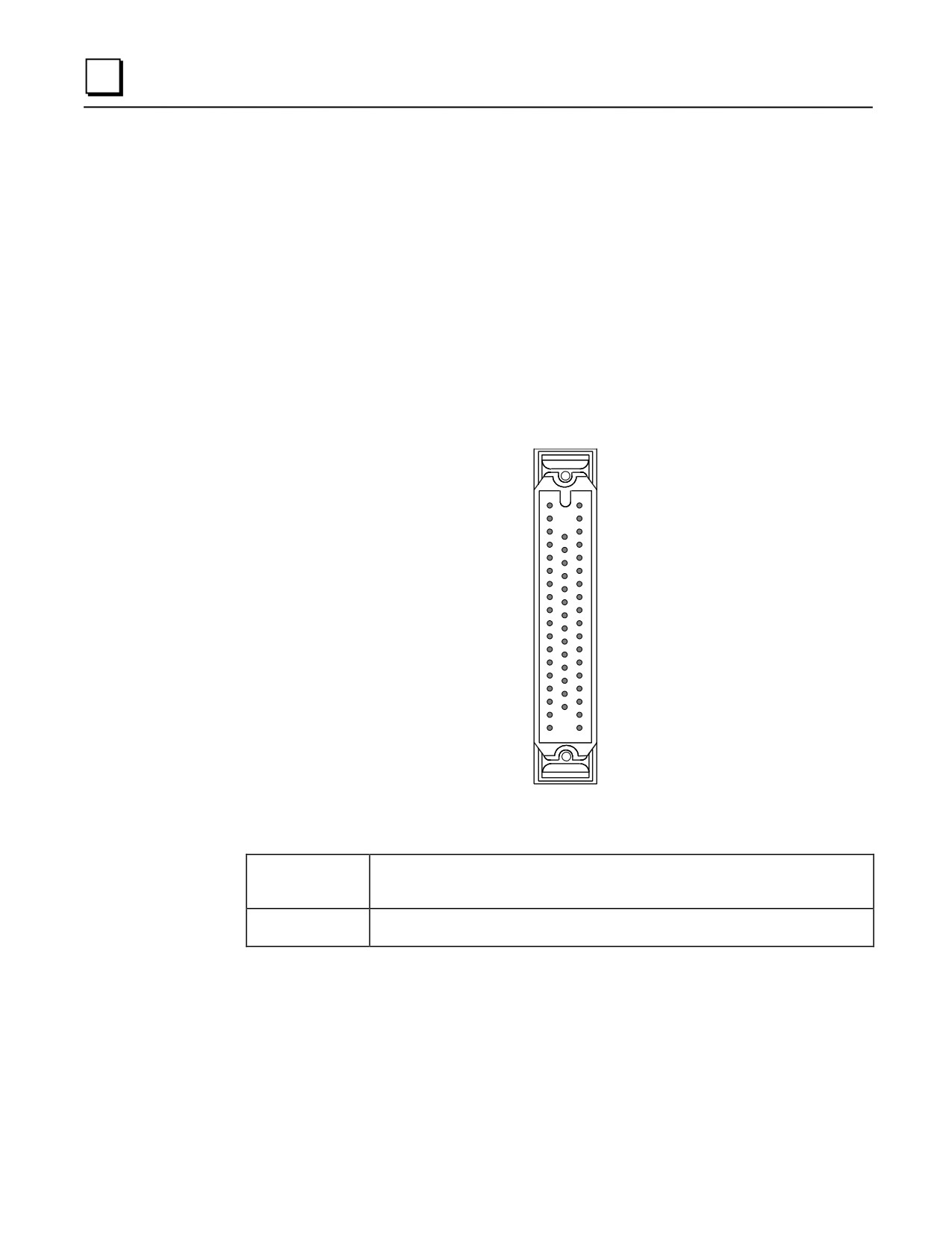
The connector on the module is oriented with the notch towards the top of the module with pin 1 at
the top of the right row of pins as you are looking at it, as shown below:
33
1
19
32
50
18
Cable Specifications
Cable Length
IC693CBL306
3 feet (1 meter),
IC693CBL307
6 feet (2 meters)
Connectors
50-pin female Honda on end that connects to male connector on module.
50-pin male connector on end that connects to Connector Interface Assembly.
We recommend the use of a terminal block for connecting field wiring to the 50-pin high-density
I/O modules. The use of a connector interface provides a convenient method of terminating field
wiring to the modules.
Weidmuller Electrical and Electronic Connection Systems makes a suitable terminal block
assembly RS-MR 50 B, catalog number 912263 (female Honda connector). An example of using
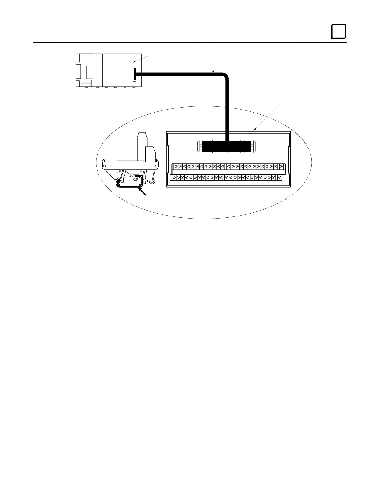
an IC693CBL306 or 307 cable to connect a 32 point I/O module to one of these terminal blocks is
shown in the following figure.
10-38
Series 90-30 PLC Installation and Hardware Manual - August 2002
GFK-0356Q
Cables
10
50-Pin, 32-Point
I/O Module
Extension Cable
SERIES 90-30 PLC
Weidmuller
Terminal BlocK
(DIN-Rail Mounted)
50
END
VIEW
1
26
27 28 29 30 31 32 33 34 35 36 37
38 39 40 41 42 43 44 45
46 47 48 49
50
1
2
3
4
5
6
7
8
9
10 11 12
13 14
15 16 17 18
19
20
21 22 23 24
25
TOP
Mounts
VIEW
oDIN-
Rail
Figure 10-27. 32 Point I/O Module to Weidmuller Terminal Block Assembly
GFK-0356Q
Chapter 10 Cables
10-39
10
IC693CBL308/309
I/O Cables (50-Pin) for 32 Point Modules
Function of cable
This cable is used with 32 point High Density modules that have a 50-pin Honda connector
mounted on the front of the module. The modules that use these cable are: IC693MDL652,
IC693MDL653, IC693MDL750, and IC693MDL751.
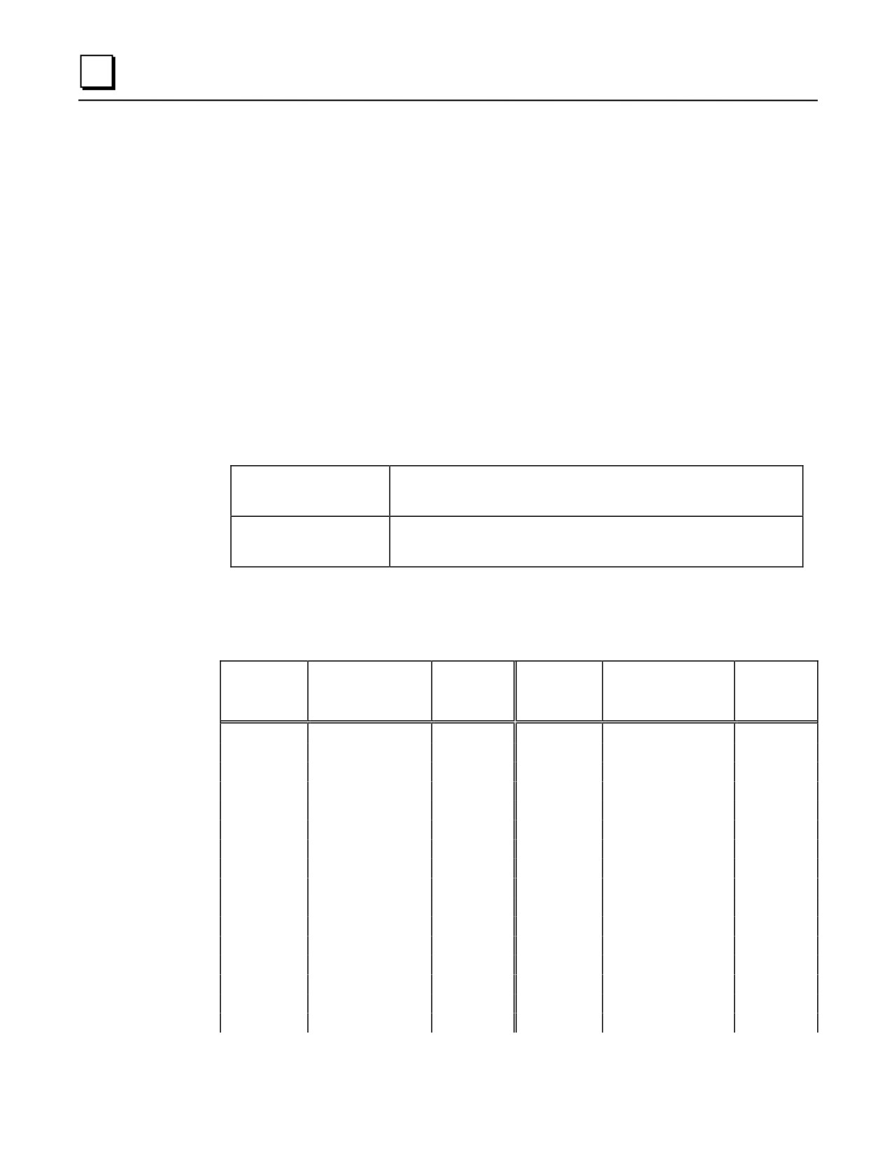
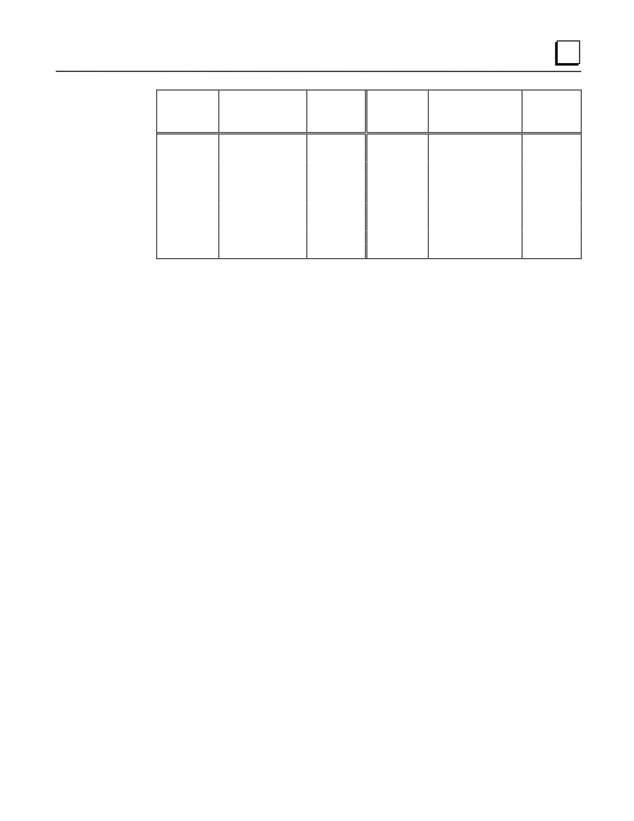
The I/O cables have a female connector on one end, and stripped and tinned wires on the other end.
Each of the stripped and tinned wires has a label attached to it for ease of identification. The
numbers on these labels correspond with the pin number of the connector wired to the opposite
end.
Specifications
Cable Length
IC693CBL308
3 feet (1 meter)
IC693CBL309
6 feet (2 meters)
Connectors
50-pin female Honda on end that connects to male connector on module.
Opposite end has stripped and tinned labeled wires for connection to
Connector Interface Assembly
Wiring Information
Table 10-3. Wire List for 32 Point I/O Cables
Connector
Label
Connector
Label
Pin
Color Code
Number
Pin
Color Code
Number
Number
Loose End
Number
Loose End
1
Black
1
26
White/Black/Violet
26
2
Brown
2
27
White/Black/Gray
27
3
Red
3
28
White/Brown/Red
28
4
Orange
4
29
White/Brown/Orange
29
5
Yellow
5
30
White/Brown/Yellow
30
6
Green
6
31
White/Brown/Green
31
7
Blue
7
32
White/Brown/Blue
32
8
Violet
8
33
White/Brown/Violet
33
9
Gray
9
34
White/Brown/Gray
34
10
White
10
35
White/Red/Orange
35
11
White/Black
11
36
White/Red/Yellow
36
12
White/Brown
12
37
White/Red/Green
37
13
White/Red
13
38
White/Red/Blue
38
14
White/Orange
14
39
White/Red/Violet
39
15
White/Yellow
15
40
White/Red/Gray
40
16
White/Green
16
41
White/Orange/Yellow
41
10-40
Series 90-30 PLC Installation and Hardware Manual - August 2002
GFK-0356Q
Cables
10
Connector
Label
Connector
Label
Pin
Color Code
Number
Pin
Color Code
Number
Number
Loose End
Number
Loose End
17
White/Blue
17
42
White/Orange/Green
42
18
White/Violet
18
43
White/Orange/Blue
43
19
White/Gray
19
44
White/Orange/Violet
44
20
White/Black/Brown
20
45
White/Orange/Gray
45
21
White/Black/Red
21
46
White/Yellow/Green
46
22
White/Black/Orange
22
47
White/Yellow/Blue
47
23
White/Black/Yellow
23
48
White/Yellow/Violet
48
24
White/Black/Green
24
49
White/Yellow/Gray
49
25
White/Black/Blue
25
50
White/Green/Blue
50
GFK-0356Q
Chapter 10 Cables
10-41
10
IC693CBL310
I/O Interface Cable (24-Pin) for 32 Point Modules
Note: This cable is obsolete. Please use IC693CBL327 and IC693CBL328.
See the data sheet for these cables for details. The replacement cables
have right-angle connectors to reduce the clearance space required in
front of the PLC.
Function of cable
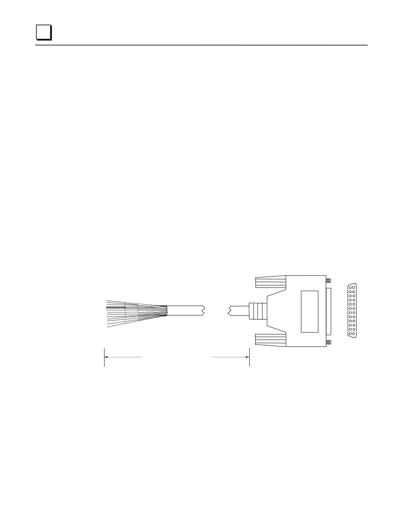
This 10' (3 meter) prewired cable was used with all Series 90-30 high-density (32 point) I/O
modules that use the Fujitsu 24-pin user I/O connector. Each of these modules has two of these
connectors mounted side-by-side. I/O Interface cables have a 24-pin female connector on one end
for connection to the module, and stripped and tinned wires on the other end. Catalog numbers for
32 point modules having two 24-pin connectors are: IC693MDL654, IC693MDL655,
IC693MDL752, and IC693MDL753.
Connections to module input circuits are made from the user’s input devices to two male (pin-type)
24-pin connectors (Fujitsu FCN-365P024-AU) mounted on the front of the module. The
connector mounted on the right of the module (front view) interfaces with groups A and B; the
connector on the left side of the module interfaces with groups C and D. If a different length cable
is required for connections to these modules, you can build your own cable (information on
building your own cable is found in the data sheet for cable IC693CBL315).
B1
A1
B12 A12
Length = 10’ (3 meters)
Connector: Fujitsu FCN-365S024-AU
Figure 10-28. IC693CBL310 Cable
10-42
Series 90-30 PLC Installation and Hardware Manual - August 2002
GFK-0356Q
Cables
10
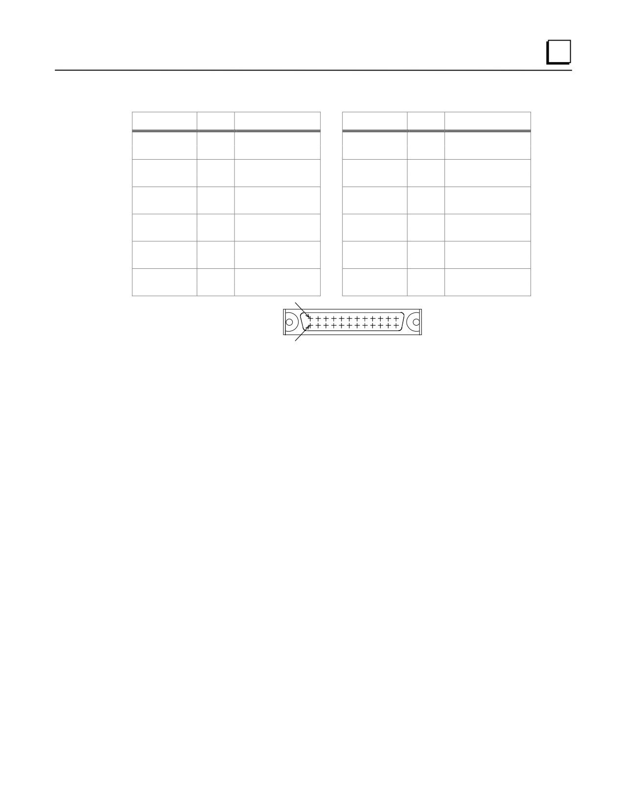
Table 10-4. Wire List for 24-Pin Connectors
Pin Number
Pair #
Wire Color Code
Pin Number
Pair #
Wire Color Code
A1
1
BLACK
B1
7
BLUE
A2
1
WHITE
B2
7
WHITE
A3
2
BROWN
B3
8
VIOLET
A4
2
WHITE
B4
8
WHITE
A5
3
RED
B5
9
GRAY
A6
3
WHITE
B6
9
WHITE
A7
4
ORANGE
B7
10
BROWN
A8
4
WHITE
B8
10
BLACK
A9
5
YELLOW
B9
11
RED
A10
5
WHITE
B10
11
BLACK
A11
6
GREEN
B11
12
ORANGE
A12
6
WHITE
B12
12
BLACK
B ROW
12
3 2 1
CONNECTOR
12
3 2 1
A ROW
NOTE
Each pair of wires should be tied together with heat
ubing for identification purposes. For example, a
p
iece of heat shrink tubing should be placed around the
BLACK and WHITE wire pair (Pair #1) that connect to
Pins A1 and A2, etc.
Replacement/Obsolescence Information
This cable became obsolete and was replaced by cable IC693CBL315 (now obsolete also).
The only difference between these two cables is in the wire color coding.
When cable IC693CBL315 became obsolete, the replacement for these cables became
IC693CBL327 and IC693CBL328. Cables IC693CBL310/315 have straight connectors.
Cables IC693CBL327/328 have right angle connectors. The right angle connectors require
less depth in front of the PLC, so allow the use of a smaller enclosure in some applications.
Data sheets for cables IC693CBL315 and IC693CBL327/328 can be found in this chapter.
Connector Depth for Cable IC693CBL310
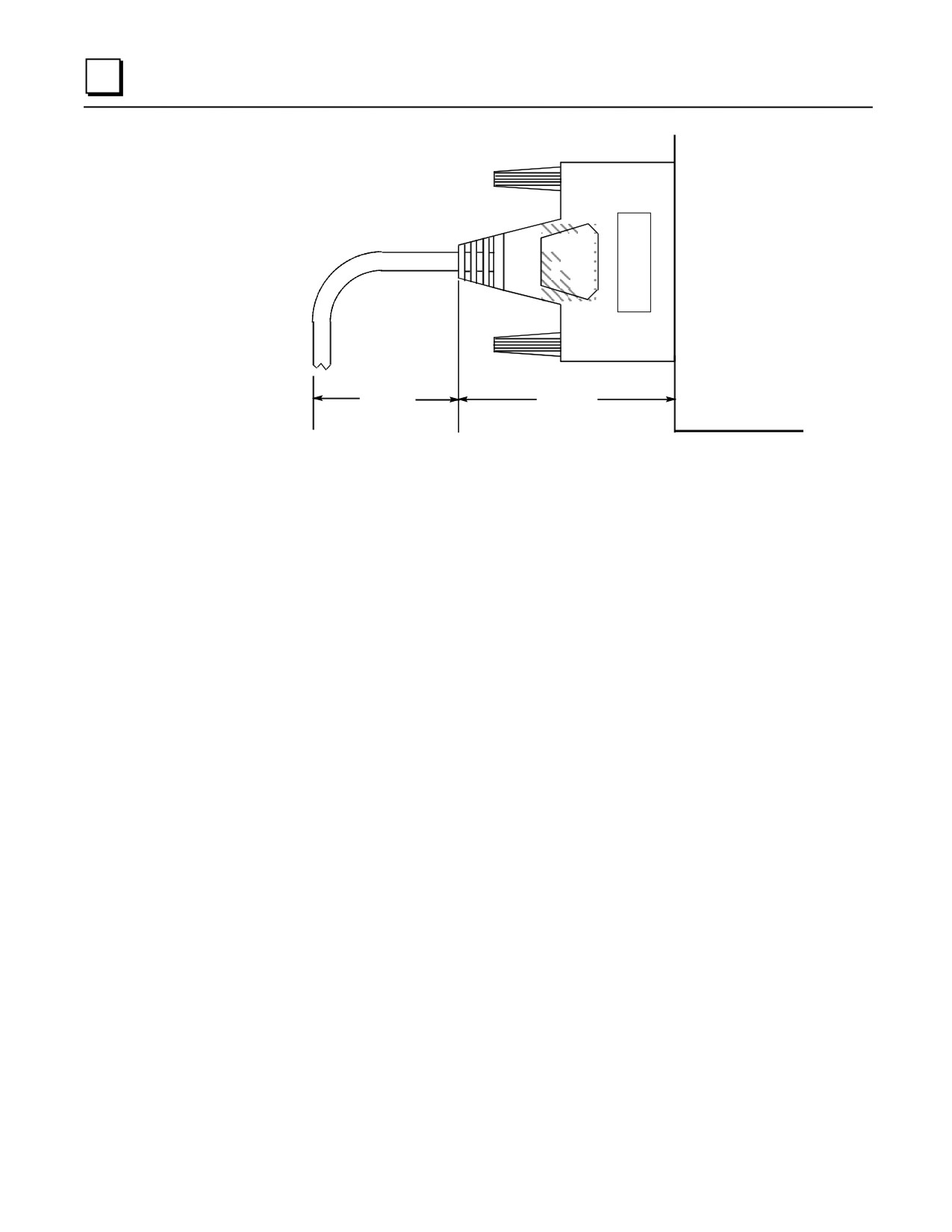
The following illustration shows the space required in front of the PLC when this cable is
connected to a module. The depth of the cabinet that the PLC is mounted in should allow for the
depth added by this connector.
GFK-0356Q
Chapter 10 Cables
10-43
10
PLC (Side View)
1.5-2.5"
2.187"
Typical
Figure 10-29. Dimensions for Depth of Connector in front of PLC
10-44
Series 90-30 PLC Installation and Hardware Manual - August 2002
GFK-0356Q
Cables
10
IC693CBL311/317/319/320
I/O Interface Cables for Power Mate APM Modules
Function of cable
The I/O Interface Cable assembly consists of a 24-pin I/O connector, a cable, and a 25-pin D-type
terminal block connector. This cable is used to connect the Power Mate APM Modules
(IC693APU301 and IC693APU302) to drives and machines. There are two male 24-pin
connectors mounted on the front of each Power Mate APM. Two of these I/O Interface cables are
required for connections to and from the drive and machine. Catalog number IC693CBL311 is 10
feet (3 meters) in length and IC693CBL319 is 3 feet (1 meter) in length. The cable wire code list
for these cables is provided in Table H-4.
An I/O cable assembly similar to IC693CBL311 and IC693CBL319, but with the drain shield wire
disconnected from pin B12 and brought outside of the cable housing through an 8” pigtail, is also
available in two lengths. Catalog number IC693CBL317 is 10 feet (3 meters) in length and
IC693CBL320 is 3 feet (1 meter) in length. This cable improves the Power Mate APM’s noise
immunity. The cable wire code list for these cables is provided in Table 10-5.
To make wiring to the drive and machine easier, each connector on the module is typically
connected by a short cable (the I/O Interface cable) to a terminal block. The cable that connects
from the I/O connector to an external terminal block can be shortened to meet the requirements of
your installation. See manuals GFK-0840 (standard mode) or GFK-0781 (follower mode) for
details on APM terminal blocks.
1 or 3 METERS
B1
A1
B12
A12
I/O
TERMINAL BLOCK
CONNECTOR
CONNECTOR
* Cable for IC693CBL311/319 shown. Cables IC693CBL317/320 have 8" external wire
connected to drain shield.
Figure 10-30. I/O Connector Cable Specifications
Specifications
Cable Length
10 feet (3 meters) and 3 feet (1 meter)
Connector
24-pin female, Fujitsu part number FCN-363J024 (crimp wire type.
GFK-0356Q
Chapter 10 Cables
10-45
10
Wiring Information
You must purchase the mating female (socket type) 24-pin connectors (which mate with the I/O
Connector on the faceplate of the APM). This connector is available under catalog number
IC693ACC317. This connector has a solder eyelet receptacle and is part of an accessory kit.
Optionally, other types of the 24-pin connector (for different physical connections) are also
available.
Catalog numbers for these connectors and their associated parts are listed in the following table.
The list includes catalog numbers for three types of connectors: solder pin, crimp pin, and ribbon
cable. Each accessory kit contains enough components (D-connectors, backshells, contact pins,
etc.) to assemble ten single-ended cables of the type specified for each kit.
Table 10-5. Catalog Numbers for 24-Pin Connector Kits
GE Fanuc
Vendor
Catalog Number
Catalog Number
Description
IC693ACC316
FCN-361J024-AU
Solder eyelet receptacle
(Solder Eyelet Type)
FCN-360C024-B
Backshell (for above)
IC693ACC317
FCN-363J024
Crimp wire receptacle
(Crimp Type)
FCN-363J-AU
Crimp pin (for above, 24 needed)
FCN-360C024-B
Backshell (for above)
IC693ACC318
FCN-367J024-AUF
IDC (ribbon) receptacle, closed cover
(Ribbon or IDC Type)
FCN-367J024-AUH
IDC (ribbon) receptacle, open cover
Note: Wire for cables is 12 twisted pairs, #24 AWG (0.22mm2).
Additional tools from Fujitsu are required to properly assemble the crimped contact and ribbon
cable type connectors. The solder eyelet connectors (as provided in IC693ACC316) do not require
any special tooling.
Crimped Contact Connectors (as provided in IC693ACC317) require:
Hand Crimping Tool
FCN-363T-T005/H
Contact Extraction Tool
FCN-360T-T001/H
Ribbon Cable Connectors (as provided in IC693ACC318) require:
Cable Cutter
FCN-707T-T001/H
Hand Press
FCN-707T-T101/H
Locator Plate
FCN-367T-T012/H
These tools need to be ordered from an authorized Fujitsu distributor. Three of the largest US
distributors for Fujitsu connectors are Marshall at (800)522-0084, Milgray at (800)MILGRAY, and
Vantage at (800)843-0707. If none of these distributors service your area, contact Fujitsu
Microelectronics in San Jose, California, USA via telephone at (408) 922-9000 or via fax at (408)
954-0616 for further information.
It is recommended that you order any necessary connector tooling with sufficient lead time to meet
your assembly requirements for these connectors. These tools are generally not stock items and
can have significant lead times from distribution. If you have any further questions about this
issue, please feel free to contact the GE Fanuc PLC Hotline at 1-800-GE FANUC (1-800-433-
2682) or 804-978-6036.
10-46
Series 90-30 PLC Installation and Hardware Manual - August 2002
GFK-0356Q
Cables
10
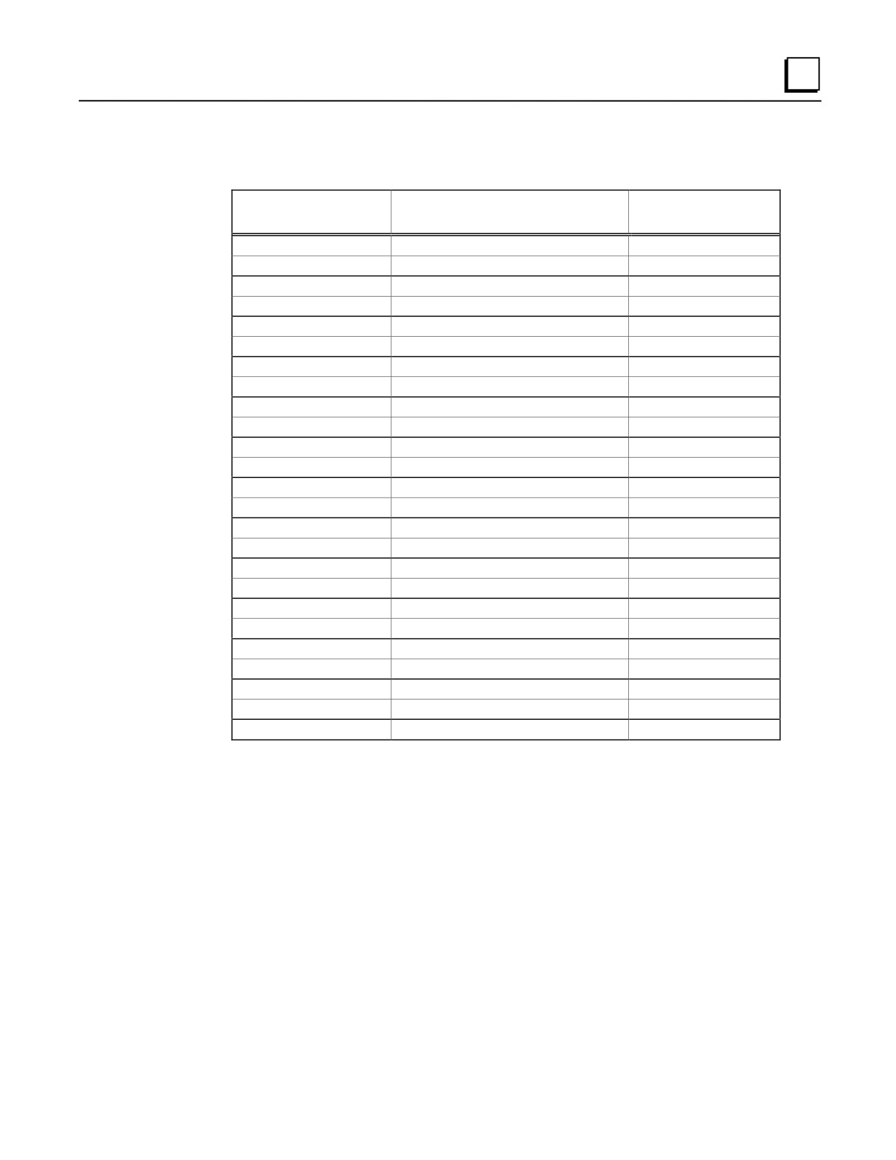
The following tables provides wiring information for the I/O Interface cables:
Table 10-6. I/O Cable Wire Coding for IC693CBL311 and IC693CBL319
I/O Connector
25-Pin Connector
Pin Number
Cable Wire
Terminal Number*
no connection
Wire 1 Pair 1
25
A1
Wire 2 Pair 1
12
B1
Wire 1 Pair 2
24
A2
Wire 2 Pair 2
11
B2
Wire 1 Pair 3
23
A3
Wire 2 Pair 3
10
B3
Wire 1 Pair 4
22
A4
Wire 2 Pair 4
9
B4
Wire 1 Pair 5
15
A5
Wire 2 Pair 5
2
B5
Wire 1 Pair 6
14
A6
Wire 2 Pair 6
1
B6
Wire 1 Pair 7
16
A7
Wire 2 Pair 7
3
B7
Wire 1 Pair 8
17
A8
Wire 2 Pair 8
4
B8
Wire 1 Pair 9
21
A9
Wire 2 Pair 9
8
B9
Wire 1 Pair 10
20
A10
Wire 2 Pair 10
7
B10
Wire 1 Pair 11
19
A11
Wire 2 Pair 11
6
B11
Wire 1 Pair 12
18
A12
Wire 2 Pair 12
5
B12
Drain Wire (Shield)
13
* Same as Terminal Block Terminal Number. See manuals GFK-0840 (standard mode) or GFK-0781 (follower
mode) for terminal block details.
GFK-0356Q
Chapter 10 Cables
10-47
10
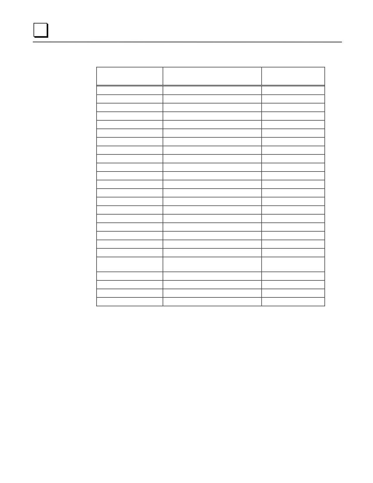
Table 10-7. I/O Cable Wire Coding for IC693CBL317 and IC693CBL320
I/O Connector
25-Pin Connector
Pin Number
Cable Wire Color Codes
Terminal Number 1
no connection
Wire 1 Pair 1 (Brown/Black)
25
A1
Wire 2 Pair 1 (Brown)
12
B1
Wire 1 Pair 2 (Red/Black)
24
A2
Wire 2 Pair 2 (Red)
11
B2
Wire 1 Pair 3 (Orange/Black)
23
A3
Wire 2 Pair 3 (Orange)
10
B3
Wire 1 Pair 4 (Yellow/Black)
22
A4
Wire 2 Pair 4 (Yellow)
9
B4
Wire 1 Pair 5 (Green/Black)
15
A5
Wire 2 Pair 5 (Green)
2
B5
Wire 1 Pair 6 (Blue/Black)
14
A6
Wire 2 Pair 6 (Blue)
1
B6
Wire 1 Pair 7 (Violet/Black)
16
A7
Wire 2 Pair 7 (Violet)
3
B7
Wire 1 Pair 8 (White/Black)
17
A8
Wire 2 Pair 8 (White)
4
B8
Wire 1 Pair 9 (Gray/Black)
21
A9
Wire 2 Pair 9 (Gray)
8
B9
Wire 1 Pair 10 (Pink/Black)
20
A10
Wire 2 Pair 10 (Pink)
7
B10
Wire 1 Pair 11 (Light Blue/
19
Black)
A11
Wire 2 Pair 11 (Light Blue)
6
B11
Wire 1 Pair 12 (Light Green/Black)
18
A12
Wire 2 Pair 12 (Light Green)
5
External Ring Terminal
Drain Wire (Shield) 2
13
1
Same as Terminal Block Terminal Number.
2
16 gauge wire, green w/yellow tracer. 8” length (from back of connector), terminates with a
#10 ring terminal.
10-48
Series 90-30 PLC Installation and Hardware Manual - August 2002
GFK-0356Q
Cables
10
IC693CBL315
I/O Interface Cable (24-Pin) for 32 Point Modules
Note: This cable became obsolete in late 1998. It was replaced by two cables:
IC693CBL327 and IC693CBL328. See the data sheet for these cables
for details. The replacement cables have right-angle connectors to
reduce the clearance space required in front of the PLC.
Function of cable
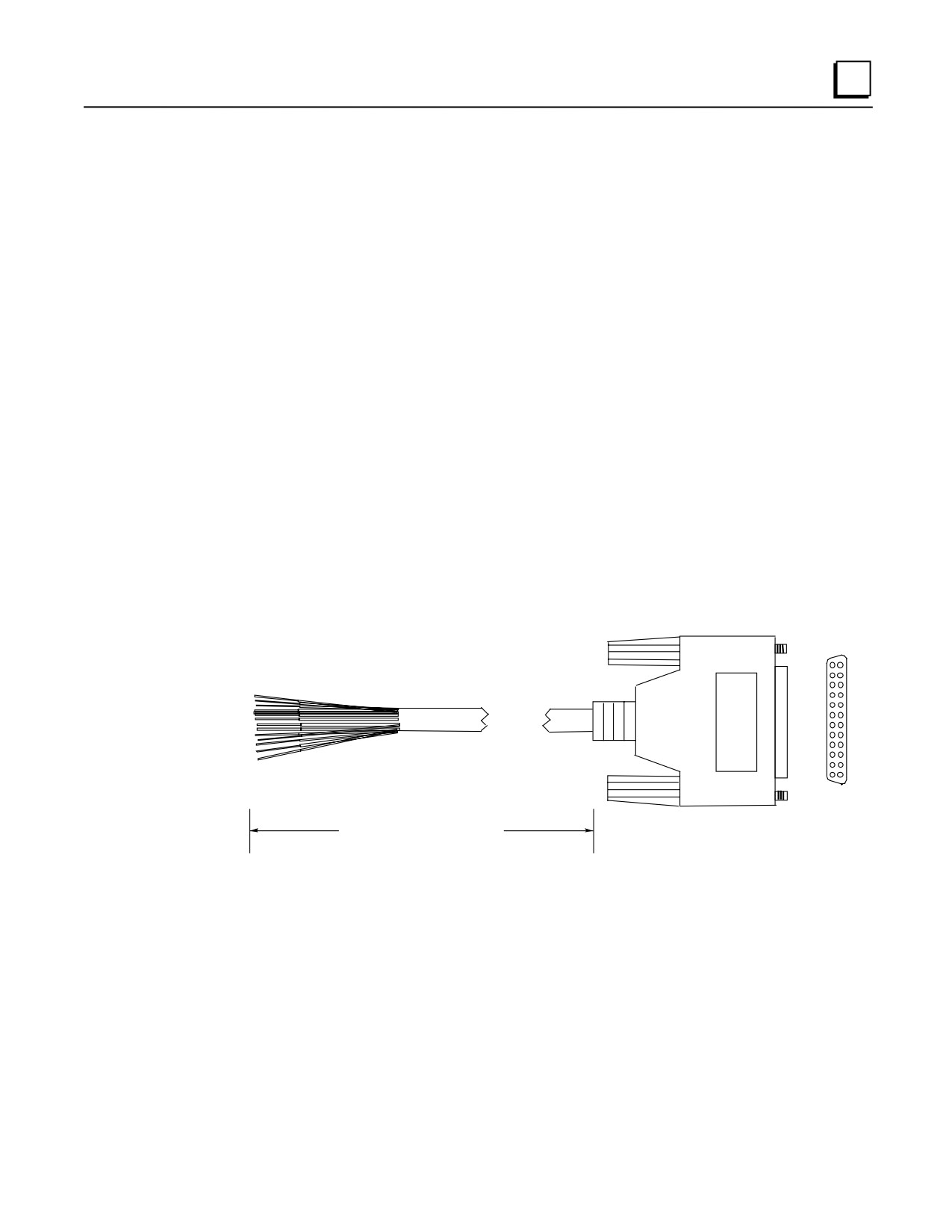
This prewired cable is available for use with all Series 90-30 high-density (32 point) I/O modules
that use the Fujitsu 24-pin user I/O connector. Each of these modules has two of these connectors
mounted side-by-side. I/O Interface cables have a 24-pin connector on one end for connection to
the module, and stripped and tinned wires on the other end. Catalog numbers for 32 point modules
having two 24-pin connectors are: IC693MDL654, IC693MDL655, IC693MDL752, and
IC693MDL753.
Connections to input circuits are made from the user’s input devices to two male (pin-type) 24-pin
connectors (Fujitsu FCN-365P024-AU) mounted on the front of the module. The connector
mounted on the right of the module (front view) interfaces with groups A and B; the connector on
the left side of the module interfaces with groups C and D. If a different length cable is required
for connections to these modules, you can build your own cable.
B1
A1
B12 A12
Length = 10’ (3 meters)
Connector: Fujitsu FCN-365S024-AU
Figure 10-31. IC693CBL315 Cable
Building Custom Length Cables for 24-Pin Connectors
Cables connecting the module to field devices can be built to length as required for individual
applications. You must purchase the mating female (socket type) 24-pin connectors. The 24-pin
connector kit can be ordered as an accessory kit from GE Fanuc. Catalog numbers for these
connectors and their associated parts are listed in the following table. The list includes catalog
numbers for three types of connectors: solder pin, crimp pin, and ribbon cable. Each accessory kit
contains enough components (D-connectors, backshells, contact pins, etc.) to assemble ten single-
ended cables of the type specified for each kit.
GFK-0356Q
Chapter 10 Cables
10-49
10
Table 10-8. Catalog Numbers for 24-Pin Connector Kits
GE Fanuc
Vendor
Catalog Number
Catalog Number
Description
IC693ACC316
FCN-361J024-AU
Solder eyelet receptacle
(Solder Eyelet Type)
FCN-360C024-B
Backshell (for above)
IC693ACC317
FCN-363J024
Crimp wire receptacle
(Crimp Type)
FCN-363J-AU
Crimp pin (for above, 24 needed)
FCN-360C024-B
Backshell (for above)
IC693ACC318
FCN-367J024-AUF
IDC (ribbon) receptacle, closed cover
(Ribbon or IDC Type)
FCN-367J024-AUH
IDC (ribbon) receptacle, open cover
Additional tools from Fujitsu are required to properly assemble the crimped contact and ribbon
cable type connectors. The solder eyelet connectors (as provided in IC693ACC316) do not require
any special tooling.
Crimped Contact Connectors (as provided in IC693ACC317) require :
Hand Crimping Tool
FCN-363T-T005/H
Contact Extraction Tool
FCN-360T-T001/H
Ribbon Cable Connectors (as provided in IC693ACC318) require :
Cable Cutter
FCN-707T-T001/H
Hand Press
FCN-707T-T101/H
Locator Plate
FCN-367T-T012/H
These tools need to be ordered from an authorized Fujitsu distributor. Three of the largest US
distributors for Fujitsu connectors are Marshall at (800)522-0084, Milgray at (800)MILGRAY, and
Vantage at (800)843-0707. If none of these distributors service your area, then contact Fujitsu
Microelectronics in San Jose, California, USA via telephone at (408) 922-9000 or via fax at (408)
954-0616 for further information.
It is recommended that you order any necessary connector tooling with sufficient lead time to meet
your assembly requirements for these connectors. These tools are generally not stock items and
can have significant lead times from distribution. If you have any further questions about this
issue, please feel free to contact the GE Fanuc PLC Technical Support Hotline at 1-800-GE
FANUC (1-800-433-2682), or International dial direct 804-978-6036.
Pin connections with color codes are shown in the following table. Cables are made of 12 twisted
pairs; wire size is #24 AWG (0.22mm2).
10-50
Series 90-30 PLC Installation and Hardware Manual - August 2002
GFK-0356Q
Cables
10
Table 10-9. Wire List for 24-Pin Connectors
Pin
Pair #
Wire Color Code
Pin Number
Pair #
Wire Color Code
Number
A1
1
BROWN
B1
7
VIOLET
A2
1
BROWN/BLACK
B2
7
VIOLET/BLACK
A3
2
RED
B3
8
WHITE
A4
2
RED/BLACK
B4
8
WHITE/BLACK
A5
3
ORANGE
B5
9
GRAY
A6
3
ORANGE/BLACK
B6
9
GRAY/BLACK
A7
4
YELLOW
B7
10
PINK
A8
4
YELLOW/BLACK
B8
10
PINK/BLACK
A9
5
DARK GREEN
B9
11
LIGHT BLUE
A10
5
DARK GREEN/BLACK
B10
11
LIGHT BLUE/BLACK
A11
6
DARK BLUE
B11
12
LIGHT GREEN
A12
6
DARK BLUE/BLACK
B12
12
LIGHT GREEN/BLACK
B ROW
12
3 2 1
CONNECTOR
A ROW
12
3 2 1
NOTE
Each wire pair has a solid color wire and that same color
wire with a black tracer. For example, Pair 1 has a solid
brown wire paired with a brown wire with a black tracer.
Replacement/Obsolescence Information
Cable IC693CBL315 (now obsolete also) replaced cable IC693CBL310 when that cable
became obsolete. The only difference between these two cables is in the wire color coding.
When cable IC693CBL315 became obsolete, the replacement for these cables became
IC693CBL327 and IC693CBL328. Cables IC693CBL310/315 have straight connectors.
Cables IC693CBL327/328 have right angle connectors. The right angle connectors require
less depth in front of the PLC, so allow the use of a smaller enclosure in some applications.
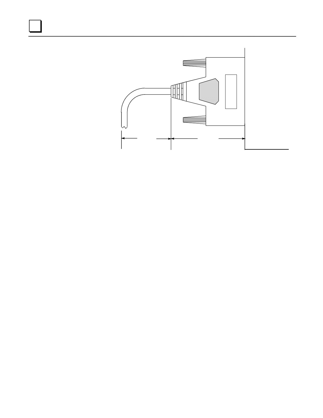
Connector Depth for IC693CBL315
The following illustration shows the space required in front of the PLC when this cable is
connected to a module. The depth of the cabinet that the PLC is mounted in should allow for the
depth added by this connector.
GFK-0356Q
Chapter 10 Cables
10-51
10
PLC (Side View)
1.5-2.5"
2.187"
Typical
Figure 10-32. Dimensions for Depth of Connector in front of PLC
10-52
Series 90-30 PLC Installation and Hardware Manual - August 2002
GFK-0356Q
Cables
10
IC693CBL316
Serial Cable, 9-Pin D-Shell to RJ-11 Connector
Description
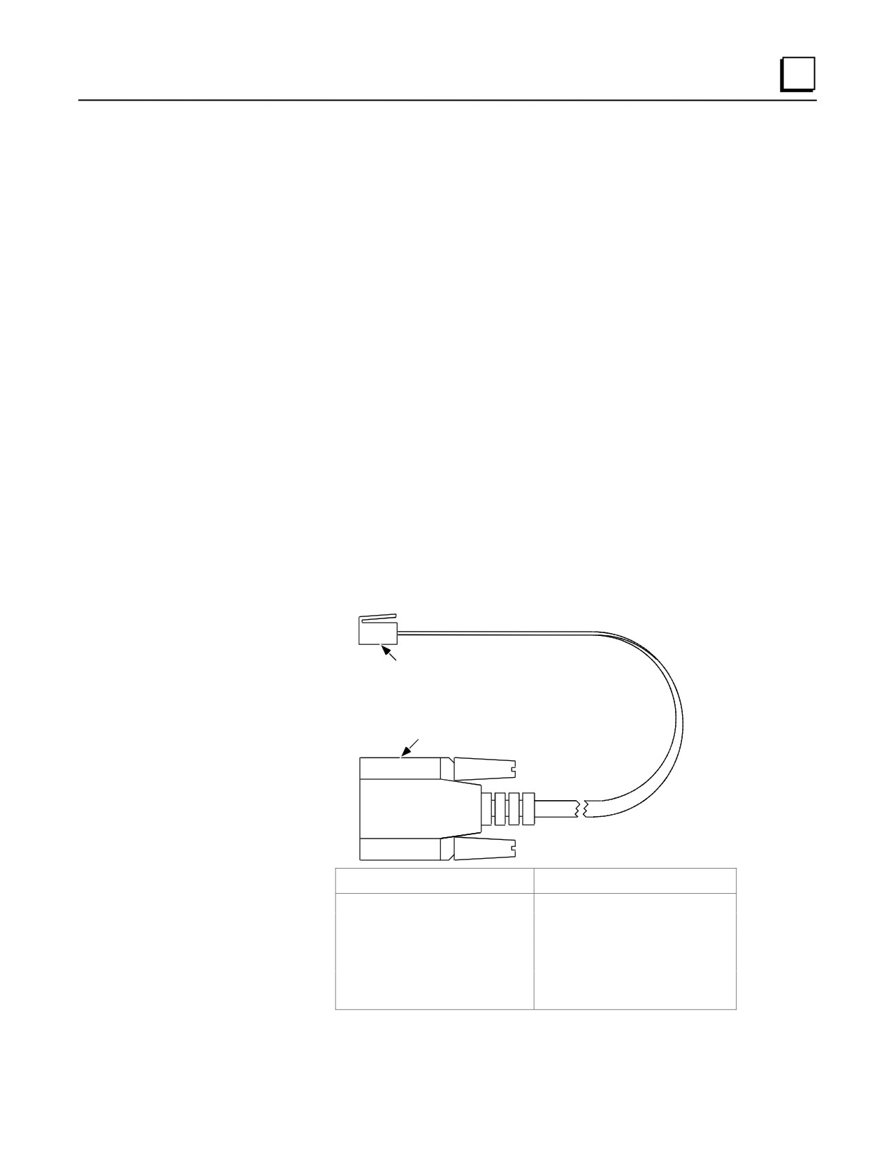
The IC693CBL316 cable is a 3-feet (1 meter) long, shielded cable with a 9-pin D-shell connector
one end and a 6-pin RJ-11 connector on the other. This cable is also known as a “Station Manager
Cable.” This cable can interconnect RS-232 ports without the need for a converter.
Typical Applications
Connect a Personal Computer’s 9-pin serial port to the RJ-11 faceplate serial port on CPUs
351, 352, and 363 for programming, configuring, firmware updating, and monitoring purposes.
Connect a Personal Computer’s 9-pin serial port to the Station Manager port on an
IC693CMM321 Ethernet module, a IC693CPU364 CPU, or a IC693CPU374 CPU module.
Connect a Personal Computer’s 9-pin serial port to an IC693DSM302 module’s RJ-11 COMM
port for loading motion programs (1 - 10) and firmware.
Connect a Personal Computer’s 9-pin serial port to an IC693DSM314 module’s RJ-11 COMM
port for loading firmware (motion programs for this module are loaded across the PLC
backplane).
RJ-11
CONNECTOR
9-PIN
FEMALE
CONNECTOR
9-Pin Connector Pin Number
RJ-11 Connector Pin Number
7
1 (Red)
2
2 (Yellow)
5
3 (Green)
5
4 (Brown)
3
5 (Black)
8
6 (Orange)
Figure 10-33. IC693CBL316A Serial Cable Illustration and Connector Pinouts
GFK-0356Q
Chapter 10 Cables
10-53
10
IC693CBL321/322/323
I/O Faceplate Connector to Terminal Block Connector, 24-Pin
Note: These cables became obsolete in late 1998. They were replaced by six
cables: IC693CBL329, IC693CBL330, IC693CBL331,
IC693CBL332, IC693CBL333, and IC693CBL334. See the data sheet
for these cables for details. The replacement cables have right-angle
connectors to reduce the clearance space required in front of the PLC.
Function of cable
These cables are used with 16-point I/O modules that are equipped with a TBQC I/O faceplate
adapter. Each cable has a straight 24-pin female connector on both ends. Each cable provides a
connection from the module to a connector mounted on a terminal block assembly. These cables
are wired pin-to-pin (that is, pin A1 to pin A1, pin A2 to pin A2, etc.). An I/O faceplate assembly
(catalog number IC693ACC334) is required which snaps onto the module in place of the module’s
standard 20-pin terminal block assembly. Five different terminal blocks are available to allow a
variety of I/O modules to use this accessory (see Appendix H for details on the TBQC assemblies).
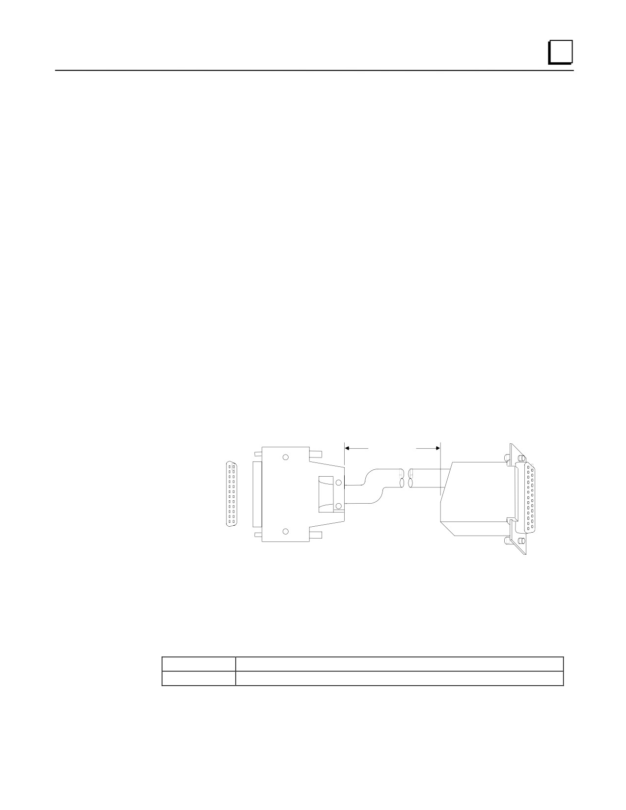
Cable Specifications
Item
Description
Cable Length*
IC693CBL321
3 feet (1 meter),
IC693CBL322
6 feet (2 meters)
IC693CBL323
1.5 feet (0.5 meters)
Cable Type:
12 twisted pairs with overall aluminum polyester shield and #24 AWG
drain wire.
24 Pin Female Connectors (2):
Equivalent to Fujitsu FCN-363J024, or equivalent.
* Length of cable is measured from backs of connector shells as shown in figure on next page.
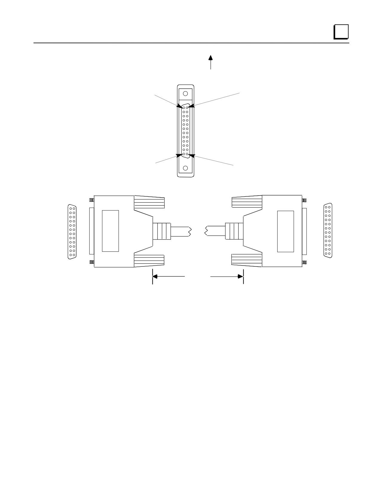
The connector on the I/O faceplate is oriented as shown below, with the rows labeled A1—A12
and B1—B12. A1 and B1 are towards the top of the module faceplate.
10-54
Series 90-30 PLC Installation and Hardware Manual - August 2002
GFK-0356Q
Cables
10
Top of I/O Faceplate
Pin B1
Pin A1
Pin B12
Pin A12
Figure 10-34. Connector Orientation on I/O Faceplate
B1
A1
A1
B1
B12
A12
A12
B12
Length*
IC693CBL321
3 feet (1 meter)
IC693CBL322
6 feet (2 meters)
IC693CBL323
1.5 feet (0.5 meter)
* Length is measured from backs of connector shells as shown above
Figure 10-35. I/O Faceplate to Terminal Block Cable
Connector Depth
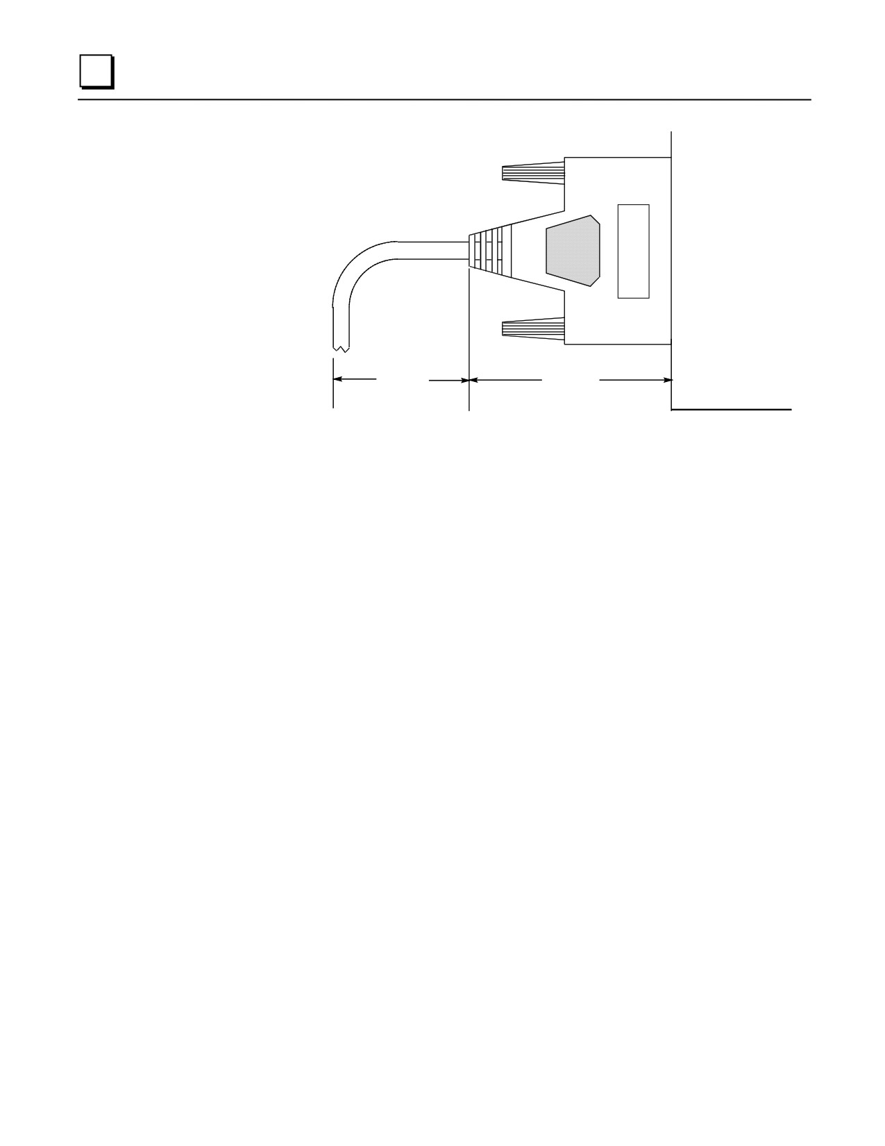
The following illustration shows the space required in front of the PLC when this cable is
connected to a module. The depth of the cabinet that the PLC is mounted in should allow for the
depth added by this connector.
GFK-0356Q
Chapter 10 Cables
10-55
10
PLC (Side View)
1.5-2.5"
2.187"
Typical
Figure 10-36. Dimensions for Depth of Connector in front of PLC
10-56
Series 90-30 PLC Installation and Hardware Manual - August 2002
GFK-0356Q
Cables
10
IC693CBL327/328
I/O Interface Cables with Right Angle 24-Pin Connector
Note: These cables replace obsolete I/O Interface cable IC693CBL315. These
replacement cables have right-angle connectors to reduce the clearance
space required in front of the PLC. These replacement cables use the
same pin-outs as the obsolete cables.
Description
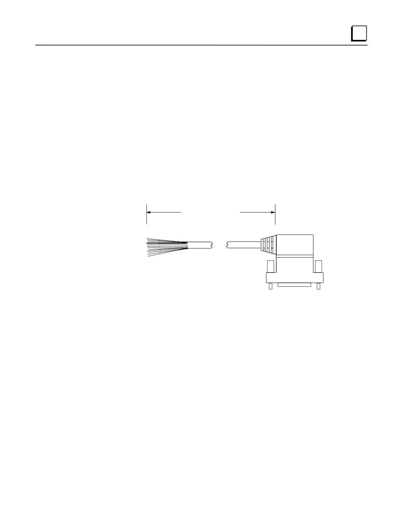
These cables each have a right-angle 24-pin connector on one end and a set of stripped wire ends
on the other. These two cables are identical except for their opposite connector orientations. This
difference in the cables’ connector orientations is for the purpose of matching the opposing
connector orientations on the dual-connector type of 32-point I/O modules.
10 Feet (3 Meters)
Figure 10-37. C693CBL327/328 Cables
Note
Each conductor in these 24-conductor cables has a current rating of 1.2 Amps. If
using these cables with a 16-point Output module with a higher output current
rating, you must use the lower value of 1.2 for the maximum load current rating .
If you have field devices that require more than 1.2 Amps, do not use a TBQC
assembly. Use the standard Terminal Board instead.
Applications
These cables are for use with Series 90-30 I/O modules that have the Fujitsu 24-pin user I/O
connector. There are two categories of these modules:
32 point modules with two 24-pin connectors (IC693MDL654, IC693MDL655,
IC693MDL752, and IC693MDL753). The IC693CBL327 cable is for the modules’ left side
connector (front view), and the IC693CBL328 cable is for the modules’ right side connector.
The modules’ right side connector interfaces with I/O circuit groups A and B; the modules’ left
side connector interfaces with groups C and D. See Chapter 7, “Input and Output Modules”
GFK-0356Q
Chapter 10 Cables
10-57
10
for a drawing of these modules. See GFK-0898, the Series 90-30 PLC I/O Module
Specifications Manual, for details about these modules.
16-point modules that are equipped with the TBQC I/O faceplate adapter. See Appendix H
for information on the TBQC (Terminal Block Quick Connector). Use the IC693CBL328
right side cable for this application.
If a different length cable is required, you can build your own cable, but only straight connector kits
are currently available. See “Building Custom Length Cables” below.
Specifications
Cable Length
10 feet (3 meters)
Connector
Fujitsu FCN-365S024-AU
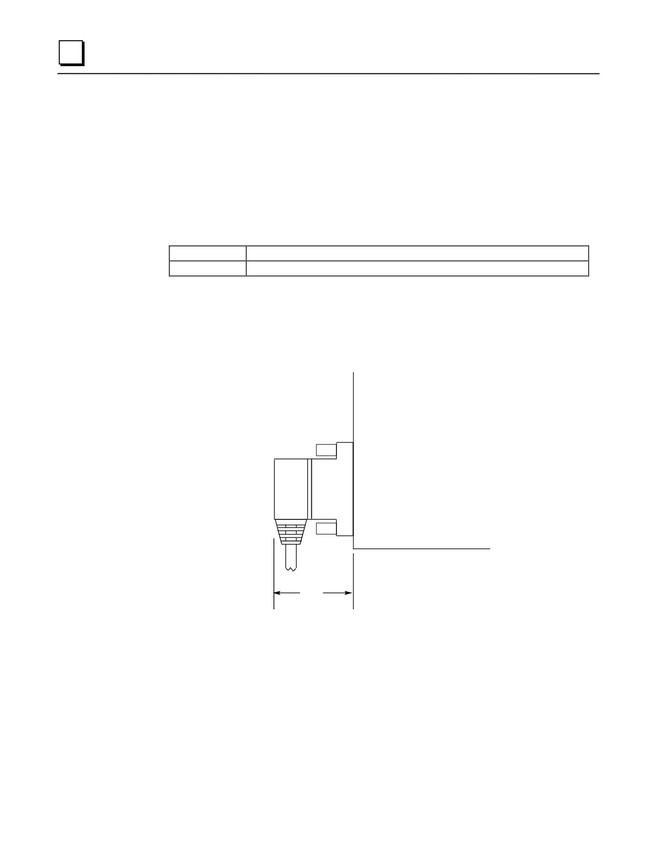
Connector Depth for Cables IC693CBL327/328
The following figure shows that these cables extend 2” out from the face of the modules they are
connected to. The depth of the cabinet that the PLC is mounted in should allow for the 2” depth
added by this connector.
Series 90-30
I/O Module
2.0"
Figure 10-38. Dimension for Depth of Connector for IC693CBL327/328
10-58
Series 90-30 PLC Installation and Hardware Manual - August 2002
GFK-0356Q
Cables
10
Building Custom Length 24-pin Connector Cables
Cables connecting the module to field devices can be built to length as required for individual
applications. You must purchase the mating female (socket type) 24-pin connectors. The 24-pin
connector kit can be ordered as an accessory kit from GE Fanuc. Catalog numbers for these
connectors and their associated parts are listed in the following table. The list includes catalog
numbers for three types of connectors: solder pin, crimp pin, and ribbon cable. Each accessory kit
contains enough components (D-connectors, backshells, contact pins, etc.) to assemble ten single-
ended cables of the type specified for each kit.
Table 10-10. Catalog Numbers for 24-Pin Connector Kits
GE Fanuc
Vendor
Catalog Number
Catalog Number
Description
IC693ACC316
FCN-361J024-AU
Solder eyelet receptacle
(Solder Eyelet Type)
FCN-360C024-B
Backshell (for above)
IC693ACC317
FCN-363J024
Crimp wire receptacle
(Crimp Type)
FCN-363J-AU
Crimp pin (for above, 24 needed)
FCN-360C024-B
Backshell (for above)
IC693ACC318
FCN-367J024-AUF
IDC (ribbon) receptacle, closed cover
(Ribbon or IDC Type)
FCN-367J024-AUH
IDC (ribbon) receptacle, open cover
Additional tools from Fujitsu are required to properly assemble the crimped contact and ribbon
cable type connectors. The solder eyelet connectors (as provided in IC693ACC316) do not require
any special tooling.
Crimped Contact Connectors (as provided in IC693ACC317) require :
Hand Crimping Tool
FCN-363T-T005/H
Contact Extraction Tool
FCN-360T-T001/H
Ribbon Cable Connectors (as provided in IC693ACC318) require :
Cable Cutter
FCN-707T-T001/H
Hand Press
FCN-707T-T101/H
Locator Plate
FCN-367T-T012/H
These tools need to be ordered from an authorized Fujitsu distributor. Three of the largest US
distributors for Fujitsu connectors are Marshall at (800)522-0084, Milgray at (800)MILGRAY, and
Vantage at (800)843-0707. If none of these distributors service your area, then contact Fujitsu
Microelectronics in San Jose, California, USA via telephone at (408) 922-9000 or via fax at (408)
954-0616 for further information.
It is recommended that you order any necessary connector tooling with sufficient lead time to meet
your assembly requirements for these connectors. These tools are generally not stock items and
can have significant lead times from distribution. If you have any further questions about this
issue, please feel free to contact the GE Fanuc PLC Technical Support Hotline at 1-800-GE
FANUC (1-800-433-2682), or International dial direct 804-978-6036.
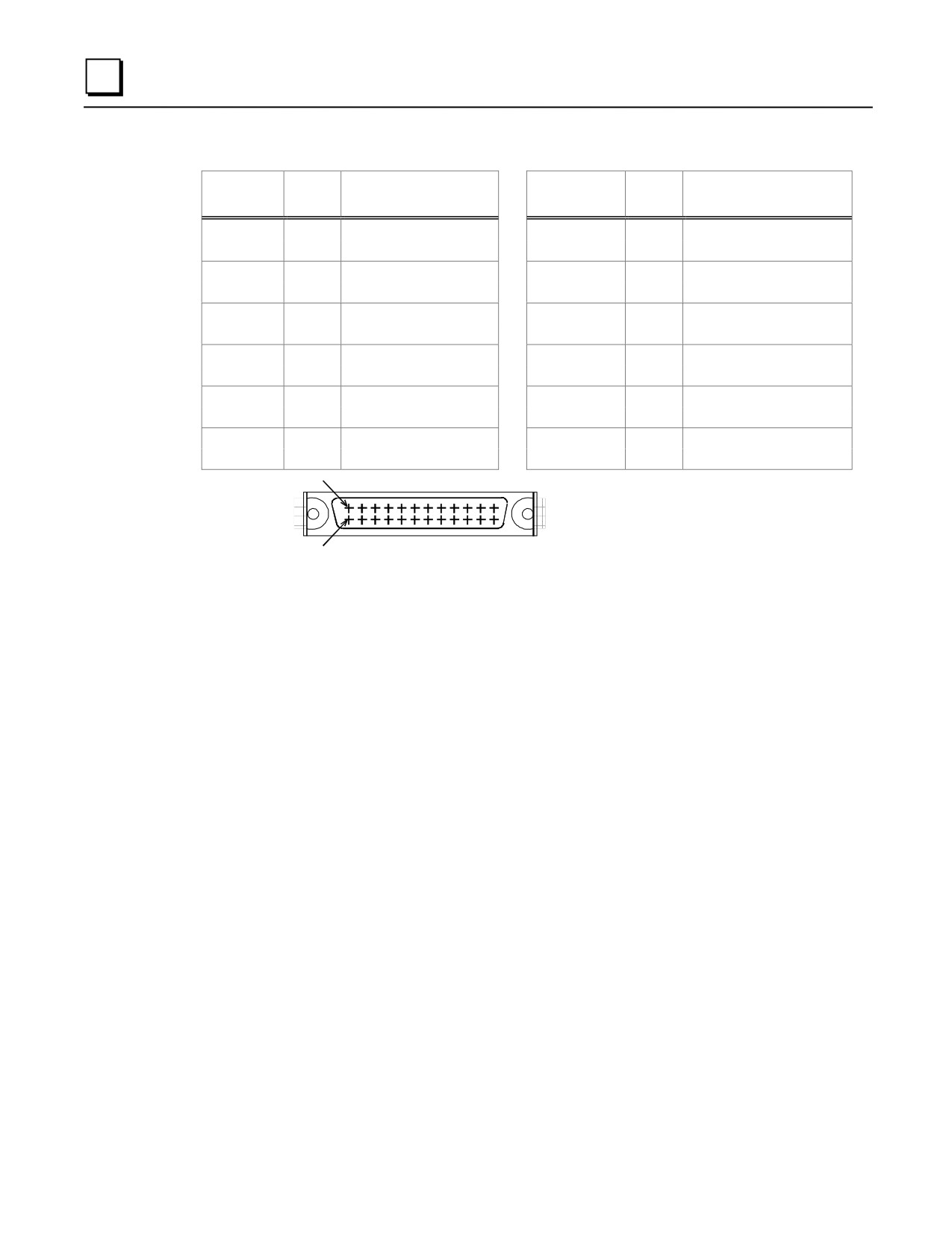
Pin connections with color codes are shown in the following table. Cables are made of 12 twisted
pairs; wire size is #24 AWG (0.22mm2).
GFK-0356Q
Chapter 10 Cables
10-59
10
Table 10-11. Wire List for 24-Pin Connectors
Pin
Pair #
Wire Color Code
Pin Number
Pair #
Wire Color Code
Number
A1
1
BROWN
B1
7
VIOLET
A2
1
BROWN/BLACK
B2
7
VIOLET/BLACK
A3
2
RED
B3
8
WHITE
A4
2
RED/BLACK
B4
8
WHITE/BLACK
A5
3
ORANGE
B5
9
GRAY
A6
3
ORANGE/BLACK
B6
9
GRAY/BLACK
A7
4
YELLOW
B7
10
PINK
A8
4
YELLOW/BLACK
B8
10
PINK/BLACK
A9
5
DARK GREEN
B9
11
LIGHT BLUE
A10
5
DARK GREEN/BLACK
B10
11
LIGHT BLUE/BLACK
A11
6
DARK BLUE
B11
12
LIGHT GREEN
A12
6
DARK BLUE/BLACK
B12
12
LIGHT GREEN/BLACK
B ROW
12
3 2 1
CONNECTOR
A ROW
12
3 2 1
NOTE
Each wire pair has a solid color wire and that same color
wire with a black tracer. For example, Pair 1 has a solid
brown wire paired with a brown wire with a black tracer.
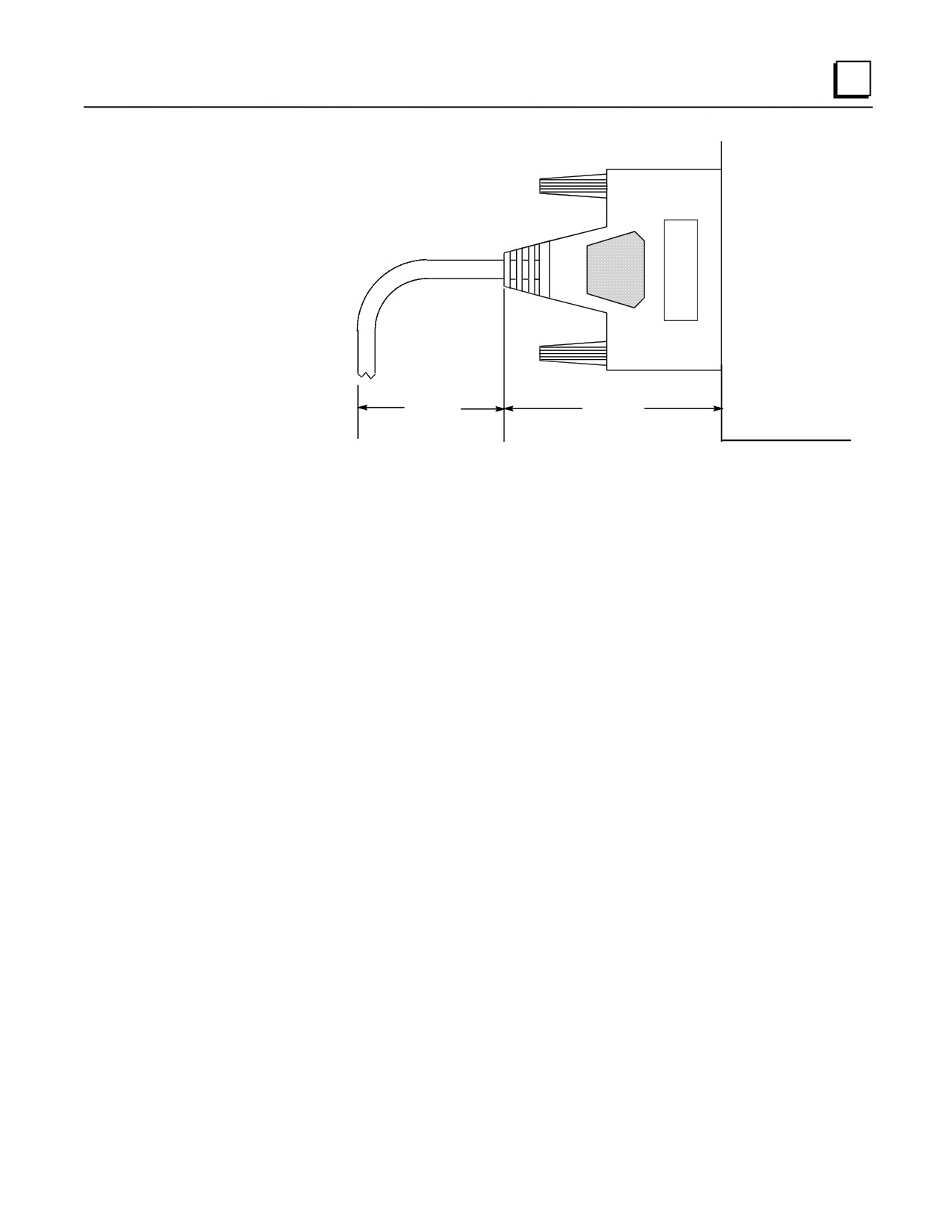
Connector Depth for Custom Built Cables
Because custom built cables use a straight connector, they require more space in front of the PLC
than is required for a factory built cable, which has a right-angle connector. The following figure
shows the space required in front of the PLC when this cable is connected to a module. The depth
of the cabinet that the PLC is mounted in should allow for the depth added by this connector.
10-60
Series 90-30 PLC Installation and Hardware Manual - August 2002
GFK-0356Q
Cables
10
PLC (Side View)
1.5-2.5"
2.187"
Typical
Figure 10-39. Dimensions for Depth of Connector in front of PLC for Custom Built Cables
Possible Uses for These Cables (Factory or Custom Built)
Connecting from the 24-pin connectors on a 32-point module to either a user-supplied terminal
strip/block or directly to I/O field devices (switches, lights, etc.).
Connecting from the 24-pin connector on a 16-point module that has a TBQC I/O faceplate
adapter to either a user-supplied terminal strip/block or directly to I/O field devices (switches,
lights, etc.). Use the right side cable, IC693CBL328, for this purpose. See Appendix H for
information about TBQC (Terminal Block Quick Connect) options.
Connecting from the 24-pin connectors on a 32-point module through a conduit to a Terminal
Block Quick Connect terminal block. This can be accomplished by attaching one of the
optional 24-pin connectors to the stripped end after pulling the cable through the conduit. See
the section “Building Custom Length Cables” for information on the connector options. See
Appendix H for information about TBQC (Terminal Block Quick Connect) options.
Connecting from the connector on a 16-point module that has a TBQC I/O faceplate adapter
through a conduit to a TBQC terminal block. This can be accomplished by attaching one of
the optional 24-pin connectors to the stripped end after pulling the cable through the conduit.
Use the right side cable, IC693CBL328, for this purpose. See the section “Building Custom
Length Cables” for information on the connector options. See Appendix H for information
about TBQC (Terminal Block Quick Connect) options.
GFK-0356Q
Chapter 10 Cables
10-61
10
IC693CBL329/330/331/332/333/334 Cables
24-Pin I/O Faceplate Connector to Terminal Block Connector
Note: These cables replace obsolete cables IC693CBL321/322/323. The
obsolete cables had straight connectors. These replacement cables have
right-angle connectors to reduce the clearance space required in front of
the PLC. They use the same pin-outs as the obsolete cables.
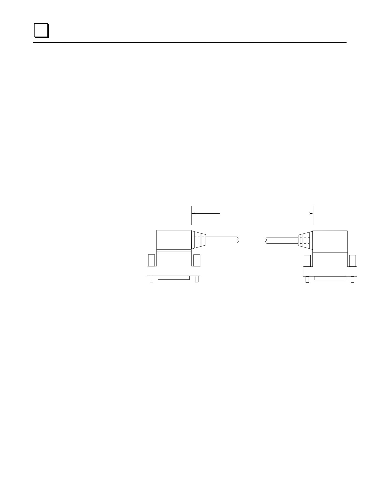
Description
These cables all have a right-angle 24-pin connector on each end. They are identical except for
connector orientation (right side and left side types) and cable length. The difference in connector
orientation is to allow them to work with the dual-connector type of 32-point I/O modules. These
cables are wired pin-to-pin (that is, pin A1 to pin A1, pin A2 to pin A2, etc.). Similar cables are
available in a 3 meter length that have a right angle connector on one end and stripped leads on the
other (see the data sheet for the IC693CBL327/328 cables for further information).
Cable Length (see table)
Figure 10-40. IC693CBL329/330/331/332/333/334 Cables
Note
Each conductor in these 24-conductor cables has a current rating of 1.2 Amps. If
using these cables with a 16-point Output module with a higher output current
rating, you must use the lower value of 1.2 for the maximum load current rating .
If you have field devices that require more than 1.2 Amps, do not use a TBQC
assembly. Use the standard Terminal Board instead.
10-62
Series 90-30 PLC Installation and Hardware Manual - August 2002
GFK-0356Q
Cables
10
Table 10-12. TBQC Cable Cross-Reference Table
Cable Catalog
Cable Description
Replaces Obsolete
Number
and Length
Cable Number
IC693CBL329
Dual 24-pin, 90 deg. connectors, Left Side
IC693CBL321
Cable length = 1.0 Meter
IC693CBL330
Dual 24-pin, 90 deg. connectors, Right Side
IC693CBL321
Cable length = 1.0 Meter
IC693CBL331
Dual 24-pin, 90 deg. connectors, Left Side
IC693CBL322
Cable length = 2.0 Meters
IC693CBL332
Dual 24-pin, 90 deg. connectors, Right Side
IC693CBL322
Cable length = 2.0 Meters
IC693CBL333
Dual 24-pin, 90 deg. connectors, Left Side
IC693CBL323
Cable length = 0.5 Meter
IC693CBL334
Dual 24-pin, 90 deg. connectors, Right Side
IC693CBL323
Cable length = 0.5 Meter
Cable Kits
IC693CBK002
Cable Kit. Includes both the IC693CBL329 (left side) and IC693CBL330 (right
side) cables
IC693CBK003
Cable Kit. Includes both the IC693CBL331 (left side) and IC693CBL332 (right
side) cables
IC693CBK004
Cable Kit. Includes both the IC693CBL333 (left side) and IC693CBL334 (right
side) cables
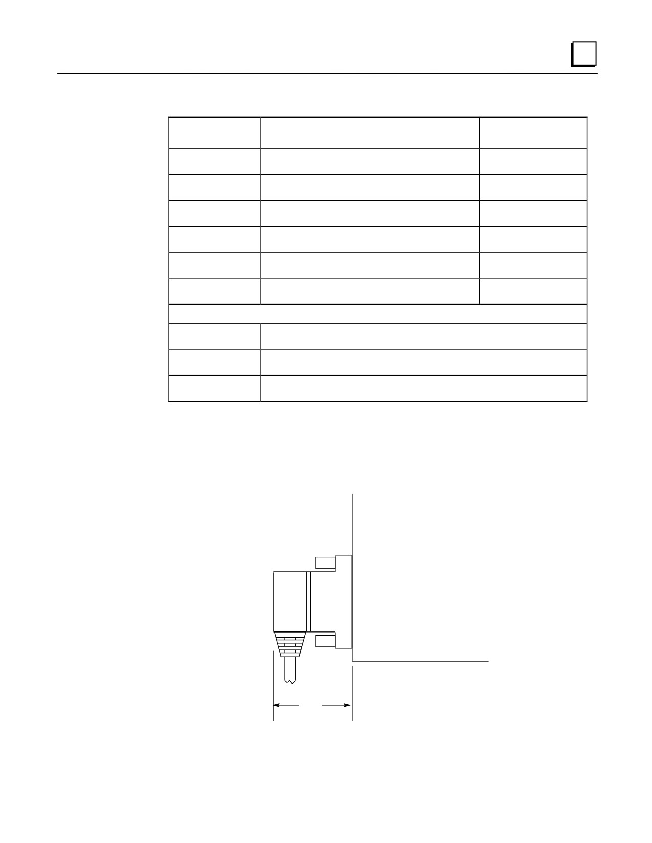
Connector Depth
The following figure shows that the cable connectors extend 2” out from the face of the Series 90-
30 modules they are connected to. The depth of the cabinet that the PLC is mounted in should
allow for the 2” depth added by this connector.
Series 90-30
I/O Module
2.0"
Figure 10-41. Dimension for Depth of Connector
GFK-0356Q
Chapter 10 Cables
10-63
10
Applications
These cables connect from Series 90-30 I/O modules that use the Fujitsu 24-pin I/O connector to
Terminal Block Quick Connect (TBQC) blocks. There are two categories of these modules:
32 point modules with two 24-pin connectors: IC693MDL654, IC693MDL655,
IC693MDL752, and IC693MDL753. The IC693CBL329/331/333 cables are for the modules’
left side connector (front view), and the IC693CBL330/332/334 cables are for the modules’
right side connector. The modules’ right side connector interfaces with I/O circuit groups A
and B; the modules’ left side connector interfaces with groups C and D. The other end of the
cables connect to the TBQC IC693ACC337 terminal block. See GFK-0898, the Series 90-30
PLC I/O Module Specifications Manual, for details about these modules. See Appendix H for
information on the TBQC components.
16-point modules that are equipped with the TBQC I/O faceplate adapter. Use the
IC693CBL330/332/334 right side cables for this application. See Appendix H for information
on the TBQC (Terminal Block Quick Connector) components.
10-64
Series 90-30 PLC Installation and Hardware Manual - August 2002
GFK-0356Q
Cables
10
IC693CBL340/341 PTM Interface Cables
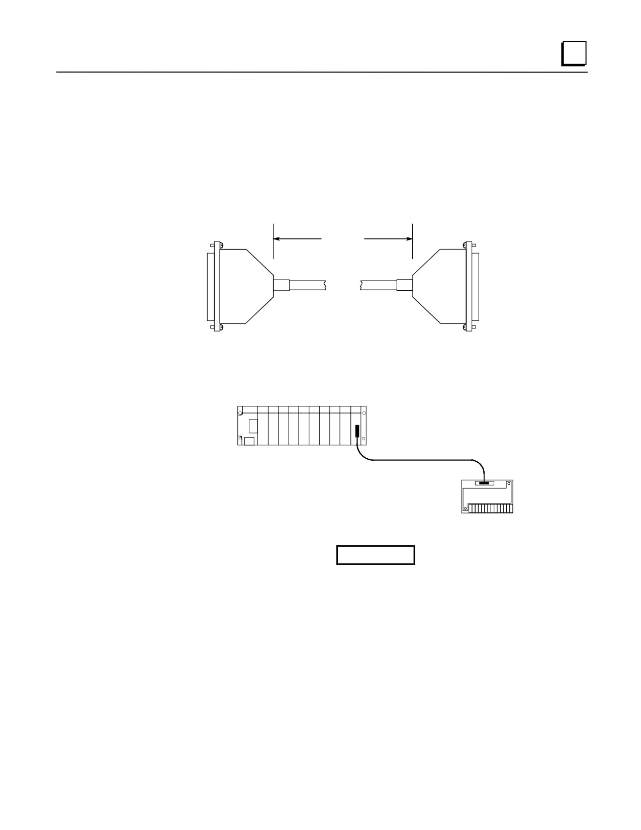
These cables connect the PTM Processing module to the PTM Interface board. The only difference
between the two cables is their lengths:
• IC693CBL340 is 19 inches (0.5 meter) long
• IC693CBL341 is 39 inches (1 meter) long
Length*
PTM Interface Cable
*Length of IC693CBL340 Cable is 19" (0.50 meter)
*Length of IC693CBL341 Cable is 39" (1 meter)
Figure 10-42. Figure IC693CBL340/341 PTM Interface Cables
Series 90-30 PLC
Processing Module
PTM
IC693CBL340/341 PTM Cable
Interface Board
Figure 10-43. PTM Component Mounting and Cable Connection
Warning
The PTM Interface board connects to hazardous voltages. Before installing,
testing, or troubleshooting this board, you should refer to the complete
instructions in this manual. Failure to follow the guidelines in the PTM
User’s Manual may result in personal injury, equipment damage, or both.
GFK-0356Q
Chapter 10 Cables
10-65
10
PTM Products Ordering Information
The Processing module and its Interface board are considered to be a matched set. Therefore, they
are not sold separately. The two cables, however, may be ordered as separate items. There are four
catalog numbers in the PTM product line:
• IC693PTM100 - Contains the Processing module, its matched Interface board, and the
19” (0.5 meter) interface cable.
• IC693PTM101 - Contains the Processing module, its matched Interface board, and the
39” (1 meter) interface cable.
• IC693CBL340 - 19” (0.5 meter) interface cable.
• IC693CBL341 - 39” (1 meter) interface cable.
Checking the IC693CBL340/341 Cables
The following information is supplied for the purpose of troubleshooting only (making continuity
checks of the cable). These cables have straight through connections (pin 1 connects to pin 1, pin 2
connects to pin 2, etc.), although some pins have no connections. One end is connected to a male,
all plastic DB-25 connector. The other end is connected to a female, all plastic DB-25 connector.
The cable is a twisted-pair type, connected to minimize noise and crosstalk between signals.
Warning
These cables connect to a circuit board that has hazardous voltages present.
These cables are carefully made to ensure the safety of the user and
associated equipment. Therefore, we recommend you use only factory-built
cables.
10-66
Series 90-30 PLC Installation and Hardware Manual - August 2002
GFK-0356Q