FANUC Series 90-30 PLC. Installation and Hardware Manual (GFK-0356Q) - page 7
8
Genius Hand-Held Monitor
The Genius Hand-Held Monitor can be used to display the GBC bus address, its software version,
and the Series Six register address configured for global data. HHM version IC660HHM501H
(revision 4.5) or later is required. There is no Hand-Held Monitor connector on the GBC module,
but a Hand-Held Monitor can communicate with the GBC while connected to any other device on
the bus. Optionally, an additional HHM mating connector can be installed on the bus near the
GBC.
Hand-Held Programmer
The GBC can be configured using a Series 90-30 Hand-Held Programmer (IC693PRG300).
Genius I/O Blocks
Genius I/O blocks can be present on the same bus as the GBC. However, because the Bus
Controller is not compatible with older phase A blocks, they should not be installed on the same
bus.
Genius Bus
The Genius bus is a shielded twisted-pair wire, daisy-chained between devices, and terminated at
both ends. Proper cable selection is critical to successful operation of the system. Suitable cable
types are listed in GEK-90486-1, the Genius I/O System and Communications User’s Manual.
Diagnostics
Genius blocks and other devices on the bus automatically report faults, alarms and certain other
predefined conditions to the PLC.
INPUTS AND FAULT MESSAGE
FROM BLOCK 3
GBC
1
2
3
4
TOKEN
F
F
F
FAULT
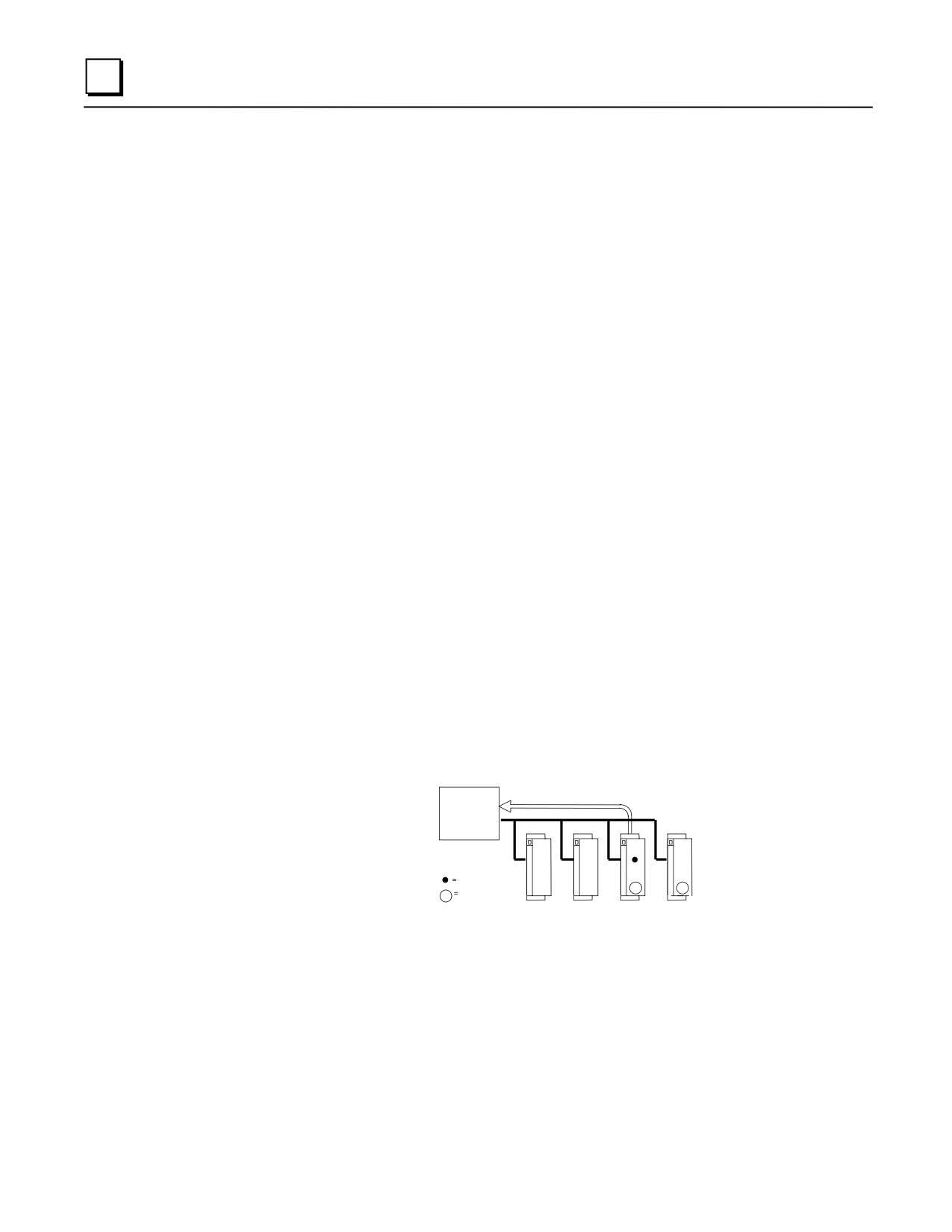
Only one diagnostic message can be sent during any bus scan. If a fault message has already been
sent (by another device) during that scan, a device saves its own diagnostic message until the next
available bus scan. For example, if the communications token is currently at device 3, and faults
occur at devices 3 and 4 at the same time, device 3 can send its diagnostic message if another
message has not already been sent. Device 4 must wait at least one more bus scan to send its
diagnostic message.
The GBC stores any diagnostic messages it receives. They are read automatically by the Series 90-
30 CPU. Faults can then be displayed in the fault table using the programming software. A Genius
Hand-held Monitor must be used to clear the faults from the fault table.
8-8
Series 90-30 PLC Installation and Hardware Manual - August 2002
GFK-0356Q

8
Datagrams
The Series 90-30 GBC supports all Genius datagrams. Refer to chapter 3 of the Genius I/O System
and Communications User’s Manual, GEK-90486-1, for details on using datagrams.
Global Data
Global Data is data that is automatically and repeatedly broadcast by a GBC. The Series 90-30
GBC can send up to 128 bytes of Global Data each bus scan. It can receive up to 128 bytes of
Global Data each bus scan from each GBC on its bus.
Sending Global Data
Once set up by configuration, Global Data is broadcast automatically. Other devices that receive
the Global Data sent by a Series 90-30 PLC place it in these memory locations:
Series 90-30 PLC Sends
Global Data To:
Other CPU Places Global Data in these Memory Location:
Series 90-30 PLC
%I, %Q, %G, %R, %AI, %AQ. Memory type and beginning
address are chosen during configuration of the receiving GBC.
Series 90-30 GCM+
%I, %Q, %G, %R, %AI, %AQ
Series 90-30 PLC/GCM
%G memory location corresponding to Device Number (16-23)
of the Series 90-30 GBC that sent the data.
Series Six PLC
Register memory. Beginning Series Six address selected during
configuration of the Series 90-30 GBC that sent the data.
Series Five PLC
Register memory. Beginning Series Five address selected during
configuration of the Series 90-30 GBC that sent the data.
Computer
PCIM or QBIM Input Table Segment corresponding to Device
Number of the Series 90-30 GBC that sent the data.
Receiving Global Data
The GBC can be configured to receive or ignore Global Data from any other GBC. The memory
type and length for incoming Global Data are also selected during configuration. The Series 90-30
CPU can place incoming Global Data in %I, %Q, %G, %R, %AI, or %AQ memory.
Genius Bus Controller Documentation
See the following manuals for detailed information on the Series 90-30 Genius Bus Controller and
the Genius I/O system:
GFK-1034, Series 90-30 Genius Bus Controller User’s Manual
GEK-90486-1, Genius I/O System and Communications User’s Manual
GEK-90486-2, Genius I/O Discrete and Analog Blocks User’s Manual
GFK-0825, Field Control Distributed I/O and Control System - Genius Bus Interface Unit
User’s Manual
GFK-0826, Field Control Distributed I/O and Control System - I/O Modules User’s Manual
GFK-0356Q
Chapter 8 Option Modules
8-9
8
IC693BEM340 FIP Bus Controller (FBC) Module
The Series 90-30 PLC FIP (Factory Instrumentation Protocol) Bus Controller (catalog number
IC693BEM340) is used to interface a FIP I/O serial bus to a Series 90-30 PLC.
Series 90-70 PLC
Series 90-70 PLC
P
F
C
C
P
F
S
B
P
P
S
B
C
U
U
C
Optional Redundant FIP I/O Bus
FIP I/O Bus
Field Control
I/O Station
FIP Bus
FIP Inter-
PS
face Module
P
C
F
Interface Unit
S
P
B
Generic
U
C
Device
Up to 8 Field Control
Remote I/O Rack
Series 90-30 PLC
modules (4
Remote I/O Nest
shown).
Optional Expansion Rack
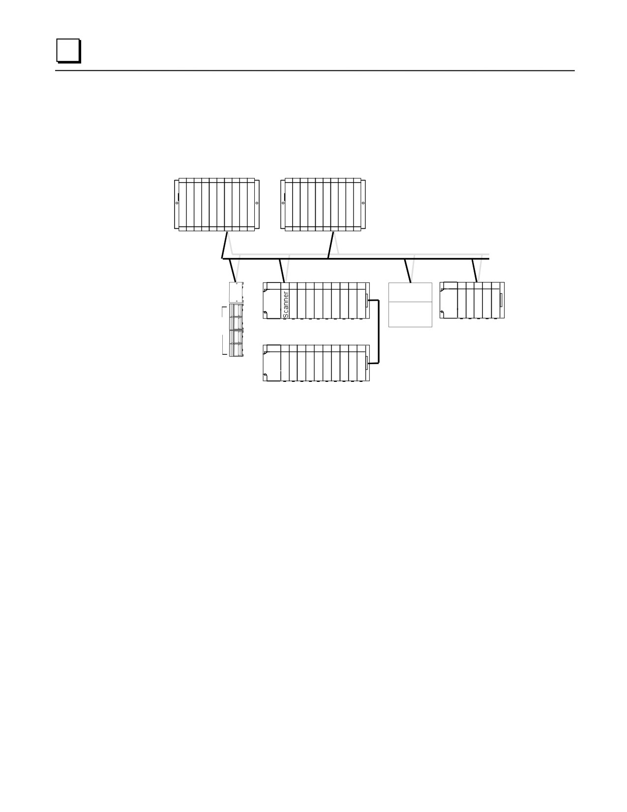
Figure 8-6. Example of FIP I/O System Configuration
A FIP bus is used primarily for I/O control. It also is used to store configuration data to remote
devices and to report faults. Devices that can be on a FIP bus in a Series 90-30 PLC system
include:
Series 90-70 PLC, interfaced to a FIP bus by a FIP Bus Controller.
Field Control Stations, Field Control I/O modules that are interfaced to the bus via a FIP Bus
Interface Unit (BIU).
Remote Drops, Series 90-30 I/O racks that are interfaced to the bus via FIP Remote I/O
Scanner Modules. Each remote drop can include one 5- or 10-slot main rack, one 5- or 10-slot
expansion rack and any mix of discrete and analog I/O modules.
Generic Devices, such as general-purpose computers that are interfaced to the bus via a FIP
Interface Module.
8-10
Series 90-30 PLC Installation and Hardware Manual - August 2002
GFK-0356Q
8
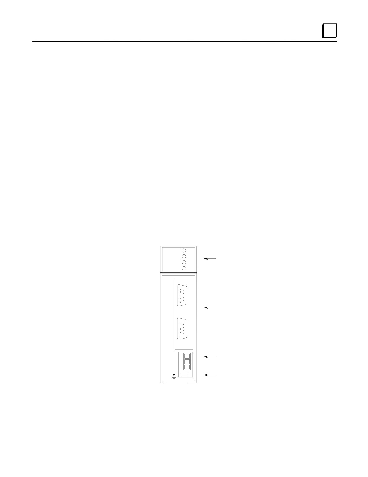
The FIP Bus Controller is a standard, rack-mounted Series 90-30 PLC module. It plugs easily into
the PLC’s backplane. The latch on the bottom of the module secures it in position.
Module OK
Run
Carrier Detect Ch. 1
Transmit Enable Ch. 1
Carrier Detect Ch. 2
Transmit Enable Ch. 2
15-Pin Serial Connector RS-485
9-Pin FIP Fieldbus Connector
(channel 1)
9-Pin FIP Fieldbus Connector
(channel 2)
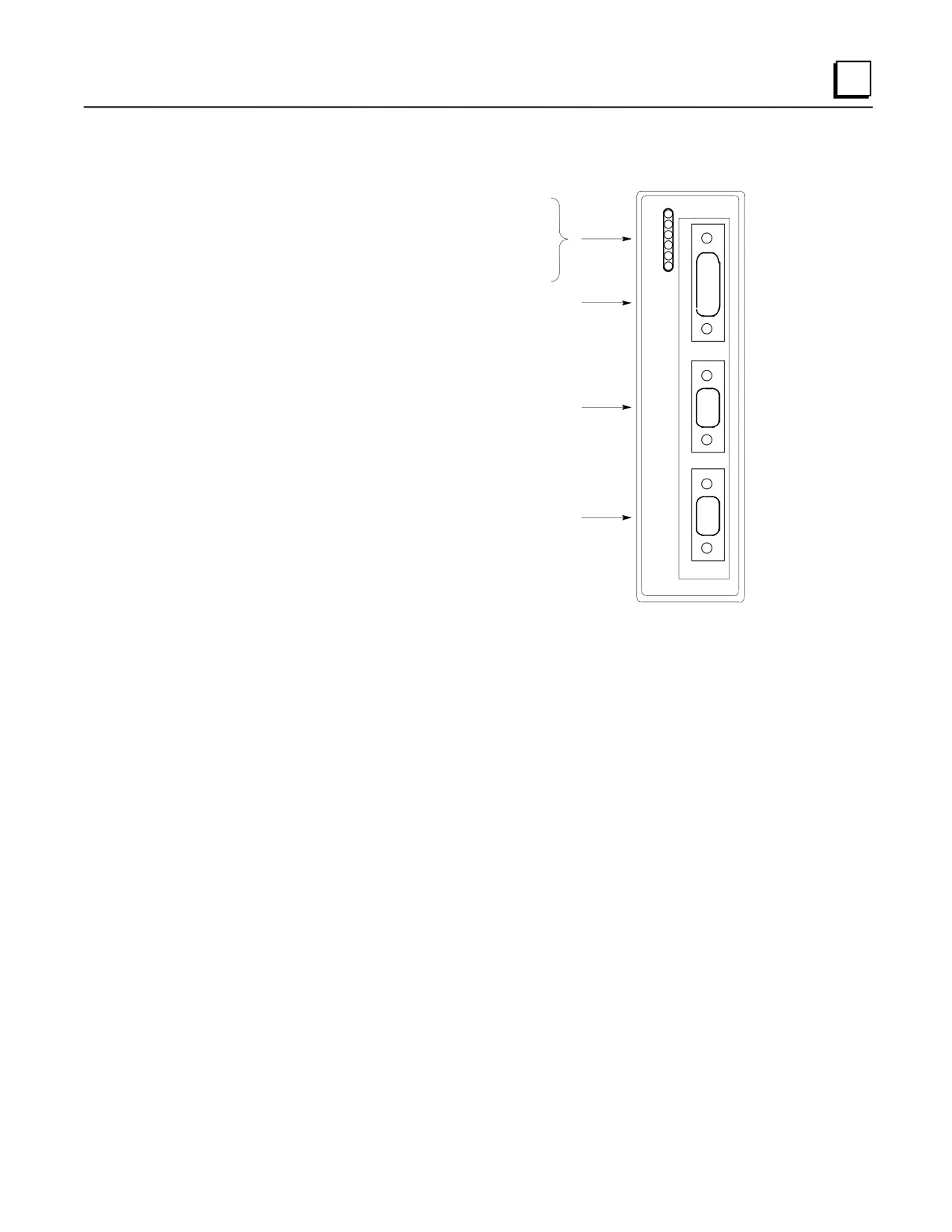
Figure 8-7. Series 90-30 FIP Bus Controller
There are no DIP switches or jumpers to set on the module.
The Series 90-30 FIP Bus Controller has six status LEDs, an RS-485 serial port, and two identical
FIP bus connectors.
Status LEDs
The 6 LEDs on the front of the FIP Bus Controller display module status and communications
activity.
Serial Port
The 15-pin serial port is used to connect a computer for upgrading the operating firmware of the
Bus Controller and for configuring by an external configuration tool.
FIP Bus Connectors
The two 9-pin connectors on the FIP Bus Controller provide for attachment of one or two FIP
busses. The two busses provide a redundant bus capability.
GFK-0356Q
Chapter 8 Option Modules
8-11
8
IC693BEM330 FIP Remote I/O Scanner Module
The FIP (Factory Instrumentation Protocol) Remote I/O Scanner (catalog number IC693BEM330)
is an intelligent module that interfaces Series 90-30 I/O modules to a FIP bus. Up to 19 I/O
modules can be accommodated by using two 10-slot baseplates connected by an expansion cable.
Together, the Remote I/O Scanner and the modules it serves are referred to as an I/O Nest. The FIP
Nest can include most Series 90-30 I/O modules.
The host CPU can be any type of CPU capable of communicating on a FIP bus. A module in the
host (such as a FIP Bus Controller) provides the necessary interface between the FIP bus and the
host CPU.
Hand-held
Programmer
Host CPU
I/O Nest
CPU
FIP
Bus
Controller
FIP Bus
Expansion Cable,
up to 50 feet (15 Meters)
Up to 128 devices
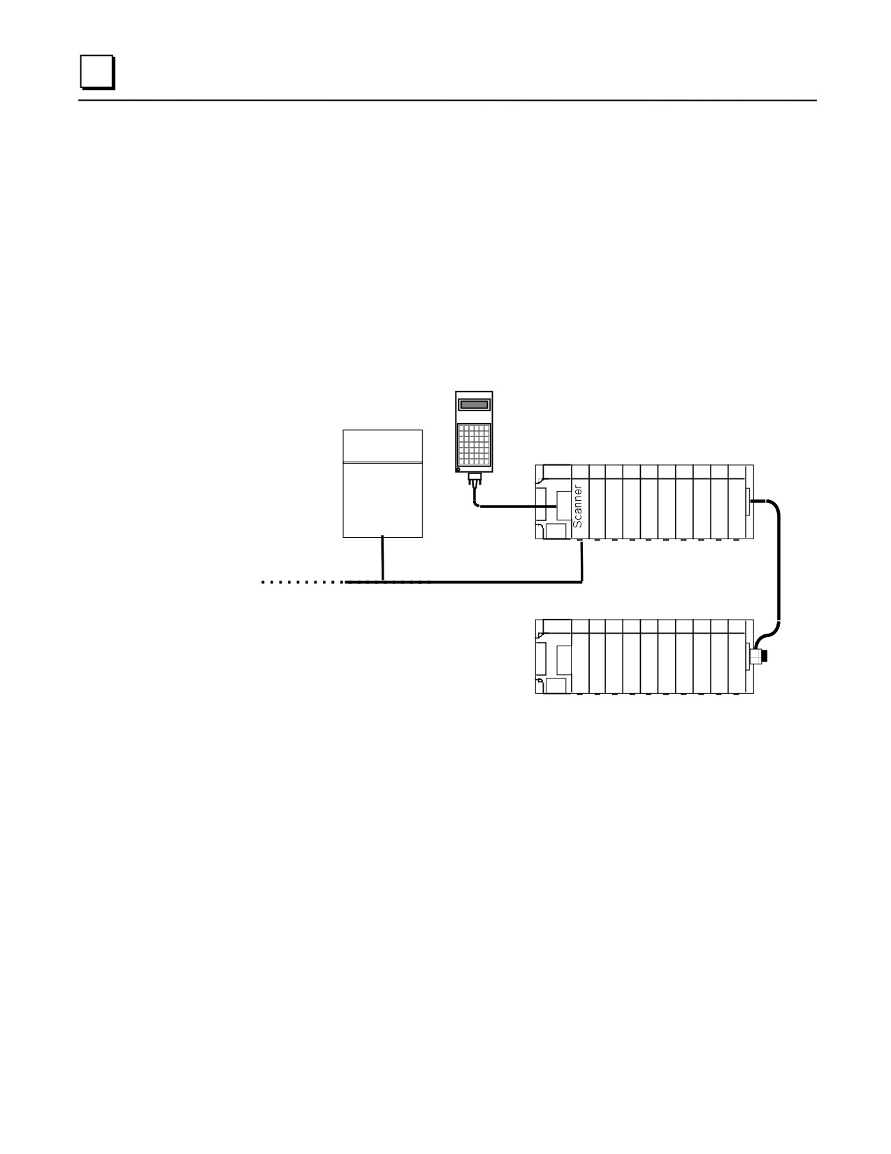
Figure 8-8. Example of FIP Remote I/O Scanner System Configuration
The Series 90-30 Hand-Held Programmer provides a convenient way to perform setup, monitoring,
and control functions.
Features of the Remote I/O Scanner
The FIP Remote I/O Scanner performs the following basic functions:
controls operation of the I/O nest in the selected mode
scans discrete and analog I/O modules and maintains I/O scan timing
maps I/O data to FIP application variables
detects module and system faults and reports them to the FIP network
permits standalone configuration using Hand-Held Programmer
retains its network configuration through loss of power
8-12
Series 90-30 PLC Installation and Hardware Manual - August 2002
GFK-0356Q
8
permits I/O forcing from the Hand-Held Programmer
detects and records input transitions
supports FIP messaging services
responds to an external synchronization signal
can provide blinking or pulsed outputs
can provide input filtering and chatter detection
FIP Bus Interface
The Remote I/O Scanner communicates at a data rate of 1MHz. There are two versions of the FIP
communications standard: FIP and WORLD FIP. A DIP switch on the module is used to select the
version that will be used by the Remote I/O Scanner. (The same communications method will then
be used on both bus cables).
The DIP switch on the module must be set to the FIP position for the Remote I/O Scanner to
communicate with a Series 90-70 PLC.
Module Description
The FIP Remote I/O Scanner is a standard Series 90-30 PLC module that plugs easily into the
backplane of the baseplate.
FIP CH S2
CD1
1.0 MHz
TEN1
LEDs
CD2
TEN2
C
H
A
N
N
E
L
1
FIP Bus Connectors
C
H
A
N
N
E
L
2
S
Y
Synchro Connector
N
C
H
R
O
Lug for Ground Wire
Figure 8-9. FIP Bus Interface Module
GFK-0356Q
Chapter 8 Option Modules
8-13
8
Connectors
The front of the module has the following connectors:
CHANNEL 1
9-pin male D connectors for two FIP bus cables. A bus can be disconnected
CHANNEL2
from the module without disturbing the continuity of the bus. The second bus is
a backup for the first bus; its use is optional.
SYNCHRO
Connector for a FIP synchronization cable. It requires a mating connector such
as Molex #39-01-4031. The synchronization capability is not used in a Series
90-70 PLC application.
(ground)
The lug below the Synchro connector is used for the module ground wire
(provided). The other end of the ground wire must be connected to the mounting
bolt on the lower left corner of the baseplate and to chassis ground.
LEDs
There are two pairs of LEDs at the top of the module. The upper pair is for channel 1 and the lower
pair is for channel 2.
CD1/CD2
The green Carrier Detected LEDs indicate the presence of a carrier-detect signal
on their respective channels.
TEN1/TEN2
The red Transmission Enabled LEDs indicate the module is generating
transmissions on their respective channels.
FIP Remote I/O Scanner Documentation:
GFK-1037, Series 90-30 FIP Remote I/O Scanner User’s Manual
GFK-1038, FIP Bus Controller User’s Manual
8-14
Series 90-30 PLC Installation and Hardware Manual - August 2002
GFK-0356Q
8
IC693APU301/302 Motion Mate Axis Positioning Module (APM)
The Motion Mate APM is an easy-to-use intelligent, fully programmable one-axis (IC693APU301)
or two-axis (IC693APU302) motion control module for the Series 90-30 PLC. The APM allows a
PLC user to combine high-performance control with PLC logic solving functions in one integrated
system. The APM can be configured to operate in either Standard mode or Follower mode. When
used in Standard mode, it combines high-performance motion control with PLC logic solving
functions in one integrated system. When used in Follower mode, it provides high-performance
“electronic gearing” for continuous master/slave applications. The desired mode is easily selected
by configuring a setup parameter in the configuration software.
EN1
STAT
EN2
OK
CFG
AXIS POS
MODULE
ONE
AXIS
C
O
M
M
B
A
Figure 8-10. Motion Mate APM Module
The Series 90-30 and APM operate together as one integrated motion control package. The APM
controls axis motion and handles all direct communications to the drive and machine while the
PLC automatically transfers data between PLC tables and the APM.
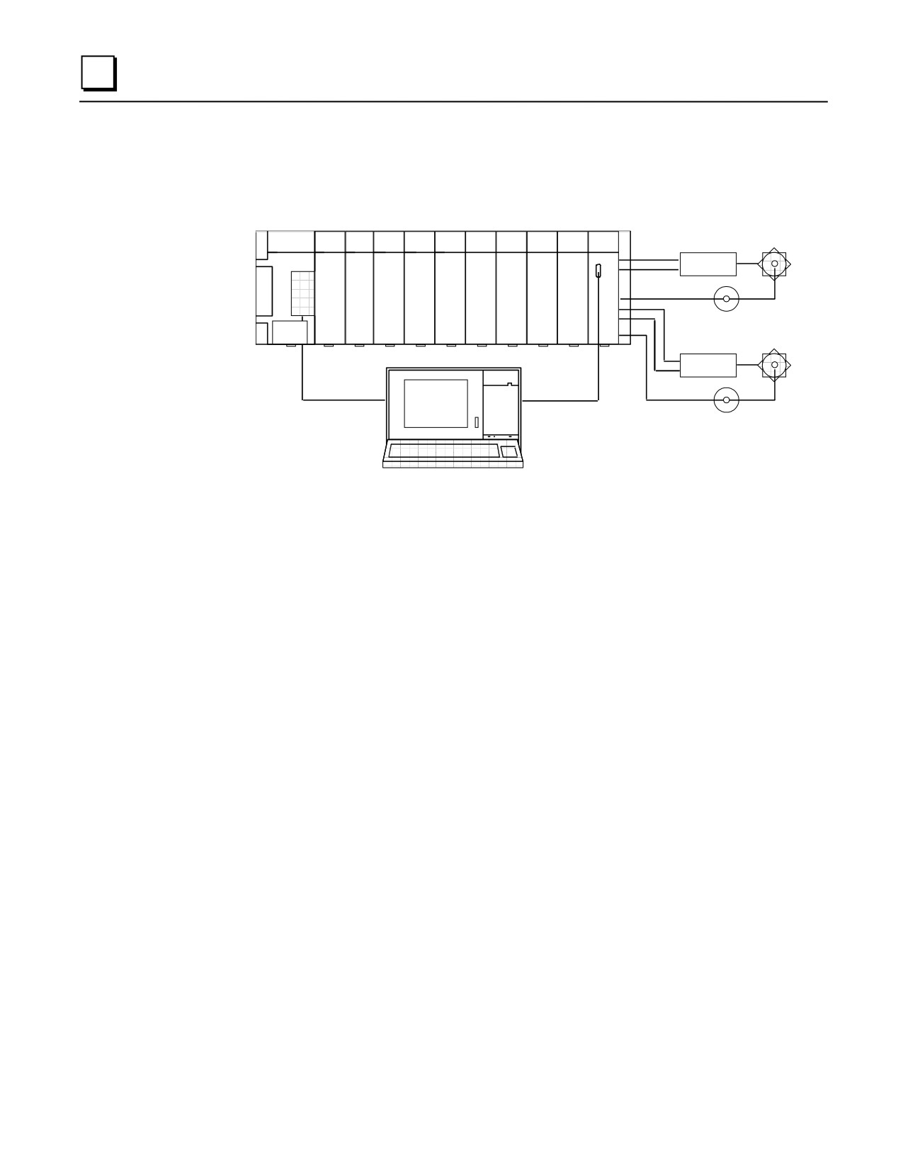
The PLC also provides a means for connecting Operator Interfaces, which can control and monitor
system operation. An example of an APM servo system showing the hardware and software used
to configure, program, and operate the system is shown below.
The APM can be installed in any Series 90-30 CPU, expansion, or remote baseplate. For
embedded CPUs (311, 313, or 323), you may have up to three APM modules. For a modular CPU
(331 or higher), you may have up to eight APM modules in one system, with a maximum of three
APM modules per baseplate.
Multiple motion programs may be created and stored in the APM (maximum of 10 may be stored
in the APM) with the Motion Programmer software package. The APM is configured and
programmed with VersaPro software (Version 1.1 or later) or Logic Developer-PLC.
GFK-0356Q
Chapter 8 Option Modules
8-15
8
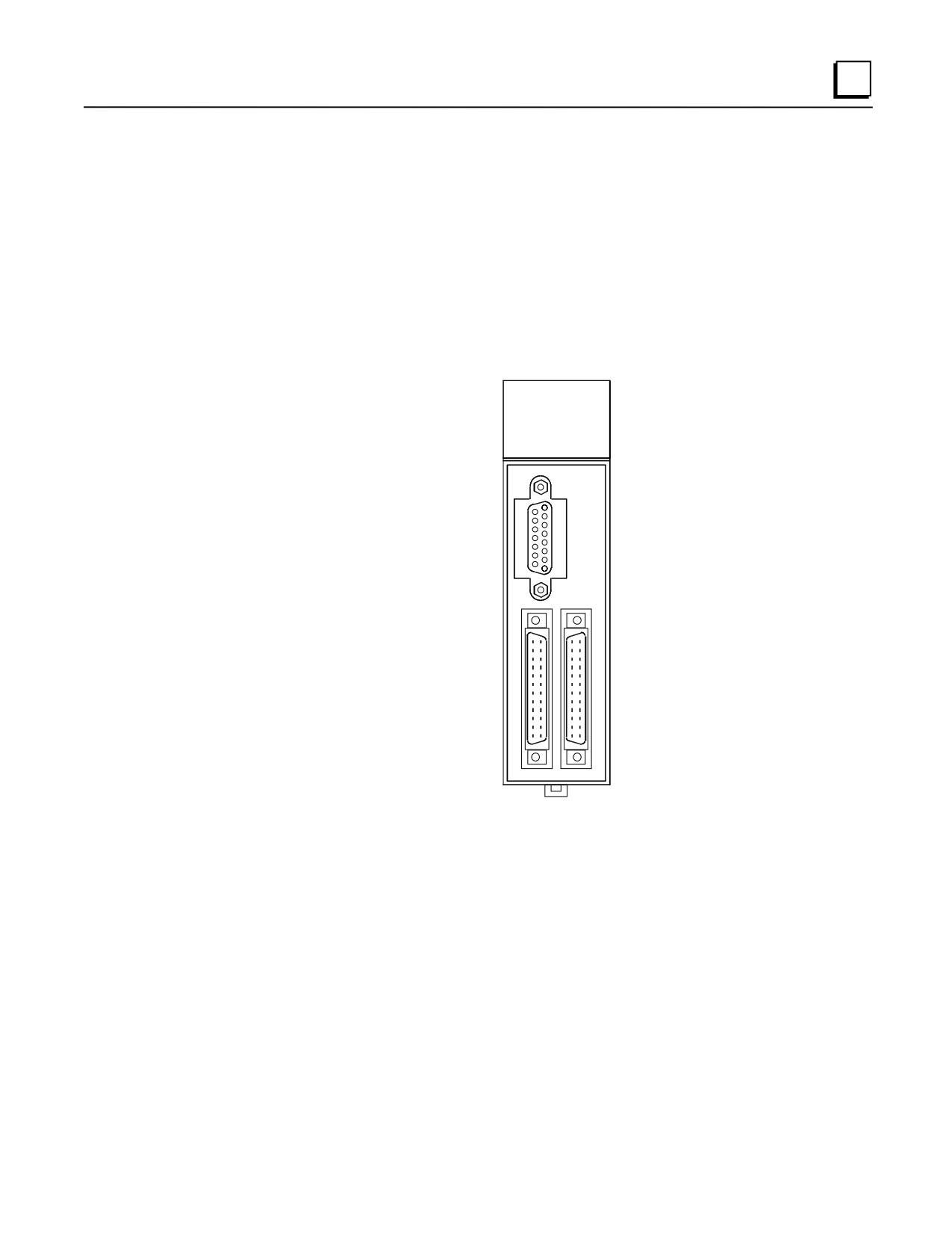
The APM faceplate (front panel) has two 24-pin high-density connectors for servo connections.
The connector labeled A contains connections for Axis 1. Connector B, for a 1-axis APM, contains
general purpose connections. Connector B, for a 2-axis APM, has connections for Axis 2 as well
general purpose connections. To make wiring easier to the drive and machine, each high-density
connector is typically connected by a short cable to a terminal block.
CPU
APM
MACHINE 1
DRIVE
ENCODER 1
MACHINE 2
DRIVE
Motion Programming
Configuration Software
Software
ENCODER 2
Figure 8-11. Example of Motion Mate APM Servo System
APM Cables
These cables consists of a 24-pin I/O connector , a cable, and a 25-pin D-type terminal block
connector. (Cables are documented in Chapter 10.) Available cables are:
IC693CBL311 (10 feet/3 meters)
IC693CBL319 (3 feet/1 meter)
IC693CBL317 (10 feet/3 meters) with an 8” external shield pigtail
C693CBL320 (3 feet/1 meter) with an 8” external shield pigtail
For building custom-length cables, the 24-pin I/O cable connector is available in three different kits
(solder eyelet receptacle, crimp wire receptacle, and IDC (ribbon) receptacle). The terminal block
is Weidmuller RD25 910648 or equivalent (must be compatible with the I/O cable
IC693CBL311/319/317/320 - see Chapter 10 for details).
Motion Mate APM Module Documentation
See the following manuals for detailed information on Power Mate APM Modules:
GFK-0840
Motion Mate APM for Series 90-30 PLC Standard Mode User’s Manual
GFK-0781
Motion Mate APM for Series 90-30 PLC Follower Mode User’s Manual
GFK-0664
Series 90 PLC APM Programmer’s Manual
Related servo manual:
GFK-1581 SL Series Servo User’s Manual
8-16
Series 90-30 PLC Installation and Hardware Manual - August 2002
GFK-0356Q
8
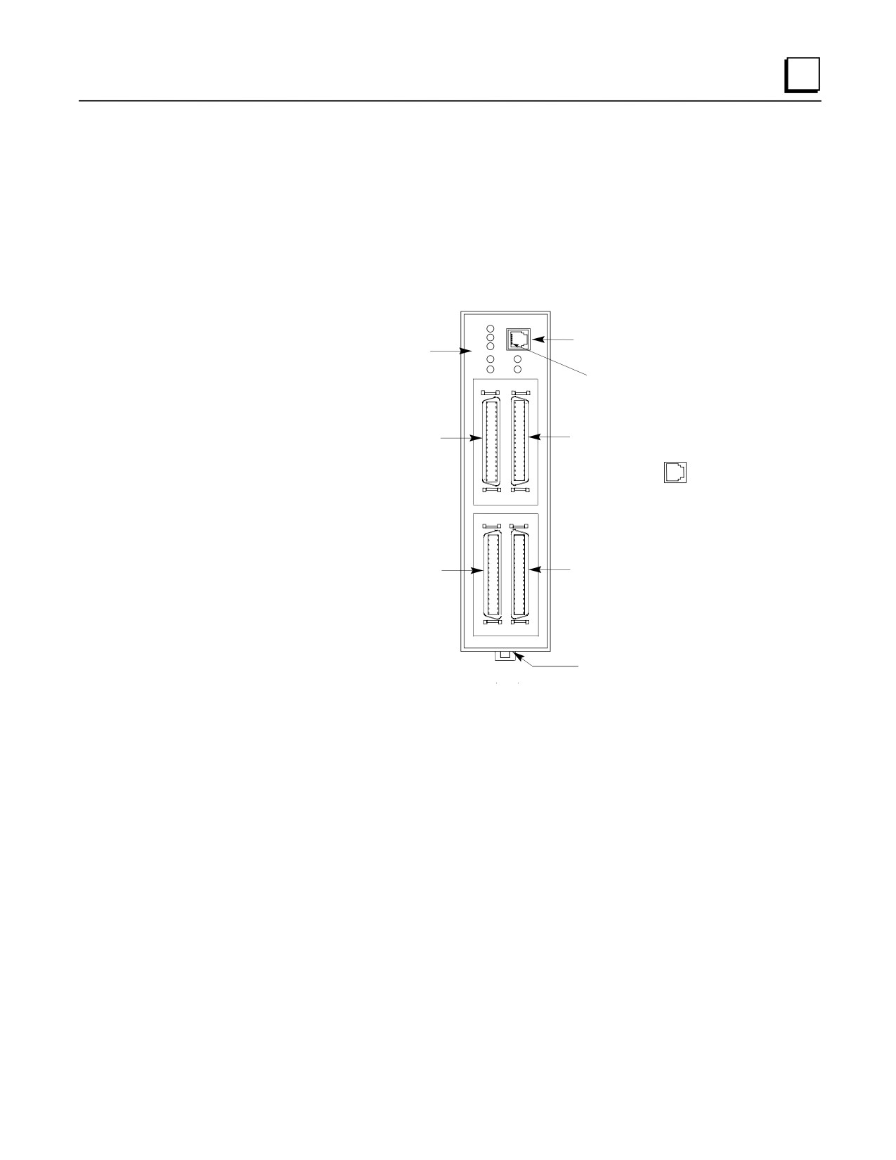
IC693DSM302 Motion Mate Digital Servo Module (DSM302)
The Motion Mate DSM302 is a high-performance, two-axis motion control module that is highly
integrated with the logic solving and communications functions of the Series 90-30 PLC. In digital
mode, this module controls GE Fanuc digital servos. Beginning with firmware version 1.40, this
module has the ability to control servos with an analog command input, such as the GE Fanuc SL
Series Servos, or third party analog servos.
Status LEDs
COMM
COMM
STAT
STAT
OK
6-pin, RJ-11 connector
OK
CFG
used to upgrade firmware
CFG
EN3
EN1
and load motion programs
EN1 - EN4
EN4
EN2
(use cable IC693CBL316)
C
A
Pin 1
Connector C
Connector A
Aux Axis 3
Servo Axis 1
(Follower Master Axis)
PORT 1
RS-232
D
B
Connector D
Connector B
Aux Axis 4
Servo Axis 2
Motion Mate DSM302
Grounding Tab
Figure 8-12. Motion Mate DSM302 Module
GFK-0356Q
Chapter 8 Option Modules
8-17
8
Features.
Digital Signal Processor (DSP) control of GE Fanuc Servos
Block Processing time under 5 milliseconds
Velocity Feed forward and Position Error Integrator to enhance tracking accuracy
High resolution of programming units
- Position:
-8,388,608...+8,388,607 User Units
- Velocity:
1 ... 8,388,607 User Units/sec
- Acceleration:
1 .. 134,217,727 User Units/sec/sec
Simple and powerful Motion Program instruction set
Simple 1- or 2-axis motion programs with synchronized block start
Program support for a short motion program, called Program 0, which can be created in the
configuration software
Non-volatile storage for 10 programs and 40 subroutines, created with the APM Motion
Programming software.
User scaling of programming units (User Units)
DSM firmware, stored in Flash memory, is updated via its front panel COMM port.
Generic programming using command parameters as operands for Acceleration, Velocity,
Move, and Dwell Commands
Automatic Data Transfer between PLC tables and DSM302 without user programming
Ease of I/O connection with factory cables and terminal blocks as well as a serial port for
connecting programming devices. The serial port also allows ”soft“ upgrades to firmware,
which is stored in Flash memory.
Control of GE Fanuc Digital servos, analog SL Series Servos, or third party analog servos.
Home and overtravel switch inputs for each Servo Axis
Two Position Capture Strobe Inputs for each Position Feedback Input
5v , 24v and analog I/O for use by PLC
A Quad B Encoder input for Follower Master axis
13 bit Analog Output can be controlled by PLC or used as Servo Tuning monitor
IC693DSM302 Documentation
GFK-1464, Motion Mate DSM302 for Series 90-30PLCs User’s Manual.
GFK-0664, Series 90-30 PLC APM Programmer’s Manual
Related servo manuals:
GFK-1581, SL Series Servo User’s Manual
8-18
Series 90-30 PLC Installation and Hardware Manual - August 2002
GFK-0356Q
8
GFH-001, Beta Series Servo Products Specification Guide
GFZ-65192EN, Alpha Series Servo Amplifier (SVU) Descriptions Manual
GFZ-65162E, Control Motor Amplifier, Alpha Series
GFZ-65142E, GFZ-65150E, GFZ-65165E, Alpha Series Servo Motor Manuals
GFK-0356Q
Chapter 8 Option Modules
8-19
8
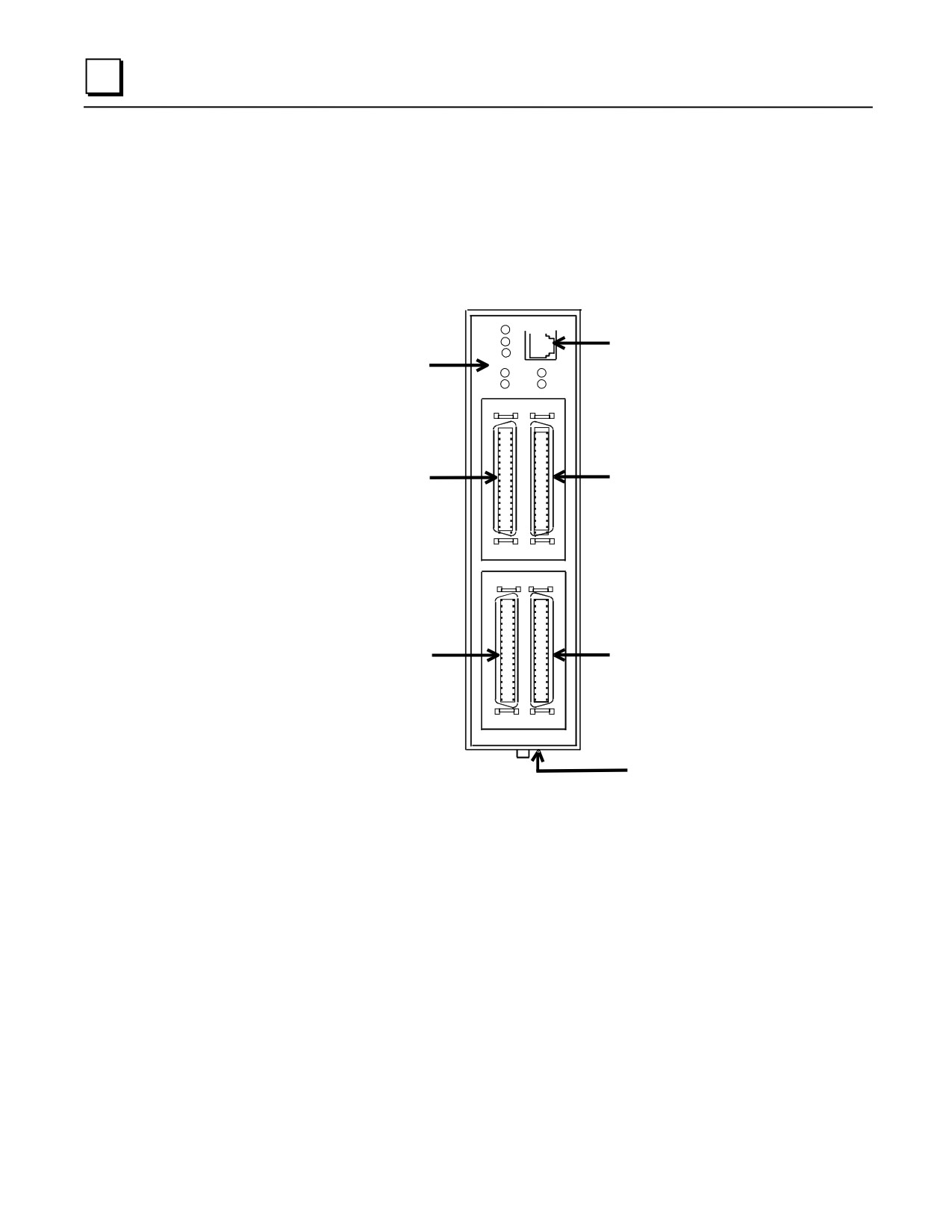
IC693DSM314 Motion Mate Digital Servo Module (DSM314)
The Motion Mate DSM314 is a high-performance motion control module that is highly integrated
with the logic solving and communications functions of the Series 90-30 PLC. In digital mode, this
module controls GE Fanuc digital servos. In analog mode, this module controls servos with an
analog command input, such as the GE Fanuc SL Series Servos, or third party analog servos.
COMM
Status LED’s
COMM
6-pin RJ-11 connector.
STAT
Stat
OK
Provides RS-232
CFG
connection for firmware
OK
EN3
EN1
update
CFG
EN4
EN2
EN1 - EN4
C
A
Connector C
Connector A
Servo Axis 3
Servo Axis 1
D
B
Connector D
Connector B
Servo Axis 4
Servo Axis 2
Motion Mate
DSM314
Grounding Tab on
Bottom of Module
Figure 8-13. Motion Mate DSM314 Module
8-20
Series 90-30 PLC Installation and Hardware Manual - August 2002
GFK-0356Q
8
Features
Digital Signal Processor (DSP) control of GE Fanuc Servos
Block Processing time under 5 milliseconds
Velocity Feed Forward and Position Error Integrator to enhance tracking accuracy
High resolution of programming units
- Position:
-536,870,912...+536,870,911 User Units
- Velocity:
1 ... 8,388,607 User Units/sec
- Acceleration:
1 … 1,073,741,823 User Units/sec/sec
Simple and powerful motion program instruction set
Simple 1- to 4-axis motion programs. Multi-axis programs using Axes 1 and 2 may utilize a
synchronized block start.
Non-volatile storage for 10 programs and 40 subroutines created with VersaPro software
(Version 1.1 or later).
Compatible with Series 90-30 CPUs equipped with firmware release 10.0 or later (will not
work with CPUs 311 - 341 and 351).
Single point of connection for all programming and configuration tasks, including motion
program creation (Motion Programs 1 - 10) and Local Logic programming. All programming
and configuration is loaded through the PLC’s programming communications port. In turn, the
CPU loads all configuration, motion programs, and Local Logic programs to the DSM314
across the PLC backplane.
User scaling of programming units (User Units) in both Standard and Follower modes.
DSM314 firmware, stored in Flash memory, is updated via its front panel COMM port.
Firmware update kits provide firmware and Loader software on floppy disk. Firmware is also
Recipe programming using command parameters as operands for Acceleration, Velocity,
Move, and Dwell Commands
Automatic Data Transfer between PLC tables and DSM314 without user programming
Ease of I/O connection with factory cables and terminal blocks
Electronic CAM capability, starting with Firmware Release (Version) 2.0
Control of GE Fanuc α Series and β Series Digital servos, SL-Series servos, or third party
servos with analog velocity command or analog torque command interface.
Home and overtravel switch inputs for each Servo Axis
Two Position Capture Strobe Inputs for each axis can capture axis and/or master position with
an accuracy of +/-2 counts plus 10 microseconds of variance.
5V , 24V and analog I/O for use by PLC
Incremental Quadrature Encoder input on each axis for Encoder/Analog mode
Quadrature Encoder input for Follower Master axis
13 bit Analog Output can be controlled by PLC or used as Digital Servo Tuning monitor
High speed digital output (four each 24V and four each 5V) via on-board Local Logic control
GFK-0356Q
Chapter 8 Option Modules
8-21
8
IC693DSM314 Documentation
GFK-1742, Motion Mate DSM314 for Series 90-30 PLC User’s Manual
Related servo manuals:
GFK-1581, SL Series Servo User’s Manual
GFH-001, Beta Series Servo Products Specification Guide
GFZ-65192EN, Alpha Series Servo Amplifier (SVU) Descriptions Manual
GFZ-65162E, Control Motor Amplifier, Alpha Series
GFZ-65142E, GFZ-65150E, GFZ-65165E, Alpha Series Servo Motor Manuals
8-22
Series 90-30 PLC Installation and Hardware Manual - August 2002
GFK-0356Q
8
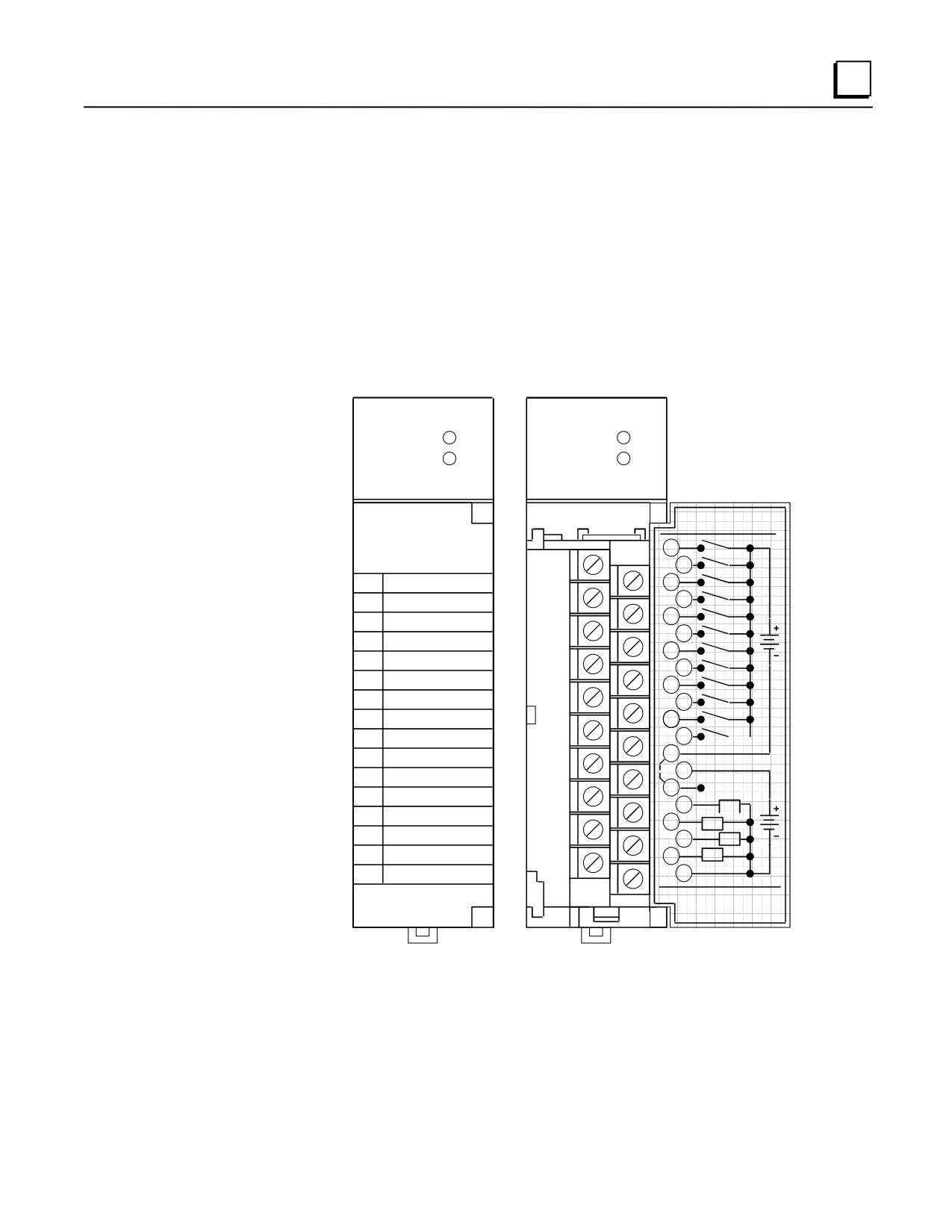
IC693APU300 High Speed Counter (HSC) Module
The High Speed Counter (IC693APU300) for the Series 90-30 PLC is a single-slot module which
can be used in applications where pulse input rates exceed the input capability of the PLC or where
too large a percentage of PLC processing capability would be required. The High Speed Counter
provides direct processing of rapid pulse signals up to 80 KHz for industrial applications such as:
meter proving, turbine flowmeter, velocity measurement, material handling, motion control and
process control.
With direct processing, the High Speed Counter module is able to sense inputs, count, and respond
with outputs without needing to communicate with a CPU. It can be configured to count either up
or down, to count both up and down, or to count the difference between two changing values. The
module can be configured to provide 1, 2, or 4 counters of differing complexity.
a43971A
HIGH
HIGH
SPEED
SPEED
COUNTER
OK
COUNTER
OK
CFG
CFG
HIGH SPEED
HIGH SPEED
5/12/24
COUNTER
I1
1
5/12/24 VDC
I2
2
I3
I1
3
I4
4
I2
I5
5
I3
I6
6
I4
I7
7
I5
I8
8
I6
I9
9
I7
10
I10
I11
I8
11
12
I12
I9
13
I10
14
I11
15
5V OPTION
I12
16
01
O1
17
02
O2
18
03
O3
19
04
O4
20
44A729182-
SLOT
FOR USE
IC693APU30
Figure 8-14. High Speed Counter (HSC)
The High Speed Counter can be installed in any Series 90-30 baseplate and is configured using the
Hand-Held Programmer, Logicmaster 90-30/20, VersaPro software, or Logic Developer-PLC.
Many features can also be configured from the user’s application program. There are no jumpers to
be set on the module. Two LEDs at the top of the module indicate the operating status of the
module and the status of configuration parameters.
For details on the HSC, refer toGFK-0293, Series 90-30 High Speed Counter User’s Manual.
GFK-0356Q
Chapter 8 Option Modules
8-23
8
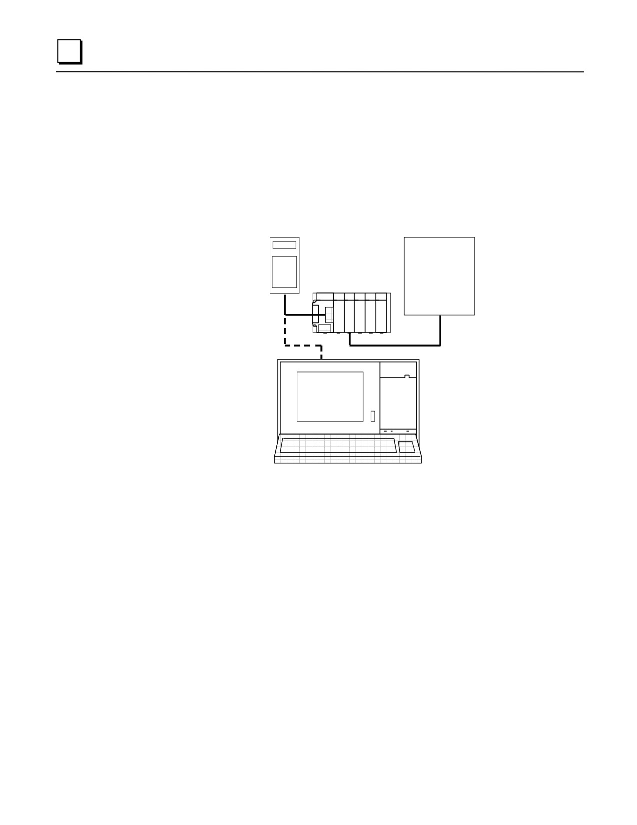
IC693BEM320 I/O LINK Interface (Slave) Module
The I/O LINK Interface module (IC693BEM320) provides an interface between a Series 90-30
PLC and a proprietary Fanuc I/O LINK in a Fanuc CNC (Computer Numerical Control), or a
Series 90-70 PLC. This module is configured as a slave device only (see the IC693BEM321 for
master applications). The Fanuc I/O LINK is a serial interface which provides high speed
exchange of data between a master and up to 16 slaves. An example of a Series 90-30 PLC in a
Fanuc I/O LINK system configuration is shown in the following illustration.
HHP
MASTER
SERIES 90-30
I/O LINK
PROGRAMMER
Figure 8-15. Example of a Series 90-30 PLC in a Fanuc I/O LINK Configuration
The Series 90-30 I/O LINK Interface module is configured as a slave device only and allows the
Series 90-30 PLC to send either 32 or 64 I/O points to the I/O LINK. The I/O LINK module must
be configured as either a 32 or 64 point I/O module during installation by setting a jumper plug
inside of the front cover of the module to either 32 I/O or 64 I/O.
An I/O LINK Interface module can be installed in any model of Series 90-30 PLC, and any
number of I/O LINK Interface modules can be installed in a system within the current limits of the
baseplate and other I/O modules installed in the baseplate. For more details, see ”Load
Requirements for Hardware Components” in Chapter 12 of this manual.
I/O Link Interface Documentation
For detailed information on this module, refer to GFK-0631, the Series 90-30 I/O LINK Interface
Module User’s Manual.
8-24
Series 90-30 PLC Installation and Hardware Manual - August 2002
GFK-0356Q
8
IC693BEM321 I/O LINK Master Module
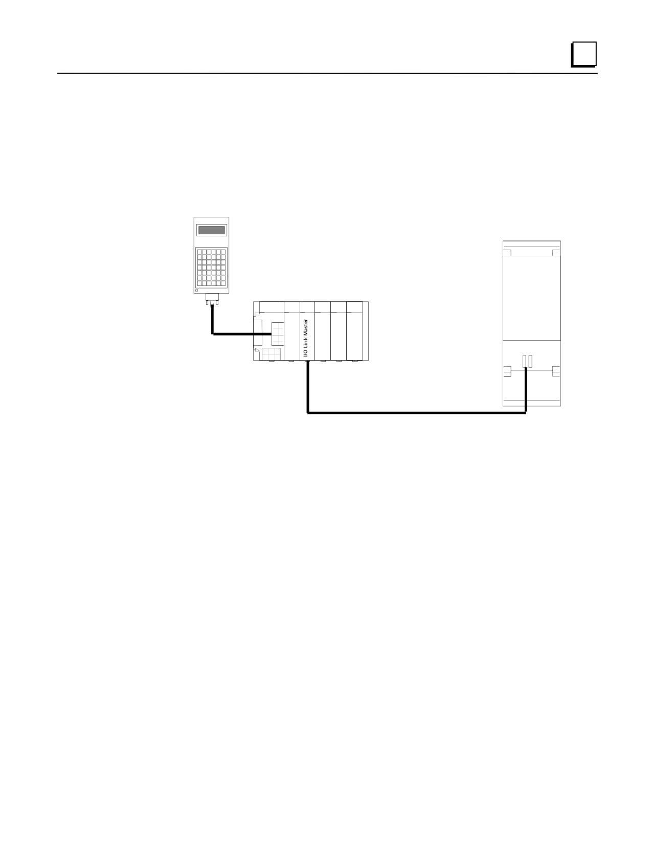
The Series 90-30 I/O LINK Master Module (IC693BEM321) allows a Series 90-30 PLC to act as a
master on a proprietary Fanuc I/O LINK. The Fanuc I/O LINK is a serial interface which provides
high-speed exchange of I/O data between the master and up to 16 slaves. The master can receive
1024 discrete inputs from slaves, and send up to 1024 discrete outputs.
HHP
Power Mate CNC
Master
Series 90-30 PLC
I/O LINK
Figure 8-16. Example of I/O LINK Master System Configuration
The illustration above shows a simple I/O LINK system: a Series 90-30 PLC used as a master, a
Series 90-30 Hand-held Programmer, an I/O LINK, and one slave. In the illustration, the slave is a
Power Mate CNC. Other devices that can be used as slaves include the Series 90-70 PLC, the
Series 90-30 PLC, the Fanuc Series 0 CNC, Fanuc Connection Units, and Fanuc Operator Panels.
The module can be configured using a Series 90-30 Hand-held Programmer (HHP) or the
configuration software.
GFK-0356Q
Chapter 8 Option Modules
8-25
8
Any number of I/O LINK Master Modules can be installed in a Series 90-30 PLC. When there are
multiple I/O LINK Master Modules in the same PLC, they must be on separate I/O LINKs. An I/O
LINK Master Module can be installed in any I/O slot in any baseplate. The maximum number of
I/O LINK Master Modules that can be installed in the CPU baseplate is six,
Restart Pushbutton
The LINK RESTART pushbutton provides a convenient means of restart if a failure occurs.
Pushing the Restart pushbutton restarts the operation of the LINK.
Serial Port
The front of the module has one 20-pin, Honda-type connector, used for connection to the first
slave on the I/O LINK. Signal levels are RS422/485 compatible.
Compatibility
The Series 90-30 I/O LINK Master Module is compatible with the following devices:
Host CPU
Series 90-30 CPU models 311, 313, 321, 323, 331, and 341 release 4.4 or later, and all
versions of the CPU models 350, 351, 352, 360, 363, and 364.
Series 90-30 Hand-held Programmer (HHP)
Programmer
Hand-Held Programmer
Logicmaster 90-30 Programming Software Configurator, release 4.5 or later.
VersaPro Software.
Control programming software, Version 2.0 or later.
Logic Developer-PLC software
Slave Units
Power Mate models A, C, D, and E
Series 0 CNC
Fanuc Operator Panel Unit
Fanuc Connection Unit 1
Fanuc Connection Unit 2
Series 90-30 PLC with 90-30 I/O LINK Slave Module
Series 90-70 PLCs with 90-70 I/O LINK Interface Module set up as slave
I/O Link Master Module Documentation
For detailed information on this module, refer to GFK-0823, the Series 90-30 I/O LINK Master
Module User’s Manual,
8-26
Series 90-30 PLC Installation and Hardware Manual - August 2002
GFK-0356Q
8
IC693APU305 I/O Processor Module
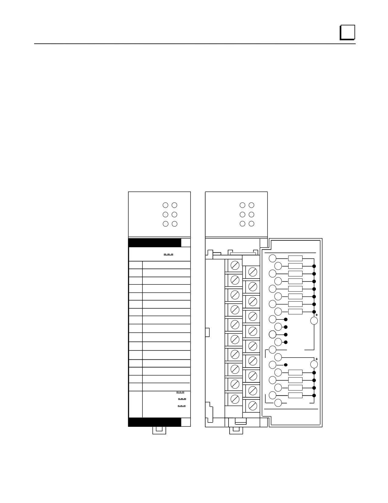
The I/O Processor (IOP) module (IC693APU305) for the Series 90-30 PLC provides direct
processing of rapid pulse signals for industrial control applications such as:
Fast response process control
Velocity measurement
Material handling, marking, and packaging
Direct processing means that the module is able to sense inputs, process the input information, and
control the outputs without needing to communicate with a CPU.
During each CPU sweep, the I/O Processor communicates with the CPU through 32 discrete inputs
(%I), 15 words of analog inputs (%AI), 32 discrete outputs (%Q), and 6 words of analog outputs
(%AQ). The %AQ outputs can be used by the CPU program to set up timer values or send other
controlling parameters to the I/O Processor.
a45380
I/O
I/O
PROC
1
2
PROC
1
2
MODULE
MODULE
3
4
3
4
CFG
OK
CFG
OK
I/O PROCESSOR
5/12/24 VDC
I/O PROCESSOR
5/12/24 VDC
1
IN1
IN1
2
IN2
IN2
3
IN3
IN3
4
IN4
IN4
5
IN5
IN5
6
IN6
IN6
7
IN7
IN7
8
IN8
IN8
9
IN9/OUT5
V
I9/
10
IN10/OUT6
05
I10/
11
IN11/OUT7
06
12
IN12/OUT8
I11/
07
13
INCOM
I12/
08
14
I
OUT1
N
15
SHIELD
V
OUT2
T
E
16
OUT1
OUT3
R
17
OUT2
N
OUT4
A
18
OUT3
L
OUT
1-8:
0.02A @ 5
19
OUT4
OUT
1-4:
1.0A @ 12/24
20
OUTCOM
OUT
5-8:
0.5A @ 12/24
4.0A/MODUL
44A729182-070R01
FOR USE WITH
IC693APU305
Figure 8-17. I/O Processor Module
GFK-0356Q
Chapter 8 Option Modules
8-27
8
The I/O Processor is configured using the Series 90-30 Hand-held Programmer, Logicmaster
90-30, VersaPro, or Logic Developer-PLC software. Many configuration parameters can be
modified from the user’s application program as well. Each configuration parameter is set to a
factory default value which is suitable for many applications. There are no jumpers or DIP
switches to set on the module. Six green LEDs at the top of the module indicate the operating
status of the module, the status of configuration parameters, and the state of hardware outputs 1
through 4.
Module Features
Module features include:
Up to 12 positive logic (source) inputs with input voltage range selection of either 5 VDC
(TTL) or 10 to 30 VDC (non-TTL).
Up to eight positive logic (source) outputs: four outputs with 1 amp rating and four
configurable outputs with 0.5 amp rating
Outputs protected by replaceable fuse (one fuse common to all outputs)
Dedicated processor provides 500 ∝s I/O update
Counts per Timebase register for input rate measurement
Total Counts register (32-bit) accumulates total counts received by module
Four Strobe data registers for input position capture
Two Timer data registers for indicating input pulse length or input spacing in milliseconds
Thirty-two range comparators (outputs returned in %I and %AI data)
Software configuration
Internal module diagnostics
Individual LEDs that indicate Module OK and Configured OK status
Individual LEDs that indicate state of Outputs 1 through 4
A removable terminal board for connection of field wiring.
Inputs can be used as count signals or edge-sensitive strobe signals. Outputs can be used to drive
indicating lights, solenoids, relays, and other devices.
Power to operate the module’s logic circuitry is obtained from the 5 VDC bus on the baseplate
backplane. Power sources for the input and output devices must be supplied by the user or by the
+24 VDC isolated output of the Series 90-30 power supply. The I/O Processor module provides a
selectable threshold voltage to allow the inputs to respond to either a 5 VDC signal level or a 10 to
30 VDC signal level. The threshold is selected by configuration.
All configuration parameters for the module are downloaded from the PLC to the I/O Processor
after it passes its internal diagnostics. Once the module has been successfully configured, the
CONFIG OK LED will turn on. Configuration parameters can be changed using the
programming/configuration software or the Hand-Held Programmer.
Operation of the I/O Processor module is monitored by a watchdog timer circuit. If the watchdog
timer detects a module failure, it will force all outputs off and turn off the MODULE OK LED.
I/O Processor Module Documentation
Please refer to publication GFK-1028, Series 90-30 I/O Processor User’s Manual.
8-28
Series 90-30 PLC Installation and Hardware Manual - August 2002
GFK-0356Q
8
IC693CMM321 Ethernet Interface Module
The Ethernet Interface module (IC693CMM321) provides an interface that allows you to attach the
Series 90-30 PLC to an Ethernet LAN via an external transceiver and AAUI cable, and to
communicate with hosts and other control devices on the network.
The Ethernet Interface for the Series 90-30 PLC has client/server capability. As a client it can
initiate communications with other PLCs containing Ethernet Interfaces. This is done from the
ladder program using the COMMREQ Function Block. As a server it responds only to requests
from other devices such as a Host computer running a Host Communications Toolkit application or
another Series 90-30 PLC acting as a client.
The Ethernet Interface allows you to:
Directly attach your PLC to an Ethernet network
Initiate transfer of data to the PLC from another device
Communicate simultaneously to multiple devices with up to 16 server connections
Interface with other GE Fanuc devices, as well as with devices from other vendors
Communicate from a Host computer (or other control device)
Diagnose and maintain your system using diagnostic and station management tools
The Ethernet Interface does not support the Series 90-30/20/Micro Hand-Held Programmer. Either
one or two Ethernet Interface modules can be installed in any Series 90-30 baseplate.
The Ethernet Interface connects to an Ethernet network through an external SQE enabled
transceiver (GE Fanuc catalog no. IC649AEA102 or IC649AEA103 or equivalent. See Appendix
J). The following figure shows the layout of the Ethernet Interface.
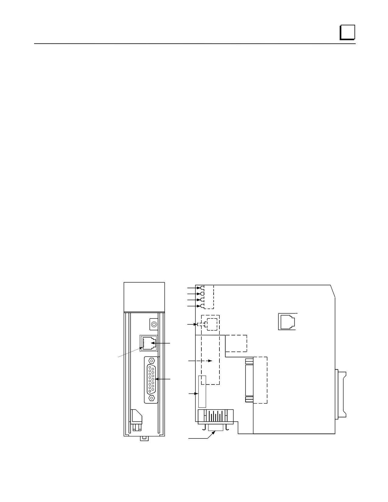
CMM 321
OK
OK
ETHERNET
LAN
LAN
INTERFACE
SER
SER
STAT
STAT
RESTART
STATION
MANAGER
PORT
Pin 1
MAC
ADDRESS
LABEL
FIRMWARE
UPGRAD
PORT
SERIAL
NUMBER
LABEL
TRANSCEIVER
PORT
Figure 8-18. Ethernet Interface Module
GFK-0356Q
Chapter 8 Option Modules
8-29
8
Four LEDs are located at the top of the board. The Restart pushbutton is located immediately
below the LEDs. The RS-232 serial port with the RJ-11 connector is the Station Manager port.
The RS-485 serial port with the 15-pin D connector located below the Station Manager port is the
module’s Downloader port. The 14-pin AAUI connector, facing downward, is the Transceiver
port. The Default MAC Address label is attached to the outside of the plastic housing.
Board Indicators
There are four LEDs on the Ethernet Interface: OK, LAN, SER, and STAT. These LEDs can be
ON, OFF, BLINKING slow, or BLINKING fast. They indicate the state the Interface is in, traffic
on the Transceiver port and Downloader port, and when an exception event has occurred.
Restart Button
The Restart button serves four functions: LED test, Restart, Restart and Reload, and Restart and
Enter Maintenance Utility. The Restart button is inaccessible when the front cover of the Ethernet
Interface is closed.
Serial Ports
There are two serial ports on the Ethernet Interface: the Station Manager Port and the Downloader
Port.
The Station Manager Port. This RS-232 port is used to connect a terminal or terminal emulator
to access the Station Manager software on the Ethernet Interface. This port uses a 6-pin, RJ-11
connector. The IC693CBL316 Station Manager cable is ideal for connecting to this port (see
Chapter 10 for details).
The Firmware Upgrade Port. The 15-pin, D-type, RS-485 port is used to connect to the PC
Downloader in case the communications software in the Ethernet Interface needs to be updated.
Use the IC690ACC901 miniconverter/cable kit for this connection (see Appendix E for details).
AAUI (Transceiver) Port
The 14-pin AAUI port connects to an external Ethernet-compatible transceiver via an IEEE 802.3
transceiver cable. GE Fanuc catalog number IC649AEA102 (for 10Base T) or IC649AEA103 (for
10Base2) are suitable transceivers (see Appendix J for details).
Default MAC Address Label
The Default MAC Address label lists the Ethernet MAC address to be used by this module.
Serial Number Label
The Serial Number Label indicates the serial number of this Interface.
Ethernet Interface Module Documentation
For details, refer to GFK-1541, Series 90-30 TCP/IP Ethernet Communications User’s Manual.
8-30
Series 90-30 PLC Installation and Hardware Manual - August 2002
GFK-0356Q
8
IC693PCM300/301/311 Programmable Coprocessor Module (PCM)
The Programmable Coprocessor Module (PCM) is a high performance coprocessor for the Series
90-30 Modular CPUs (will not work with Embedded CPU models 311, 313, or 323). The PCM
supports the Modbus RTU and GE Fanuc CCM protocols, as well as the MegaBasic and C
programming languages. A free program for using this module as an RTU Master can be
downloaded from the GE Fanuc website. The PCM has two separate ports, both accessed on one
front panel connector.
The PCM is available in three versions. Each version is listed below with the total memory on the
board and the nominal user-available MegaBasic program memory size.
PCM Catalog Number
Total Memory
User Megabasic memory
IC693PCM300
160K
35K
IC693PCM301
192K
47K
IC693PCM311
640K
190K
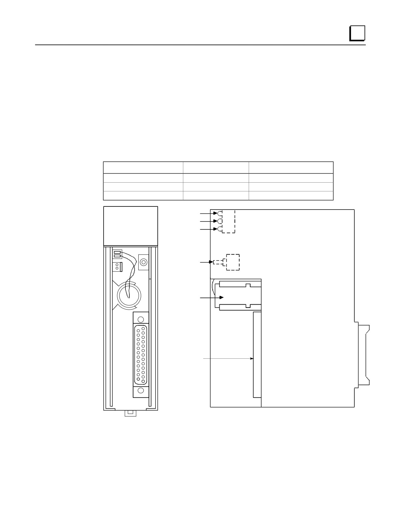
a43734
PCM300
OK
BD OK
COPROC
US1
P1 OK
US2
P2 OK
RESTART
BATTERY
PORTS 1 & 2
CONNECTOR
Figure 8-19. Programmable Coprocessor Module (PCM)
GFK-0356Q
Chapter 8 Option Modules
8-31
8
Applications
These modules are used for communicating with programming terminals, CRTs, bar code readers,
scales, printers, ASCII devices, RTU master devices, etc.
PCM Module Location
A PCM can be installed in any slot in the CPU baseplate only, except slot 1 (labeled CPU/1), which
must contain the CPU module. A PCM will not work in Expansion or Remote racks or in an
Embedded CPU (CPU311, 313, or 323) rack.
Protocols Supported
Modbus RTU and GE Fanuc CCM.
LED Indicator Lights
OK -Normally ON. Indicates the basic condition of the module.
US1 and US2 - By default, LED US1 flashes to indicate activity on Port 1, and LED US2
flashes to indicate activity on Port 2. Both LEDs stay OFF when there is no port activity.
However, the function of these two LEDs can be custom configured by the user. Please see
GFK-0255 for custom configuration details.
Restart Pushbutton
Used to place the module in either the RUN mode or the PROGRAM mode. Please see “PCM
Operation Modes” in GFK-0255, Chapter 1.
Memory Backup Battery
The Lithium battery for backup of RAM memory is installed in a battery mounting clip on the
inside of the PCM faceplate. This battery is disconnected for shipment from the factory and must
be connected prior to installation of the module. When the PCM is stored for extended periods of
time, the battery should be disconnected, unless you wish to retain the program in RAM memory.
Order replacement batteries using catalog number IC693ACC301 (package of two).
Cables
IC693CBL304/305 - These Wye cables split out the two PCM port connections from the single
connector on the front of the PCM modules. One of these cables is supplied with each PCM
module. The IC693CBL304 is for the PCM300. The IC693CBL305 is for the PCM301 and
PCM311. Please see Chapter 10 for details on these cables.
IC690CBL701/702/705 - These cables provides a direct RS-232 connection between the PCM and
various programmers’ serial ports. These cables are not supplied with the PCM modules. Please
see Chapter 10 for details on these cables.
8-32
Series 90-30 PLC Installation and Hardware Manual - August 2002
GFK-0356Q
8
Programmable Coprocessor Module Documentation
GFK-0255, Series 90 Programmable Coprocessor Module and Support Software User’s
Manual
GFK-0256, Megabasic Language Reference and Programmer’s Guide Reference Manual
GFK-0487, Series 90 PCM Development Software (PCOP) User’s Manual
GFK-0771, C Programmer’s Toolkit for Series 90 PCMs User’s Manual
GFK-0356Q
Chapter 8 Option Modules
8-33
8
IC693CMM311 Communications Coprocessor Module (CMM)
The Communications Coprocessor Module (IC693CMM311) provides a high performance
coprocessor for all Series 90-30 modular CPUs (cannot be used with embedded CPUs - models
311, 313, or 323). This module supports the GE Fanuc CCM communications protocol, the RTU
(Modbus) slave communications protocol, and the SNP protocol. This module has two serial ports.
Port 1 supports RS-232 applications and Port 2 supports either RS-232 or RS-485 applications.
The module can be configured using the configuration software, or by using a default setup.
Since both serial ports are wired to the module’s single connector, an IC693CBL305 Wye cable is
supplied with this module to separate the two ports for ease of wiring. A system with a 331 or
higher CPU can have up to four CMMs (in the CPU baseplate only).
a44902
COMM
OK
OK
COPROC
US1
US1
US2
US2
RESTART
COMBINED
SERIAL PORT
PORT1
&
PORT2
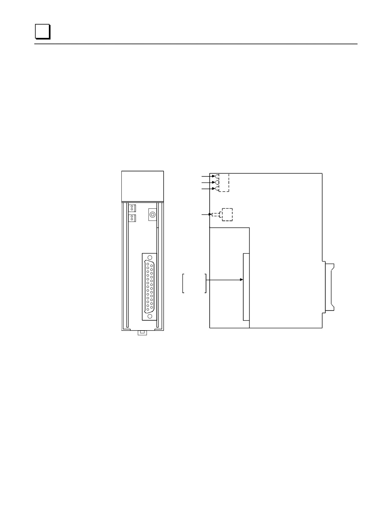
Figure 8-20. Communications Control Module
Communications Control Module Documentation
For more information, refer to GFK-0582, the Series 90 PLC Serial Communications Driver User’s
Manual.
8-34
Series 90-30 PLC Installation and Hardware Manual - August 2002
GFK-0356Q
8
IC693ADC311 Alphanumeric Display Coprocessor (ADC)
The Alphanumeric Display Coprocessor module (IC693ADC311) is a coprocessor to the Series
90-30 PLC CPU and is used in a CIMPLICITY 90-ADS system. It performs CIMPLICITY
90-ADS display, report, and alarm functions when interfaced to an Operator Interface Terminal
(OIT). The OIT can be a variety of GE Fanuc devices, a VT100 compatible terminal, or IBM
compatible personal computer running TERMF. Communications with the Series 90-30 CPU is
done over the PLC system backplane.
ADC311
OK
BD OK
COPROC
P1 OK
US1
US2
P2 OK
RESTART
BATTERY
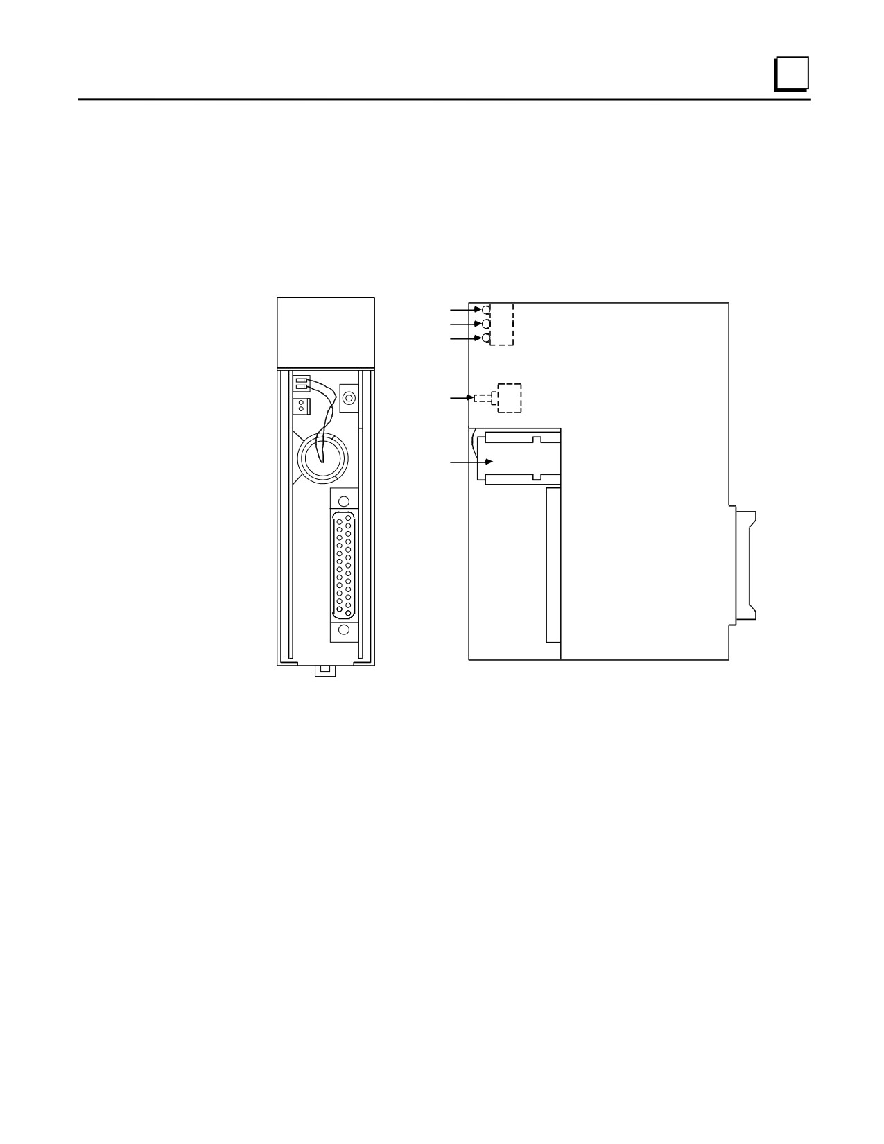
Figure 8-21. Alphanumeric Display Coprocessor Module (ADC)
Features of the Alphanumeric Display Coprocessor include:
■ Single slot module
■ Runs CIMPLICITY 90-ADS System software
■
8 Mhz, 80C188 microprocessor
■ High performance access to PLC memory
■ Real time calendar clock synchronized to PLC
■ Reset pushbutton; three status LEDs
■ Soft Configuration (No DIP switches or jumpers)
■ Easy fill-in-the-blank system building
■ Pop-up windows; pull down menus
■ Fifteen User definable function keys per screen
■ Printer logging to a serial printer
GFK-0356Q
Chapter 8 Option Modules
8-35
8
Multiple Alphanumeric Display Coprocessors can be supported in a single Series 90-30 PLC
system with modular CPU (331 and higher) and must be located in the CPU baseplate. This
module has a single connector which supports two serial ports, with each port being dedicated to a
specific operation. Port 1 is most often used to connect to an RS-232 serial COM port of a
computer running GE Fanuc PCM Development Software (PCOP). Alternately, port 1 may be
connected to a serial RS-232 printer (see the “Cables” section below.). By default, Port 2 is
configured as a 19.2 Kbaud RS-232 port. It can be used to interface to a terminal with keyboard
input and screen output.
Serial port programming and configuration are done using a Workmaster II, Workmaster, or an
IBM-compatible PC, XT, AT, or PS/2 computer with PCM Development Software (PCOP)
installed. The programming computer connects to Port 1 (see the “Cables” section below) . The
default setting is 19,200 bps. The PCM Development Software is used to configure the serial port
parameters and to install the CIMPLICITY 90-ADS software onto the ADC.
There are no DIP switches or jumpers on this board that need to be set for configuration. The ADC
module must be configured with the configuration software prior to use.
Cables
IC693CBL305 - This Wye cable is used to split out the two ADC port connections from the single
connector on the front of the ADC module. This cable is supplied with the module. Please see
Chapter 10 for details on this cable.
IC690CBL702 - This cable provides a direct RS-232 connection between the ADC and another
serial device such as a Personal Computer. This cable is not supplied with the module. Please see
Chapter 10 for details on this cable.
Alphanumeric Display Coprocessor Module Documentation:
See the following manuals for detailed information on Series 90-30 Alphanumeric Display
Coprocessor Modules:
GFK-0499
CIMPLICITY 90-ADS Alphanumeric Display System User’s Manual
GFK-0641
CIMPLICITY 90-ADS Alphanumeric Display System Reference Manual
GFK-0487
Series 90-30 PCM Development Software (PCOP) User’s Manual
8-36
Series 90-30 PLC Installation and Hardware Manual - August 2002
GFK-0356Q
8
IC693TCM302/303 Temperature Control Modules (TCM)
The Temperature Control Modules (TCM) provides temperature control for up to eight channels.
The two TCM models are identical except for temperature range and resolution ratings (see
comparison table). They have the following features:
Can operate in either open loop or closed loop mode
Each channel has a thermocouple input and a relay output
RTD input
12V common mode voltage capability
Open and reverse thermocouple detection and reporting
Out of tolerance temperature detection and reporting
P R F S
Power, Run, Fault,
1
4
and Short LEDs
Output Status LEDs (1 - 8)
5
8
TCM
RTD
PWR
+ 1/P
+ 0/P
Front Cover
Location of Fuse
(Behind Front Cover)
R-
P+
S-
P-
External Power Input
RTD Input
S+
G
R
for Output Relays
1+
1+
1-
1-
2+
2+
2-
2-
Input Connector
3+
3+
Output Connector
3-
3-
4+
4+
4-
4-
5+
5+
5-
5-
6+
6+
6-
6-
7+
7+
7-
7-
8+
8+
8-
8-
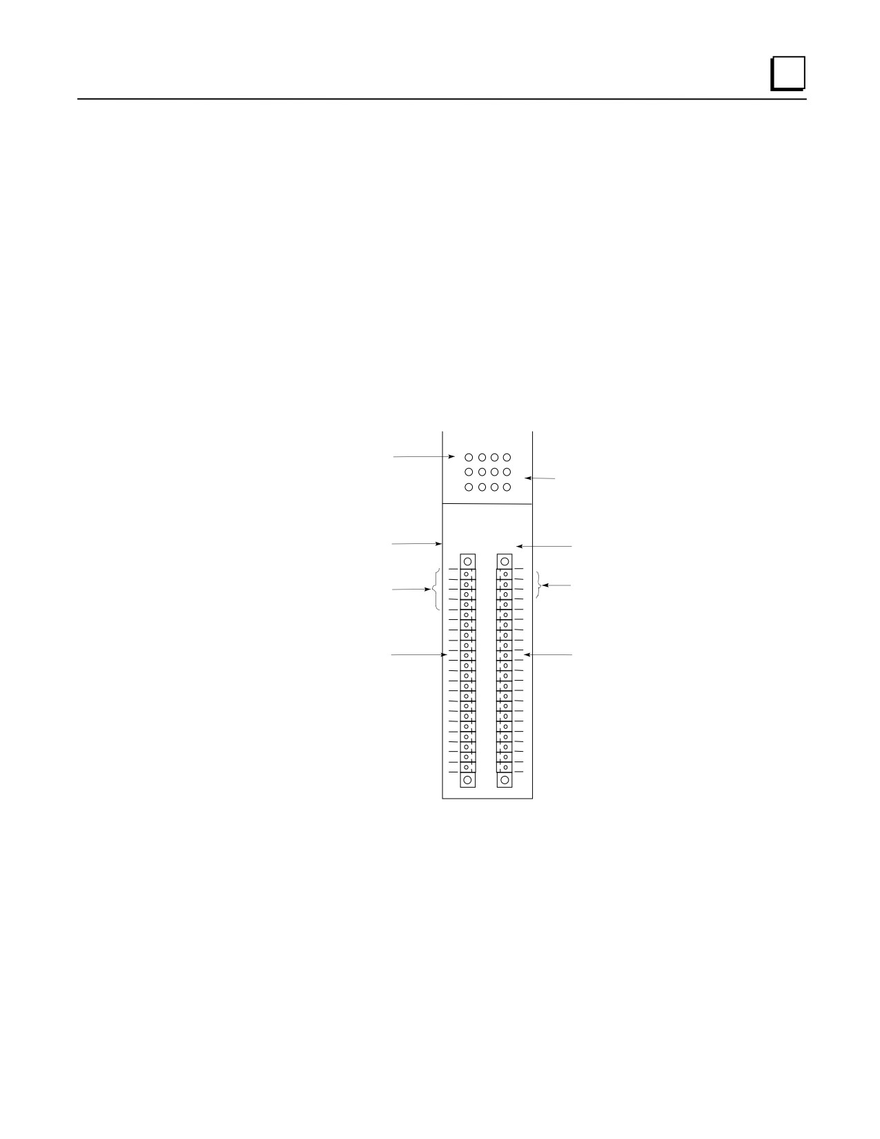
Figure 8-22. IC693TCM302/303 Temperature Control Module (TCM)
Connections
Field devices (thermocouples, relays), RTD and external power for output relays are connected to
the module using a pair of plug-in connectors which are supplied with the module. These
connectors have captive screw terminals for ease of connecting field wiring. The signal name for
each terminal is labeled on the module’s front cover next to each connector, as shown in the
drawing above. For example, Channel 8 connections are labeled 8+ and 8- on each connector.
Input connections are on the left-hand connector and output connections are on the right-hand
connector.
GFK-0356Q
Chapter 8 Option Modules
8-37