FANUC Series 90-30 PLC. Installation and Hardware Manual (GFK-0356Q) - page 6
6
In the rung shown above, the %SA011 contact will close when a low battery is detected by the
PLC. This will turn on the %Q output coil, which addresses an output module’s output that will
turn on a warning light. An alternate method would be to communicate the status of the coil
(which, in that case, would probably be a %M coil) to a Human to Machine Interface (HMI)
terminal such as a GE Fanuc CIMPLICITY HMI unit. The HMI could be programmed to display a
warning message when that particular bit goes to a logic 1. For more information about System
Reference bits and ladder logic programming, see the Series 90-30/20/Micro PLC CPU Instruction
Set Reference Manual, GFK-0467.
GFK-0356Q
Chapter 6 Memory Backup/Battery Backup
6-5
6
Operating Without a Memory Backup Battery
Whether it would be to your advantage to use a battery-less scheme depends on your application.
There are various advantages and disadvantages to consider in making your decision.
Possible Advantage
The obvious advantage of operating without a memory backup battery is that you are freed from
the need to maintain the battery. To be able to run without a battery, you need to have a PROM
device - either an EPROM, EEPROM, or Flash PROM - installed in your system. These devices
can store program logic, configuration, and register values without the need for a backup battery,
and you can configure your CPU to read the contents of PROM into RAM memory each time the
PLC is powered up.
Possible Disadvantages
Information is not stored to your PROM device automatically. To store information, you must stop
the PLC, then use a programming device to tell the CPU to write the current PLC (RAM) memory
contents to the PROM device. This requirement may make battery-less operation undesirable for
many users. For example, in many applications, important data is gathered and stored in RAM
register memory, data such as the current level of material in a tank that is being filled, or a running
count of parts produced, etc. This constantly changing data is not being copied automatically to
the PROM device. It only exists in RAM memory. Therefore, if power is lost and there is no
RAM memory backup battery, this data will be lost.
However, one way to preserve data in a battery-less system is to send it over a network to a
computer that can store the data on its hard drive. Also, static data (data that doesn’t change)
contained in RAM memory, such as mathematical constants or look-up table type information, can
be stored initially in PROM and automatically written back to RAM each time the PLC powers up.
Another consideration is that if you change your program (or configuration), someone will have to
remember to write the changed information to the PROM device. If that step is forgotten, the
change only exists in RAM memory, and in a battery-less system, it will be lost the next time
power is removed from the PLC.
6-6
Series 90-30 PLC Installation and Hardware Manual - August 2002
GFK-0356Q
6
Configuring a Battery-Less System
Here are the basic steps to configure a system to run battery-less. When configured this way, the
contents of PROM memory will be written into RAM memory each time the PLC powers up.
■ Equip your CPU with a PROM device. On some CPUs a PROM device is purchased as an
option; on others, it is a standard feature. For a table that identifies the standard PROM
configuration for each CPU, see “CPU Firmware and PROM Configurations” in chapter 5.
■ There are three CPU configuration parameters involved. Configure them as follows: Pwr Up
Mode: RUN; Logic/Cfg: PROM; Registers: PROM.
■ Store your folder (include Program Logic, Configuration, and Register Data) to the PLC. This
places your entire folder into RAM (working) memory.
■ Write PLC (RAM) memory to the PROM device. Make sure you write all data (Program
Logic, Configuration, and Register Data) to the PROM. Note that the type of PROM device
depends on what model CPU you have and how it is equipped.
■ If you are using a 340 or higher CPU (such as a CPU350, CPU351, etc.), read the next section
for an additional requirement.
Operation Without a Memory Backup Battery Using a 340 or Higher CPU
This information is applicable only to CPU model numbers 340 and higher (such as CPU350,
CPU351, etc.). In systems that do not use a memory backup battery, a standard 0.1” Berg jumper
should be installed across either of the two power supply battery connectors to ensure reliable
restarting of the CPU after a power cycle. This jumper should not be installed if a battery is
plugged into either the power supply or CPU battery connector.
Determining Battery Age Using Battery Date Code
Battery age can be determined from the date code stamped on the battery.
The battery, manufactured by Panasonic, will have a four-digit date code. It will be something like
5615 or 7Y34. Use the following information to determine the date of manufacture.
■ First digit shows the year in a rotating 10-year cycle. For example, 0=1990, 1=1991, 2=1992
... 9=1999, 0=2000, 1=2001, 2=2002, etc. This seeming duplication should not be a problem
because the shelf life of these batteries is 5 years. Batteries in inventory that are older than 4
years old should be discarded according to the manufacturer’s instructions (since they have
less than one year of life remaining we would not recommend using them in a PLC). This will
ensure that outdated batteries are not mistaken for newer batteries.
■ Second digit shows the month. 1=January, 2=February, 3=March, 4=April, 5=May, 6=June,
7=July, 8=August, 9=September, O=October, Y=November, Z=December.
■ Third digit shows the week of the month.
■ Fourth digit shows the day of the week. 1=Monday, 2=Tuesday, 3=Wednesday, 4=Thursday,
5=Friday, 6=Saturday, 7=Sunday.
For example, the code 7612 is interpreted as:
Manufactured on June 3, 1997
GFK-0356Q
Chapter 6 Memory Backup/Battery Backup
6-7
6
RAM Memory Battery Backup Connection Path
CMOS RAM and DRAM memory is a volatile type of memory, which means that it can lose its
contents (ladder program, configuration, etc.) if power is removed. To retain RAM memory
contents under no-power conditions, a long-life lithium battery is provided. This battery is
normally mounted in the rack’s Power Supply module. To avoid accidental disconnection of the
memory backup battery, it is beneficial to know the connection path between the battery and the
memory circuits:
For embedded CPUs: The battery connection path to RAM memory is through the Power
Supply’s baseplate connector and across the backplane board to the RAM circuits.
For modular CPUs: The battery connection path to RAM memory is through the Power Supply’s
baseplate connector, across the backplane board, and through the CPUs baseplate connector to the
RAM circuits inside the CPU module.
Obviously, removing the Power Supply module from the PLC breaks the connection between the
backup battery and the RAM memory circuits for both embedded and modular CPUs. Also, in a
modular CPU system, removing the CPU module would disconnect the backup battery from the
memory circuits. In addition, to avoid the possible problems associated with losing the contents
of RAM memory, we recommend that you maintain an up-to-date backup copy of your program
folder. Instructions for creating program folder backups can be found in the Logicmaster 90,
Series 90-30 Programming Software User’s Manual, GFK-0466, and the online help and user’s
guides for the Windows-based programming software products.
Super Capacitor Memory Backup
Besides the backup battery, the RAM memory circuits in both Embedded and Modular CPUs are
further protected by a ”super capacitor,” which can store enough charge to maintain memory for a
short time if the battery is disconnected. The amount of protection time provided by the super
capacitor depends on the following:
■ The PLC power supply supplies 5 VDC to the memory circuits, including the super capacitor.
Therefore, when PLC power is turned off, the super capacitor has an initial 5 VDC charge. If
the battery is also disconnected shortly after PLC power is turned off, the super capacitor will
begin discharging from the 5 VDC level until its charge reaches 2 VDC, at which time
memory contents will be lost. When used this way, the super capacitor can maintain memory
contents for a minimum of 1 hour.
■ The memory backup battery supplies 3 VDC to the memory circuits, including the super
capacitor. Therefore, if PLC power has been turned off for an hour or more and only the
battery is powering the memory circuits, the super capacitor has a 3 VDC charge. Then, if the
battery is disconnected, the super capacitor will begin discharging from the 3VDC level until
its charge reaches 2 VDC, at which time memory contents will be lost. When used this way,
the super capacitor can maintain memory contents for a minimum of 20 minutes.
6-8
Series 90-30 PLC Installation and Hardware Manual - August 2002
GFK-0356Q
6
Maintaining RAM Memory During Storage or Shipment of a CPU
Modular CPUs
Modular CPUs have an internal connector for a backup battery so that RAM memory contents can
be retained while the CPU is being stored or shipped. This arrangement should not to be used
when the CPU module is installed in the baseplate and the backup battery is installed in the power
supply. To use a backup battery in the CPU module, it is necessary to remove the front cover of
the CPU module. This can be accomplished by following these steps:
■ To avoid losing memory contents once the CPU is removed from the PLC, we recommend you
install the backup battery into the CPU within 20 minutes. First, make sure PLC power is off,
then remove the CPU module.
■ Gently squeeze the front cover of the CPU module and pull it forward, away from the module
case, while gently pressing in on the 4 front cover tabs sequentially with a small screwdriver.
The front cover tabs latch into holes on each side of the module case (refer to Figure 2-1 for
location of front cover holding tabs).
■ After removing the front cover, plug the memory backup battery into the two-prong battery
connector on the front of the CPU module’s printed circuit board.
■ While the battery is connected to the CPU, you will have to leave the CPU’s front cover off.
Also, the battery should be temporarily secured to the module with cable ties or tape to keep it
from being accidentally damaged or disconnected.
The Battery Accessory Kit, described below, may also be used on a Modular CPU baseplate if the
power supply has to be removed. This would require leaving the CPU module mounted in the
baseplate.
Long-term battery backup can be provided with the use of the External Battery Module, described
on page 6-10.
Embedded CPUs
Embedded CPU Models 311, 313, and 323 can be stored or shipped with a power supply installed
and the power supply battery connected in order to maintain the contents of RAM memory.
However, another option (that doesn’t require the use of a power supply) is to use the Battery
Accessory Kit, described next.
Battery Accessory Kit (IC693ACC315)
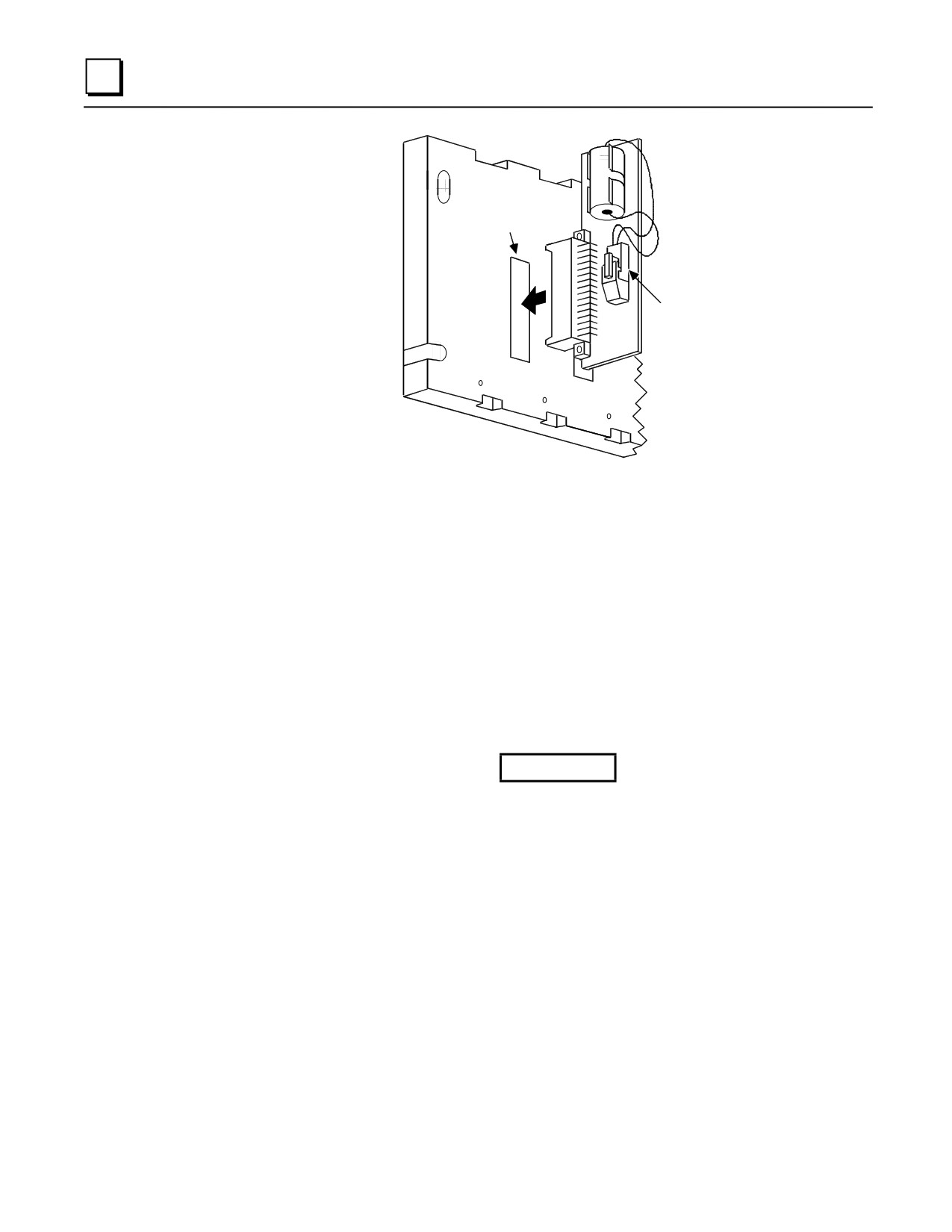
The Battery Accessory Kit (IC693ACC315) lets you maintain RAM memory contents without
using a power supply. It is useful for maintaining memory contents while a baseplate is being
stored or shipped. The Battery Accessory Kit consists of a battery with an attached connector
mounted on a circuit board. The circuit board has a connector that plugs into the power supply
backplane connector (see the figure below). The Battery Accessory Kit can be used on either
Embedded or Modular Series 90-30 CPU baseplates.
GFK-0356Q
Chapter 6 Memory Backup/Battery Backup
6-9
6
POWER
SUPPLY
CONNECTOR
BATTERY
PLUG
Figure 6-2. Installing the Battery Accessory Kit
Battery Accessory Kit Installation
1. Insert the plug on the end of the battery cable into the 2-pin connector on the Battery Accessory
board. The battery plug is normally not plugged into the accessory connector. This prevents
accidental discharge of the battery during storage and handling.
2. Align the backplane connector on the Battery Accessory board with the power supply
connector on the baseplate backplane. Push the Battery Accessory board toward the baseplate
until it is fully seated. See the figure above.
3. If the baseplate is to be shipped with the Battery Accessory board installed, ensure that the
board is held in place by packing material or cable ties. The cable ties can be installed in holes
provided on both ends of the accessory board and secured to the baseplate.
Caution
To avoid losing CPU data, the Battery Accessory must be installed within 1
hour after turning off PLC power, or 20 minutes after removing the memory
backup battery. See “Super Capacitor Memory Backup” for details.
When the Battery Accessory is removed, a power supply module with a good
battery must be installed and/or input power applied within 20 minutes to
avoid losing CPU data. See “Super Capacitor Memory Backup” for details.
External Battery Module (IC693ACC302)
This module provides long-term battery backup for all modular Series 90-30 CPUs. Its two-foot
cable plugs into the power supply battery connector. The External Battery Module maintains RAM
contents on a CPU374 for 15 months. CPU models 331—364 maintain RAM contents for
approximately 75 months. For details, see the Datasheet for the External Battery Module,
GFK-2124.
6-10
Series 90-30 PLC Installation and Hardware Manual - August 2002
GFK-0356Q
6
Batteries in Power Supplies on Expansion or Remote Racks
Batteries in power supplies on Expansion or Remote racks, are not in use. Only the battery in a
CPU rack supplies backup power to RAM memory. Batteries in non-CPU racks may be removed
and used as spares, if they meet the age requirements stated previously in this chapter.
GFK-0356Q
Chapter 6 Memory Backup/Battery Backup
6-11
Chapter
Input/Output Modules
7
The basics of the Series 90-30 Input and Output (I/O) modules are covered in this chapter for your
convenience. A table listing these modules is located at the end of this chapter. For detailed
specifications and installation instructions, please refer to publication GFK-0898, Series 90-30 PLC
I/O Module Specifications.
Basic I/O Module Types
■
Discrete Input
Series 90-30 discrete input modules convert AC and DC power levels from user devices to the
logic levels required by the PLC. An optical coupler provides isolation between the incoming
power and the logic circuitry. Discrete input modules with 8, 16, or 32 points are available.
■
Discrete Output
Series 90-30 discrete output modules convert logic levels into AC or DC power levels required
for driving user supplied devices. Either a power semiconductor or an electromagnetic relay
switches each output point. The discrete output semiconductor-switched modules are available
with 5, 8, 12, 16, or 32 output points. Relay output modules are available with either 8 or 16
Normally Open relay contact outputs.
■
Discrete Input/Output
Combination discrete input/output modules combine AC inputs and relay outputs or DC
inputs and relay outputs on one module. Each of these modules have 8 input circuits and 8
relay output circuits on one board.
■
Analog Input
Series 90-30 analog input modules provide A/D (Analog to Digital) conversion by converting
an analog input signal into a scaled digital number which will be transferred into the PLC’s
%AI memory. Analog input modules are provided in four versions, (1) a 4-channel current
module, (2) a 4-channel voltage module, (3) a 16-channel high-density current input module,
and (4) a 16-channel high-density voltage input module.
■
Analog Output
Series 90-30 analog output modules provide D/A (Digital to Analog) conversion by converting
a scaled digital number (from the PLC’s %AQ memory) into an analog output voltage. Analog
GFK-0356Q
7-1
7
output modules are provided in three versions, (1) a 2-channel current module, (2) a 2-channel
voltage module, and (3) a high-density current/voltage module with 8 analog output channels.
■ Analog Combination Module
An analog combination module provides four A/D input channels and two D/A output
channels on one module. Each of the input and output channels can be configured individually
for current or voltage mode.
■ Third-Party Modules
In addition to the modules discussed in this chapter, numerous third-party I/O modules (and
other hardware and software products) for the Series 90-30 PLC are available to meet a wide
variety of needs. For information on third-party modules, consult the following:
-
Your GE Fanuc PLC distributor or sales engineer
-
The GE Fanuc web site at http://www.gefanuc.com
Discrete I/O Modules
Discrete I/O Module Point Density
There are two density categories for these modules:
■ Standard Density Modules: Standard density modules have up to 16 circuits (also called
“points”) per module. These modules are equipped with a removable terminal board. See the
following figure.
■ High Density Modules: High density modules have 32 circuits per module. These modules
have either a 50-pin connector, or two 24-pin connectors mounted on their faceplates.
Connection choices are discussed later in this chapter.
Standard Density Discrete I/O Module Features
Standard Density(16 points or less) Modules have the following features (refer to the following
figure):
■ Removable Terminal Board. You can remove the terminal board from the module in order
to wire it, if desired. Then, when you are finished wiring it, you can easily reinstall it on the
module. However, some prefer to leave it on the module when wiring. If you ever need to
replace a module, you don’t have to do any rewiring if your old terminal board is still in good
condition. Simply remove the wired terminal board from the old module and install it on the
new module. The terminal board screw terminals are also convenient points for measuring
voltages while testing or troubleshooting.
■ Hinged Front Cover. The cover is easily opened to access the terminal board connections.
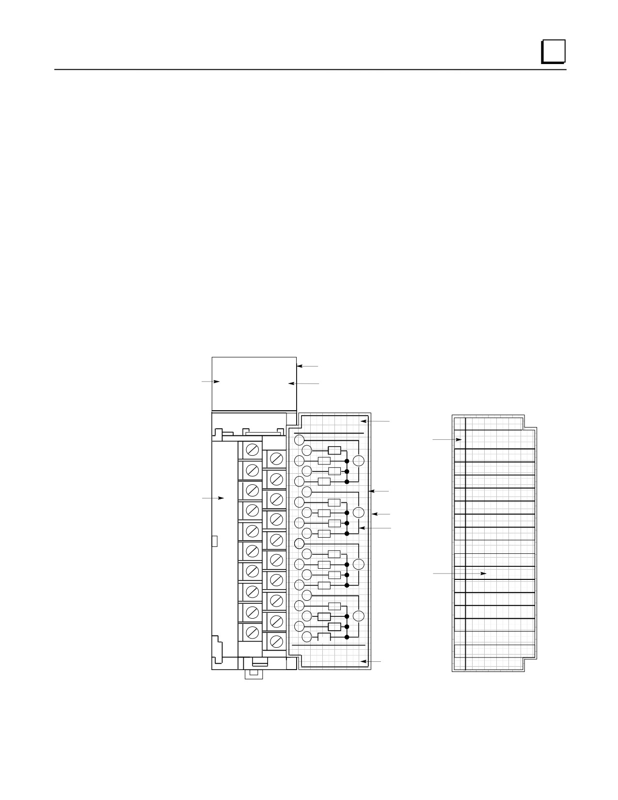
Normally it’s kept closed to protect personnel from accidentally touching a hot terminal. Note
in the following figure that the back side of the front cover insert contains a schematic diagram
of the terminal board connections. The module catalog number (IC693MDL940 in the
example shown) is printed on the bottom of the front cover insert. The module catalog
7-2
Series 90-30 PLC Installation and Hardware Manual - August 2002
GFK-0356Q
7
number is also printed on the label on the side of the module. However, in order to see this
side label, the module has to be removed from the PLC
On the front side of the front cover insert are lines that correspond to the module’s I/O points.
You can temporarily remove the insert and write the signal name for each point on the
appropriate line, as shown in the example in the figure.
Also on the front side of the front cover insert, running vertically on the left edge of the insert,
is a color bar that identifies the type of module: Blue = DC, Red = AC, and Gray = Analog.
■
Module Lens Cap. Located on the top front of the module, it covers the LED (Light Emitting
Diode) status lights . These are labeled in the following figure in two groups, A1 through A8,
and B1 through B8. Since this is a figure of a 16-Point Output module, there are 16 LED
status lights.
(The number of status lights on any given module is a function of the number of
circuits points on that module.) If you compare these status lights to the connection diagram
on the back of the hinged cover, you will notice that the outputs on this module are in two
groups, labeled A1-A8 and B1-B8, that correspond to the A and B rows of status LEDs. Note
the additional LED on the right side of the lens cap that is labeled with the letter F. This is a
blown fuse indicator light. This letter F is present on all of the discrete I/O module lens caps,
but is only functional on certain Output Modules that have internal fuses. It only lights if an
internal fuse is blown. A table with a list of modules having fuses as well as other details
about the status LEDs is provided in Chapter 13 of this manual.
a43082A
Lens Cap
A1 2 3 4 5 6 7 8
STATUS
F
Fuse Indicator
LEDs
B1 2 3 4 5 6 7 8
Hinged Cover
Front View
OUTPUT
Module Type
RELAY N.O.
2 AMP
OUTPUT
1
Color Bar
RELAY N.O. 2 AMP
Indicates
2
AA1
of Module
A1
Pilot
3
A2
V
A2
Pilot
4
AA3
5
A4
A3
Contro
6
Removable
A4
Emargenc
Removable
Insert
Terminal
7
A5
A5
Pump 1 ON
Board
8
A6
V
HInged Cover
9
A7
A6
Pump 2 ON
Connection
10
A8
Diagram on
A7
Motor Starter 1
Back of Insert
11
A8
MotorStarter
12
B1
B1
CR 1
13
B2
V
User can Write
B2
CR 2
14
B3
Signal Names on
15
B4
Front of Insert
B3
CR 3
16
B4
CR 4
17
B5
B5
SOL 1
18
B6
V
B6
SOL 2
19
B7
20
B8
B7
SOL 3
44A726782-015
B8
SOL 4
FOR USE WITH
Module Catalog
IC693MDL940
Figure 7-1. Example of Series 90-30 Standard Density Discrete Output Module
GFK-0356Q
Chapter 7 Input/Output Modules
7-3
7
Wiring Standard Density (16-Point or Less) Discrete Modules
There are three basic wiring methods:
■ Direct Method. Run the wires from the field devices (switches, relays, etc.) directly to the
screws on the modules’ terminal boards.
■ Terminal Strip Method. Mount a terminal strip inside the control enclosure and wire from
the terminal strip to the modules’ terminal boards. Then wire field devices to the terminal
strip.
■ Terminal Block Quick Connect Assembly Method. The Terminal Block Quick Connect
Assembly has three pieces: a faceplate, a cable, and a terminal block. The faceplate snaps onto
an I/O module in place of its normal terminal board. This faceplate has a connector that mates
with the cable. In turn, the cable plugs into a connector on the terminal block. The terminal
block mounts on a DIN-rail in a convenient place in your enclosure. The terminal block is
used for connecting to field devices such as switches and relays. This method saves, on the
average, over two hours of wiring time per module when compared with the Terminal Strip
method. For more information, see Appendix J, “Terminal Block Quick Connect
Components.”
Discrete Relay Output Module Protection
Output points on discrete relay output modules that switch an inductive load such as a relay coil,
lamp filament, or solenoid coil should have external protection. This is usually in the form of an R-
C (Resistor-Capacitor) network across an AC load, or a reverse-biased diode across a DC load.
Please see GFK-0898, Series 90-30 PLC I/O Module Specifications, for details.
High Density (32-Point) Discrete Module Features
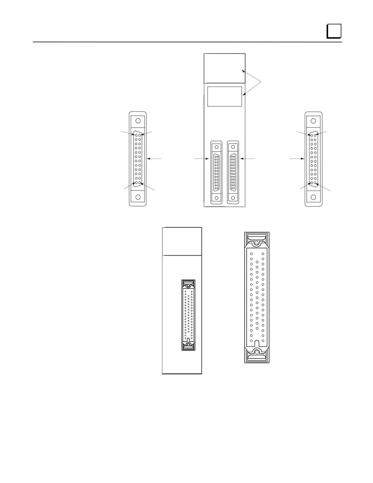
■ There are two types of these modules. One type has a single 50-pin connector on its faceplate,
the other type has a pair of 24-pin connectors on its faceplate (see next two figures).
■ The dual 24-pin type has LED status indicators. The 50-pin type does not. The LED status
indicators are arranged in four groups of eight across, labeled A, B, C, and D. They are
located at the top of the module (see next figure).
■
32-point modules are only available in 5, 12, and 24 VDC ratings.
■ None of the 32-point modules are fused.
■ These modules are useful in applications where a high count of DC I/O points is required. The
maximum number of I/O points for a Series 90-30 system can be obtained by using a CPU that
supports a total of eight 10-slot racks, and by populating the racks with 32-point modules. The
theoretical maximum number of I/O points possible is calculated by adding the nine available
slots in the CPU rack (the CPU must occupy one slot) to the 70 slots in the seven 10-slot
expansion or remote racks to get a total of 79 slots. Multiply 79 times 32 for a maximum of
2,528 I/O points (only CPUs 350 - 364 support this many I/O points). This assumes that every
slot is populated with a 32-point I/O module. Most practical applications require some slots
for option modules, reducing the number of slots available for I/O modules accordingly.
7-4
Series 90-30 PLC Installation and Hardware Manual - August 2002
GFK-0356Q
7
A1 2 3 4 5 6 7 8
B1 2 3 4 5 6 7 8F
LED Indicators
C1 2 3 4 5 6 7 8
D1 2 3 4 5 6 7 8
INPUT
5/12 VDC
POS/NEG LOGIC
3.0 mA/Pt at 5VDC
Pin B12
Pin A12
8.5 mA/Pt at 12VDC
Pin A1
CD
AB
Left Side
Right Side
Connector
Connector
Pin B1
Pin A12
Pin A1
Figure 7-2. Example of 32-Point I/O Module (IC693MDL654) With Dual Connectors
33
1
19
INPUT 32 PT
24 VDC ISOL
NEG/POS LOGIC
32
18
50
7.5 mA/Pt
Connector Pin
Numbering
Figure 7-3. Example of 32-Point I/O Module (IC693MDL653) With Single Connector
GFK-0356Q
Chapter 7 Input/Output Modules
7-5
7
Wiring Methods for 32-Point Discrete I/O Modules
Modules with Single 50-Pin Connector
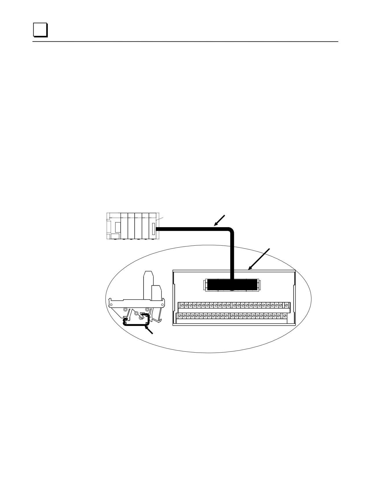
Three choices are available for connecting these modules.
■ Connect to a Weidmuller #912263 terminal block using one of the two GE Fanuc “extension”
cables (see next figure). Cable IC693CBL306 is 3 feet (1meter) long. Cable IC693CBL307 is
6 feet (2 meters) long. Chapter 10, “Cables,” has details on these cables.
■ Connect to a user-supplied terminal block/strip or I/O field devices using one of the two GE
Fanuc “interface” cables. These cables have a 50-pin connector on one end that plugs into the
module, and stripped, tinned leads on the other for wiring to a terminal block/strip or I/O field
devices. Cable IC693CBL308 is 3 feet (1 meter) long, and cable IC693CBL309 is 6 feet (2
meters) long. These cables are useful if you have to run your wiring through conduit that is
too small for a connector to fit through.
■ Build a custom length cable. This is required if you need a cable longer than 6 feet (2 meters).
See the IC693CBL308/309 data sheet in Chapter 10 for pin-out details.
IC693CBL306/30
50-Pin, 32-Point
Extension Cable
I/O Module
a44838A
Weidmuller 912263
Terminal Block
Series 90-30 PLC
50
End
View
1
26 27
28
29 30 31 32 33 34 35 36 37
38 39 40 41
42 43 44 45
46
47 48 49
50
1
2
3
4
5
6
7
8
9
10
11 12
13 14
15 16 17 18
19
20
21 22 23 24
25
Top
Mounts on
View
DIN-Rail
Figure 7-4. 50-PIN, 32 Point I/O Module Connection Method
7-6
Series 90-30 PLC Installation and Hardware Manual - August 2002
GFK-0356Q
7
Modules with Dual 24-Pin Connectors
Three choices are available for connecting these modules
■ Connect to a pair of Terminal Block Quick Connect (TBQC) terminal blocks (IC693ACC337)
using a pair of GE Fanuc cables. Three lengths of cables are available: 20” (0.5 meter), 3 feet
(1 meter), 6 feet (2 meters). The cables come in right hand and left hand types because the
connectors on the modules are oriented differently (see figure 7-2). For details on the terminal
blocks and cables, please see Appendix J.
■ Connect to user supplied terminal block/strip or directly to I/O field devices using a pair of 10
foot (3 meter) GE Fanuc interface cables. These cables have 24-pin connectors on one end for
connecting to the module, and stripped, tinned leads on the other for wiring to a terminal
block/strip or I/O devices. Cable IC693CBL327 is for the left side and IC693CBL328 is for
the right side. These cables are useful if you have to run your wiring through conduit that is
too small for a connector to fit through, or if you need a cable longer than six feet. Chapter 10,
“Cables,” has details on these cables.
■ Build a custom length cable. This is required if you need a cable longer than 10 feet (3
meters). See the IC693CBL327/328 data sheet in Chapter 10 for details on building custom
length cables.
GFK-0356Q
Chapter 7 Input/Output Modules
7-7
7
Analog Module Features
Analog Modules have the following basic features (refer to the following figure):
■
Removable Terminal Board. You can remove the terminal board from the module in order
to wire it, if desired. Then, when you are finished wiring it, you can easily reinstall it on the
module. However, some prefer to leave it on the module when wiring. If you ever need to
replace a module, you don’t have to do any rewiring if your old terminal board is still in good
condition. Simply remove the wired terminal board from the old module and install it on the
new module if it is good condition. The terminal board screw terminals are also convenient
points for measuring voltages while testing or troubleshooting.
■
Hinged Front Cover. The cover is easily opened to access the terminal board connections.
For normal operation, it is kept closed to protect personnel from accidentally touching a hot
terminal. Note in the following figure that the back side of the front cover insert contains a
schematic diagram of the terminal board connections. The module catalog number
(IC693ALG391 in this example) is printed on the bottom of the front cover insert. The module
catalog number is also printed on the label on the side of the module. However, in order to
see this side label, the module has to be removed from the PLC
■
On the front side of the front cover insert are lines that correspond to the module’s I/O points.
You can temporarily remove the insert and write the signal name for each point on the
appropriate line to aid in testing or troubleshooting.
■
Also on the front side of the front cover insert, running vertically on the left edge of the insert,
is a colored line that identifies the type of module: Blue = DC, Red = AC, and Gray = Analog.
■
Module Lens Cap. Located on the top front of the module, it covers the LED (Light Emitting
Diode) OK status light. This light indicates the basic status of the module. For normal
operation, the OK LED should be on.
7-8
Series 90-30 PLC Installation and Hardware Manual - August 2002
GFK-0356Q
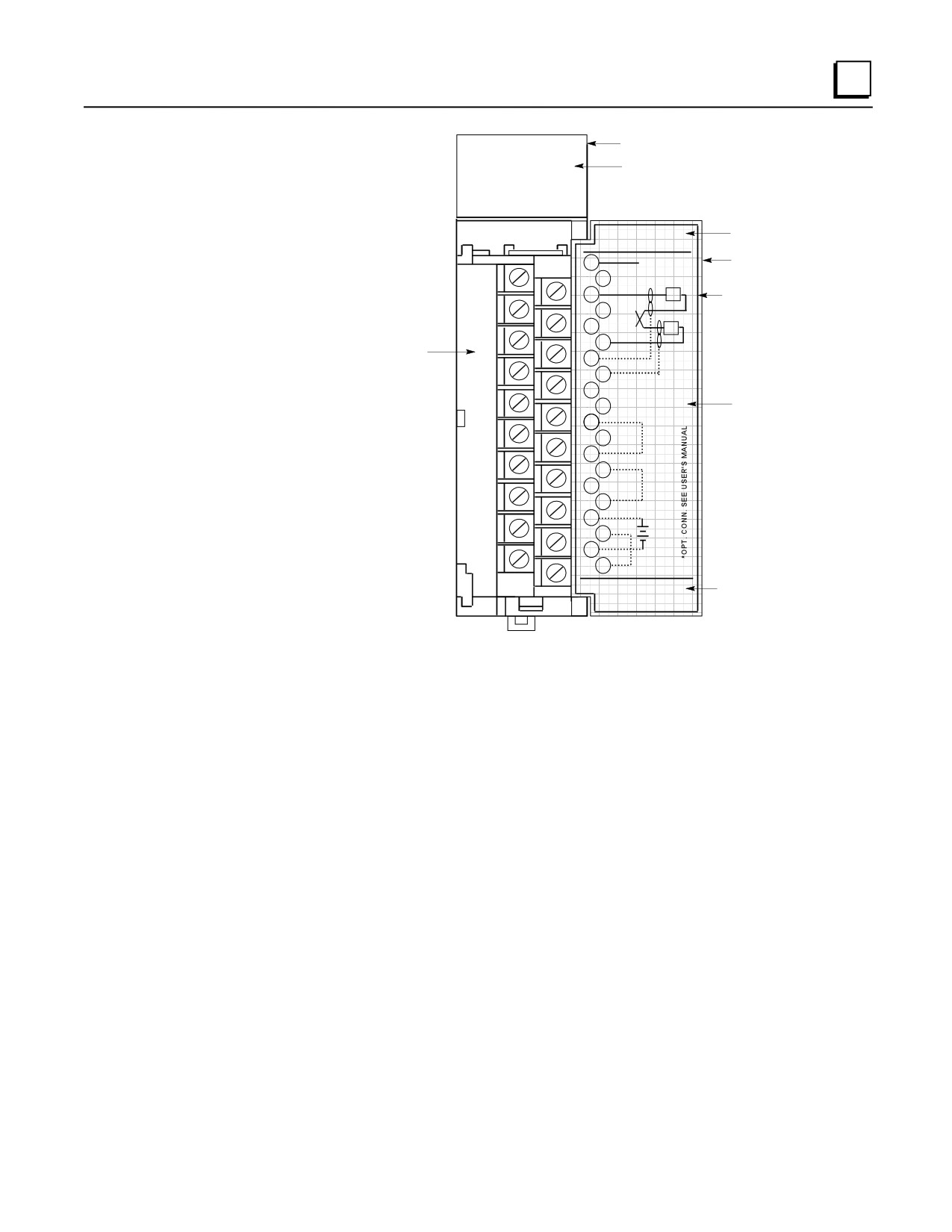
7
Lens Cap
OK
Module OK LED
OUTPUT
Module Type
ANALOG
CURRENT
VOUT1
Hinged Cover
1
VOUT2
2
A1
IOUT1
3
A2
1
Removeable
IOUT2
Insert
4
A3
RTN1
5
A4
2
RTN2
Removeable Terminal
6
GND
Board
7
GND
8
JMPV1
9
Connection
JMPV2
10
Diagram
DEF0
11
12
13
0-20mA
14
CH1
15
16
17
+
18
24V
-
19
CH2
20
0-20mA
Module Catalog
44A729182-021R01
No.
FOR USE WITH
IC693ALG391
Figure 7-5. Example of Series 90-30 Analog Current Output Module
Wiring Methods for Analog Modules
Twisted, shielded instrumentation cable is strongly recommended for analog module input or
output signal connections. Proper grounding of the shield is also important. For maximum
electrical noise suppression, the cable shield should only be grounded at one end of the cable. For
Input modules, ground the end that is in the noisiest environment (which often is at the field device
end). For Output modules, ground at the module end. See GFK-0898, Series 90-30 PLC I/O
Module Specifications, for more shield grounding information.
Analog Input Module Wiring Methods
Correcting electrical noise problems can sometimes be a trial-and-error routine. However, in
general, it is generally best to ground the cable shield as close to the source of the noise as possible,
which is usually at the device end. In troubleshooting noise problems, sometimes it is beneficial to
experiment with the shield grounding point location. Remember, the cable shield should be
grounded at one end only. Also, it is best to keep the length of stripped cable leads as short as
possible to minimize the length of unshielded conductors that will be exposed to the noisy
environment. See the Series 90-30 PLC I/O Module Specifications Manual, GFK-0898 for
additional details.
GFK-0356Q
Chapter 7 Input/Output Modules
7-9
7
■ Direct Method. Run a shielded cable from the field device (transducer, potentiometer, etc.)
directly to the module. Connect the conductors to the applicable screws on the module’s
terminal board. Ground the shield at the field device end, exposing a minimum amount of
conductor to the noisy environment. Do not connect the shield at the module end (insulate it
with shrink tubing).
■ Terminal Strip Method. Mount a terminal strip inside the control enclosure and run a
shielded cable from the terminal strip to the module’s terminal board terminals. Connect the
shield to the metal panel next to the terminal strip. Do not connect the shield at the module
end (insulate it with shrink tubing). Wire the field device to the terminal strip with a shielded
cable, grounding the shield at the device end only (insulate the other end of the shield with
shrink tubing). Also, keep the length of exposed leads at the terminal strip and device ends as
short as possible.
Note
TBQC - The Terminal Block Quick Connect Assembly is not recommended for
use with analog modules due to cable shielding requirements.
Analog Output Module Wiring
Each output should be connected using a good quality shielded wire with the shield grounded at the
module end only. See GFK-0898, Series 90-30 PLC I/O Module Specifications, for more
information.
I/O Module Power Supply Current Draw
These values are found in Chapter 12 of this manual, which discusses how to calculate power
supply loading. The information is also found in GFK-0898, Series 90-30 PLC I/O Module
Specifications.
7-10
Series 90-30 PLC Installation and Hardware Manual - August 2002
GFK-0356Q
7
I/O Module Wire Routing
To reduce noise coupling among PLC wires, it is recommended you keep electrically noisy wiring,
such as AC power wiring and Discrete Output Module wiring, physically separated from low-level
signal wiring such as connections to DC and Analog Input modules. This can be accomplished by
grouping separately, where practical, the following categories of wiring:
■ AC power wiring. This includes the AC input to the PLC power supply, as well as other AC
devices in the control cabinet.
■ Analog Input and Output Module wiring. This should also be shielded to further reduce
noise coupling.
■ Discrete Output Module wiring. These often switch inductive loads that produce noise
spikes when switched off.
■ DC Input Module wiring. Although suppressed internally, these low-level inputs should be
further protected against noise coupling by observing these wiring practices.
Grouping Modules to Keep Wires Segregated
If practical, grouping similar modules together in the PLC racks can help keep wiring segregated.
For example, one rack could contain only AC modules and a different rack only DC modules, with
further grouping in each rack by input and output types. For smaller systems, as an example, the
left end of a rack could contain Analog modules, the middle could contain DC modules, and the
right end could contain AC modules. Where AC or Output wiring bundles must pass near low-
level signal wiring bundles, avoid running them beside each other. Route them so that, if they have
to cross, they do so at a right angle. This will minimize coupling between them.
GFK-0356Q
Chapter 7 Input/Output Modules
7-11
7
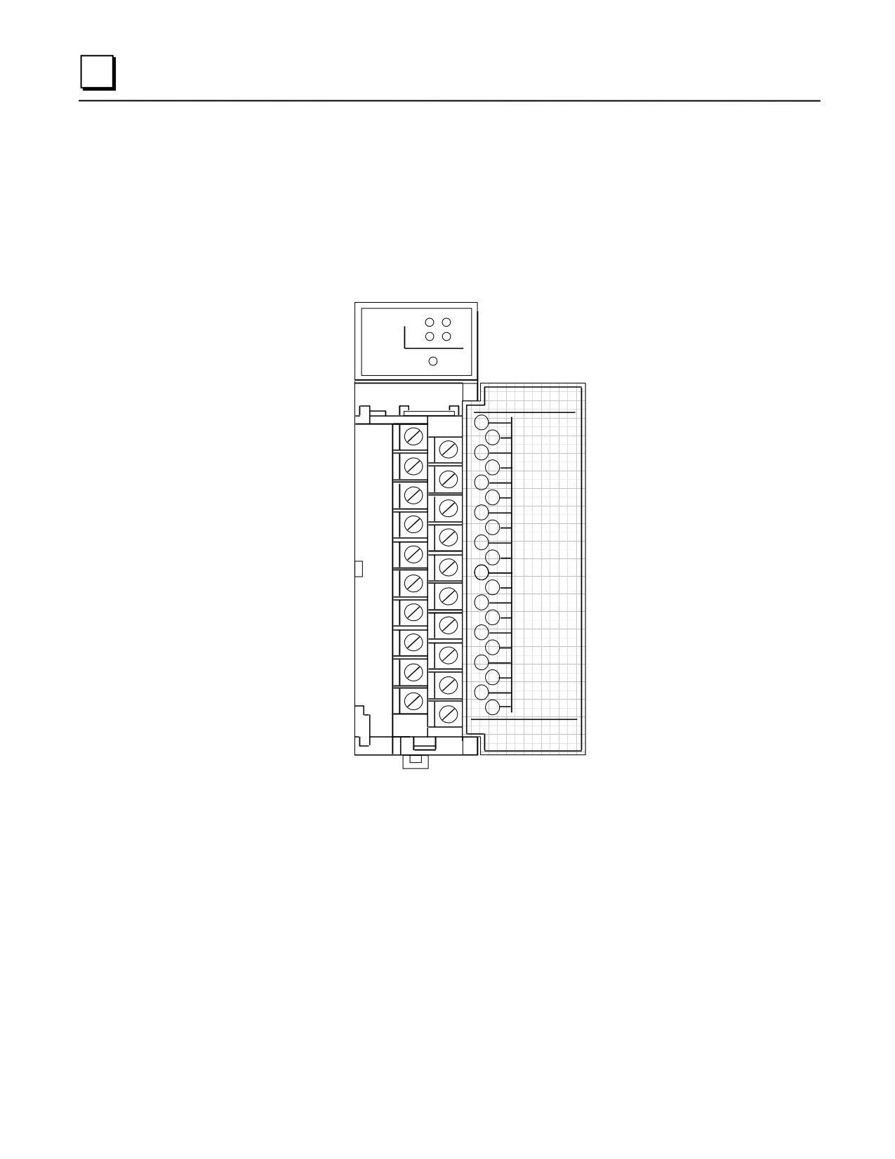
IC693DVM300 Digital Valve Driver Module
This 4-channel digital valve driver module is capable of driving loads of up to 1.6 Amps at 24
VDC. Although it mounts in a standard Series 90-30 PLC slot, it does not connect to the PLC
backplane. Its control power and output power come from an external supply. (The GE Fanuc
IC690PWR124 stand-alone power supply would be a suitable choice.) This module is designed for
TTL (5 VDC) inputs.
DIG CH:
1
3
2
4
PWR
OUTPUT
28V 1.6A max.
1
+28V.IN
2
+28V.RET
3
AUX.OUT.+15
4
AUX.OUT.-15
5
DIGITAL.1.IN
6
DIGITAL.2.IN
7
DIGITAL.3.IN
8
DIGITAL.4.IN
9
DIGITAL.RET
10
+28V1.IN
11
+28V2.IN
12
28V1&2.RET
13
VALVE.1.OUT
14
VALVE.1.RET
15
VALVE.2.OUT
16
VALVE.2.RET
17
VALVE.3.OUT
18
VALVE.3.RET
19
VALVE.4.OUT
20
VALVE.4.RET
Figure 7-6. IC693DVM300 Digital Valve Driver Module
Indicator LEDs
■ DIG CH: 1 - 4: These light when their corresponding input is at a Logic 1 level.
■ PWR: Lights to indicate the presence of +26 VDC (nominal) input power on terminals 1
and 2.
7-12
Series 90-30 PLC Installation and Hardware Manual - August 2002
GFK-0356Q

7
DVM Specifications
Table 7-1. IC693DVM300 Specifications
OUTPUT CHARACTERISTICS
Outputs (Channels) per Module
4
Isolation
2500 Vrms (optical isolation)
Nominal Output Voltage
24 VDC
Power Supply for Output Channels
26 VDC nominal, 21 VDC minimum, 35 VDC
maximum
Output Current
1.6 Amps maximum per channel
6.4 Amps maximum total per module
Output Voltage Drop (fully loaded)
0.32 VDC
Off state leakage current
26 ∝A at 26 VDC operating voltage
Turn-on response time
< 1 ∝S with resistive load
Turn-off response time
< 1 ∝S with resistive load
Output protection (per channel)
Reversed-biased zener diode for free-wheeling
inductive current. Also 36 Volt transorb for
ESD and surge protection.
INPUT CHARACTERISTICS
Input Voltage
5 VDC (TTL) nominal, 12Vdc Maximum
Logic 1 Level
Logic 1: V > 3.5 VDC
Logic 0: V < 0.7 VDC
Input Current
3.8 mA nominal
Input protection
13.3 Volt transorb
AUXILIARY POWER SUPPLY OUTPUTS
Voltage and Current
+15 VDC @ 0.3A and -15 VDC @ 0.2A
Isolation
Not isolated
MODULE POWER REQUIREMENTS
Power Consumption (Does not consume
5.6 Watts (with all outputs on) from external
any power from PLC backplane.)
supply connected to terminals 1 and 2 (does
not include power consumed by outputs)
Input Voltage
+26 VDC nominal, 35 VDC maximum
continuous
Fuses
■ Quantity 1 - Module control power. 1 Amp. Buss GDB-1A.
■ Quantity 4 - One for each output. 2 Amps. Littlefuse 239002.
GFK-0356Q
Chapter 7 Input/Output Modules
7-13

7
DVM Connections
Table 7-2. IC693DVM300 Connections
Pin
Signal Name
Connection Description
No.
1
+28V.IN
Module Control Power + input terminal (common on pin 2). Supplies power to
module’s signal-level circuits and auxiliary +15 and -15 Volt power supplies
(pins 2, 3, and 4). Requires external 26 VDC (nominal) power supply
2
+28V.RET
Common terminal for Module Control Power (pin 1).
3
AUX.OUT.+15
+ 15 VDC @ 0.3A Auxiliary power output for external circuits. Not isolated.
Developed from input power on pins 1 and 2.
4
AUT.XOUT.-
- 15 VDC @ 0.2A Auxiliary power output for external circuits. Not isolated.
15
Developed from input power on pins 1 and 2.
5
DIGITAL.1.IN
Channel 1 TTL input connection (common on pin 9)
6
DIGITAL.2.IN
Channel 2 TTL input connection (common on pin 9)
7
DIGITAL.3.IN
Channel 3 TTL input connection (common on pin 9)
8
DIGITAL.4.IN
Channel 4 TTL input connection (common on pin 9)
9
DIGITAL.RET
Common connection for Digital Input Channels 1 - 4 (pins 5 - 8)
10
+28V1.IN
Power Supply connection for Output Channels 1 and 2 (common on pin 12).
Required external 26 VDC (nominal) power supply.
11
+28V2.IN
Power Supply connection for Output Channels 3 and 4 (common on pin 12).
Required external 26 VDC (nominal) power supply.
12
28V1&2.RET
Common connection for both Output Channel Power Supply inputs (pins 10 and
11)
13
VALVE1.OUT
Channel 1 Output connection (return on pin 14)
14
VALVE1.RET
Return connection for Channel 1 Output (pin 13)
15
VALVE2.OUT
Channel 2 Output connection (return on pin 16)
16
VALVE2.RET
Return connection for Channel 2 Output (pin 15)
17
VALVE3.OUT
Channel 3 Output connection (return on pin 18)
18
VALVE3.RET
Return connection for Channel 3 Output (pin 17)
19
VALVE4.OUT
Channel 4 Output connection (return on pin 20)
20
VALVE4.RET
Return connection for Channel 4 Output (pin 19)
7-14
Series 90-30 PLC Installation and Hardware Manual - August 2002
GFK-0356Q

7
Table 7-3. Series 90-30 Discrete I/O Modules
Catalog
Points
Description
Number
Discrete Modules - Input
IC693MDL230
8
120 VAC Isolated
IC693MDL231
8
240 VAC Isolated
IC693MDL240
16
120 VAC
IC693MDL241
16
24 VAC
IC693MDL630
8
24 VDC Positive Logic
IC693MDL632
8
125 VDC Positive/Negative Logic
IC693MDL633
8
24 VDC Negative Logic
IC693MDL634
8
24 VDC Positive/Negative
IC693MDL640
16
24 VDC Positive Logic
IC693MDL641
16
24 VDC Negative Logic
IC693MDL643
16
24 VDC Positive Logic, FAST
IC693MDL644
16
24 VDC Negative Logic, FAST
IC693MDL645
16
24 VDC Positive/Negative Logic
IC693MDL646
16
24 VDC Positive/Negative Logic FAST
IC693MDL652
32
24 VDC Positive/Negative Logic
IC693MDL653
32
24 VDC Positive/Negative Logic, FAST
IC693MDL654
32
5/12 VDC (TTL) Positive/Negative Logic
IC693MDL655
32
24 VDC Positive/Negative Logic
IC693ACC300
16
Input Simulator
Discrete Modules - Output
IC693MDL310
12
120 VAC, 0.5A
IC693MDL330
8
120/240 VAC, 2A
IC693MDL340
16
120 VAC, 0.5A
IC693MDL390
5
120/240 VAC Isolated, 2A
IC693MDL730
8
12/24 VDC Positive Logic, 2A
IC693MDL731
8
12/24 VDC Negative Logic, 2A
IC693MDL732
8
12/24 VDC Positive Logic, 0.5A
IC693MDL733
8
12/24 VDC Negative Logic
IC693MDL734
6
125 VDC Positive/Negative Logic, 1A
IC693MDL740
16
12/24 VDC Positive Logic, 0.5A
IC693MDL741
16
12/24 VDC Negative Logic, 0.5A
IC693MDL742
16
12/24 VDC Pos. Logic, Electronic Short Circuit Protect
IC693MDL750
32
12/24 VDC Negative Logic
IC693MDL751
32
12/24 VDC Positive Logic
IC693MDL752
32
5/24 VDC (TTL) Negative Logic
IC693MDL753
32
12/24 VDC Positive/Negative Logic, 0.5A
IC693MDL930
8
Relay, 4A Isolated
IC693MDL940
16
Relay, 2A
IC693MDL931
8
Relay, Isolated, N.C. and Form C, 8A
IC693DVM300
4
Digital Valve Driver module, 1.6A, 24 VDC
Discrete Modules - Combination Input/Output
IC693MAR590
8/8
120 VAC Input, Relay Output
IC693MDR390
8/8
24 VDC Input, Relay Output
GFK-0356Q
Chapter 7 Input/Output Modules
7-15

7
Table 7-4. Series 90-30 Analog I/O Modules
Catalog
Channels
Description
Number
Analog Modules
IC693ALG220
4
Analog Input, Voltage
IC693ALG221
4
Analog Input, Current
IC693ALG222
16
Analog Input, Voltage, High Density
IC693ALG223
16
Analog Input, Current, High Density
IC693ALG390
2
Analog Output, Voltage
IC693ALG391
2
Analog Output, Current
IC693ALG392
8
Analog Output, Current/Voltage, High Density
IC693ALG442
4 In/2 Out
Analog Current/Voltage Combination Input/Output
7-16
Series 90-30 PLC Installation and Hardware Manual - August 2002
GFK-0356Q
Chapter
Option Modules
8
This chapter provides an overview of Series 90-30 Option modules. For detailed information, the
applicable user’s manual should be consulted (these manuals are listed for each module at the end
of its section).
Third-Party Option Modules and the Accompany Program
In addition to the modules discussed in this chapter, numerous third-party option modules (and
other hardware and software products) for the Series 90-30 PLC are available to meet a wide
variety of needs. Third-party companies that meet GE Fanuc’s standards may apply for recognition
under the GE Fanuc Accompany Program. Details on the Accompany Program are found in the
GE Fanuc Automation Solutions Catalog or on the GE Fanuc web site, both listed below. For
information on third-party modules, consult the following:
Your GE Fanuc PLC distributor or sales engineer
Option Modules Discussed in this Chapter
IC693CMM301 Genius Communications Module (GCM)
IC693CMM302 Enhanced Genius Communications Module (GCM+)
IC693BEM331 Genius Bus Controller (GBC)
IC693BEM340 FIP Bus Controller (FBC)
IC693BEM330 FIP Remote I/O Scanner
IC693APU301/302 Motion Mate Axis Positioning Module (APM)
IC693DSM302 Motion Mate Digital Servo Module (DSM302)
IC693DSM314 Motion Mate Digital Servo Module (DSM314)
IC693APU300 High Speed Counter (HSC) Module
IC693BEM320 I/O Link Interface Module
IC693BEM321 I/O Link Master Module
IC693APU305 I/O Processor Module
IC693CMM321 Ethernet Interface Module
IC693PCM300/301/311 Programmable Coprocessor Module (PCM)
GFK-0356Q
8-1
8
IC693CMM311 Communications Control Module (CCM)
IC693ADC311 Alphanumeric Display Coprocessor (ADC) Module
IC693TCM302 Temperature Control Module (TCM)
IC693PTM100 Power Transducer Module (PTM)
IC693CMM301 Genius Communications Module (GCM)
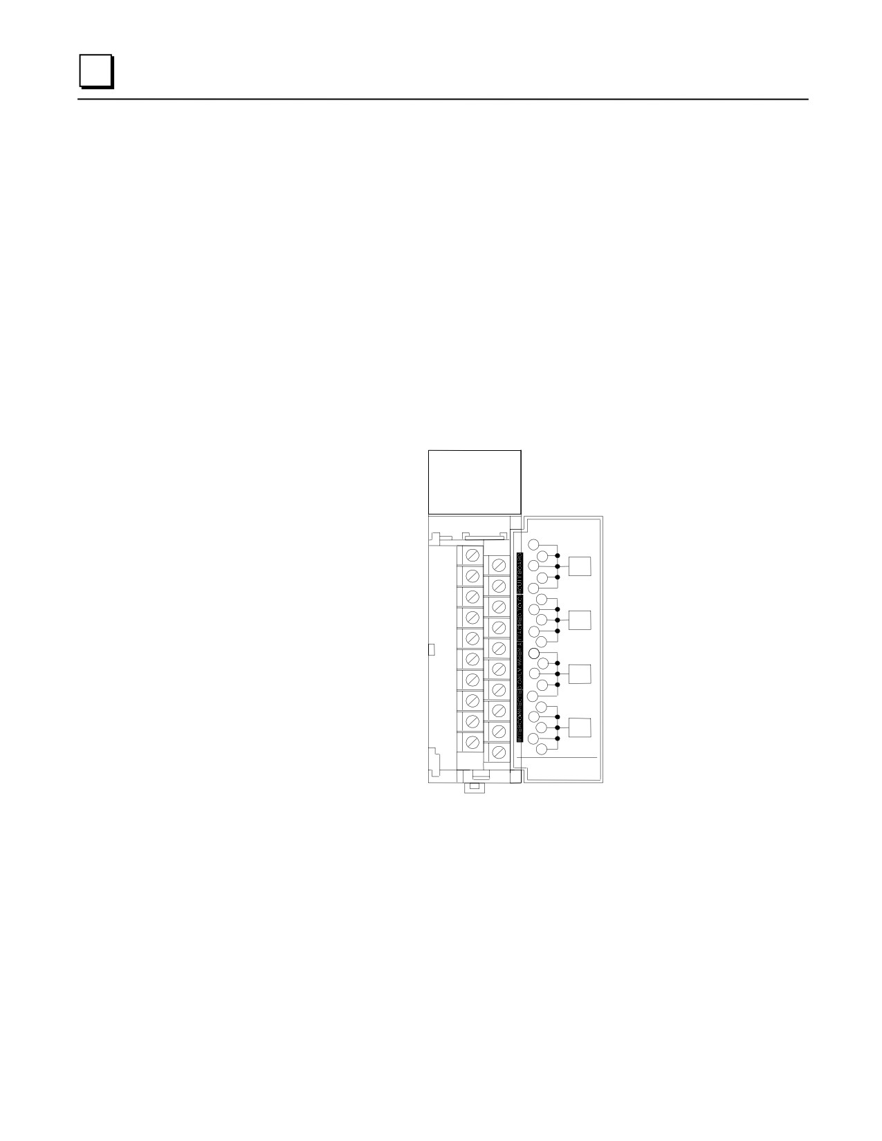
The Genius Communications Module (IC693CMM301) for the Series 90-30 PLC provides global
communications on a Genius Communications bus between Series 90-30 PLCs and/or other GE
Fanuc PLCs. Series 90-70, Series Six, and Series Five PLCs can communicate on this bus through
their respective Genius Bus Controllers.
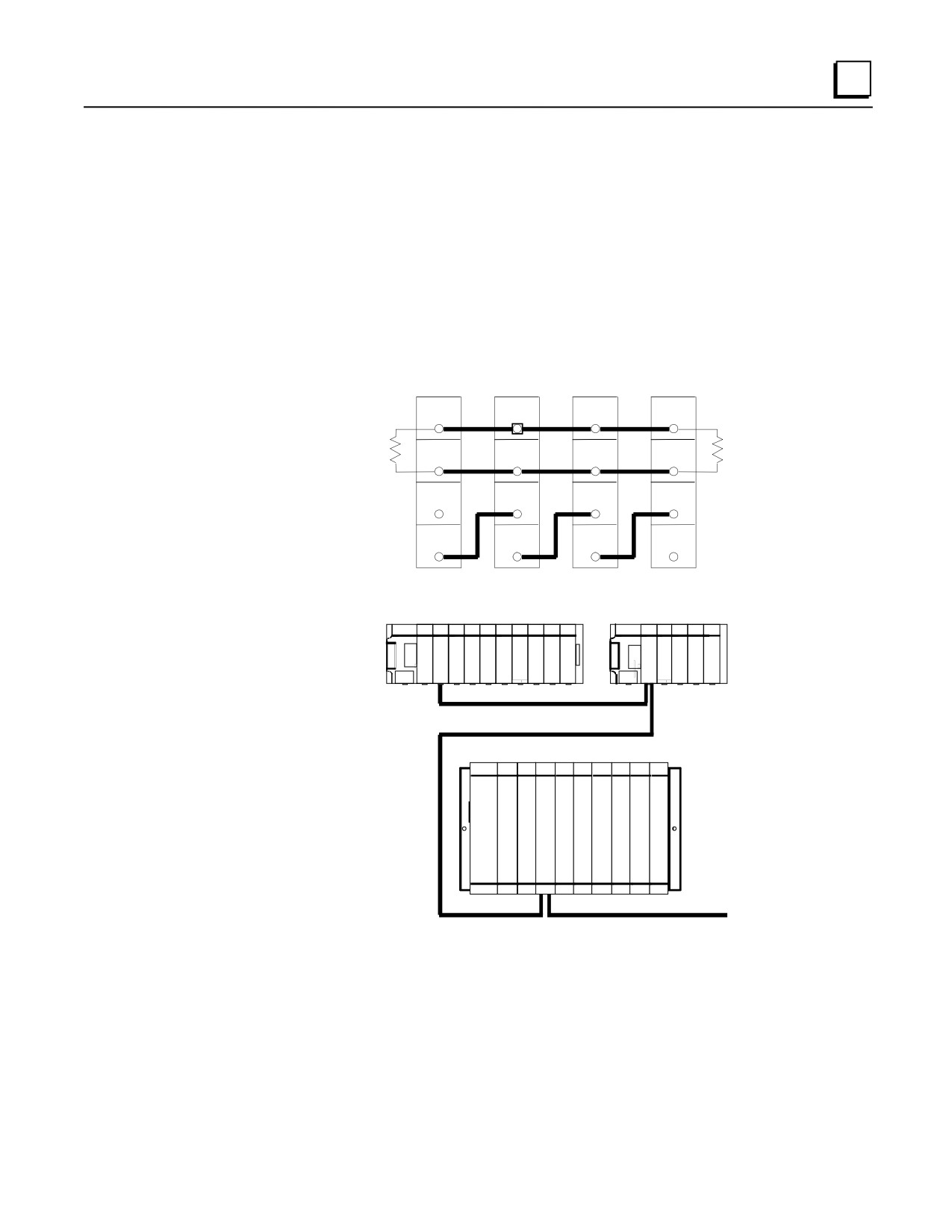
The Genius Communications bus is a token passing peer-to-peer, noise immune network optimized
to provide high speed transfer of real time control data. Up to eight Series 90-30 PLC CPUs, in
any combination, can communicate with each other over a single Genius I/O serial bus using a
standard twisted pair, shielded cable.
GENIUS
COMM
OK
COM
GENIUS
COMMUNICATIONS
MODULE
1
2
3
SER
1
4
5
6
7
8
SER
2
9
10
11
12
13
SHD
IN
14
15
16
17
18
SHD
OUT
19
20
44A729182-016R02
FOR USE WITH
IC693CMM301 / 302
Figure 8-1. The IC693CMM301 GCM Module
8-2
Series 90-30 PLC Installation and Hardware Manual - August 2002
GFK-0356Q
8
Status LEDs
The LEDs on the front of the GCM module indicate its operating status and should be on during
normal operation.
OK Shows the status of the GCM module. This LED turns on after power up diagnostics are
completed.
COM Shows the status of the Genius communications bus. This LED is on steadily when the bus
is operating properly. It blinks for intermittent bus errors and is off for a failed bus. It is
also off when no configuration has been received from the PLC CPU.
FIRST
LAST
DEVICE
DEVICE
SERIAL
SERIAL
SERIAL
SERIAL
1
1
1
1
R
SERIAL
SERIAL
SERIAL
SERIAL
R
2
2
2
2
SHIELD
SHIELD
SHIELD
SHIELD
IN
IN
IN
IN
SHIELD
SHIELD
SHIELD
SHIELD
OUT
OUT
OUT
OUT
Figure 8-2. Genius Bus Wiring Schematic
SERIES 90-30
SERIES 90-30
C
G
G
P
C
C
U
M
M
GENIUS COMMUNICATIONS BUS
SERIES 90-70
G
B
C
Figure 8-3. Example of Genius Communications Network
GCM Documentation
For detailed information on the Genius Communications Module, including installation
instructions, refer to GFK-0412, the Series 90-30 Genius Communications Module User’s Manual.
GFK-0356Q
Chapter 8 Option Modules
8-3
8
IC693CMM302 Enhanced Genius Communications Module (GCM+)
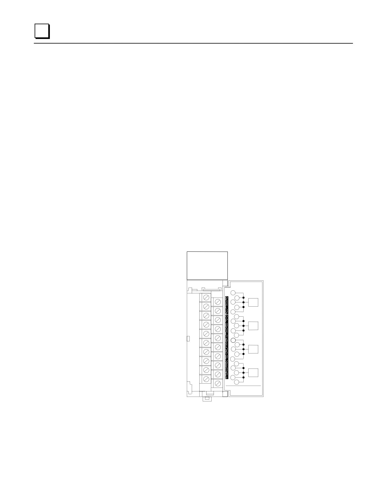
The Enhanced Genius Communications Module (GCM+), IC693CMM302, is an intelligent module
that provides automatic global data communications between a Series 90-30 PLC and up to 31
other devices on a Genius bus.
The GCM+ can be located in any standard Series 90-30 CPU baseplate, expansion baseplate, or
remote baseplate. However, for most efficient operation, it is recommended that the module be
installed in the CPU baseplate since the sweep impact time of the GCM+ module depends on the
model of PLC and the baseplate where it is located. Note: if a GCM module is present in a
system, GCM+ modules cannot be included in the system.
Multiple GCM+ modules can be installed in a Series 90-30 PLC system with each GCM+ having
its own Genius bus serving up to 31 additional devices on the bus. For example, this allows a
Series 90-30 PLC with three GCM+ modules to exchange global data with as many as 93 other
Genius devices automatically. In addition to basic global data exchange, the GCM+ module can be
used for various applications such as:
Data monitoring by a personal computer or an industrial computer.
Monitoring data from Genius I/O blocks (although it cannot control Genius I/O blocks).
Peer-to-peer communications among devices on the bus.
Master-slave communications among devices on the bus (emulates remote I/O).
The Genius bus connects to the terminal board on front of the GCM+ module.
ENHANCED
GENIUS
COMM
OK
COM
COMMUNICATIONS
MODULE
1
2
3
SER
1
4
5
6
7
SER
8
2
9
10
11
12
13
SHD
IN
14
15
16
17
18
SHD
OUT
19
20
44A729182-016R02
FOR USE WITH
IC693CMM301 / 302
Figure 8-4. Enhanced Genius Communications Module
8-4
Series 90-30 PLC Installation and Hardware Manual - August 2002
GFK-0356Q
8
Status LEDs
The LEDs on the front of the GBC indicate its operating status and should be on during normal
operation.
OK Shows the status of the GBC module. This LED turns on after power up diagnostics are
completed.
COM Shows the status of the Genius communications bus. This LED is on steadily when the bus
is operating properly. It blinks for intermittent bus errors and is off for a failed bus. It is
also off when no configuration has been received from the PLC CPU.
GCM+ Documentation
For more information about the GCM+, refer to GFK-0695, Series 90-30 Enhanced Genius
Communications Module User’s Guide.
GFK-0356Q
Chapter 8 Option Modules
8-5
8
IC693BEM331 Genius Bus Controller (GBC)
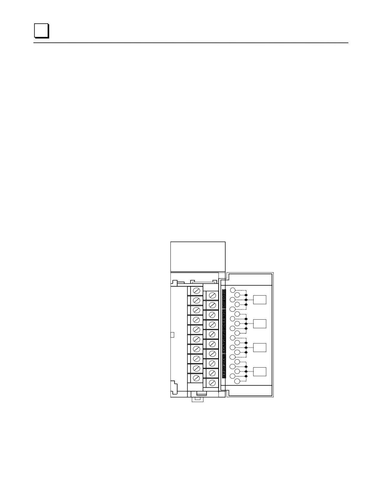
The Series 90-30 Genius Bus Controller (GBC), catalog number IC693BEM331, provides the
interface between a Series 90-30 PLC and a Genius I/O serial bus. The GBC receives and
transmits control data of up to 128 bytes for up to 31 devices on the Genius I/O bus. A Genius Bus
Controller can serve:
Genius blocks, which provide an interface to a wide range of discrete, analog, and special-
purpose field devices. Note that the GCM and GCM+ modules, described earlier, cannot
control Genius blocks.
Remote Drops, which consist of Series 90-70 I/O racks interfaced to the bus through Remote
I/O Scanner modules. Each of these drops can have any mix of Series 90-70 discrete and
analog I/O modules, providing up to 128 bytes of input data and 128 bytes of output data.
Field Control I/O Station, which consists of a Bus Interface Unit (BIU) and up to eight
additional Field Control modules. The BIU provides intelligent processing, I/O scanning, and
feature configuration for the I/O station.
Genius Hand-Held Monitor (HHM), which is a portable device that can also be permanently
mounted. The HHM provides a convenient operator interface for block setup, data monitoring,
and diagnostics.
Multiple hosts, for communications using datagrams and Global Data.
GENIUS
BUS
CONTROL
OK
COM
GENIUS
BUS
CONTROLLER
1
2
SER
3
1
4
5
6
7
SER
8
2
9
10
11
12
SHD
13
IN
14
15
16
17
SHD
18
OUT
19
20
44A729182-068R01
FOR USE WITH
IC693BEM331
Figure 8-5. Genius Bus Controller Module
A bus may feature I/O control, enhanced by communications commands in the program. Or, a bus
can be used entirely for I/O control, with many I/O devices and no additional communications. A
bus can also be dedicated to CPU communications, with multiple CPUs and no I/O devices. More
8-6
Series 90-30 PLC Installation and Hardware Manual - August 2002
GFK-0356Q
8
complex systems can also be developed, with dual CPUs and one or more additional CPUs for data
monitoring.
Number of Genius Bus Controllers
Up to eight Genius Bus Controllers or Enhanced Genius Communications Modules can be included
in a Series 90-30 PLC system that has release 5.0 or later CPU firmware. A GBC cannot be
installed in a system with a GCM.
The I/O devices on a bus may be Genius I/O blocks, or standard Series 90-70 I/O modules in one or
more remote drops. The total number of I/O circuits that can be served by one Genius bus depends
on the types of I/O devices that are used and the memory available in the CPU.
Many Genius I/O blocks have both inputs and outputs on the same block. Blocks configured in the
programming software as having both inputs and outputs occupy the identical number of references
in both %I and %Q memory, regardless of the block’s software configuration. Unused references
cannot be assigned to other inputs or outputs, and should not be used in the application program.
Status LEDs
The LEDs on the front of the GBC indicate its operating status and should be on during normal
operation.
OK Shows the status of the GBC module. This LED turns on after power up diagnostics are
completed.
COM Shows the status of the Genius communications bus. This LED is on steadily when the bus
is operating properly. It blinks for intermittent bus errors and is off for a failed bus. It is
also off when no configuration has been received from the PLC CPU.
Compatibility
Specific equipment or software versions required for compatibility with the GBC module are listed
below.
Series 90-30 PLC
CPU: The GBC module can be used with CPU models: IC693CPU311K, 321K, 331L or later, or
any version of the IC693CPU313, 323, 340, 341, 350, 351, 352, 360, 363, and 364. The CPU
firmware must be release 5.0 or later.
Logicmaster 90-30 version 5.0 (IC641SWP301L, 304J, 306F, 307F), VersaPro, or
Logic Developer-PLC software is required.
Series Six PLC
To exchange global data with a Genius Bus Controller, the Series Six Bus Controller must be
catalog number IC660CBB902F/903F (firmware version 1.5), or later.
GFK-0356Q
Chapter 8 Option Modules
8-7