FANUC Series 0i-MODEL D, Series 0i Mate-MODEL D. For Lathe System USER’S MANUAL - page 16
A.PARAMETERS
APPENDIX
B-64304EN-1/01
Grinding axis number of Oscillation Direct Fixed Dimension Grinding
5179
Cycle(G74)
[Input type]
Parameter input
[Data type]
Byte path
[Valid data range]
0 to Number of controlled axes
Set the Grinding axis number of Oscillation Direct Fixed Dimension
Grinding Cycle(G74).
NOTE
The axis number except for the cutting axis can be
specified. When the axis number which is same to
cutting axis is specified, PS0456 alarm is issued at
the time of execution. The Grinding Cycle is
executed when this parameter value is 0, PS0456
alarm is also issued.
#7
#6
#5
#4
#3
#2
#1
#0
5200
FHD
PCP
DOV
G84
[Input type]
Parameter input
[Data type]
Bit path
# 0
G84
Method for specifying rigid tapping:
0: An M code specifying the rigid tapping mode is specified prior to
the issue of the G84
(or G74) command.
(See parameter
No.5210).
1: An M code specifying the rigid tapping mode is not used. (G84
cannot be used as a G code for the tapping cycle; G74 cannot be
used for the reverse tapping cycle.)
# 4
DOV
Override during extraction in rigid tapping:
0: Invalidated
1: Validated (The override value is set in parameter No.5211. )
# 5
PCP
Address Q is specified in a tapping cycle/rigid tapping:
0: A high-speed peck tapping cycle is assumed.
1: A peck tapping cycle is assumed.
NOTE
In a tapping cycle, this parameter is valid when bit
6 (PCT) of parameter No. 5104 is 1. When bit 6
(PCT) of parameter No. 5104 is 0, a (high-speed)
peck tapping cycle is not assumed.
# 6
FHD
Feed hold and single block in rigid tapping:
0: Invalidated
1: Validated
- 434 -
B-64304EN-1/01
APPENDIX
A.PARAMETERS
#7
#6
#5
#4
#3
#2
#1
#0
5201
OV3
OVU
TDR
[Input type]
Parameter input
[Data type]
Bit path
# 2
TDR
Cutting time constant in rigid tapping:
0: Uses a same parameter during cutting and extraction (Parameter
Nos. 5261 through 5264)
1: Not use a same parameter during cutting and extraction
Parameter Nos. 5261 to 5264: Time constant during cutting
Parameter Nos. 5271 to 5274: Time constant during extraction
# 3
OVU
The increment unit of the override parameter (No.5211) for tool rigid
tapping extraction is:
0:
1%
1:
10%
# 4
OV3
A spindle speed for extraction is programmed, so override for
extraction operation is:
0: Disabled.
1: Enabled.
#7
#6
#5
#4
#3
#2
#1
#0
5202
OVE
[Input type]
Parameter input
[Data type]
Bit path
NOTE
When at least one of these parameters is set, the
power must be turned off before operation is
continued.
# 6
OVE
The specification range of extraction override command (address J) by
rigid tapping program specification is:
0:
100% to 200%.
1:
100% to 2000%.
NOTE
1 To enable the extraction override command
(address J) by program specification, set bit 4
(OV3) of parameter No.5201 to 1.
2 When this parameter is set to 1, the operation
equivalent to that of the FS0i-C is assumed.
- 435 -
A.PARAMETERS
APPENDIX
B-64304EN-1/01
#7
#6
#5
#4
#3
#2
#1
#0
5203
OVS
RFF
[Input type]
Parameter input
[Data type]
Bit path
# 2
RFF
In rigid tapping, feed forward is:
0: Disabled.
1: Enabled. (Recommended)
As the standard setting, set 1.
At the same time, set the parameter for the advanced preview feed
forward coefficient for the tapping axis and the parameter for the
advance preview feed forward coefficient for the spindle so that these
values match.
•
Advanced preview feed forward coefficient for the tapping axis:
Parameter No.2092
(or parameter No.2144 if the cutting/rapid traverse feed forward
function is enabled (bit 4 of parameter No.2214 is set to 1))
•
Advanced preview feed forward coefficient for the spindle:
Parameter No.4344
NOTE
This parameter is valid when a serial spindle is
used.
# 4
OVS
In rigid tapping, override by the feedrate override select signal and
cancellation of override by the override cancel signal is:
0: Disabled.
1: Enabled.
When feedrate override is enabled, extraction override is disabled.
The spindle override is clamped to
100% during rigid tapping,
regardless of the setting of this parameter.
#7
#6
#5
#4
#3
#2
#1
#0
RTX
5209
[Input type]
Parameter input
[Data type]
Bit path
# 0
RTX
In rigid tapping in a T series, the tapping axis is:
0: Selected by selecting a plane.
1: Always assumed to be the Z-axis for G84 or the X-axis for G88.
NOTE
This parameter becomes invalid when bit 1 (FCV)
of parameter No.0001 is set to 1, and rigid tapping
is specified using the Series10/11 format.
- 436 -
B-64304EN-1/01
APPENDIX
A.PARAMETERS
5211
Override value during rigid tapping extraction
[Input type]
Parameter input
[Data type]
Word path
[Unit of data]
1% or 10%
[Valid data range]
0 to 200
The parameter sets the override value during rigid tapping extraction.
NOTE
The override value is valid when bit 4 (DOV) of
parameter No.5200 is set to 1. When bit 3 (OVU) of
parameter No.5201 is set to 1, the unit of set data is
10%. An override of up to 200% can be applied to
extraction.
5213
Return or clearance in peck tapping cycle
[Input type]
Setting input
[Data type]
Real path
[Unit of data]
mm, inch (input unit)
[Minimum unit of data]
Depend on the increment system of the drilling axis
[Valid data range]
0 or positive 9 digit of minimum unit of data (refer to the standard
parameter setting table (B))
(When the increment system is IS-B, 0.0 to +999999.999)
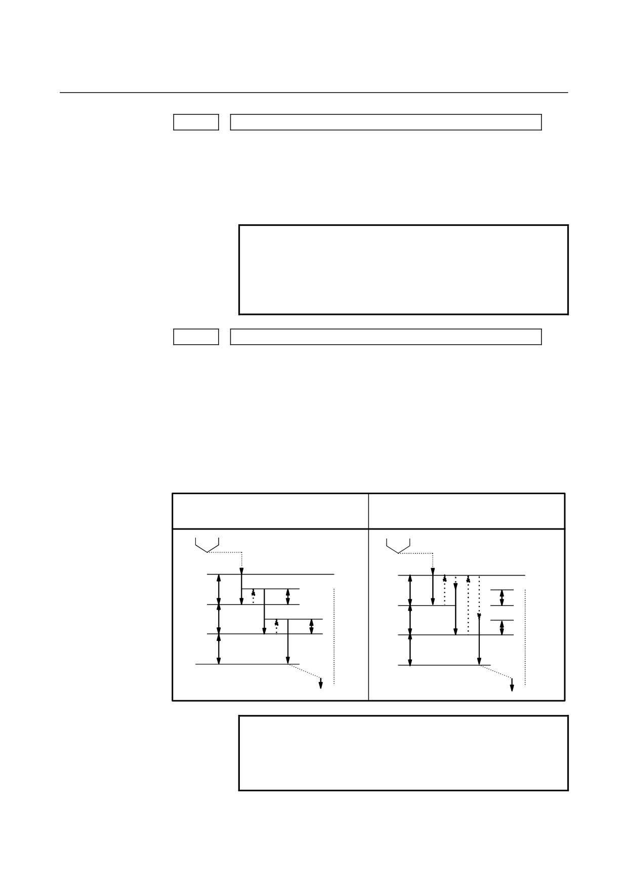
This parameter sets the escape value of a high-speed peck tapping
cycle or the clearance value of a peck tapping cycle.
When the parameter PCP (bit 5 of No.5200) is
When the parameter PCP (bit 5 of No.5200)
set to 0.
is set to 1.
q : Depth of cut
q : Depth of cut
d : Return value
d : Clearance value
R point
R point
q
q
d
d
q
q
d
d
q
q
Z point
Z point
NOTE
1 In a tapping cycle, this parameter is valid when bit
6 (PCT) of parameter No. 5104 is 1.
2 For the diameter axis, set this parameter using the
diameter value.
- 437 -
A.PARAMETERS
APPENDIX
B-64304EN-1/01
5241
Maximum spindle speed in rigid tapping (first gear)
5242
Maximum spindle speed in rigid tapping (second gear)
5243
Maximum spindle speed in rigid tapping (third gear)
5244
Maximum spindle speed in rigid tapping (fourth gear)
[Input type]
Parameter input
[Data type]
2-word spindle
[Unit of data]
min-1
[Valid data range]
0 to 9999
Spindle position coder gear ratio
1 : 1
0 to 7400
1 : 2
0 to 9999
1 : 4
0 to 9999
1 : 8
0 to 9999
Each of these parameters is used to set a maximum spindle speed for
each gear in rigid tapping.
Set the same value for both parameter No.5241 and parameter
No.5243 for a one-stage gear system. For a two-stage gear system, set
the same value as set in parameter No. 5242 in parameter No. 5243.
Otherwise, alarm PS0200 will be issued.
5321
Spindle backlash in rigid tapping (first-stage gear)
5322
Spindle backlash in rigid tapping (second-stage gear)
5323
Spindle backlash in rigid tapping (third-stage gear)
5324
Spindle backlash in rigid tapping (fourth-stage gear)
[Input type]
Parameter input
[Data type]
Word spindle
[Unit of data]
Detection unit
[Valid data range]
-9999 to 9999
Each of these parameters is used to set a spindle backlash.
#7
#6
#5
#4
#3
#2
#1
#0
5450
PLS
PDI
[Input type]
Parameter input
[Data type]
Bit path
# 0
PDI
When the second axis on the plane in the polar
coordinate
interpolation mode is based on radius specification:
0: Radius specification is used.
1: Diameter specification is used.
- 438 -

B-64304EN-1/01
APPENDIX
A.PARAMETERS
# 2
PLS
The polar coordinate interpolation shift function is:
0: Not used.
1: Used.
This enables machining using the workpiece coordinate system with a
desired point which is not the center of the rotation axis set as the
origin of the coordinate system in polar coordinate interpolation.
5460
Axis (linear axis) specification for polar coordinate interpolation
[Input type]
Parameter input
[Data type]
Byte path
[Valid data range]
1 to number of controlled axes
This parameter sets control axis numbers of linear axis to execute
polar interpolation.
5461
Axis (rotation axis) specification for polar coordinate interpolation
[Input type]
Parameter input
[Data type]
Byte path
[Valid data range]
1 to number of controlled axes
This parameter sets control axis numbers of rotation axis to execute
polar interpolation.
5463
Automatic override tolerance ratio for polar coordinate interpolation
[Input type]
Parameter input
[Data type]
Byte path
[Unit of data]
%
[Valid data range]
0 to 100
Typical setting: 90% (treated as 90% when set to 0)
Set the tolerance ratio of the fastest cutting feedrate to the speed of the
rotation axis during automatic override of polar coordinate
interpolation.
Compensation for error on hypothetical axis of polar coordinate
5464
interpolation
[Input type]
Parameter input
[Data type]
Byte path
[Unit of data]
mm, inch (input unit)
[Minimum unit of data]
Depend on the increment system of the reference axis
[Valid data range]
9 digit of minimum unit of data (refer to standard parameter setting
table (A))
(For IS-B, -999999.999 to +999999.999)
This parameter is used to set the error if the center of the rotation axis
on which polar coordinate interpolation is performed is not on the
X-axis.
If the setting of the parameter is
0, regular polar coordinate
interpolation is performed.
- 439 -
A.PARAMETERS
APPENDIX
B-64304EN-1/01
#7
#6
#5
#4
#3
#2
#1
#0
6000
HGO
MGO
[Input type]
Parameter input
[Data type]
Bit path
# 1
MGO
When a GOTO statement for specifying custom macro control is
executed, a high-speed branch to 20 sequence numbers executed from
the start of the program is:
0: A high-speed branch is not caused to n sequence numbers from
the start of the executed program.
1: A high-speed branch is caused to n sequence numbers from the
start of the program.
# 4
HGO
When a GOTO statement in a custom macro control command is
executed, a high-speed branch to the
30 sequence numbers
immediately before the executed statement is:
0: Not made.
1: Made.
#7
#6
#5
#4
#3
#2
#1
#0
6240
IGA
AE0
[Input type]
Parameter input
[Data type]
Bit path
NOTE
When at least one of these parameters is set, the
power must be turned off before operation is
continued.
# 0
AE0
Measurement position arrival is assumed when the automatic tool
compensation signals XAE1 and XAE2 <X004.0, 1> (T series) or the
automatic tool length measurement signals XAE1, XAE2, and XAE3
<X004.0, .1, .2> (M series) are:
0:
1.
1:
0.
# 7
IGA
Automatic tool compensation (T series) is:
0: Used.
1: Not used.
- 440 -
B-64304EN-1/01
APPENDIX
A.PARAMETERS
Feedrate during measurement of automatic tool compensation (T series) (for
6241
the XAE1 and GAE1 signals)
Feedrate during measurement of automatic tool compensation (T series) (for
6242
the XAE2 and GAE2 signals)
[Input type]
Parameter input
[Data type]
Real path
[Unit of data]
mm/min, inch/min, deg/min (machine unit)
[Minimum unit of data]
Depend on the increment system of the applied axis
[Valid data range]
Refer to the standard parameter setting table (C)
(When the increment system is IS-B, 0.0 to +999000.0)
These parameters set the relevant feedrate during measurement of
automatic tool compensation (T series) .
NOTE
When the setting of parameter No. 6242 or 6243 is
0, the setting of parameter No. 6241 is used.
6251
γ value on the X axis during automatic tool compensation (T series)
6252
γ value on the Z axis during automatic tool compensation (T series)
[Input type]
Parameter input
[Data type]
2-word path
[Unit of data]
mm, inch, deg (machine unit)
[Minimum unit of data]
Depend on the increment system of the applied axis
[Valid data range]
9 digit of minimum unit of data (refer to standard parameter setting
table (A))
(When the increment system is IS-B, -999999.999 to +999999.999)
These parameters set the relevant γ value during automatic tool
compensation (T series).
NOTE
Set a radius value regardless of whether diameter
or radius programming is specified.
- 441 -
A.PARAMETERS
APPENDIX
B-64304EN-1/01
6254
ε value on the X axis during automatic tool compensation (T series)
6255
ε value on the Z axis during automatic tool compensation (T series)
[Input type]
Parameter input
[Data type]
2-word path
[Unit of data]
mm, inch, deg (machine unit)
[Minimum unit of data]
Depend on the increment system of the applied axis
[Valid data range]
9 digit of minimum unit of data (refer to standard parameter setting
table (A))
(When the increment system is IS-B, -999999.999 to +999999.999)
These parameters set the relevant ε value during automatic
tool
compensation (T series).
NOTE
Set a radius value regardless of whether
diameter or radius programming is specified.
#7
#6
#5
#4
#3
#2
#1
#0
8103
MWT
[Input type]
Parameter input
[Data type]
Bit
NOTE
When this parameter is set, the power must be
turned off before operation is continued.
# 0
MWT
As the signal interface for the waiting M code:
0: The path individual signal interface is used.
1: The path common signal interface is used.
This parameter can be selected only when 2-path control is used.
8110
Waiting M code range (minimum value)
8111
Waiting M code range (maximum value)
[Input type]
Parameter input
[Data type]
2-word
[Valid data range]
0 ,100 to 99999999
A range of M code values can be set by specifying a minimum waiting
M coder value (parameter No. 8110) and a maximum waiting M code
value (parameter No. 8111).
(parameter No. 8110) ≤ (waiting M code) ≤ (parameter No. 8111)
Set 0 in these parameters when the waiting M code is not used.
- 442 -
B-64304EN-1/01
APPENDIX
A.PARAMETERS
#7
#6
#5
#4
#3
#2
#1
#0
8132
YOF
NOTE
When at least one of these parameters is set, the
power must be turned off before operation is
continued.
[Input type]
Parameter input
[Data type]
Bit
# 1
YOF
Y-axis offset is:
0: Not Used.
1: Used.
#7
#6
#5
#4
#3
#2
#1
#0
8133
MSP
SSC
NOTE
When at least one of these parameters is set, the
power must be turned off before operation is
continued.
[Input type]
Parameter input
[Data type]
Bit
# 0
SSC
Constant surface speed control is:
0: Not Used.
1: Used.
# 3
MSP
Multi-spindle is:
0: Not Used.
1: Used.
- 443 -
A.PARAMETERS
APPENDIX
B-64304EN-1/01
#7
#6
#5
#4
#3
#2
#1
#0
8134
CCR
BAR
NOTE
When at least one of these parameters is set, the
power must be turned off before operation is
continued.
[Input type]
Parameter input
[Data type]
Bit
# 1
BAR
Chuck and tail stock barrier function (T series) is:
0: Not Used.
1: Used.
NOTE
1 The chuck and tail stock barrier function is provided
only for the T series.
2 When the chuck and tail stock barrier function is
selected, stored stroke limits 2 and 3 cannot be
used.
That is, this parameter also specifies whether to use stored stroke
limits 2 and 3 as shown below.
BAR
Stored stroke limits 2 and 3 are:
0: Used.
1: Not Used.
# 2
CCR
Chamfering / corner R is:
0: Not Used.
1: Used.
#7
#6
#5
#4
#3
#2
#1
#0
8136
NGW
NOTE
When at least one of these parameters is set, the
power must be turned off before operation is
continued.
[Input type]
Parameter input
[Data type]
Bit
# 6
NGW
Tool geometry/wear compensation (T series) is:
0: Used.
1: Not Used.
- 444 -
B-64304EN-1/01
APPENDIX
A.PARAMETERS
#7
#6
#5
#4
#3
#2
#1
#0
19607
NAA
CAV
CCC
[Input type]
Parameter input
[Data type]
Bit path
# 2
CCC
In the cutter compensation/tool nose radius compensation mode, the
outer corner connection method is based on:
0: Linear connection type.
1: Circular connection type.
# 5
CAV
When an interference check finds that interference
(overcutting)
occurred:
0: Machining stops with the alarm (PS0041).
(Interference check alarm function)
1: Machining is continued by changing the tool path to prevent
interference
(overcutting) from occurring.
(Interference check
avoidance function)
For the interference check method, see the descriptions of bit 1 (CNC)
of parameter No. 5008 and bit 3 (CNV) of parameter No. 5008.
# 6
NAA
When the interference check avoidance function considers that an
avoidance operation is dangerous or that a further interference to the
interference avoidance vector occurs:
0: An alarm is issued.
When an avoidance operation is considered to be dangerous, the
alarm (PS5447) is issued.
When a further interference to the interference avoidance vector
is considered to occur, the alarm (PS5448) is issued.
1: No alarm is issued, and the avoidance operation is continued.
CAUTION
When this parameter is set to 1, the path may be
shifted largely. Therefore, set this parameter to 0
unless special reasons are present.
- 445 -
A.PARAMETERS
APPENDIX
B-64304EN-1/01
Number of blocks to be read in the cutter compensation/tool nose radius
19625
compensation mode
[Input type] Setting input
[Data type] Byte path
[Valid data range]
3 to 8
This parameter sets the number of blocks to be read in the cutter
compensation/tool nose radius compensation mode. When a value less
than 3 is set, the specification of 3 is assumed. When a value greater
than 8 is set, the specification of 8 is assumed. As a greater number of
blocks are read, an overcutting (interference) forecast can be made
with a command farther ahead. However, the number of blocks read
and analyzed increases, so that a longer block processing time
becomes necessary.
Even if the setting of this parameter is modified in the MDI mode by
stopping in the cutter compensation/tool nose radius compensation
mode, the setting does not become valid immediately. Before the new
setting of this parameter can become valid, the cutter
compensation/tool noise radius compensation mode must be canceled,
then the mode must be entered again.
- 446 -

B-64304EN-1/01
APPENDIX
A.PARAMETERS
A.2
DATA TYPE
Parameters are classified by data type as follows:
Data type
Valid data range
Remarks
Bit
Bit machine group
Bit path
0 or 1
Bit axis
Bit spindle
Byte
Byte machine group
-128 to 127
Some parameters handle
Byte path
0 to 255
these types of data as
Byte axis
unsigned data.
Byte spindle
Word
Word machine group
Some parameters handle
-32768 to 32767
Word path
these types of data as
0 to 65535
unsigned data.
Word axis
Word spindle
2-word
2-word machine group
Some parameters handle
2-word path
0 to ±999999999
these types of data as
unsigned data.
2-word axis
2-word spindle
Real
Real machine group
See the Standard
Real path
Parameter Setting
Tables.
Real axis
Real spindle
NOTE
1 Each of the parameters of the bit, bit machine group, bit path, bit axis, and bit
spindle types consists of 8 bits for one data number (parameters with eight different
meanings).
2 For machine group types, parameters corresponding to the maximum number of
machine groups are present, so that independent data can be set for each machine
group.
3 For path types, parameters corresponding to the maximum number of paths are
present, so that independent data can be set for each path.
4 For axis types, parameters corresponding to the maximum number of control axes
are present, so that independent data can be set for each control axis.
5 For spindle types, parameters corresponding to the maximum number of spindles
are present, so that independent data can be set for each spindle axis.
6 The valid data range for each data type indicates a general range. The range varies
according to the parameters. For the valid data range of a specific parameter, see
the explanation of the parameter.
- 447 -
A.PARAMETERS
APPENDIX
B-64304EN-1/01
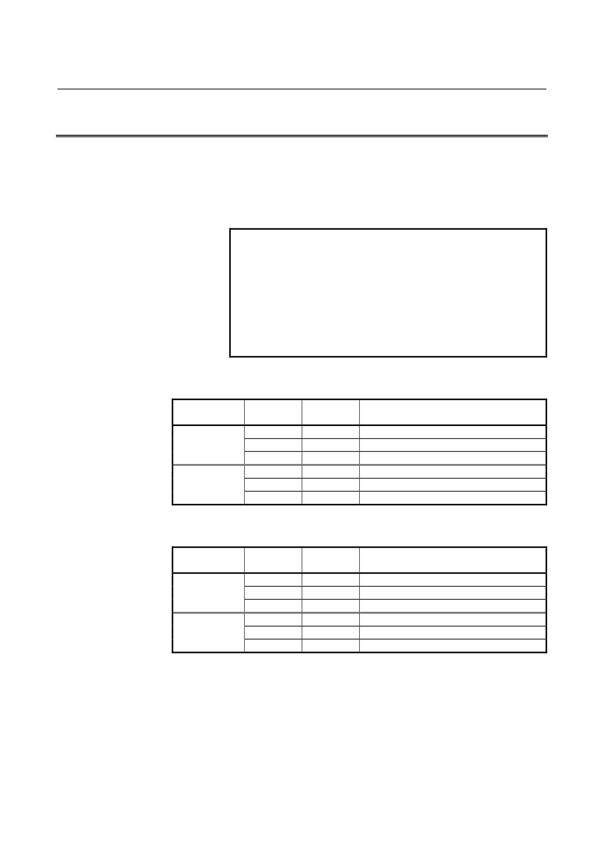
A.3 STANDARD PARAMETER SETTING TABLES
This section defines the standard minimum data units and valid data
ranges of the CNC parameters of the real type, real machine group
type, real path type, real axis type, and real spindle type. The data type
and unit of data of each parameter conform to the specifications of
each function.
NOTE
1 Values are rounded up or down to the nearest
multiples of the minimum data unit.
2 A valid data range means data input limits, and
may differ from values representing actual
performance.
3 For information on the ranges of commands to the
CNC, refer to Appendix D, "Range of Command
Value."
(A) Length and angle parameters (type 1)
Increment
Minimum
Unit of data
Valid data range
system
data unit
IS-A
0.01
-999999.99
to +999999.99
mm
IS-B
0.001
-999999.999
to +999999.999
deg.
IS-C
0.0001
-99999.9999
to
+99999.9999
IS-A
0.001
-99999.999
to
+99999.999
inch
IS-B
0.0001
-99999.9999
to
+99999.9999
IS-C
0.00001
-9999.99999
to
+9999.99999
(B) Length and angle parameters (type 2)
Increment
Minimum
Unit of data
Valid data range
system
data unit
IS-A
0.01
0.00
to +999999.99
mm
IS-B
0.001
0.000
to +999999.999
deg.
IS-C
0.0001
0.0000
to
+99999.9999
IS-A
0.001
0.000
to
+99999.999
inch
IS-B
0.0001
0.0000
to
+99999.9999
IS-C
0.00001
0.00000
to
+9999.99999
- 448 -
B-64304EN-1/01
APPENDIX
A.PARAMETERS
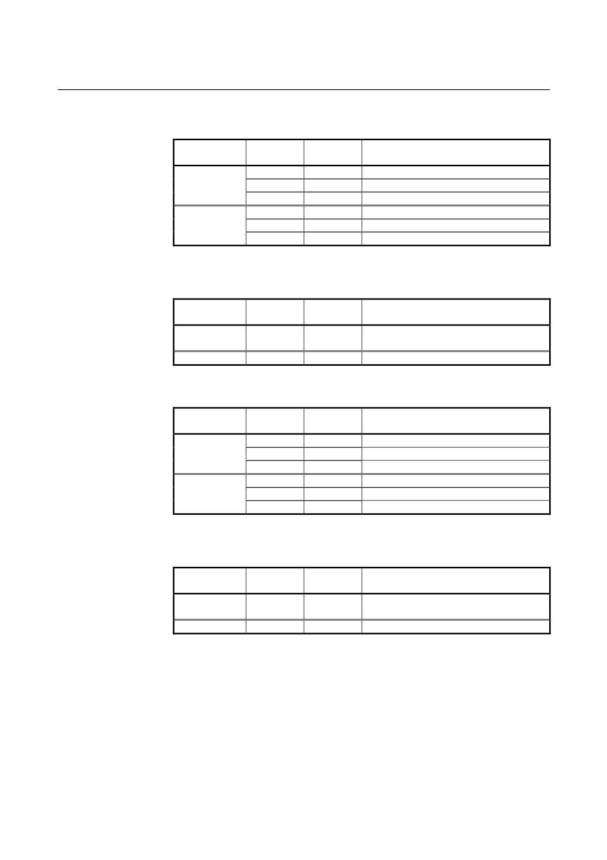
(C) Velocity and angular velocity parameters
Increment
Minimum
Unit of data
Valid data range
system
data unit
IS-A
0.01
0.0 to
+999000.00
mm/min
IS-B
0.001
0.0 to
+999000.000
degree/min
IS-C
0.0001
0.0 to
+99999.9999
IS-A
0.001
0.0 to
+96000.000
inch/min
IS-B
0.0001
0.0 to
+9600.0000
IS-C
0.00001
0.0 to
+4000.00000
If bit 7 (IESP) of parameter No. 1013 is set to 1, the valid data ranges
for IS-C are extended as follows:
Increment
Minimum
Unit of data
Valid data range
system
data unit
mm/min
IS-C
0.001
0.000 to +999000.000
degree/min
inch/min
IS-C
0.0001
0.0000 to +9600.0000
(D)Acceleration and angular acceleration parameters
Increment
Minimum
Unit of data
Valid data range
system
data unit
IS-A
0.01
0.00
to +999999.99
mm/sec2
IS-B
0.001
0.000
to +999999.999
deg./sec2
IS-C
0.0001
0.0000
to
+99999.9999
IS-A
0.001
0.000
to
+99999.999
inch/sec
2
IS-B
0.0001
0.0000
to
+99999.9999
IS-C
0.00001
0.00000
to
+9999.99999
If bit 7 (IESP) of parameter No. 1013 is set to 1, the valid data ranges
for IS-C are extended as follows:
Increment
Minimum
Unit of data
Valid data range
system
data unit
mm/min
IS-C
0.001
0.000 to +999999.999
degree/min
inch/min
IS-C
0.0001
0.0000 to +99999.9999
- 449 -
B.DIFFERENCES FROM SERIES 0i-C APPENDIX
B-64304EN-1/01
B
DIFFERENCES FROM SERIES 0i-C
Appendix B, "Differences from Series 0i-C", consists of the following
sections:
B.1
SETTING UNIT
452
B.2
AUTOMATIC TOOL OFFSET
453
B.3
CIRCULAR INTERPOLATION
455
B.4
HELICAL INTERPOLATION
456
B.5
SKIP FUNCTION
457
B.6
MANUAL REFERENCE POSITION RETURN
459
B.7
WORKPIECE COORDINATE SYSTEM
461
B.8
LOCAL COORDINATE SYSTEM
462
B.9
Cs CONTOUR CONTROL
464
B.10
MULTI-SPINDLE CONTROL
465
B.11
SERIAL/ANALOG SPINDLE CONTROL
466
B.12
CONSTANT SURFACE SPEED CONTROL
467
B.13
SPINDLE POSITIONING
468
B.14
TOOL FUNCTIONS
470
B.15
TOOL COMPENSATION MEMORY
471
B.16
INPUT OF TOOL OFFSET VALUE MEASURED B
473
B.17
CUSTOM MACRO
474
B.18
INTERRUPTION TYPE CUSTOM MACRO
477
B.19
PROGRAMMABLE PARAMETER INPUT (G10)
478
B.20
ADVANCED PREVIEW CONTROL
479
B.21
MACHINING CONDITION SELECTION FUNCTION
481
B.22
AXIS SYNCHRONOUS CONTROL
482
B.23
ARBITRARY ANGULAR AXIS CONTROL
487
B.24
RUN HOUR AND PARTS COUNT DISPLAY
488
B.25
MANUAL HANDLE FEED
489
B.26
PMC AXIS CONTROL
491
B.27
EXTERNAL SUBPROGRAM CALL (M198)
496
B.28
SEQUENCE NUMBER SEARCH
497
B.29
STORED STROKE CHECK
498
B.30
STORED PITCH ERROR COMPENSATION
500
B.31
SCREEN ERASURE FUNCTION AND AUTOMATIC
SCREEN ERASURE FUNCTION
501
B.32
RESET AND REWIND
502
B.33
MANUAL ABSOLUTE ON AND OFF
503
B.34
MEMORY PROTECTION SIGNAL FOR CNC
PARAMETER
504
B.35
EXTERNAL DATA INPUT
505
B.36
DATA SERVER FUNCTION
507
B.37
POWER MATE CNC MANAGER
508
B.38
CHUCK/TAIL STOCK BARRIER
509
- 450 -
B-64304EN-1/01
APPENDIX B.DIFFERENCES FROM SERIES 0i-C
B.39 THREADING CYCLE RETRACT (CANNED CUTTING
CYCLE/MULTIPLE REPETITIVE CANNED CUTTING
CYCLE)
510
B.40 POLAR COORDINATE INTERPOLATION
511
B.41 PATH INTERFERENCE CHECK (2-PATH CONTROL)
513
B.42 SYNCHRONOUS CONTROL AND COMPOSITE
CONTROL(2-PATH CONTROL)
514
B.43 SUPERIMPOSED CONTROL (2-PATH CONTROL)
519
B.44 Y AXIS OFFSET
521
B.45 CUTTER COMPENSATION/TOOL NOSE RADIUS
COMPENSATION
522
B.46 CANNED CYCLE FOR DRILLING
528
B.47 CANNED CYCLE /MULTIPLE REPETITIVE CANNED
CYCLE
530
B.48 CANNED GRINDING CYCLE
531
B.49 MULTIPLE RESPECTIVE CANNED CYCLE FOR
TURNING
532
B.50 CHAMFERING AND CORNER ROUNDING
537
B.51 DIRECT DRAWING DIMENSIONS PROGRAMMING
538
- 451 -

B.DIFFERENCES FROM SERIES 0i-C APPENDIX
B-64304EN-1/01
B.1 SETTING UNIT
B.1.1 Differences in Specifications
Function
Explanation
Diameter/radius
-
Make a selection using bit 3 (DIAx) of parameter No. 1006.
specification in the
move command for
Bit 3 (DIAx) of parameter No. 1006
each axis
The move command for each axis specifies:
0: Radius.
1: Diameter.
With Series 0i-C, in order for an axis whose diameter is specified to travel the specified
distance, it is necessary not only to set 1 in bit 3 (DIAx) of parameter No. 1006 but also to
make either of the following two changes:
-
Reduce the command multiplier (CMR) to half.
(The detection unit does not need to
be changed.)
-
Reduce the detection unit to half, and double the flexible feed gear (DMR).
With Series 0i-D, by contrast, just setting 1 in bit 3 (DIAx) of parameter No. 1006 causes
the CNC to reduce the command pulses to half, eliminating the need to make the
changes described above (when the detection unit is not changed).
Note that, when the detection unit is reduced to half, both the CMR and DMR need to be
doubled.
B.1.2 Differences in Diagnosis Display
None.
- 452 -

B-64304EN-1/01
APPENDIX B.DIFFERENCES FROM SERIES 0i-C
B.2 AUTOMATIC TOOL OFFSET
B.2.1 Differences in Specifications
Function
Series 0i-C
Series 0i-D
Operation of the
-
Added to the current offset.
-
Select whether to add or subtract, by
current offset for the
using bit 6 (MDC) of parameter No.
measurement result
6210.
Bit 6 (MDC) of parameter No. 6210
The measurement result of automatic tool
length measurement (system M) or
automatic tool compensation (system T) is:
0: Added to the current offset.
1: Subtracted from the current offset.
Setting of the feedrate
-
Set the value in parameter No. 6241.
-
Parameter No. 6241
for measurement
This is a parameter common to the
This is a parameter for the measuring
measuring position reached signals
position reached signals (XAE1 and
(XAE and ZAE).
GAE1).
-
Parameter No. 6242
This is a parameter for the measuring
position reached signals (XAE2 and
GAE2).
NOTE
When 0 is set in parameter No. 6242, the
value in parameter No. 6241 becomes
valid.
Setting of the γ value
-
Set the value in parameter No. 6251.
-
Parameter No. 6251
for the X axis
This is a parameter common to the
This is a parameter for the measuring
measuring position reached signals
position reached signals (XAE1 and
(XAE and ZAE).
GAE1).
-
Parameter No. 6252
This is a parameter for the measuring
position reached signals (XAE2 and
GAE2).
NOTE
When 0 is set in parameter No. 6252, the
value in parameter No. 6251 becomes
valid.
Setting of the ε value
-
Set the value in parameter No. 6254.
-
Parameter No. 6254
for the X axis
This is a parameter common to the
This is a parameter for the measuring
measuring position reached signals
position reached signals (XAE1 and
(XAE and ZAE).
GAE1).
-
Parameter No. 6255
This is a parameter for the measuring
position reached signals (XAE2 and
GAE2).
NOTE
When 0 is set in parameter No. 6255, the
value in parameter No. 6254 becomes
valid.
- 453 -
B.DIFFERENCES FROM SERIES 0i-C APPENDIX
B-64304EN-1/01
B.2.2 Differences in Diagnosis Display
None.
- 454 -
B-64304EN-1/01
APPENDIX B.DIFFERENCES FROM SERIES 0i-C
B.3 CIRCULAR INTERPOLATION
B.3.1 Differences in Specifications
Function
Series 0i-C
Series 0i-D
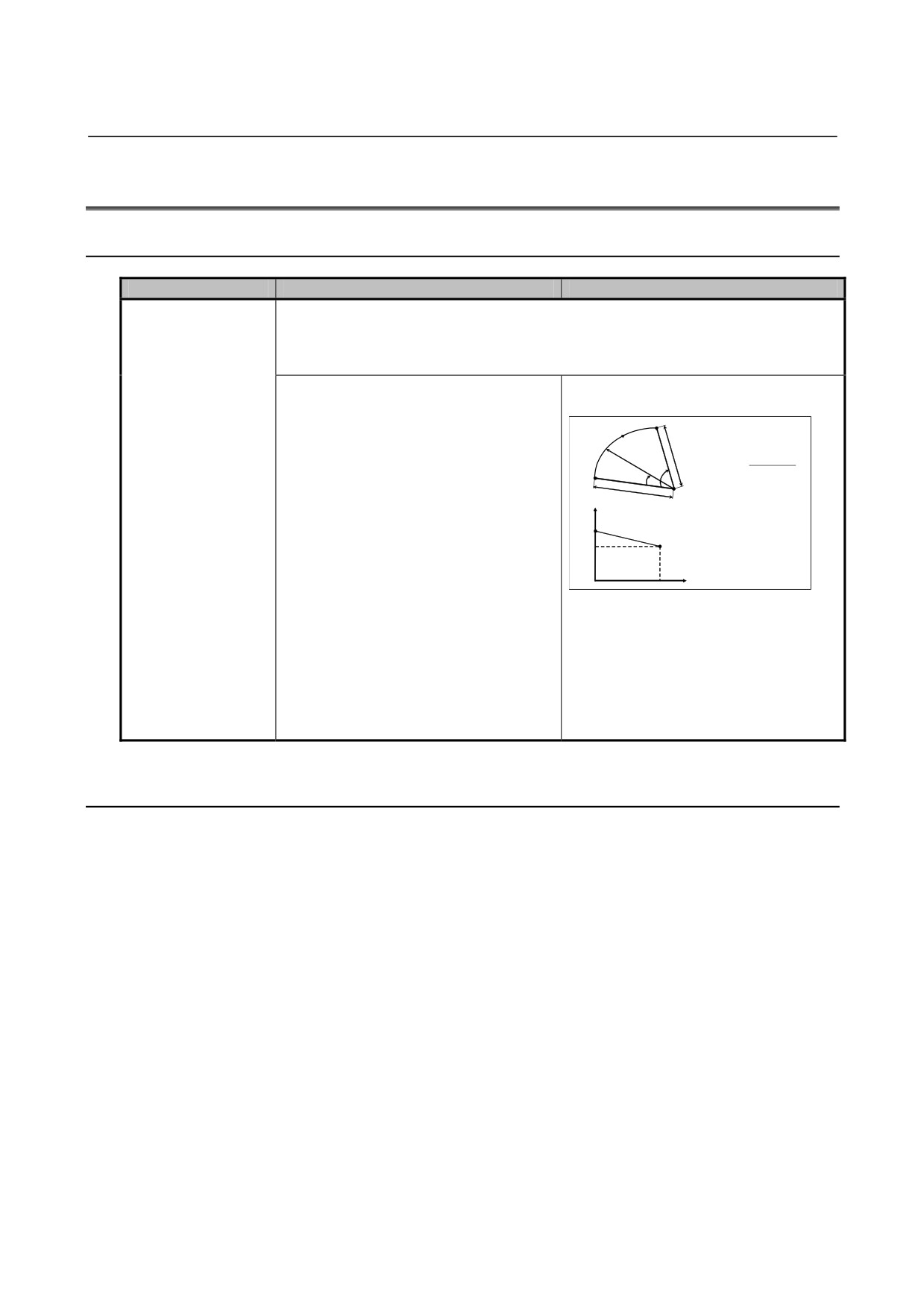
Interpolation method
If the difference between the radius values of the start point and end point of an arc is
when the arc end
greater than the value set in parameter No. 3410, alarm PS0020 is issued. If the
point is not on the arc
difference is smaller (the end point is not on the arc), circular interpolation is performed
as follows.
-
Circular interpolation is performed using
-
Helical interpolation is performed as
the radius value of the start point and,
shown in the figure below.
End point
when an axis reaches the end point, it is
moved linearly.
γe
γ(t)
(γe
−γs)θ
(t
)
γ(t)
=γs
+
Start
θ
θ
θ(t)
Parameter No. 3410
point
γs
中心
In a circular interpolation command, set the
Radius
limit allowed for the difference between the
Start point
γs
radius values of the start point and end
γe
End point
point.
Center θ
θ
In other words, the radius of the arc moves
linearly according to the center angle θ(t).
Specifying an arc where the arc radius of
the start point differs from that of the end
point enables helical interpolation. When
performing helical interpolation, set a large
value in parameter No. 3410 that specifies
the limit for the arc radius difference.
B.3.2 Differences in Diagnosis Display
None.
- 455 -
B.DIFFERENCES FROM SERIES 0i-C APPENDIX
B-64304EN-1/01
B.4 HELICAL INTERPOLATION
B.4.1 Differences in Specifications
Function
Series 0i-C
Series 0i-D
Specification of the
-
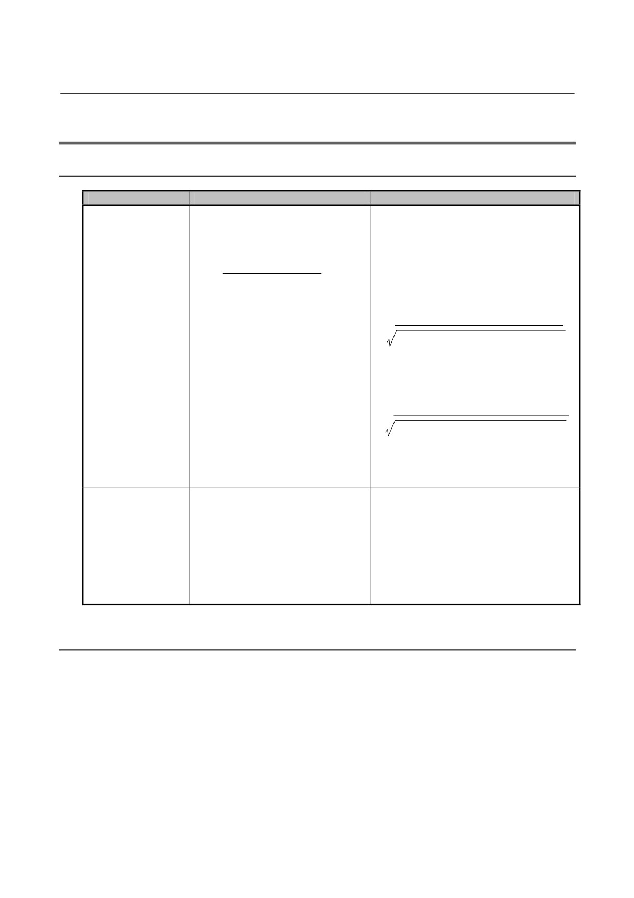
Specify the feedrate along a circular
-
Make a selection using bit 5 (HTG) of
feedrate
arc. Therefore, the feedrate of the
parameter No. 1403.
linear axis is as follows:
0: Same as left.
1: Specify a feedrate along the tool path
Length of linear axis
including the linear axis. Therefore, the
F ×
tangential velocity of the arc is expressed
Length of circular arc
as follows:
Length of arc
F×
(Length of arc)2+(Length of linear axis)2
The velocity along the linear axis is expressed
as follows:
Length of linear axis
F×
(Length of arc)2+(Length of linear axis)2
For details, refer to "HELICAL
INTERPOLATION" in "CONNECTION
MANUAL (FUNCTION)" (B-64303EN-1).
Helical cutting
-
Make a selection using bit 0 (HFC)
-
Bit 0 (HFC) of parameter No. 1404 is not
feedrate clamp
of parameter No. 1404.
available.
0: The feedrate of the arc and
The feedrate of the arc and linear axes is
linear axes is clamped by
clamped by parameter No. 1430.
parameter No. 1422 or No.1430.
1: The combined feedrate along
the tool path including the linear
axis is clamped by parameter
No. 1422.
B.4.2 Differences in Diagnosis Display
None.
- 456 -
B-64304EN-1/01
APPENDIX B.DIFFERENCES FROM SERIES 0i-C
B.5 SKIP FUNCTION
B.5.1 Differences in Specifications
Function
Series 0i-C
Series 0i-D
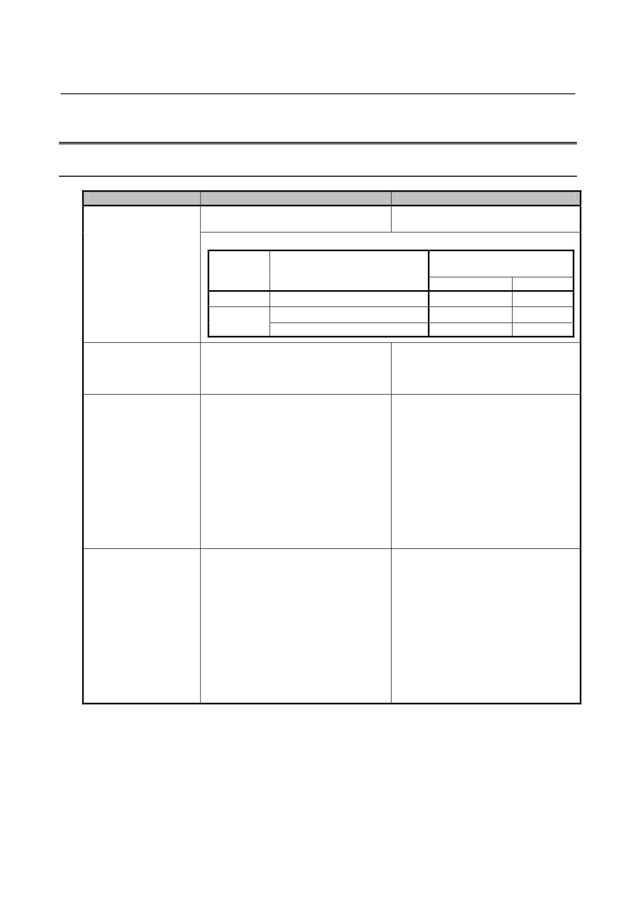
Setting to enable the
-
Set 1 in bit 5 (SLS) of parameter No.
-
Set 1 in bit 4 (HSS) of parameter No.
high-speed skip signal
6200.
6200.
for normal skip (G31)
when the multi-stage
Multi-stage
Parameter to decide on use
skip function is enabled
skip
Command
of the high-speed skip signal
function
FS0i-C
FS0i-D
Disabled
G31 (normal skip)
HSS
HSS
G31 (normal skip)
SLS
HSS
Enabled
G31P1 to G31P4 (multi-stage skip)
SLS
SLS
Target of
-
Compensation is performed for the
-
Compensation is performed for the
acceleration/deceleration
skip coordinates obtained when the
skip coordinates obtained when the
and servo system delay
high-speed skip signal is set to "1".
skip or high-speed skip signal is set to
compensation
"1".
Method of
-
There are two ways to perform
-
Bit 0 (SEA) of parameter No. 6201 is
acceleration/deceleration
compensation, as follows.
not available.
and servo system delay
[Compensating the value calculated
There is only one way to perform
compensation
from the cutting constant and servo
compensation, as follows.
constant]
[Compensating the accumulated
Set 1 in bit 0 (SEA) of parameter No.
pulses and positional deviation due to
6201.
acceleration/deceleration]
[Compensating the accumulated
Set 1 in bit 1 (SEB) of parameter No.
pulses and positional deviation due to
6201.
acceleration/deceleration]
Set 1 in bit 1 (SEB) of parameter No.
6201.
Skip cutting feedrate
-
Feedrate specified by the F code in
-
Depends on bit 1 (SFP) of parameter
(normal skip)
the program
No. 6207. When 0 is set, the
processing is the same as Series
0i-C.
Bit 1 (SFP) of parameter No. 6207
The feedrate during the skip function
(G31) is:
0: Feedrate specified by the F code in
the program.
1: Feedrate specified in parameter No.
6281.
- 457 -

B.DIFFERENCES FROM SERIES 0i-C APPENDIX
B-64304EN-1/01
Function
Series 0i-C
Series 0i-D
Skip cutting feedrate
-
Feedrate specified by the F code in
-
Depends on bit 2 (SFN) of parameter
(skip using the
the program
No. 6207. When 0 is set, the
high-speed skip signal or
processing is the same as Series
multi-step skip)
0i-C.
Bit 2 (SFP) of parameter No. 6207
When the skip function using the
high-speed skip signal (1 is set in bit 4
(HSS) of parameter No. 6200) or the
multi-step skip function is executed, the
feedrate is:
0: Feedrate specified by the F code in
the program.
1: Feedrate specified in parameter Nos.
6282 to 6285.
Axis to monitor to check
-
Depends on bit 3 (TSA) of parameter
-
Bit 3 (TSA) of parameter No. 6201 is
whether the torque limit
No. 6201.
not available.
has been reached
Only the axis specified in the same
(torque limit skip)
Bit 3 (TSA) of parameter No. 6201
block as G31 P99/98 is monitored.
To check whether the torque limit has
been reached, the torque limit skip
function (G31 P99/98) monitors:
0: All axes.
1: Only the axis specified in the same
block as G31 P99/98.
High-speed skip signal
As the skip signal for the G31 P99 command, the high-speed skip signal:
input for the G31 P99
-
Cannot be input.
-
Can be input.
command
(torque limit skip)
Setting of a positional
-
No parameter is available dedicated to
-
The value can be set in parameter No.
deviation limit in the
setting a positional deviation limit for
6287.
torque limit skip
the torque limit skip function.
command
Parameter No. 6287
(torque limit skip)
Set a positional deviation limit in the
torque limit skip command for each axis.
When G31 P99/98 is
-
The G31 P99/98 command is
-
Alarm PS0035 is issued.
specified without a
executed as is.
torque limit being
(No alarm is issued.)
specified in advance
(torque limit skip)
B.5.2 Differences in Diagnosis Display
None.
- 458 -

B-64304EN-1/01
APPENDIX B.DIFFERENCES FROM SERIES 0i-C
B.6 MANUAL REFERENCE POSITION RETURN
B.6.1 Differences in Specifications
Function
Series 0i-C
Series 0i-D
Conditions for
Manual reference position return is performed when automatic operation is halted (feed
performing manual
hold) and when any of the following conditions is met:
reference position
<Conditions>
return during feed
(1) Travel distance is remaining.
hold
(2) An auxiliary function (M, S, T, or B function) is being executed.
(3) A dwell, canned cycle, or other cycle is in progress.
-
Depends on bit 2 (OZR) of parameter
-
Bit 2 (OZR) of parameter No. 1800 is
No. 1800.
not available.
[When OZR = 0]
Alarm PS0091 occurs, and manual
Alarm PS0091 occurs, and manual
reference position return is not
reference position return is not
performed.
performed.
[When OZR = 1]
Manual reference position return is
performed without issuing an alarm.
When inch/metric
-
The reference position is lost.
-
The reference position is not lost.
switch is done
(The reference position is not
(The reference position remains
established.)
established.)
Reference position
-
Set 1 in bit 1 (DLZ) of parameter No.
-
Bit 1 (DLZ) of parameter No. 1002 is
setting without dogs
1002.
not available.
for all axes
Reference position setting without dogs
(bit 1 (DLZx) of parameter No. 1005) is
set for all axes.
Function that
-
Not available.
-
Depends on bit 4 (GRD) of parameter
performs reference
No. 1007.
position setting
without dogs two or
Bit 4 (GRD) of parameter No. 1007
more times when the
For the axis on which absolute values are
reference position is
detected, when correspondence between
not established in
the machine position and the position by
absolute position
the absolute position detector is not
detection
completed, the reference position setting
without dogs is:
0: Not performed two or more times.
1: Performed two or more times.
- 459 -

B.DIFFERENCES FROM SERIES 0i-C APPENDIX
B-64304EN-1/01
Function
Series 0i-C
Series 0i-D
Behavior when
-
[When bit 0 (RTLx) of parameter No.
-
[Rotation axis type = A and bit 0 (RTLx)
manual reference
1007 = 0]
of parameter No. 1007 = 0]
position return is
Movement is made at the rapid traverse
Movement is made at the reference
started on a rotation
feedrate until the grid is established.
position return feedrate FL even if the
axis with the
If the deceleration dog is released
grid is not established.
deceleration dog
before the grid is established, one
Releasing the deceleration dog before
pressed before a
revolution is made at the rapid traverse
the grid is established causes alarm
reference position is
feedrate, thus establishing the grid.
PS0090.
established
Pressing the deceleration dog again
[Rotation axis type = A and bit 0 (RTLx)
establishes the reference position.
of parameter No. 1007 = 1]
[When bit 0 (RTLx) of parameter No.
Movement is made at the rapid
1007 = 1]
traverse feedrate until the grid is
Movement is made at the reference
established.
position return feedrate FL even if the
If the deceleration dog is released
grid is not established.
before the grid is established, one
Releasing the deceleration dog before
revolution is made at the rapid traverse
the grid is established causes alarm
feedrate, thus establishing the grid.
PS0090.
Pressing the deceleration dog again
establishes the reference position.
[Rotation axis type = B]
Does not depend on bit 0 (RTLx) of
parameter No. 1007.
Movement is made at the reference
position return feedrate FL even if the
grid is not established.
Releasing the deceleration dog before
the grid is established causes alarm
PS0090.
Reference position
-
Available only for the M series in Series
-
Available for all series in Series 0i-D.
shift function
0i-C and earlier.
Reference position
-
The function is enabled for all axes by
-
Bit 2 (SFD) of parameter No. 1002 is
shift function setting
setting 1 in bit 2 (SFD) of parameter No.
not available.
1002.
Set bit 4 (SFDx) of parameter No. 1008
for each axis.
Setting of whether to
-
Not available.
-
Depends on bit 1 (HZP) of parameter
preset the coordinate
The coordinate system is not preset.
No. 1206.
system upon
high-speed manual
Bit 1 (HZP) of parameter No.1206
reference position
Upon high-speed manual reference
return
position return, the coordinate system is:
0: Preset.
1: Not preset (FS0i-C compatible
specification).
B.6.2 Differences in Diagnosis Display
None.
- 460 -

B-64304EN-1/01
APPENDIX B.DIFFERENCES FROM SERIES 0i-C
B.7 WORKPIECE COORDINATE SYSTEM
B.7.1 Differences in Specifications
Function
Series 0i-C
Series 0i-D
Change in absolute
-
Make a selection using bit 5 (AWK) of
-
Bit 5 (AWK) of parameter No. 1201 is
position display when
parameter No. 1201.
not available.
the workpiece zero
The tool always behaves as when AWK
point offset value is
Bit 5 (AWK) of parameter No. 1201
is set to 1.
changed
When the workpiece zero point offset value
is changed:
0: Changes the absolute position display
when the program executes the block
that is buffered next.
1: Changes the absolute position display
immediately.
In either case, the changed value does not
take effect until the block that is buffered
next.
B.7.2 Differences in Diagnosis Display
None.
- 461 -

B.DIFFERENCES FROM SERIES 0i-C APPENDIX
B-64304EN-1/01
B.8 LOCAL COORDINATE SYSTEM
B.8.1 Differences in Specifications
Function
Series 0i-C
Series 0i-D
Clearing of the local
-
The processing is
-
The processing is determined by the settings of bit
coordinate system
determined by the settings
7 (WZR) of parameter No. 1201, bit 3 (RLC) of
after servo alarm
of bit 5 (SNC) and bit 3
parameter No. 1202, bit 6 (CLR) of parameter No.
cancellation
(RLC) of parameter No.
3402, and bit 6 (C14) of parameter No. 3407.
1202.
Bit 5 (SNC) of parameter No. 1202 is not available.
Bit 3 (RLC) of parameter No.
Bit 7 (WZR) of parameter No. 1201
1202
If the CNC is reset by the reset key on the MDI panel,
Upon reset, the local
external reset signal, reset and rewind signal, or
coordinate system is:
emergency stop signal when bit 6 (CLR) of parameter
0: Not canceled.
No. 3402 is set to 0, the G code of group number 14
1: Canceled.
(workpiece coordinate system) is:
0: Placed in the reset state.
Bit 5 (SNC) of parameter No.
1: Not placed in the reset state.
1202
NOTE
After servo alarm cancellation,
When bit 6 (CLR) of parameter No. 3402 is set to 1, the
the local coordinate system is:
processing depends on the setting of bit 6 (C14) of
0: Cleared.
parameter No. 3407.
1: Not cleared.
NOTE
Bit 3 (RLC) of parameter No. 1202
When the RLC bit of the
Upon reset, the local coordinate system is:
parameter is set to 1, the local
0: Not canceled.
coordinate system is cleared,
1: Canceled.
even if the SNC bit of the
NOTE
parameter is set to 1.
-
When bit 6 (CLR) of parameter No. 3402 is set to 0
and bit 7 (WZR) of parameter No. 1201 is set to 1,
the local coordinate system is canceled, regardless
of the setting of this parameter.
-
When bit 6 (CLR) of parameter No. 3402 is set to 1
and bit 6 (C14) of parameter No. 3407 is set to 0,
the local coordinate system is canceled, regardless
of the setting of this parameter.
Bit 6 (CLR) of parameter No. 3402
The reset key on the MDI panel, external reset signal,
reset and rewind signal, or emergency stop signal
places the local coordinate system in:
0: Reset state.
1: Clear state.
Bit 6 (C14) of parameter No. 3407
If the CNC is reset by the reset key on the MDI panel,
external reset signal, reset and rewind signal, or
emergency stop signal when bit 6 (CLR) of parameter
No. 3402 is set to 1, the G code of group number 14
(workpiece coordinate system) is:
0: Placed in the clear state.
1: Not placed in the clear state.
- 462 -
B-64304EN-1/01
APPENDIX B.DIFFERENCES FROM SERIES 0i-C
B.8.2 Differences in Diagnosis Display
None.
- 463 -