FANUC Series 0i-MODEL D, Series 0i Mate-MODEL D. For Lathe System USER’S MANUAL - page 14
2.SETTING AND DISPLAYING DATA OPERATION
B-64304EN-1/01
2.1.2
Direct Input of Tool Offset Value
To set the difference between the tool reference position used in
programming (the nose of the standard tool, turret center, etc.) and the
tool nose position of a tool actually used as an offset value.
Direct input of tool offset value
Procedure
- Setting of Z axis offset value
1
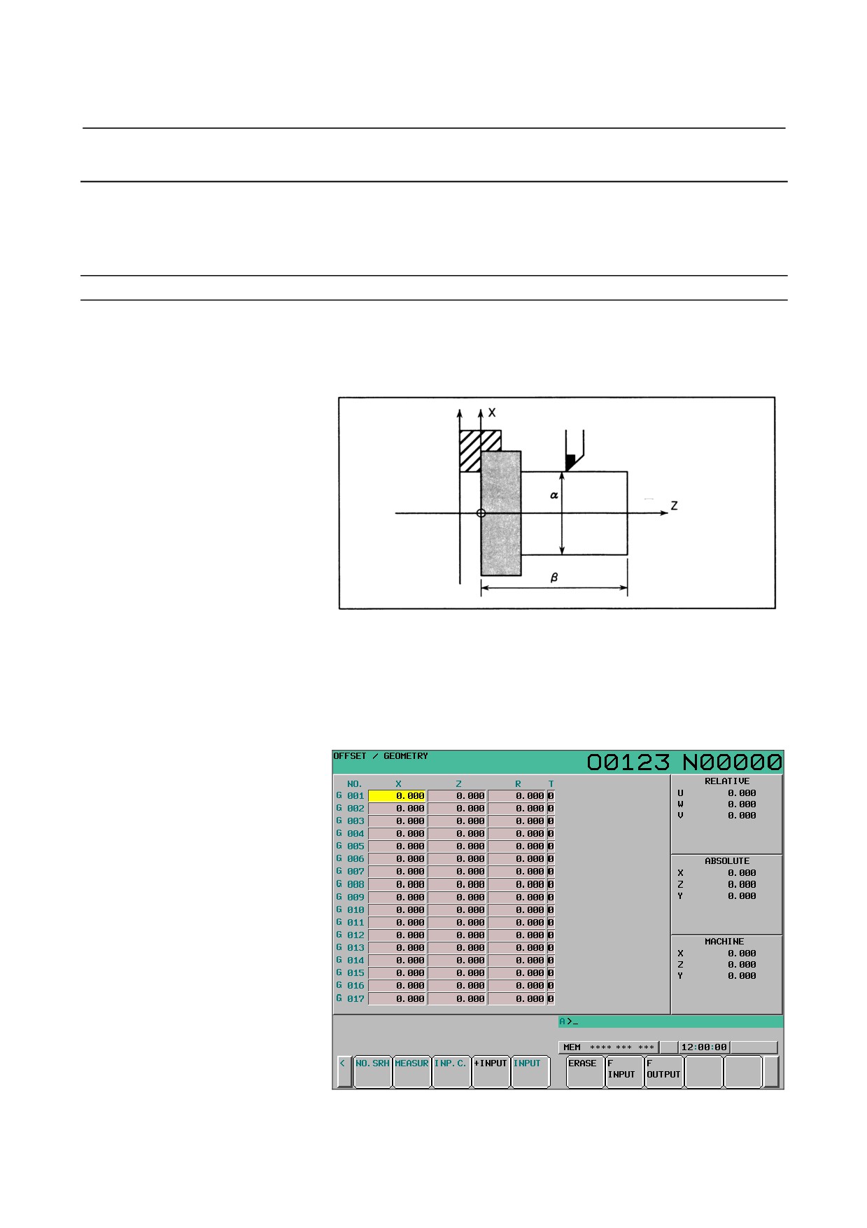
Cut surface A in manual mode with an actual tool.
Suppose that a workpiece coordinate system has been set.
Surface B
Surface A
Fig. 2.1.2 (a)
2
Release the tool in X-axis direction only, without moving Z-axis
and stop the spindle.
3
Measure distance β from the origin in the workpiece coordinate
system to surface A.
Set this value as the measured value along the Z-axis for the
desired offset number, using the following procedure:
Fig. 2.1.2 (b) Tool offset screen (10.4-inch)
- 374 -
B-64304EN-1/01
OPERATION
2.SETTING AND DISPLAYING DATA
3-1 Press the function key
or the soft key [OFFSET] to
display the tool offset screen. If geometry compensation
values and wear offset values are separately specified,
display the screen for either of them.
3-2 Move the cursor to the set offset number using cursor keys.
3-3 Press the address key
to be set.
3-4 Key in the measured value (β).
3-5 Press the soft key [MESURE].
The difference between measured value β and the
coordinate is set as the offset value.
- Setting of X axis offset value
4
Cut surface B in manual mode.
5
Release the tool in the Z-axis direction without moving the
X-axis and stop the spindle.
6
Measure the diameter α of surface B.
Set this value as the measured value along the X-axis for the
desired offset number in the same way as when setting the value
along the Z-axis.
7
Repeat above procedure the same time as the number of the
necessary tools.
The offset value is automatically calculated and set.
For example, in case α=69.0 when the coordinate value of surface B
in the diagram above is 70.0, set 69.0 [MEASURE] at offset No. 2.
In this case, 1.0 is set as the X-axis offset value to offset No. 2.
Explanation
- Offset values for a program created in diameter programming
Enter diameter values for the offset values for axes for which diameter
programming is used.
- Tool geometry offset value and tool wear offset value
If measured values are set on the tool geometry offset screen, all offset
values become geometry offset values and all wear offset values are
set to 0. If measured values are set on the tool wear offset screen, the
differences between the measured offset values and the current wear
offset values become the new offset values.
- Release of both axes
When the record button is provided on the machine side, the tool can
be released in the directions of the two axes by setting bit 2 (PRC) of
parameter No. 5005 or using the position record signal. For details on
the position record signal, refer to the manual issued by the machine
tool builder.
- 375 -
2.SETTING AND DISPLAYING DATA OPERATION
B-64304EN-1/01
2.1.3
Direct Input of Tool Offset Value Measured B
Explanation
- Basic procedure to set tool offset value
To use the tool setter function for a one-turret/two-spindle lathe, first
specify the spindle to be measured, using the S2TLS
(G040.5)
(spindle measurement select) signal.
(1)
Execute manual reference position return.
By executing manual reference position return, a machine
coordinate system is established.
The tool offset value is computed on the machine coordinate
system.
(2)
Select manual handle mode or manual continuous feed mode and
set the tool compensation value write mode select signal
GOQSM to “1”. The LCD display is automatically changed to
the tool offset screen (geometry), and the “OFST” indicator starts
blinking in the status indication area at the bottom of the screen,
which indicates that the tool compensation value writing mode is
ready. When the tool setter function for a one-turret/two-spindle
lathe is in use, the S1MES or S2MES
(spindle under
measurement) signal, whichever is applicable, becomes 1.
CAUTION
After this, it is impossible to switch the S2TLS
(spindle measurement selection) signal until the
GOQSM (offset write mode) signal becomes 0.
(3)
Select a tool to be measured.
(4)
When the cursor does not coincide with the tool offset number
desired to be set, move the cursor to the desired offset number
using the page key and cursor key.
The cursor can also be coincided with the tool offset number
desired to be set automatically by the tool offset number input
signals (when parameter QNI(No.5005#5)=1).
In this case, the position of the cursor cannot be changed on the
tool compensation screen using page keys or cursor keys.
(5)
Near the tool to the sensor by manual operation.
(6)
Place the tool edge to a contacting surface of the sensor by
manual handle feed.
Bring the tool edge in contact with the sensor. This causes the
tool compensation value writing signals to input to be CNC.
The following tool compensation amount write signals are set up
according to the setting of the bit 3 (TS1)of parameter No. 5004.
When the parameter is 0: +MIT1, -MIT1, +MIT2, -MIT2
When the parameter is 1: +MIT1 only
If the tool compensation value writing signal is set to “1”:
i)
The axis is interlocked in this direction and its feed is
stopped.
ii)
The tool offset value extracted by the tool offset memory
(tool geometry offset value) which corresponds to the offset
number shown by the cursor is set up.
- 376 -
B-64304EN-1/01
OPERATION
2.SETTING AND DISPLAYING DATA
(7) For both X-axis and Z-axis, their offset values are set by
operations (5) and (6).
(8) Repeat operations (3) to (7) for all necessary tools.
(9) Set the tool compensation value writing mode signal GOQSM to
“0”.
The writing mode is canceled and the blinking “OFST” indicator
light goes off.
When the tool setter function for a one-turret/two-spindle lathe
is in use, the S1MES or S2MES (spindle under measurement)
signal for the spindle being measured becomes 0.
- Basic procedure to set workpiece coordinate shift value
To use the tool setter function for a one-turret/two-spindle lathe, first
specify the spindle to be measured, using the S2TLS
<G040.5>
(spindle measurement select) signal.
(1)
Set the tool geometry offset values of each tool in advance.
(2)
Execute manual reference position return.
By executing manual reference position return, the machine
coordinate system is established.
The workpiece coordinate system shift amount is computed
based on the machine coordinate system of the tool.
(3)
Set the workpiece coordinate system shift amount writing mode
select signal WOQSM to “1”.
The LCD display automatically switches to the workpiece
shifting screen, the “WFST” indicator starts blinking at the status
indicator area in the bottom of the screen, which indicates that
the workpiece coordinate system shift amount writing mode is
ready.
When the tool setter function for a one-turret/two-spindle lathe
is in use, the workpiece coordinate system screen is selected, and
the S1MES or S2MES (spindle under measurement) signal,
whichever is applicable, becomes 1.
CAUTION
After this, it is impossible to switch the S2TLS
(spindle measurement selection) signal until the
WOQSM (offset write mode) signal becomes 0.
(4)
Select a tool to be measured.
(5)
Check tool offset numbers.
The tool offset number corresponding to the tool required for
measurement, shall be set in the parameter (No.5020) in advance.
The tool offset number can also be set automatically by setting
the tool offset number input signal
(with parameter
QNI(No.5005#5)=1).
(6)
Manually approach the tool to an end face of the workpiece.
(7)
Place the tool edge to the end face (sensor) of the workpiece
using manual handle feed.
When the tool edge contacts the end face of the workpiece, input
the workpiece coordinate system shift amount signal WOSET.
The workpiece coordinate system shift amount on the Z-axis is
automatically set.
- 377 -
2.SETTING AND DISPLAYING DATA OPERATION
B-64304EN-1/01
(8) Release the tool.
(9) Set the workpiece coordinate system shift amount write mode
select signal WOQSM to “0”.
The writing mode is canceled and the blinking “WSFT” indicator
light goes off.
When the tool setter function for a one-turret/two-spindle lathe
is in use, the S1MES or S2MES (spindle under measurement)
signal, whichever is applicable, becomes 0.
- 378 -
B-64304EN-1/01
OPERATION
2.SETTING AND DISPLAYING DATA
2.1.4
Counter Input of Offset value
By moving the tool until it reaches the desired reference position, the
corresponding tool offset value can be set.
Counter input of offset value
Procedure
1
Manually move the reference tool to the reference position.
2
Reset the relative coordinates along the axes to 0.
3
Move the tool for which offset values are to be set to the
reference position.
4
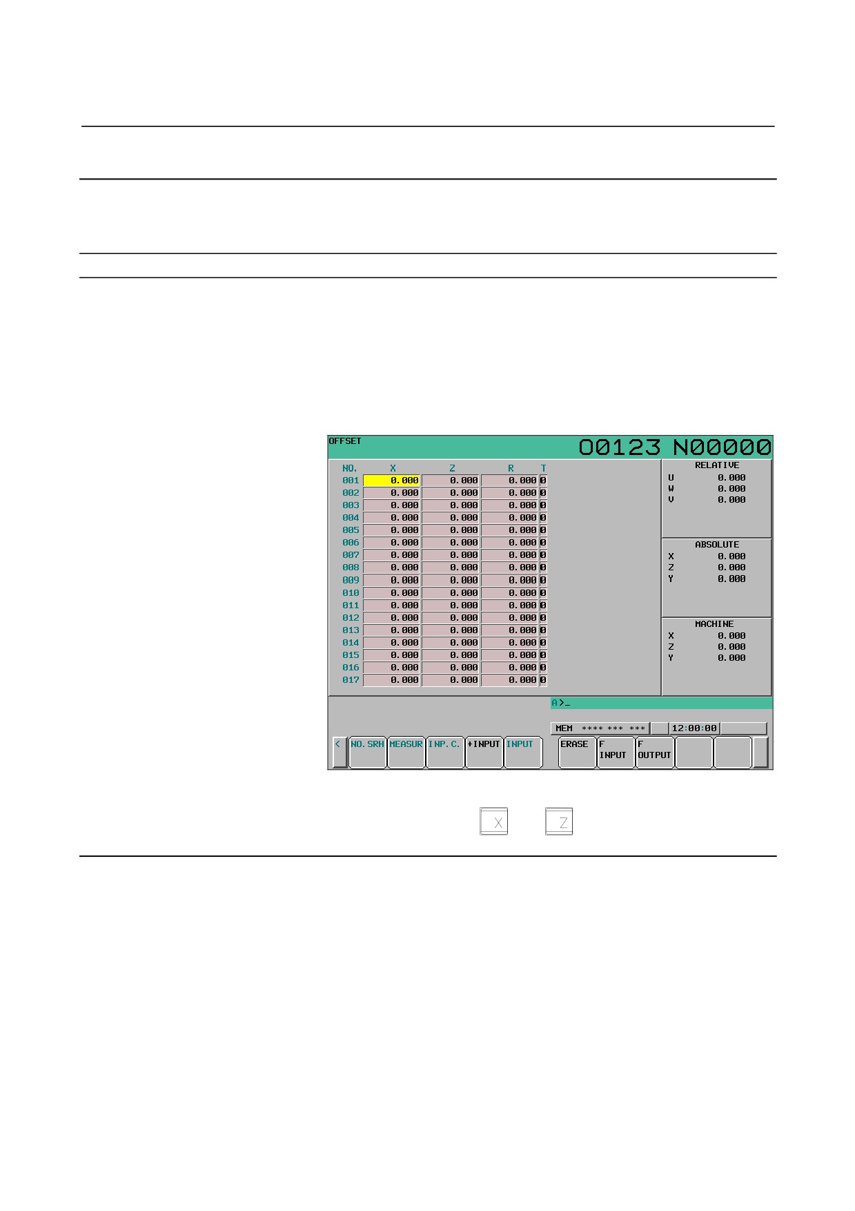
Select the tool offset screen. Move the cursor to the offset value
to be set using cursor keys.
Fig. 2.1.4 (a) Tool offset screen (10.4-inch)
5
Press address key
(or
) and the soft key [INP.C.].
Explanation
- Geometry offset and wear offset
When the above operations are performed on the tool geometry offset
screen, tool geometry offset values are input and tool wear offset
values do not change.
When the above operations are performed on the tool wear offset
screen, tool wear offset values are input and tool geometry offset
values do not change.
- 379 -
2.SETTING AND DISPLAYING DATA OPERATION
B-64304EN-1/01
2.1.5
Setting the Workpiece Coordinate System Shift Value
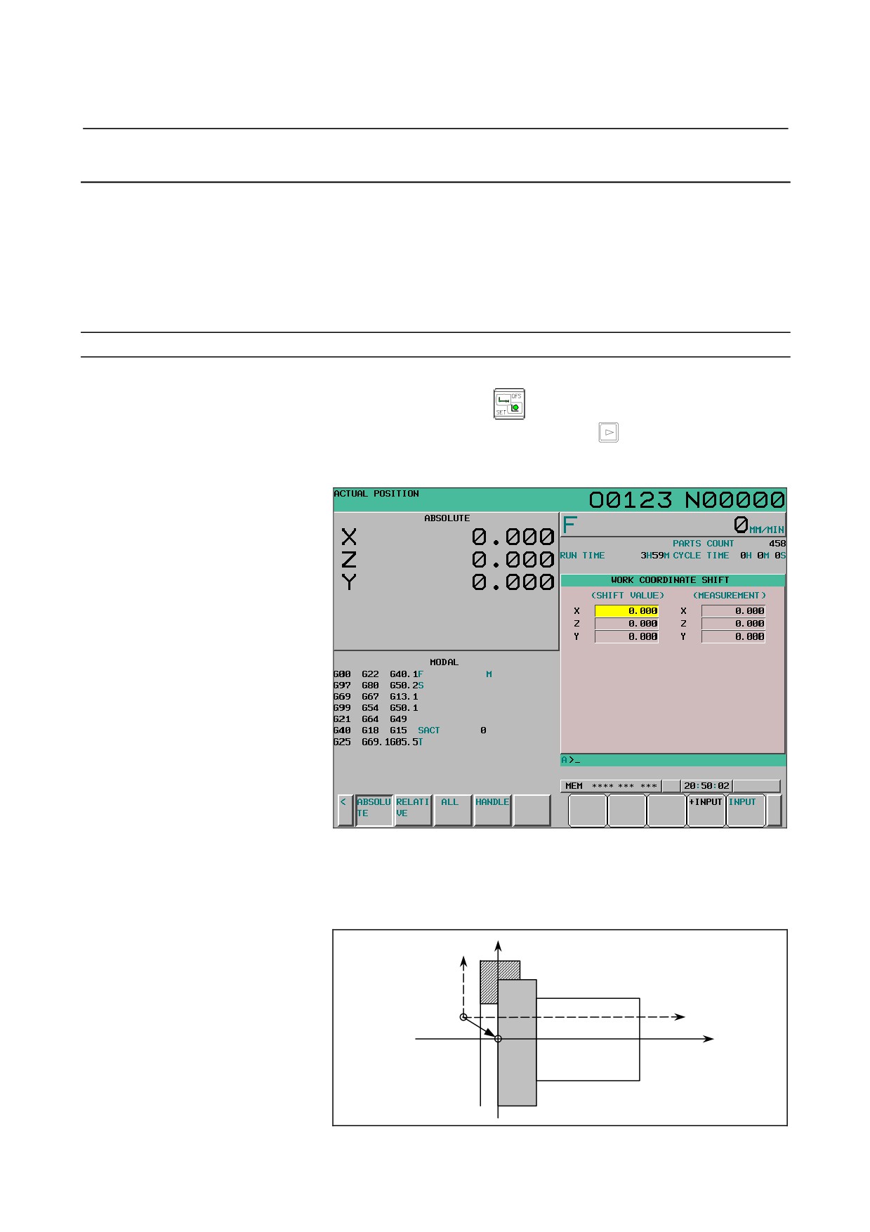
The set coordinate system can be shifted when the coordinate system
which has been set by a G50 command (or G92 command for G code
system B or C) or automatic coordinate system setting is different
from the workpiece coordinate system assumed at programming.
When a T series system is used, the workpiece coordinate system shift
screen is displayed.
Setting the workpiece coordinate system shifting amount
Procedure
1
Press function key
2
Press the continuous menu key
several times until the
screen with soft key [W.SHFT] is displayed.
3
Press soft key [W.SHFT].
Fig. 2.1.5 (a) Workpiece coordinate system shift screen (10.4-inch)
4
Move the cursor using cursor keys to the axis along which the
coordinate system is to be shifted.
5
Enter the shift value and press soft key [INPUT].
X
X’
O’
Z’
Shift
Z
O
Fig. 2.1.5 (b)
- 380 -
B-64304EN-1/01
OPERATION
2.SETTING AND DISPLAYING DATA
Explanation
- When shift values become valid
Shift values become valid immediately after they are set.
- Shift values and coordinate system setting command
Setting a command (G50 or G92) for setting a coordinate system
disables the set shift values.
Example)
When G50 X100.0 Z80.0; is specified, the coordinate system is
set so that the current tool reference position is X+100.0, Z+80.0
regardless of the shift values.
- Shift values and coordinate system setting
If the automatic coordinate system setting is performed by manual
reference position return after shift amount setting, the coordinate
system is shifted instantly.
- Diameter or radius value
Whether the shift amount on the X-axis is diameter or radius value
depends on that specified in program.
- Position record signal
When bit
2
(PRC) of parameter No.
5005 is
1, the absolute
coordinates when the position record signal is ON are recorded for
calculation of the shift amount.
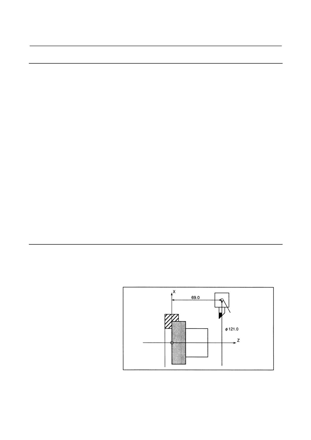
Example
When the actual position of the reference point is X=121.0 (diameter),
Z=69.0 with respect to the workpiece origin but it should be X=120.0,
Z=70.0, set the following shift values:
Shit value setting: X=1.0, Z=-1.0
Start position
(Standard position)
Fig. 2.1.5 (c)
- 381 -
2.SETTING AND DISPLAYING DATA OPERATION
B-64304EN-1/01
2.1.6
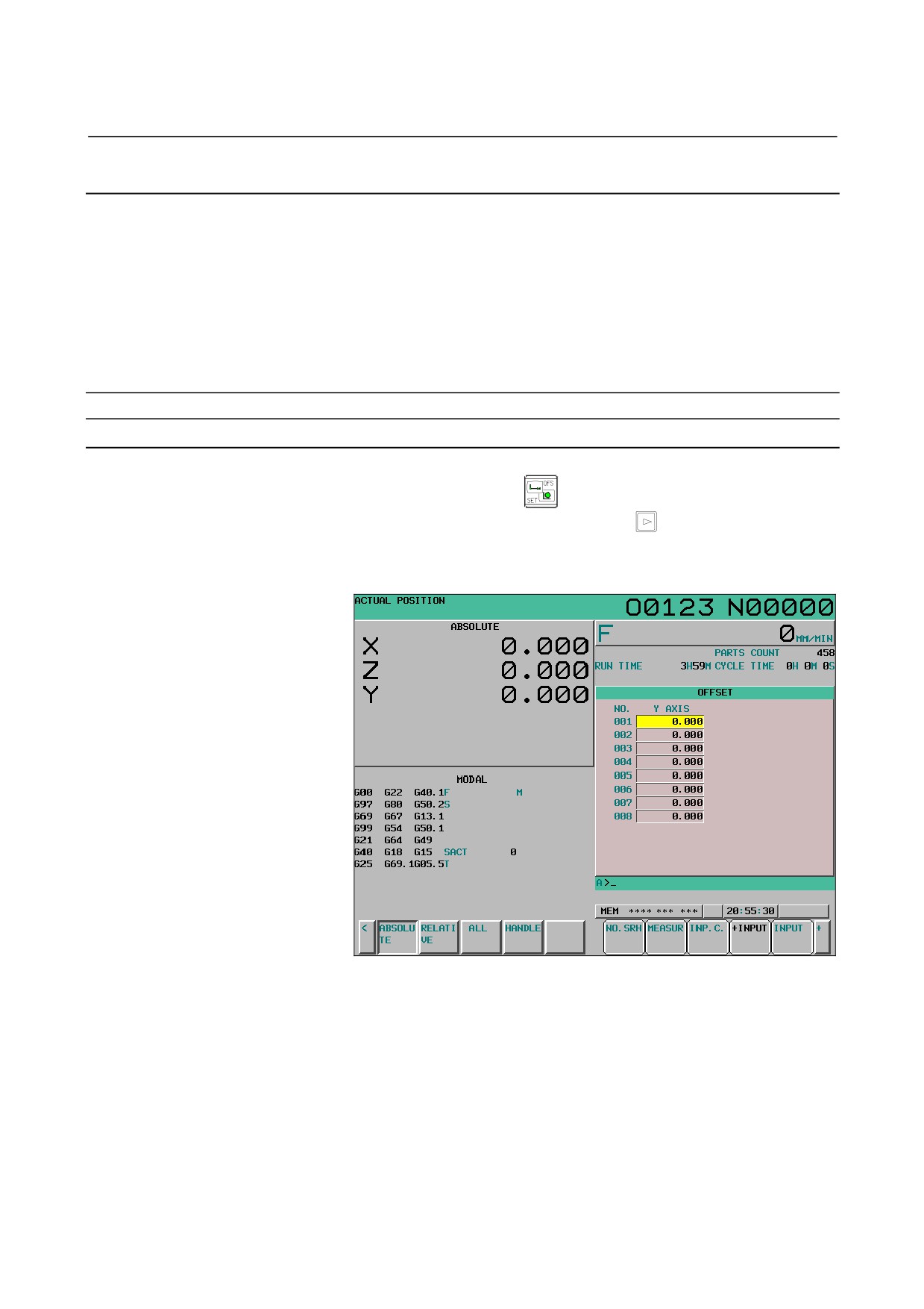
Setting the Y-Axis Offset
Tool position offset values along the Y-axis can be set. Counter input
of offset values is also possible.
For the Y-axis, no tool offset value can be directly input.
Whether the Y-axis offset is to be used can be selected using bit 1
(YOF) of parameter No.
8132.
(0: Does not use the Y-axis
offset./1: Uses the Y-axis offset.)
When the Y-axis is not used according to the setting, the screen is not
also displayed.
Procedure for setting the tool offset value of the Y axis
Procedure
1
Press function key
2
Press the continuous menu key
several times until the
screen with soft key [Y OFFSET] is displayed.
3
Press soft key
[Y OFFSET]. The Y-axis offset screen is
displayed.
Fig. 2.1.6 (a) Y-axis offset screen (10.4-inch)
- 382 -
B-64304EN-1/01
OPERATION
2.SETTING AND DISPLAYING DATA
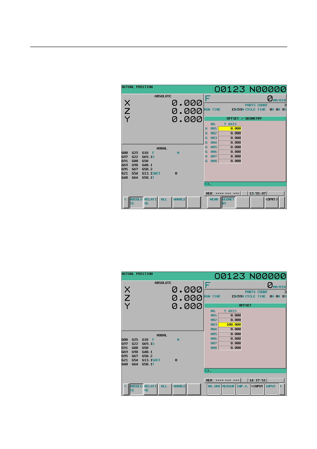
3-1 When the [GEOMETRY] soft key is pressed, Y-axis tool
geometry compensation data is displayed. Press the
[WEAR] soft key to switch the screen display to the display
of tool wear compensation data.
Fig. 2.1.6 (b) Y-axis offset screen (tool geometry) (10.4-inch)
4
Position the cursor at the offset number to be changed by using
either of the following methods:
•
Move the cursor to the offset number to be changed using
page keys and cursor keys.
•
Type the offset number and press soft key [NO.SRH].
5
Enter the offset value.
6
Press soft key [INPUT]. The offset value is set and displayed.
Fig. 2.1.6 (c) Y-axis offset screen (input) (10.4-inch)
- 383 -
2.SETTING AND DISPLAYING DATA OPERATION
B-64304EN-1/01
Procedure for counter input of the offset value
Procedure
To set relative coordinates along the Y-axis as offset values:
1
Move the reference tool to the reference point.
2
Reset relative coordinate Y to 0.
3
Move the tool for which offset values are to be set to the
reference point.
4
Move the cursor to the value for the offset number to be set,
press
key, then press soft key [INP.C.].
Relative coordinate Y (or V) is now set as the offset value.
- 384 -
B-64304EN-1/01
OPERATION
2.SETTING AND DISPLAYING DATA
2.1.7
Chuck and Tail Stock Barriers
The chuck and tail stock barrier function prevents damage to the
machine by checking whether the tool nose fouls either the chuck or
tail stock. Specify an area into which the tool may not enter
(entry-inhibition area). This is done using the special setting screen,
according to the shapes of the chuck and tail stock. If the tool nose
should enter the set area during a machining operation, this function
stops the tool and outputs an alarm message. The tool can be cleared
from the area only by retracting it in the direction opposite to that in
which the tool entered the area.
Whether the chuck and tail stock barrier function is to be used can be
selected using bit 1 (BAR) of parameter No. 8134.
(0: Does not
use the function./1: Uses the function.)
When the function is not used, the screen is not also displayed.
Setting the chuck and tail stock barriers
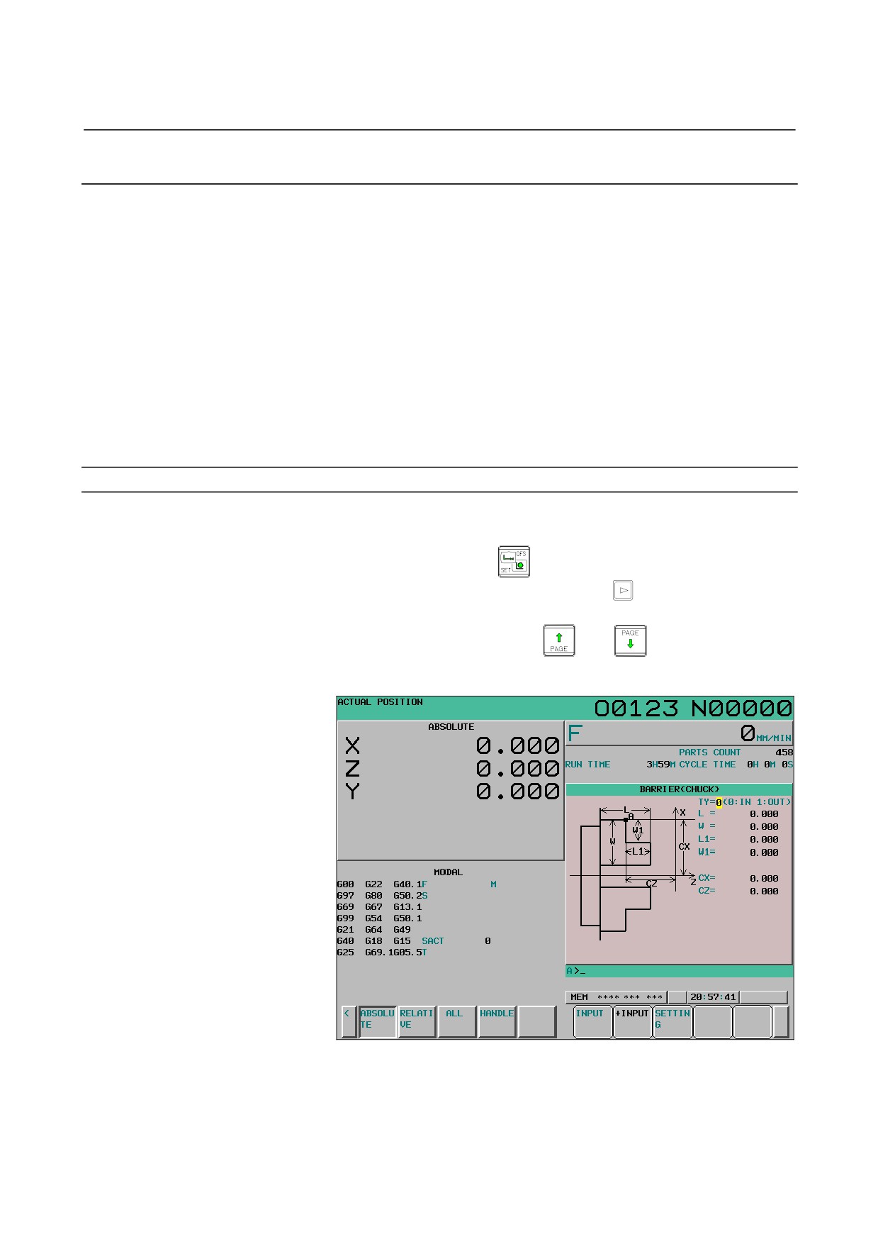
Procedure
- Setting the shapes of the chuck and tail stock
1
Press function key
2
Press the continuous menu key
. Then, press chapter
selection soft key [BARRIER].
3
Pressing the page key
or
toggles the display
between the chuck barrier setting screen and tail stock barrier
setting screen.
Fig. 2.1.7 (a) Chuck barrier setting screen (10.4-inch)
- 385 -
2.SETTING AND DISPLAYING DATA OPERATION
B-64304EN-1/01
Fig. 2.1.7 (b) Tail stock barrier setting screen (10.4-inch)
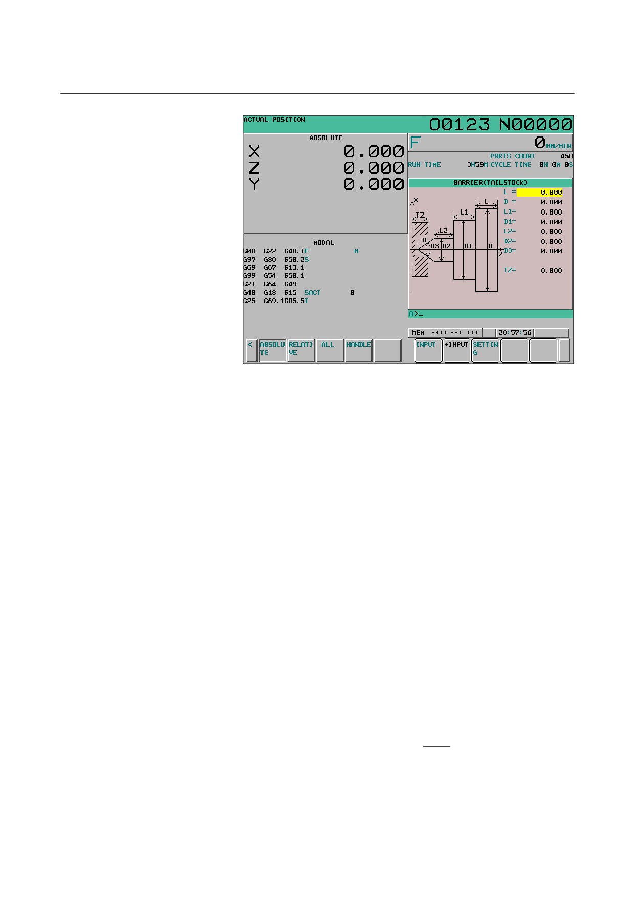
4
Position the cursor to each item defining the shape of the chuck
or tail stock, enter the corresponding value, then press soft key
[INPUT]. The value is set. Pressing soft key [+INPUT] after a
value has been entered adds the entered value to the current value,
the new setting being the sum of the two values.
Items CX and CZ, both on the chuck barrier setting screen, and
item TZ on the tail stock barrier setting screen can also be set in
another way. Manually move the tool to the desired position,
then press soft key [SETTING] to set the coordinate(s) of the
tool in the workpiece coordinate system. If a tool having an
offset other than 0 is manually moved to the desired position
with no compensation applied, compensate for the tool offset in
the set coordinate system. Items other than CX, CZ, and TZ
cannot be set by using soft key [SETTING].
Example
When an alarm is issued, the tool stops before the
entry-inhibition area if bit 7 (BFA) of parameter No. 1300 is
set to 1. If bit 7 (BFA) of parameter No. 1300 is set to 0, the
tool stops at a more inside position than the specified figure
because the CNC and machine system stop with some delay
in time.
For safety, therefore, set an area a little larger than the
determined area. The distance between the boundaries of
these two areas, L, is calculated from the following equation,
based on the rapid traverse rate.
1
L = (Rapid traverse rate) ×
7500
When the rapid traverse rate is 15 m/min, for example, set
an area having a boundary
2 mm outside that of the
determined area.
The shapes of the chuck and tail stock can be set using
parameters Nos. 1330 to 1348
- 386 -
B-64304EN-1/01
OPERATION
2.SETTING AND DISPLAYING DATA
NOTE
Set G23 mode before attempting to specify the
shapes of the chuck and tail stock.
- Reference position return
Return the tool to the reference position along the X- and Z-axes.
The chuck-tail stock barrier function becomes effective only once
reference position return has been completed after power on.
When an absolute position detector is provided, reference position
return need not always be performed. The positional relationship
between the machine and the absolute position detector, however,
must be determined.
- G22/G23
When G22 (stored stroke limit on) is specified, the chuck and tail
stock area becomes an entry-inhibition area. When G23 (stored stroke
limit off) is specified, the entry-inhibition area is canceled.
Even if G22 is specified, the entry-inhibition area for the tail stock can
be disabled by issuing a tail stock barrier signal. When the tail stock is
pushed up against a workpiece or separated from the workpiece by
using the auxiliary functions, PMC signals are used to enable or
disable the tail stock setting area.
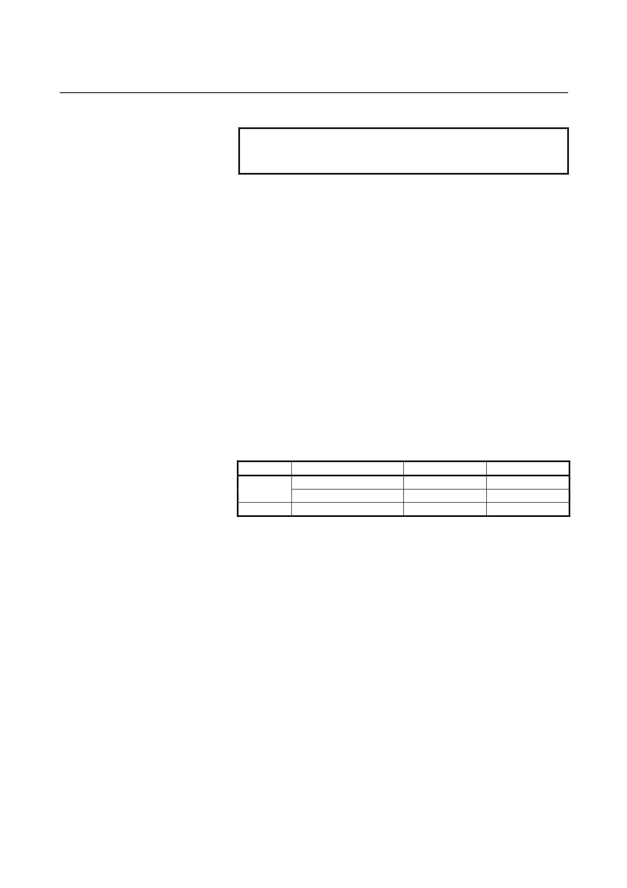
Table 2.1.7 (a)
G code
Tail stock barrier signal
Chuck barrier
Tail stock barrier
0
Valid
Valid
G22
1
Valid
Invalid
G23
Unrelated
Invalid
Invalid
G22 is selected when the power is turned on. Using G23, bit 7 of
parameter No. 3402, however, it can be changed to G23.
- 387 -
2.SETTING AND DISPLAYING DATA OPERATION
B-64304EN-1/01
Explanation
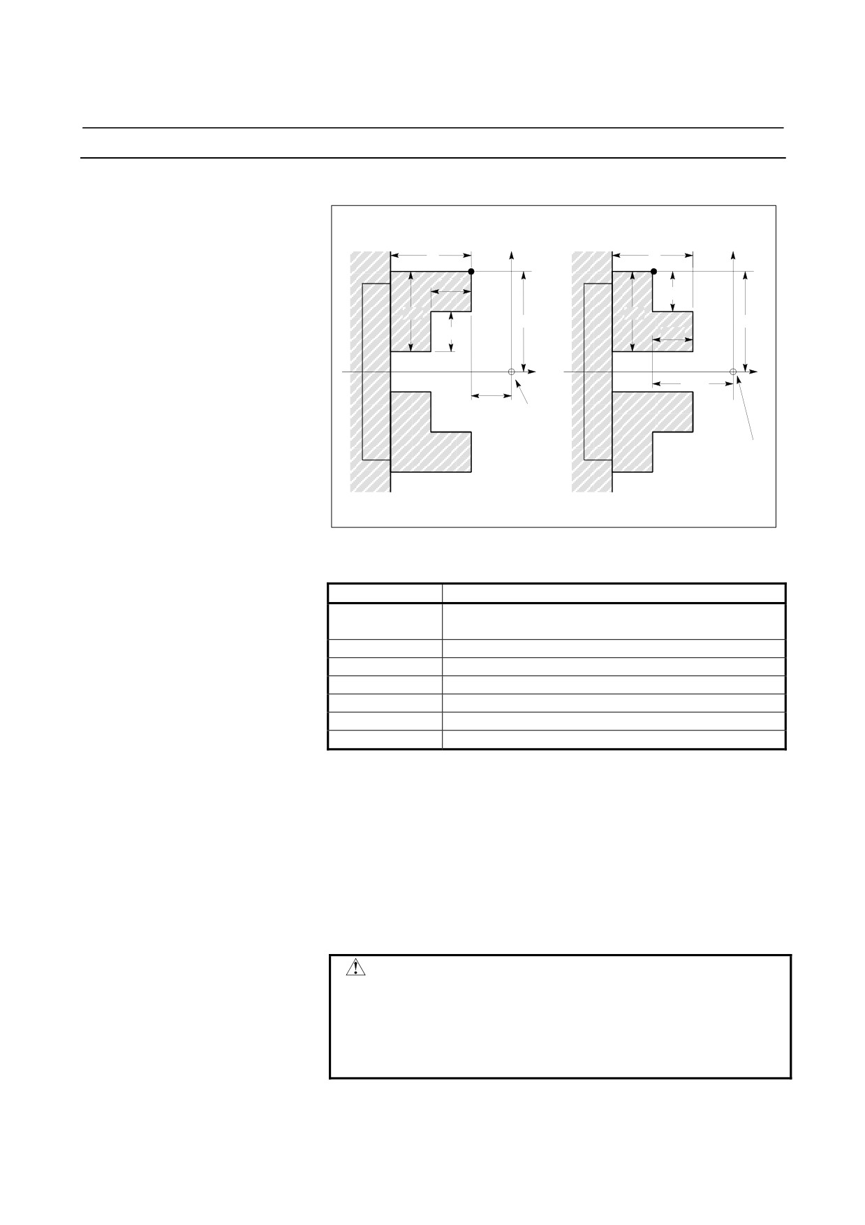
- Setting the shape of the chuck barrier
•
Chuck holding the outer
• Chuck holding the
face of a tool
inner face of a tool
X
X
L
L
A
A
L1
W1
W
W
CX
CX
W1
L1
Z
Z
CZ
CZ
Origin of
workpiece
coordinate system
Origin of
workpiece
coordinate system
Note) The hatched areas indicate entry-inhibition areas.
Fig. 2.1.7 (c)
Table2.1.7 (b)
Symbol
Description
TY
Chuck-shape selection (0: Holding the inner face of a tool,
1: Holding the outer face of a tool)
CX
Chuck position (along X-axis)
CZ
Chuck position (along Z-axis)
L
Length of chuck jaws
W
Depth of chuck jaws (radius)
L1
Holding length of chuck jaws
W1
Holding depth of chuck jaws (radius)
TY : Selects a chuck type, based on its shape. Specifying 0 selects a
chuck that holds the inner face of a tool. Specifying 1 selects a
chuck that holds the outer face of a tool. A chuck is assumed to
be symmetrical about its Z-axis.
CX, CZ :
Specify the coordinates of a chuck position, point A, in the
workpiece coordinate system. These coordinates are not the same
as those in the machine coordinate system. The unit of data is
indicated in Table 2.1.7(c).
CAUTION
Whether diameter programming or radius
programming is used for the axis determines the
programming system. When diameter programming
is used for the axis, use diameter programming to
enter data for the axis.
- 388 -
B-64304EN-1/01
OPERATION
2.SETTING AND DISPLAYING DATA
Table 2.1.7 (c)
Increment
Unit of data
Valid data range
system
IS-A
IS-B
Metric input
0.001 mm
0.0001 mm
-99999999 to +99999999
Inch input
0.0001 inch
0.00001 inch
-99999999 to +99999999
L, L1, W, W1 : Define the figure of a chuck. The unit of data is
indicated in Table 2.1.7(c).
CAUTION
Always specify W and W1 in radius. When radius
programming is used for the Z-axis, specify L and
L1 in radius.
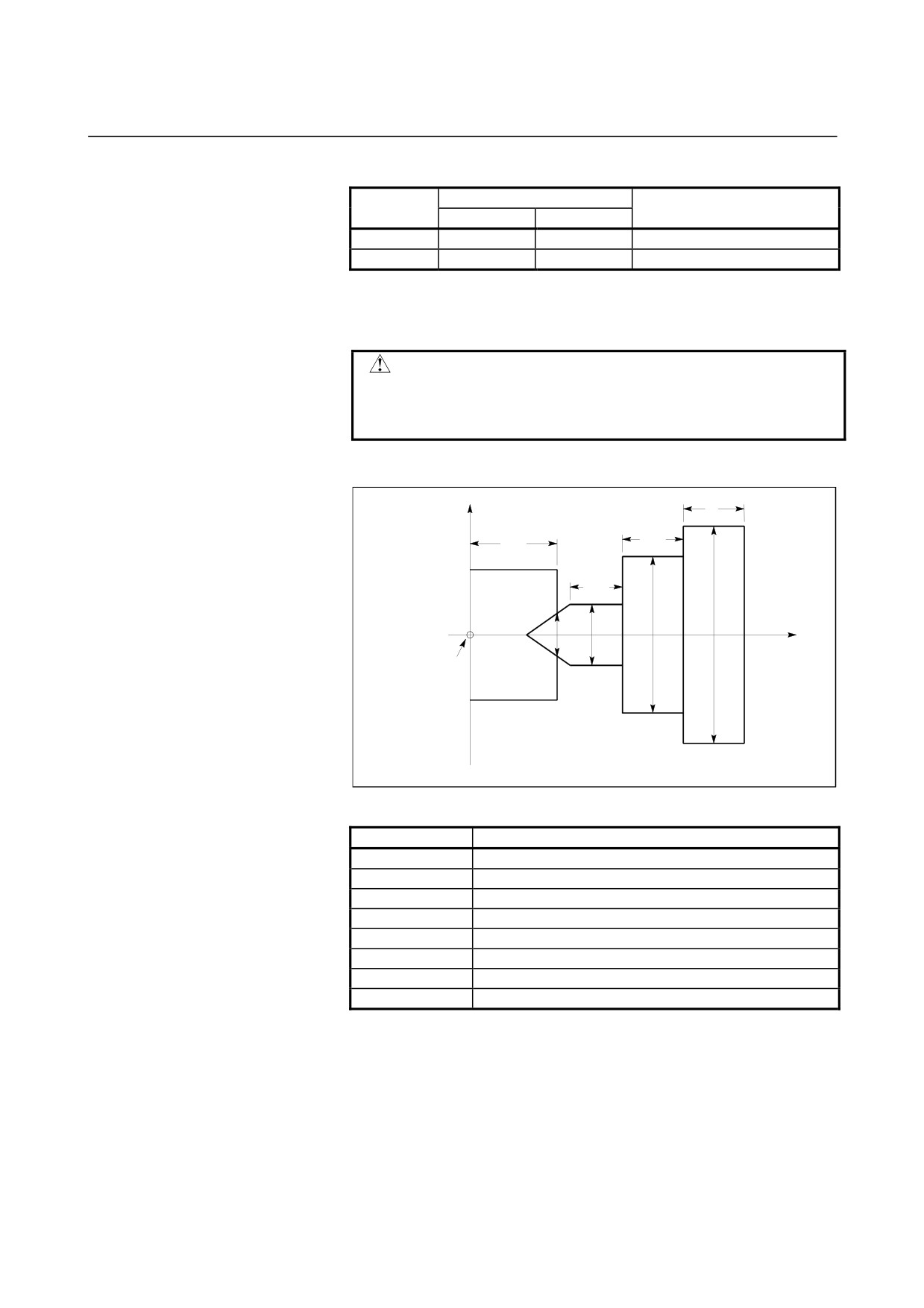
- Setting the shape of a tail stock barrier
L
TZ
L1
L2
B
Workpiece
Z
D3
D2
D1
D
Workpiece
coordinate system
origin
Table 2.1.7 (d)
Symbol
Description
TZ
Tail stock position (along the Z-axis)
L
Tail stock length
D
Tail stock diameter
L1
Tail stock length (1)
D1
Tail stock diameter (1)
L2
Tail stock length (2)
D2
Tail stock diameter (2)
D3
Tail stock hole diameter (3)
TZ : Specifies the Z coordinate of the chuck position, point B, in the
workpiece coordinate system. These coordinates are not the same
as those in the machine coordinate system. The unit of data is
indicated in Table
2.1.7(c). A tail stock is assumed to be
symmetrical about its Z-axis.
- 389 -
2.SETTING AND DISPLAYING DATA OPERATION
B-64304EN-1/01
CAUTION
Whether diameter programming or radius
programming is used for the Z-axis determines the
programming system.
L, L1, L2, D, D1, D2, D3 :
Define the figure of a tail stock. The valid data range is indicated
in Table 2.1.7(c).
CAUTION
Always specify D, D1, D2, and D3 in diameter
programming. When radius programming is used for
the Z-axis, specify L, L1, and L2 in radius.
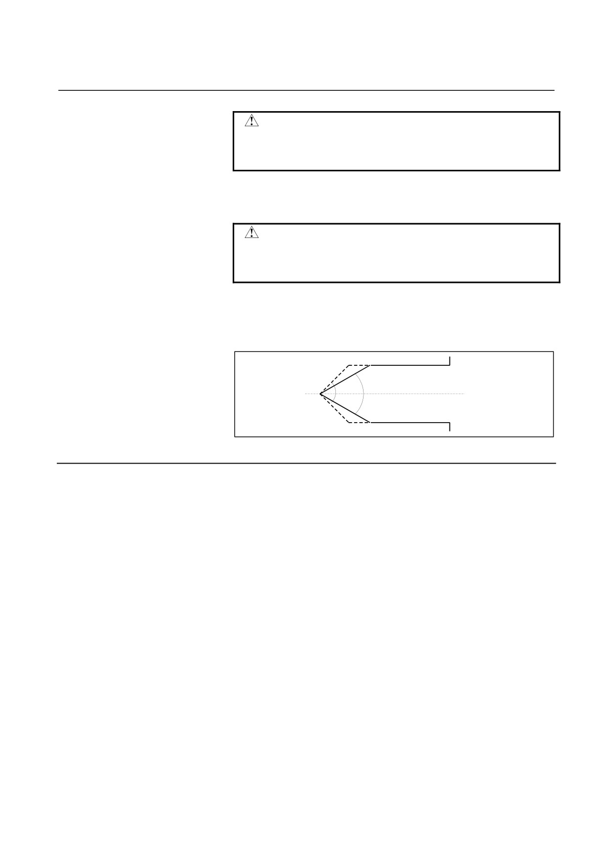
- Setting the entry-inhibition area for the tail stock tip
The tip angle of the tail stock is 60 degrees. The entry-inhibition area
is set around the tip, assuming the angle to be 90 degrees, as shown
below.
60°
90°
Fig. 2.1.7 (d)
Limitation
- Correct setting of an entry-inhibition area
If an entry-inhibition area is incorrectly set, it may not be possible to
make the area effective. Avoid making the following settings:
• L ≤ L1 or W ≤ W1 in the chuck-shape settings.
• D2 ≤ D3 in the tail stock-shape settings.
• A chuck setting overlapping that of the tail stock.
- Retraction from the entry-inhibition area
If the tool enters the entry-inhibition area and an alarm is issued,
switch to manual mode, retract the tool manually, then reset the
system to release the alarm. In manual mode, the tool can be moved
only in the opposite direction to that in which the tool entered the
area.
The tool cannot be moved in the same direction (further into the area)
as it was traveling when the tool entered the area.
When the entry-inhibition areas for the chuck and tail stock are
enabled, and the tool is already positioned within those areas, an alarm
is issued when the tool moves.
When the tool cannot be retracted, change the setting of the
entry-inhibition areas, such that the tool is outside the areas, reset the
system to release the alarm, then retract the tool. Finally, reinstall the
original settings.
- 390 -
B-64304EN-1/01
OPERATION
2.SETTING AND DISPLAYING DATA
- Coordinate system
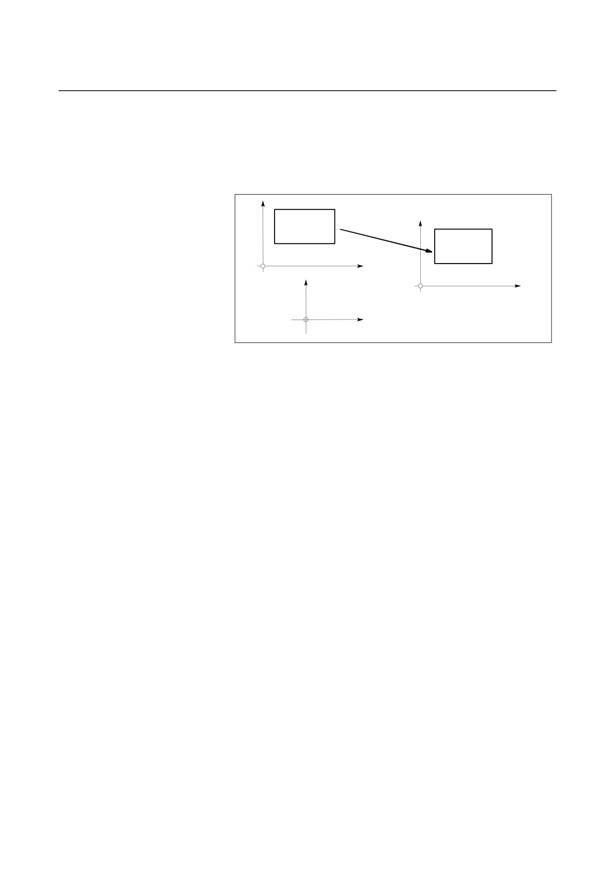
An entry-inhibition area is defined using the workpiece coordinate
system. Note the following.
<1> When the workpiece coordinate system is shifted by means of a
command or operation, the entry-inhibition area is also shifted by
the same amount.
Entry-inhibition
area
Entry-
Old workpiece
inhibition area
coordinate system
New workpiece
coordinate system
Machine coordinate system
Fig. 2.1.7 (e)
Use of the following commands and operations will shift the
workpiece coordinate system.
Commands:
G54 to G59, G52, G50 (G92 in G code system B or C)
Operations:
Manual handle interruption, change in offset relative to the
workpiece origin, change in tool offset
(tool geometry
offset), operation with machine lock, manual operation with
machine absolute signal off
<2> When the tool enters an entry-inhibition area during automatic
operation, set the manual absolute signal, *ABSM, to 0 (on), then
manually retract the tool from the area. If this signal is 1, the
distance the tool moves in manual operation is not counted in the
tool coordinates in the workpiece coordinate system. This results
in the state where the tool can never be retracted from the
entry-inhibition area.
- Stored stroke check 2/3
When both stored stroke check 2/3 and the chuck tail stock barrier
function are provided, the barrier takes priority over the stored stroke
check. Stored stroke check 2/3 is ignored.
- 391 -
APPENDIX
B-64304EN-1/01
APPENDIX
A.PARAMETERS
A
PARAMETERS
This manual describes all parameters indicated in this manual.
For those parameters that are not indicated in this manual and other
parameters, refer to the parameter manual.
Appendix A, "PARAMETERS", consists of the following sections:
A.1 DESCRIPTION OF PARAMETERS
396
A.2 DATA TYPE
447
A.3 STANDARD PARAMETER SETTING TABLES
448
- 395 -
A.PARAMETERS
APPENDIX
B-64304EN-1/01
A.1
DESCRIPTION OF PARAMETERS
#7
#6
#5
#4
#3
#2
#1
#0
0001
FCV
[Input type]
Setting input
[Data type]
Bit path
# 1
FCV
Program format
0: Series 0 standard format
(This format is compliant with the Series 0i-C.)
1: Series 10/11 format
NOTE
1 Programs created in the Series 10/11 program
format can be used for operation on the following
functions:
1 Subprogram call M98,M198
2 Thread cutting with equal leads G32 (T series)
3 Canned cycle G90, G92, G94 (T series)
4 Multiple repetitive canned cycle G71 to G76 (T
series)
5 Drilling canned cycle
G80 to G89 (T series)
2 When the program format used in the Series 10/11
is used for this CNC, some limits may add. Refer to
the User’s Manual.
#7
#6
#5
#4
#3
#2
#1
#0
1013
IESPx
ISCx
ISAx
[Input type]
Parameter input
[Data type]
Bit axis
NOTE
When at least one of these parameters is set, the
power must be turned off before operation is
continued.
# 0
ISA
# 1
ISC
Increment system of each axis
Increment system
#1 ISCx
#0 ISAx
IS-A
0
1
IS-B
0
0
IS-C
1
0
- 396 -
B-64304EN-1/01
APPENDIX
A.PARAMETERS
# 7
IESP
When the least input increment is C (IS-C), the function to allow to set
the larger value to the parameter of the speed and the acceleration:
0: Not used.
1: Used.
As for the axis which set this parameter when the least input
increment is C (IS-C), the larger value can be set to the parameter of
the speed and the acceleration.
The valid data ranges of these parameters are indicated in the table of
velocity and angular velocity parameters in
(C) of the standard
parameter setting tables and the table of acceleration and angular
acceleration parameters in (D).
When this function is made effective, the digit number below the
decimal point of the parameter on input screen is changed. The digit
number below the decimal point decreases by one digit in case of the
least input increment C (IS-C).
1022
Setting of each axis in the basic coordinate system
[Input type]
Parameter input
[Data type]
Byte axis
[Valid data range]
0 to 7
To determine a plane for circular interpolation, tool radius/tool nose
radius compensation, and so forth (G17: Xp-Yp plane, G18: Zp-Xp
plane, G19: Yp-Zp plane), specify which of the basic three axes (X, Y,
and Z) is used for each control axis, or a parallel axis of which basic
axis is used for each control axis.
A basic axis (X, Y, or Z) can be specified only for one control axis.
Two or more control axes can be set as parallel axes for the same basic
axis.
Setting
Meaning
0
Rotation axis (Neither the basic three axes nor a parallel axis )
1
X axis of the basic three axes
2
Y axis of the basic three axes
3
Z axis of the basic three axes
5
Axis parallel to the X axis
6
Axis parallel to the Y axis
7
Axis parallel to the Z axis
In general, the increment system and diameter/radius specification of
an axis set as a parallel axis are to be set in the same way as for the
basic three axes.
- 397 -
A.PARAMETERS
APPENDIX
B-64304EN-1/01
1031
Reference axis
[Input type]
Parameter input
[Data type]
Byte path
[Valid data range]
1 to Number of controlled axes
The unit of some parameters common to all axes such as those for dry
run feedrate and one-digit F code feed may vary according to the
increment system. An increment system can be selected by a
parameter on an axis-by-axis basis. So, the unit of those parameters is
to match the increment system of a reference axis. Set which axis to
use as a reference axis.
Among the basic three axes, the axis with the finest increment system
is generally selected as a reference axis.
1290
Distance between two opposite tool posts in mirror image
[Input type]
Parameter input
[Data type]
Real path
[Unit of data]
mm, inch (input unit)
[Minimum unit of data]
Depend on the increment system of the reference axis
[Valid data range]
0 or positive 9 digit of minimum unit of data (refer to the standard
parameter setting table (B))
(When the increment system is IS-B, 0.0 to +999999.999)
Set the distance between two opposite tool posts in mirror image.
#7
#6
#5
#4
#3
#2
#1
#0
1300
BFA
[Input type]
Setting input
[Data type]
Bit path
# 7
BFA
When the stored stroke check 1, 2, or 3 alarm is issued, an interference
alarm is issued with the inter-path interference check function (T
series), or a chuck/tail stock barrier (T series) alarm is issued:
0: The tool stops after entering the prohibited area.
1: The tool stops before the prohibited area.
1330
Profile of a chuck
[Input type]
Parameter input
[Data type]
Byte path
[Valid data range]
0 to 1
Select a chuck figure.
0 : Chuck which holds a workpiece on the inner surface
1 : Chuck which holds a workpiece on the outer surface
- 398 -
B-64304EN-1/01
APPENDIX
A.PARAMETERS
1331
Dimensions of the claw of a chuck (L)
[Input type]
Parameter input
[Data type]
Real path
[Unit of data]
mm, inch (input unit)
[Minimum unit of data]
Depend on the increment system of the applied axis
[Valid data range]
0 or positive 9 digit of minimum unit of data (refer to the standard
parameter setting table (B))
(When the increment system is IS-B, 0.0 to +999999.999)
Set the length (L) of the claw of the chuck.
NOTE
Whether to specify this parameter by using a
diameter value or radius value depends on whether
the corresponding axis is based on diameter
specification or radius specification.
1332
Dimensions of the claw of a chuck (W)
[Input type]
Parameter input
[Data type]
Real path
[Unit of data]
mm, inch (input unit)
[Minimum unit of data]
Depend on the increment system of the applied axis
[Valid data range]
0 or positive 9 digit of minimum unit of data (refer to the standard
parameter setting table (B))
(When the increment system is IS-B, 0.0 to +999999.999)
Set the width (W) of the claw of the chuck.
NOTE
Specify this parameter by using a radius value at
all times.
1333
Dimensions of the claw of a chuck (L1)
[Input type]
Parameter input
[Data type]
Real path
[Unit of data]
mm, inch (input unit)
[Minimum unit of data]
Depend on the increment system of the applied axis
[Valid data range]
0 or positive 9 digit of minimum unit of data (refer to the standard
parameter setting table (B))
(When the increment system is IS-B, 0.0 to +999999.999)
Set the length (L1) of the claw of the chuck.
NOTE
Whether to specify this parameter by using a
diameter value or radius value depends on whether
the corresponding axis is based on diameter
specification or radius specification.
- 399 -
A.PARAMETERS
APPENDIX
B-64304EN-1/01
1334
Dimensions of the claw of a chuck (W1)
[Input type]
Parameter input
[Data type]
Real path
[Unit of data]
mm, inch (input unit)
[Minimum unit of data]
Depend on the increment system of the applied axis
[Valid data range]
0 or positive 9 digit of minimum unit of data (refer to the standard
parameter setting table (B))
(When the increment system is IS-B, 0.0 to +999999.999)
Set the width (W1) of the claw of the chuck.
NOTE
Specify this parameter by using a radius value at
all times.
1335
X coordinate of a chuck (CX)
[Input type]
Parameter input
[Data type]
Real path
[Unit of data]
mm, inch (input unit)
[Minimum unit of data]
Depend on the increment system of the applied axis
[Valid data range]
9 digit of minimum unit of data (refer to standard parameter setting
table (A))
(When the increment system is IS-B, -999999.999 to +999999.999)
Set the chuck position (X coordinate) in the workpiece coordinate
system.
NOTE
Whether to specify this parameter by using a
diameter value or radius value depends on whether
the corresponding axis is based on diameter
specification or radius specification.
- 400 -
B-64304EN-1/01
APPENDIX
A.PARAMETERS
1336
Z coordinate of a chuck (CZ)
[Input type]
Parameter input
[Data type]
Real path
[Unit of data]
mm, inch (input unit)
[Minimum unit of data]
Depend on the increment system of the applied axis
[Valid data range]
9 digit of minimum unit of data (refer to standard parameter setting
table (A))
(When the increment system is IS-B, -999999.999 to +999999.999)
Set the chuck position (Z coordinate) in the workpiece coordinate
system.
NOTE
Whether to specify this parameter by using a
diameter value or radius value depends on whether
the corresponding axis is based on diameter
specification or radius specification.
1341
Length of a tail stock (L)
[Input type]
Parameter input
[Data type]
Real path
[Unit of data]
mm, inch (input unit)
[Minimum unit of data]
Depend on the increment system of the applied axis
[Valid data range]
0 or positive 9 digit of minimum unit of data (refer to the standard
parameter setting table (B))
(When the increment system is IS-B, 0.0 to +999999.999)
Set the length (L) of the tail stock.
NOTE
Whether to specify this parameter by using a
diameter value or radius value depends on whether
the corresponding axis is based on diameter
specification or radius specification.
1342
Diameter of a tail stock (D)
[Input type]
Parameter input
[Data type]
Real path
[Unit of data]
mm, inch (input unit)
[Minimum unit of data]
Depend on the increment system of the applied axis
[Valid data range]
0 or positive 9 digit of minimum unit of data (refer to the standard
parameter setting table (B))
(When the increment system is IS-B, 0.0 to +999999.999)
Set the diameter (D) of the tail stock.
NOTE
Specify this parameter by using a diameter value at
all times.
- 401 -
A.PARAMETERS
APPENDIX
B-64304EN-1/01
1343
Length of a tail stock (L1)
[Input type]
Parameter input
[Data type]
Real path
[Unit of data]
mm, inch (input unit)
[Minimum unit of data]
Depend on the increment system of the applied axis
[Valid data range]
0 or positive 9 digit of minimum unit of data (refer to the standard
parameter setting table (B))
(When the increment system is IS-B, 0.0 to +999999.999)
Set the length (L1) of the tail stock.
NOTE
Whether to specify this parameter by using a
diameter value or radius value depends on whether
the corresponding axis is based on diameter
specification or radius specification.
1344
Diameter of a tail stock (D1)
[Input type]
Parameter input
[Data type]
Real path
[Unit of data]
mm, inch (input unit)
[Minimum unit of data]
Depend on the increment system of the applied axis
[Valid data range]
0 or positive 9 digit of minimum unit of data (refer to the standard
parameter setting table (B))
(When the increment system is IS-B, 0.0 to +999999.999)
Set the diameter (D1) of the tail stock.
NOTE
Specify this parameter by using a diameter value at
all times.
1345
Length of a tail stock (L2)
[Input type]
Parameter input
[Data type]
Real path
[Unit of data]
mm, inch (input unit)
[Minimum unit of data]
Depend on the increment system of the applied axis
[Valid data range]
0 or positive 9 digit of minimum unit of data (refer to the standard
parameter setting table (B))
(When the increment system is IS-B, 0.0 to +999999.999)
Set the length (L2) of the tail stock.
NOTE
Whether to specify this parameter by using a
diameter value or radius value depends on whether
the corresponding axis is based on diameter
specification or radius specification.
- 402 -
B-64304EN-1/01
APPENDIX
A.PARAMETERS
1346
Diameter of a tail stock (D2)
[Input type]
Parameter input
[Data type]
Real path
[Unit of data]
mm, inch (input unit)
[Minimum unit of data]
Depend on the increment system of the applied axis
[Valid data range]
0 or positive 9 digit of minimum unit of data (refer to the standard
parameter setting table (B))
(When the increment system is IS-B, 0.0 to +999999.999)
Set the diameter (D2) of the tail stock.
NOTE
Specify this parameter by using a diameter value at
all times.
1347
Diameter of the hole of a tail stock (D3)
[Input type]
Parameter input
[Data type]
Real path
[Unit of data]
mm, inch (input unit)
[Minimum unit of data]
Depend on the increment system of the applied axis
[Valid data range]
0 or positive 9 digit of minimum unit of data (refer to the standard
parameter setting table (B))
(When the increment system is IS-B, 0.0 to +999999.999)
Set the diameter (D3) of the tail stock.
NOTE
Specify this parameter by using a diameter value at
all times.
1348
Z coordinate of a tail stock (TZ)
[Input type]
Parameter input
[Data type]
Real path
[Unit of data]
mm, inch (input unit)
[Minimum unit of data]
Depend on the increment system of the applied axis
[Valid data range]
9 digit of minimum unit of data (refer to standard parameter setting
table (A))
(When the increment system is IS-B, -999999.999 to +999999.999)
Set the tail stock position (Z coordinate) in the workpiece coordinate
system.
NOTE
Whether to specify this parameter by using a
diameter value or radius value depends on whether
the corresponding axis is based on diameter
specification or radius specification.
- 403 -