FANUC Series 0i-MODEL D, Series 0i Mate-MODEL D. For Lathe System USER’S MANUAL - page 13
7.AXIS CONTROL FUNCTIONS
PROGRAMMING
B-64304EN-1/01
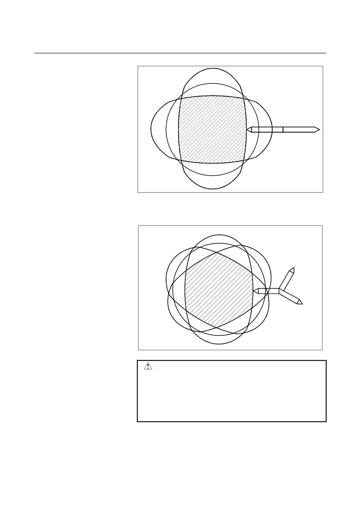
If three tools are set at every 120°, the machining figure will be a
hexagon as shown below.
WARNING
For the maximum rotation speed of the tool, see
the instruction manual supplied with the machine.
Do not specify a spindle speed higher than the
maximum tool speed or a ratio to the spindle speed
that results in a speed higher than the maximum
tool speed.
- 344 -

B-64304EN-1/01
PROGRAMMING
7.AXIS CONTROL FUNCTIONS
7.2
SYNCHRONOUS, COMPOSITE AND SUPERIMPOSED
CONTROL BY PROGRAM COMMAND (G50.4, G51.4,
G50.5, G51.5, G50.6, AND G51.6)
Synchronous control, composite control, and superimposed control
can be started or canceled using a program command instead of a DI
signal. Synchronous control, composite control, and superimposed
control based on a DI signal is also possible.
For the basic operations of synchronous control, composite control,
and superimposed control, see Sections, "SYNCHRONOUS
CONTROL AND COMPOSITE CONTROL" and Section,
"SUPERIMPOSED CONTROL" in the CONNECTION MANUAL
(FUNCTION) (B-64303EN-1).
Format
G51.4 P_ Q_ (L_) ;
Synchronous control start (L is omissible.)
G50.4 Q_ ;
Synchronous control cancel
P: Synchronous master axis ID number
Q: Synchronous slave axis ID number
L: Parking command
1: Master parking (slave parking cancel)
2: Slave parking (master parking cancel)
0: No parking (parking cancel)
(When L is omitted, the specification of L0 is assumed.)
G51.5 P_ Q_ ;
Composite control start
G50.5 P_ Q_ ;
Composite control cancel
P: Composite axis 1 ID number
Q: Composite axis 2 ID number
G51.6 P_ Q_ ;
Superimposed control start
G50.6 Q_ ;
Superimposed control cancel
P: Superimposed master axis ID number
Q: Superimposed slave axis ID number
As an ID number, set a unique value for identifying each axis in parameter
No. 12600 for both of P and Q.
G51.4/G50.4, G51.5/G50.5, and G51.6/G50.6 are one-shot G codes of
group 00.
- 345 -
7.AXIS CONTROL FUNCTIONS
PROGRAMMING
B-64304EN-1/01
Explanation
Synchronous control
Synchronous control is performed with the G51.4/G50.4 commands,
instead of simultaneously controlled axis selection signals.
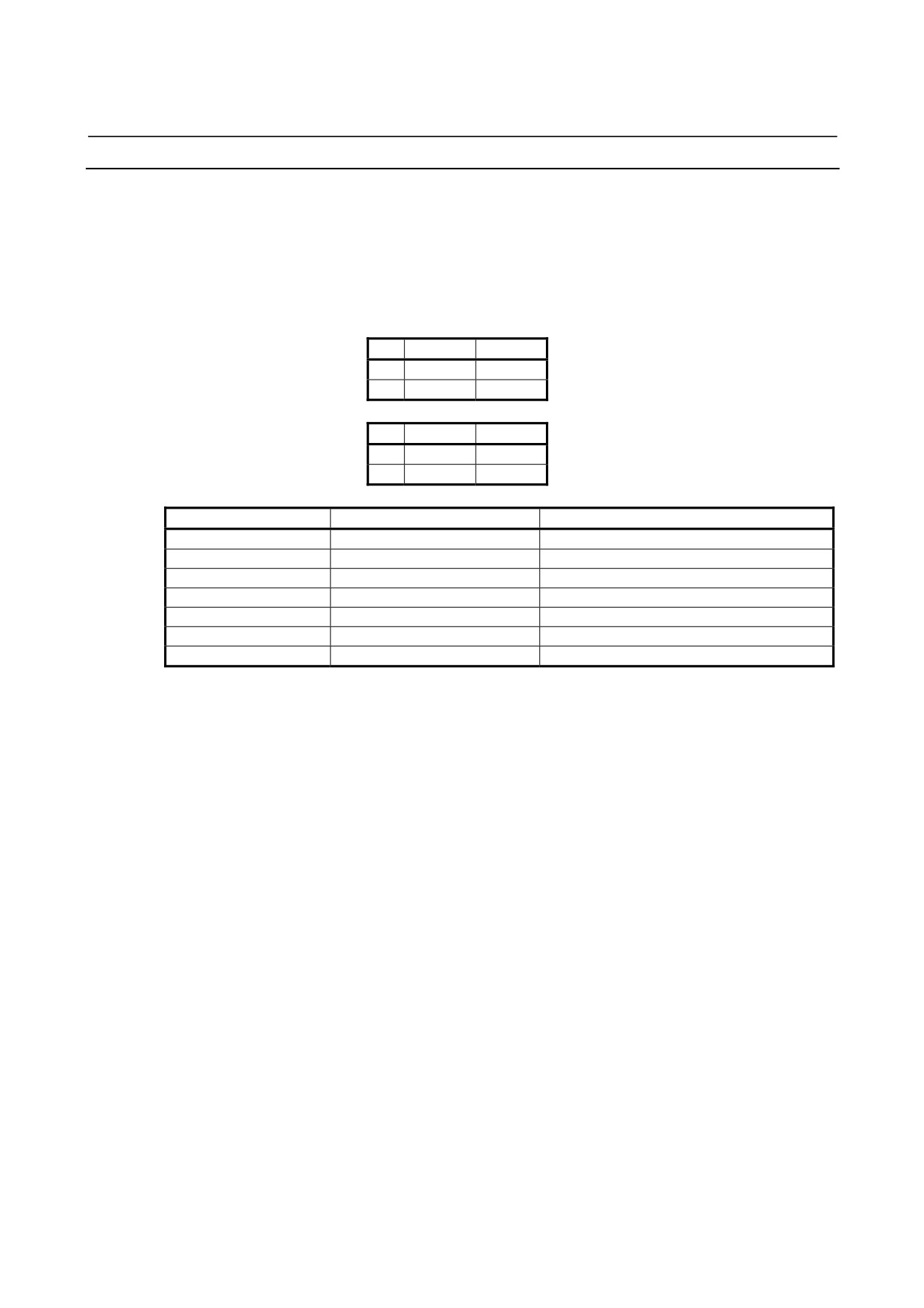
Parameter setting examples for a 2-path system
•
Parameter No.12600
Path 1
Path 2
X
101
201
Z
102
202
•
Parameter No.8180
Path 1
Path 2
X
0
0
Z
0
102
•
Program example (M100 to M103 are synchronization M codes.)
Path 1
Path 2
Operation
N10 M100 ;
M100 ;
Synchronization between paths 1 and 2
N20 G51.4 P102 Q202 ;
Start of Z1-Z2 synchronous control
N30 M101 ;
M101 ;
Synchronization between paths 1 and 2
N40 G00 Z100.;
Synchronous slave movement
Z1-Z2 synchronous control
N50 M102 ;
M102 ;
Synchronization between paths 1 and 2
N60 G50.4 Q202 ;
Cancellation of Z1-Z2 synchronous control
N70 M103 ;
M103 ;
Synchronization between paths 1 and 2
- Start of synchronous control
N20 G51.4 P102 Q202 : Start of synchronous control with the Z1-axis
being a master axis and the Z2-axis being a slave axis
- Cancellation of synchronous control
N60 G50.4 Q202 : Cancellation of synchronous control with the
Z1-axis being a master axis and the Z2-axis being a slave axis
- Parking
Use the L command to specify the start and cancellation of the parking
of synchronous axes.
If the L command is omitted or if the L0 command is issued, the
parking of both synchronous master axis and synchronous slave axis is
canceled.
- Parameter check
If the axis number corresponding to the P specified with G51.4 is not
set in slave axis parameter No. 8180, alarm PS5339 is issued.
- 346 -
B-64304EN-1/01
PROGRAMMING
7.AXIS CONTROL FUNCTIONS
Composite control
Composite control is performed with the G51.5/G50.5 commands,
instead of composite control axis selection signals.
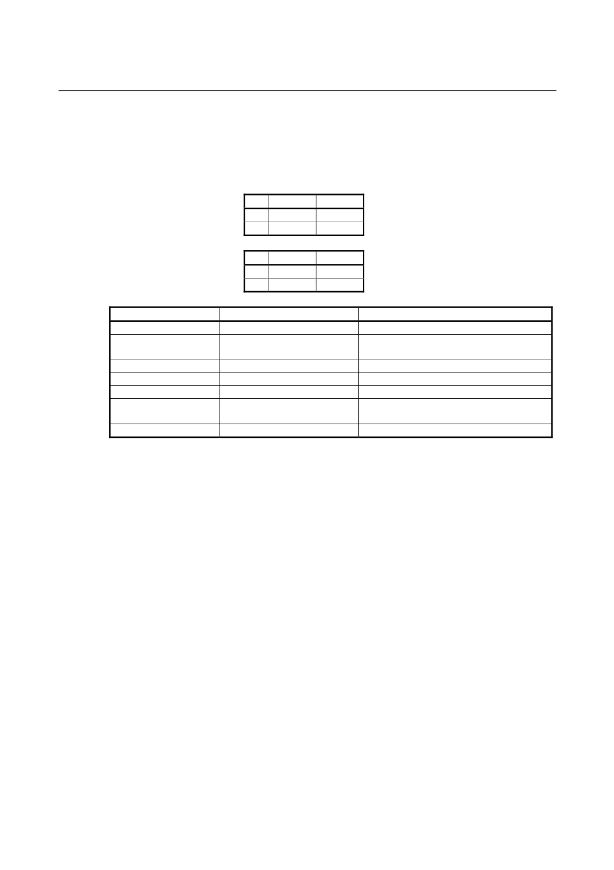
Parameter setting examples for a 2-path system
•
Parameter No.12600
Path 1
Path 2
X
101
201
Z
102
202
•
Parameter No.8183
Path 1
Path 2
X
0
101
Z
0
102
•
Program example (M100 to M103 are synchronization M codes.)
Path 1
Path 2
Operation
N10 M100 ;
M100 ;
Synchronization between paths 1 and 2
N20 G51.5 P101 Q201 ;
Start of X1-X2 composite control
N30 G51.5 P102 Q202 ;
Start of Z1-Z2 composite control
N40 M101 ;
M101 ;
Synchronization between paths 1 and 2
N50 G00 X 100. Z100.;
Composite movement
X1-X2 and Z1-Z2 composite control
N60 M102 ;
M102 ;
Synchronization between paths 1 and 2
N70 G50.5 P101 Q201 ;
Cancellation of X1-X2 composite control
N80 G50.5 P102 Q202 ;
Cancellation of Z1-Z2 composite control
N90 M103 ;
M103 ;
Synchronization between paths 1 and 2
- Start of composite control
N20 G51.5 P101 Q201 : Start of composite control on the X1- and
X2-axes
N30 G51.5 P102 Q202 : Start of composite control on the Z1- and
Z2-axes
- Cancellation of composite control
N70 G50.5 P101 Q201 : Cancellation of composite control on the X1-
and X2-axes
N80 G50.5 P102 Q202 : Cancellation of composite control on the Z1-
and Z2-axes
- Parameter check
If the composite control axis corresponding to the P or Q specified
with G51.5/G50.5 is not set in parameter No. 8183, alarm PS5339 is
issued.
- 347 -
7.AXIS CONTROL FUNCTIONS
PROGRAMMING
B-64304EN-1/01
Superimposed control
Superimposed control is performed with the G51.6/G50.6 commands,
instead of superimposed control axis selection signals.
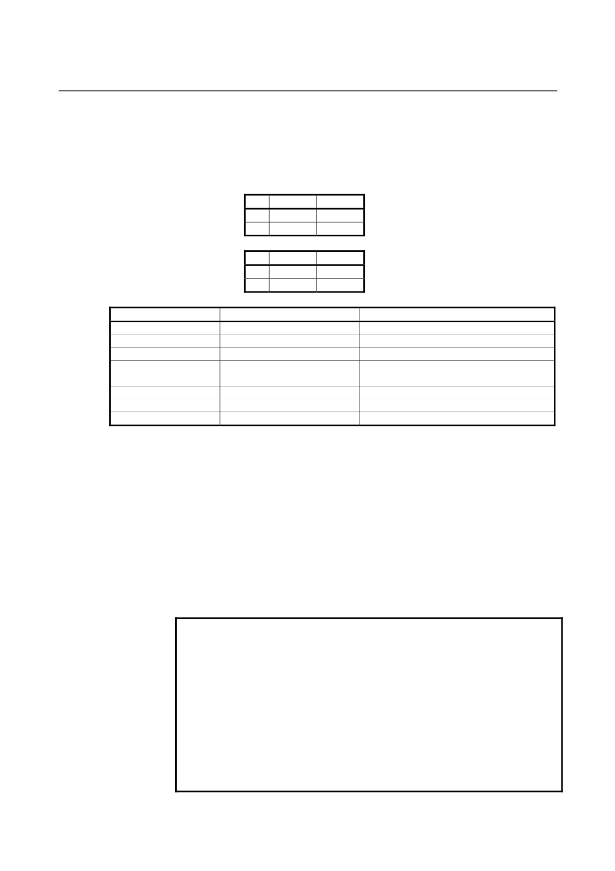
Parameter setting examples for a 2-path system
•
Parameter No.12600
Path 1
Path 2
X
101
201
Z
102
202
•
Parameter No.8186
Path 1
Path 2
X
0
0
Z
0
0
•
Program example (M100 to M103 are synchronization M codes.)
Path 1
Path 2
Operation
N10 M100 ;
M100 ;
Synchronization between paths 1 and 3
N20 G51.6 P102 Q202 ;
Start of Z1-Z2 superimposed control
N30 M101 ;
M101 ;
Synchronization between paths 1 and 3
N40 G00 Z100.;
G00 Z-200.;
Z1-Z2 superimposed control
(Z+100 superimposed on Z2)
N50 M102 ;
M102 ;
Synchronization between paths 1 and 3
N60 G50.6 Q202 ;
Cancellation of Z1-Z2 superimposed control
N70 M103 ;
M103 ;
Synchronization between paths 1 and 3
- Start of superimposed control
N20 G51.6 P102 Q202 : Start of superimposed control with the
Z1-axis being a master axis and the Z2-axis being a slave axis
- Cancellation of superimposed control
N60 G50.6 Q202 : Cancellation of superimposed control with the
Z1-axis being a master axis and the Z2-axis being a slave axis
- Parameter check
If the axis number corresponding to the P specified with G51.6 is not
set in superimposed slave axis parameter No. 8186, alarm PS5339 is
issued.
NOTE
1 If G codes (G50.4/G50.5/G50.6) for canceling synchronous,
composite, and superimposed control with program commands
are issued for axes under synchronous, composite, and
superimposed control with DI signals, synchronous, composite,
and superimposed control is canceled.
2 If the synchronous control axis selection signal, composite
control axis selection signal, and superimposed control axis
selection signal are changed from '1' to '0' for axes under
synchronous, composite, and superimposed control with
program commands, synchronous, composite, and
superimposed control is canceled.
- 348 -
B-64304EN-1/01
PROGRAMMING
8.2-PATH CONTROL FUNCTION
8
2-PATH CONTROL FUNCTION
Chapter
8, "2-PATH CONTROL FUNCTION", consists of the
following sections:
8.1
OVERVIEW
350
8.2
WAITING FUNCTION FOR PATHS
351
8.3
COMMON MEMORY BETWEEN EACH PATH
352
8.4
SPINDLE CONTROL BETWEEN EACH PATH
354
8.5
SYNCHRONOUS/COMPOSITE/SUPERIMPOSED
CONTROL
355
8.6
BALANCE CUT (G68, G69)
358
- 349 -
8.2-PATH CONTROL FUNCTION PROGRAMMING
B-64304EN-1/01
8.1
OVERVIEW
The 2-path control function is intended to perform two types of
machining simultaneously and independently. The function applies
to lathes and automatic lathes with which two tool posts operate
simultaneously to machine one workpiece.
To control two paths to machine one workpiece simultaneously, the
machining program for each path is stored in the program memory for
the path. In automatic operation, this function selects the program
for path 1 and that for path 2 from the program memory for the
relevant path. When the paths are activated, the programs selected
for the relevant tool posts are executed simultaneously and
independently.
To make tool posts 1 and 2 synchronous during machining, the
waiting function can be used.
Other functions specific to 2-path control that include the following
functions can also be used: Interference check for each path, balance
cutting, synchronous/composite/superimposed control, spindle control
between each path, and common memory between each path.
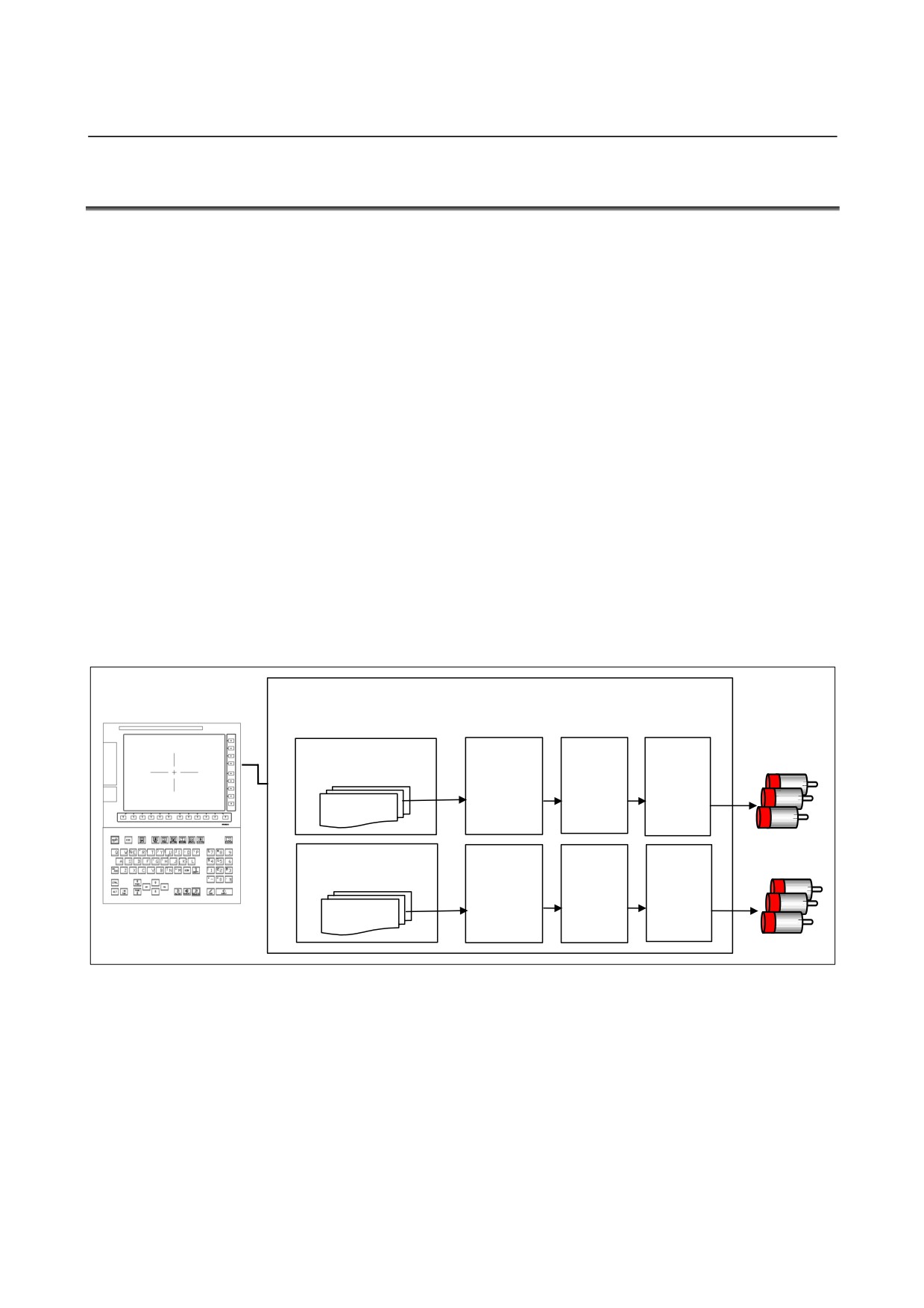
Only one LCD/MDI is provided for two paths. The path selection
signal is used to switch LCD/MDI operation or display between paths
1 and 2.
For a system with two paths
CNC
LCD/MDI
Program memory for
Path 1
Path 1
Path 1
path 1
program
position
axis
analysis
control
control
Programs
Program memory for
Path 2
Path 2
Path 2
path 2
program
position
axis
analysis
control
control
Programs
- 350 -
B-64304EN-1/01
PROGRAMMING
8.2-PATH CONTROL FUNCTION
8.2
WAITING FUNCTION FOR PATHS
Overview
Control based on M codes is used to cause one path to wait for the
other during machining. When an M code for waiting is specified in
a block for one path during automatic operation, the another path
waits for the same M code to be specified before staring the execution
of the next block.
A range of M codes used as M codes for waiting is to be set in the
parameters
(Nos.
8110 and
8111) beforehand. Waiting can be
ignored using a signal.
Format
Mm ;
m: Number of an M code for waiting
Explanation
CAUTION
1 An M code for waiting must always be specified in a
single block.
2 Unlike other M codes, the M code for waiting is not
output to the PMC.
3 If the operation of a single path is required, the M
code for waiting need not be deleted. By using the
signal to specify that waiting be ignored (NOWT),
the M code for waiting in a machining program can
be ignored. For details, refer to the manual
supplied by the machine tool builder.
4 If using a waiting M code in 1 block multiple-M code
command, be sure to specify it as the first M code.
- 351 -
8.2-PATH CONTROL FUNCTION PROGRAMMING
B-64304EN-1/01
8.3
COMMON MEMORY BETWEEN EACH PATH
Overview
In a 2-path system, this function enables data within the specified
range to be accessed as data common to both paths. The data
includes tool compensation memory and custom macro common
variables.
Explanation
The path common memory function enables the following operations.
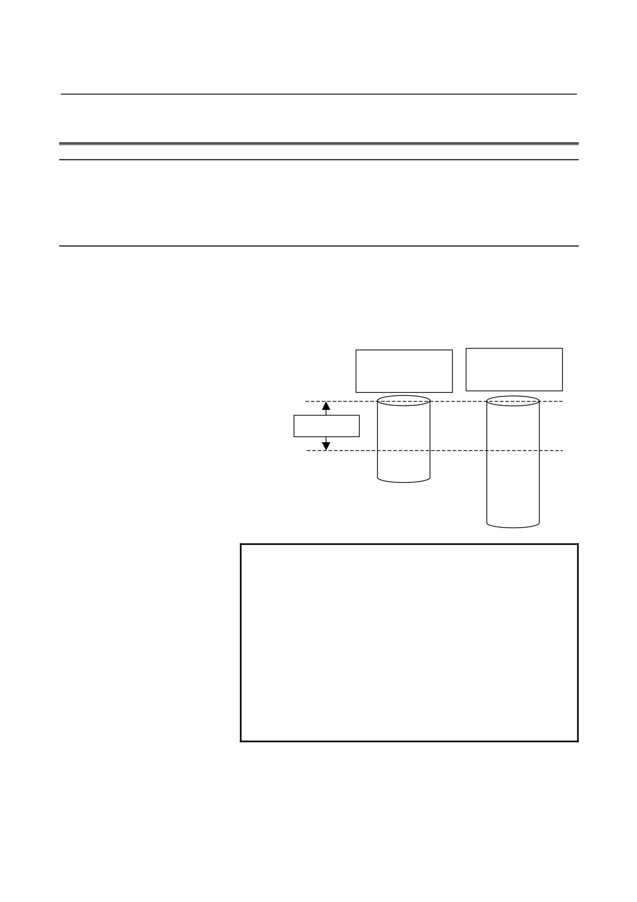
- Tool compensation memory
Part or all of tool compensation memory for individual paths can be
used as common data by setting parameter No. 5029.
Tool offset pairs of
Tool offset pairs of
path 1
path 2
Tool
compensation
number 1
No.5029=20
80 tool
120 tool
offset
offset
Tool
pairs
pairs
compensation
number 20
NOTE
1 The same unit for tool compensation (bits 0 and 1
of parameter No. 5042) must be set for both paths.
2 Set a value less than the number of tool
compensation values for each path for parameter
No. 5029.
3 When the setting of parameter No. 5029 exceeds
the number of tool compensation values for each
path, the smaller of the numbers of tool
compensation values for both paths is used as a
common number.
4 For details, refer to the relevant manual of the
machine tool builder.
- 352 -
B-64304EN-1/01
PROGRAMMING
8.2-PATH CONTROL FUNCTION
- Custom macro common variables
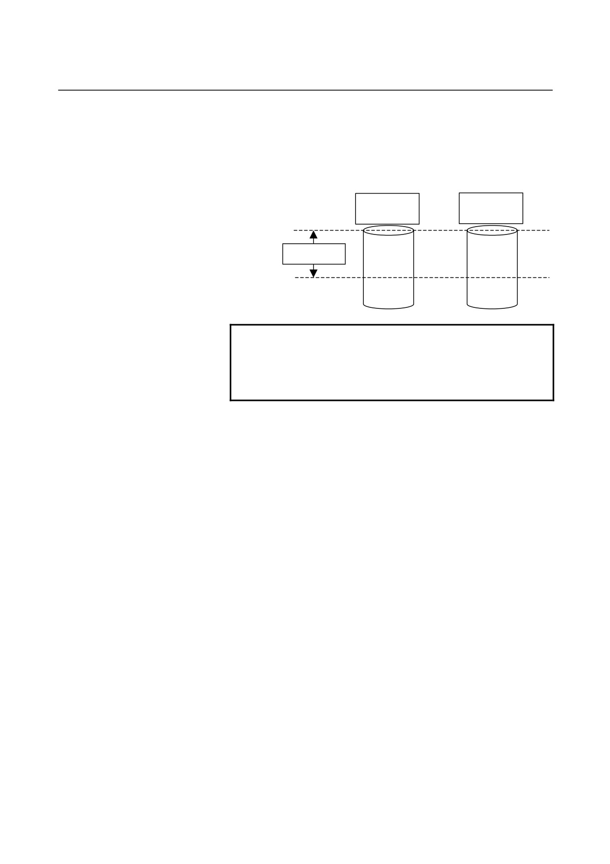
All or part of custom macro common variables #100 to #199 and #500
to #999 can be used as common data by setting parameters No. 6036
(#100 to #199) and 6037 (#500 to #999).
Macro variables
Macro variables
for path 1
for path 2
Macro variable number
No.6036=20
100
100
macro
macro
Macro variable number 119
variables
variables
NOTE
If the value of parameter No. 6036 or 6037 exceeds
the maximum number of custom macro common
variables, the maximum number of custom macro
common variables is assumed.
- 353 -
8.2-PATH CONTROL FUNCTION PROGRAMMING
B-64304EN-1/01
8.4
SPINDLE CONTROL BETWEEN EACH PATH
Overview
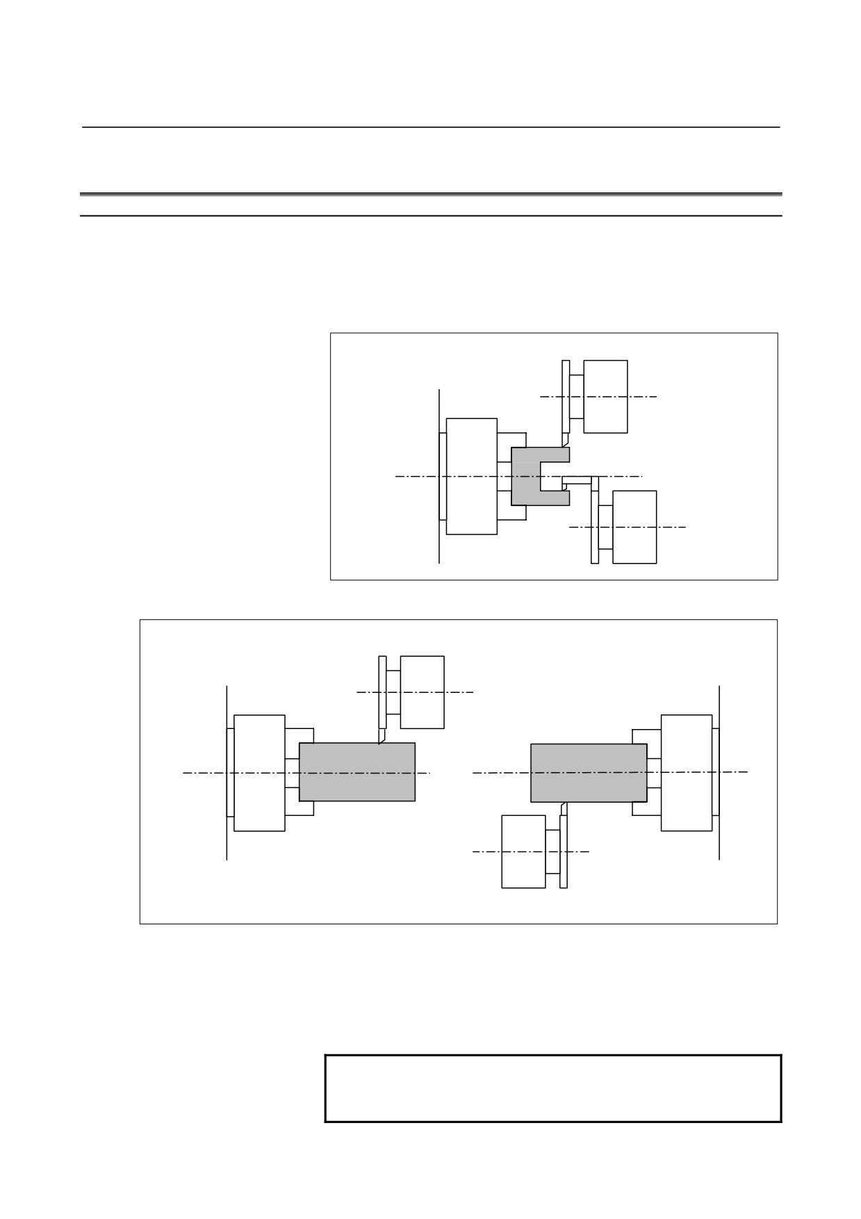
This function allows a workpiece attached to one spindle to be
machined simultaneously with two tool posts and each of two
workpieces attached to each of two spindles to be machined
simultaneously with each of two tool posts.
Tool post 1
Spindle
Tool post 2
Fig. 8.4 (a) Application to a lathe with one spindle and two tool posts
¥
Tool post 1
Spindle 1
Spindle 2
Tool post 2
Fig. 8.4 (b) Application to a lathe with two spindles and two tool posts
The spindle belonging to each path can generally be controlled by
programmed commands for the path. With path spindle command
selection signals, programmed commands for any path can control the
spindle belonging to any path.
NOTE
For the method of spindle command selection, refer
to the relevant manual of the machine tool builder.
- 354 -
B-64304EN-1/01
PROGRAMMING
8.2-PATH CONTROL FUNCTION
8.5
SYNCHRONOUS/COMPOSITE/SUPERIMPOSED
CONTROL
Overview
In 2-path control, the synchronous control function, composite control
function, and superimposed control function enable synchronous
control, composite control, and superimposed control in a single path
system or between 2-path systems.
Explanation
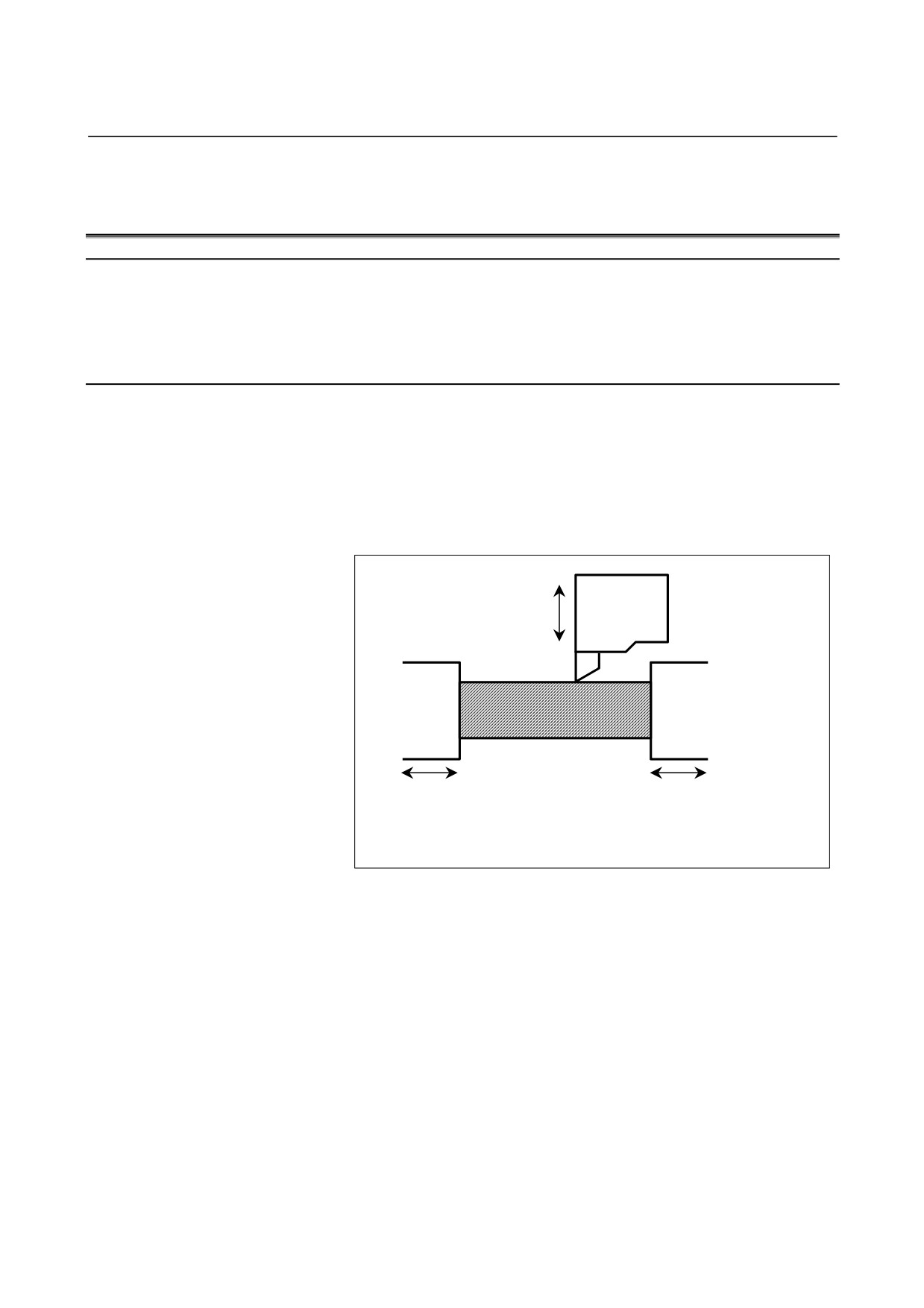
- Synchronous control
• Synchronizes movement along an axis of one system with that
along an axis of the another path.
Example)
Synchronizing movement along the Z1 (master) and Z2 (slave)
axes
Turret 1
X1
Workpiece
Z1
Z2 (Synchronized with
movement along the Z1 axis)
Machining according to a program for path 1
- 355 -
8.2-PATH CONTROL FUNCTION PROGRAMMING
B-64304EN-1/01
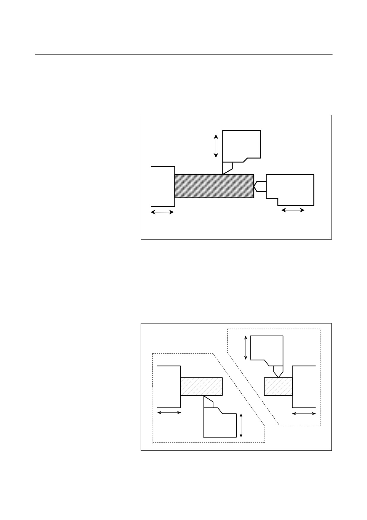
• Synchronizes movement along an axis of one path with that along
another axis of the same path.
Example)
Synchronizing movement along the Z1 (master) and B1 (slave)
axes
Turret 1
X1
Tail stock
Workpiece 1
B1 (Synchronized with
Z1
movement along the Z1
axis)
- Composite control
• Exchanges the move commands for different axes of different path.
Example)
Exchanging the commands for the X1 and X2 axes
→ Upon the execution of a command programmed for path 1,
movement is performed along the X2 and Z1 axes.
Upon the execution of a command programmed for path 2,
movement is performed along the X1 and Z2 axes.
Machining according to a program
Turret 1
X1
for path 1
Workpiece 1
Workpiece 2
Z1
Z2
X2
Turret 1
Machining according to
a program for path 2
- 356 -
B-64304EN-1/01
PROGRAMMING
8.2-PATH CONTROL FUNCTION
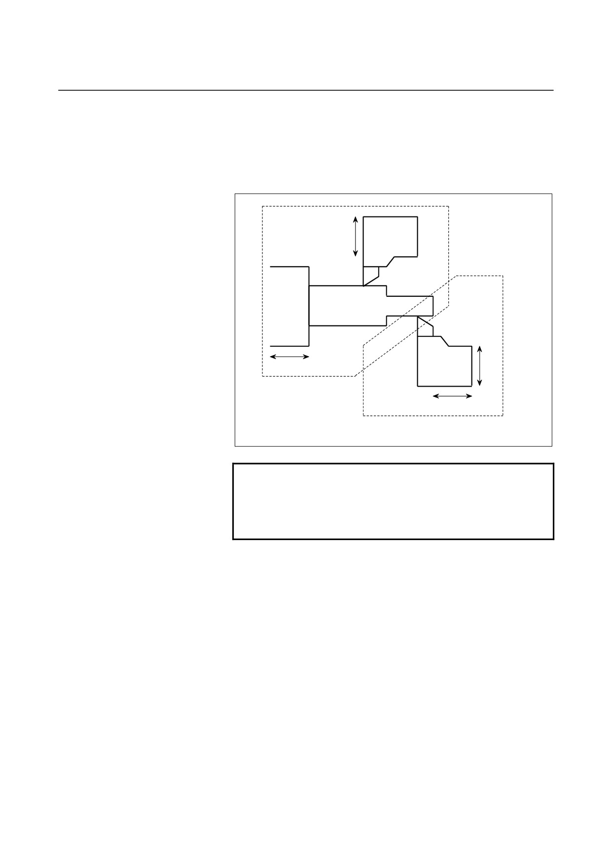
- Superimposed control
• Provides a move command of an axis for a different axis in another
path.
Example)
Providing the Z2 (slave) axis with a move command specified
for the Z1 (master) axis
Turret 1
Machining according to
X1
a program for path 1
Workpiece 1
Z1
X2
Turret 2
Z2
Machining according to a program
for path 2
NOTE
The method used to specify synchronous,
composite, or superimposed control varies with the
machine tool builder. For details, refer to the
manual supplied by the machine tool builder.
- 357 -
8.2-PATH CONTROL FUNCTION PROGRAMMING
B-64304EN-1/01
8.6
BALANCE CUT (G68, G69)
Overview
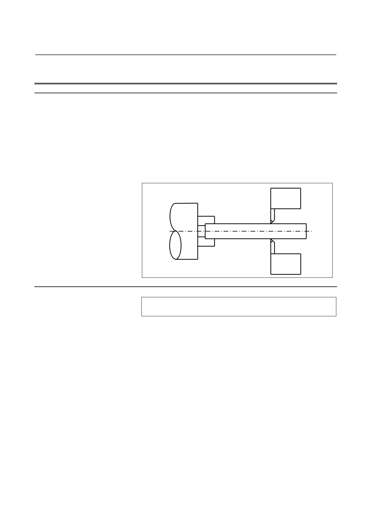
When a thin workpiece is to be machined as shown below, a precision
machining can be achieved by machining each side of the workpiece
with a tool simultaneously; this function can prevent the workpiece
from warpage that can result when only one side is machined at a time
(see the figure below). When both sides are machined at the same
time, the movement of one tool must be in phase with that of the other
tool.
Otherwise, the workpiece can vibrate, resulting in poor
machining. With this function, the movement of one tool post can be
easily synchronized with that of the other tool post.
Tool post 2
Tool post 1
Format
G68 ; Balance cut mode on
G69 ; Balance cut mode cancel
- 358 -
B-64304EN-1/01
PROGRAMMING
8.2-PATH CONTROL FUNCTION
Explanation
When G68 is specified in the programs for tool posts 1 and 2, the
balance cut mode is set to on. When G69 is specified, the balance
cut mode is canceled.
When G68 or G69 is specified for either tool post, the tool post waits
until G68 or G69 is specified for the other tool post.
In the balance cut mode, balance cutting is performed when a move
command in cutting feed is specified for both tool posts.
In balance cutting, the tool posts start moving simultaneously in each
block in which a move command in cutting feed is specified.
Specify G68 or G69 in a single block.
NOTE
1 Balance cutting is not performed in dry run or
machine lock state. G68 or G69 specified for one
tool post is synchronized with G68 or G69 specified
for the other tool post, however.
2 In the balance cut mode, G68 specified for one tool
post is not synchronized with G68 specified for the
other tool post. In the balance cut cancel mode,
G69 specified for one tool post is not synchronized
with G69 specified for the other tool post.
3 Balance cutting is not performed in a block in which
0 is specified for the travel distance.
4 Balance cutting is not performed when rapid
traverse is specified.
- 359 -
8.2-PATH CONTROL FUNCTION PROGRAMMING
B-64304EN-1/01
Caution
CAUTION
1 Balance cut only starts cutting feed on both tool
posts at the same time; it does not maintain
synchronization thereafter. To synchronize all the
movements of both tool posts, the setting for both
tool posts, such as the travel distance and feedrate,
must be the same. Override and interlock can be
applied independently to both tool posts. The
settings for both tool posts that are related to
override and interlock must also be the same to
perform balance cutting.
2 After feed hold is applied during execution of
balance cutting for both tool posts, balance cutting
is not performed at the restart. Balance cutting is
performed when the next move command is
executed for both tool posts.
NOTE
1 Time delay before the pulse distribution of both tool
posts is started is 2 msec or shorter.
2 Overlap is invalid. In the balance cut mode,
synchronization is established at the start of each
move block in which cutting is specified, so
movement can momentarily stop.
3 In the balance cut mode, continuous thread cutting
overlap is also invalid. Perform continuous thread
cutting in the balance cut cancel mode.
4 To establish synchronization of the pulse
distribution in a block in which thread cutting is
specified, the same position coder must be
selected.
5 The cancel mode (G69) is unconditionally set by a
reset.
6 When the option "mirror image for double turret" is
selected, the balance cut function cannot be used.
To use the option “mirror image for double turret”,
set bit 0 (NVC) of parameter No. 8137 to 0 to
disable the balance cut function.
- 360 -
III. OPERATION
B-64304EN-1/01
OPERATION
1.DATA INPUT/OUTPUT
1
DATA INPUT/OUTPUT
By using the memory card interface on the left side of the display,
information written in a memory card is read into the CNC and
information is written from the CNC to a memory card.
The following types of data can be input and output:
1. Y-axis offset data
The above data can be input and output on the screens used for
displaying and setting the data and on the ALL IO screen.
Chapter
1, "DATA INPUT/OUTPUT", consists of the following
sections:
1.1 INPUT/OUTPUT ON EACH SCREEN
364
1.1.1 Inputting and Outputting Y-axis Offset Data
364
1.1.1.1 Inputting Y-axis offset data
364
1.1.1.2 Outputting Y-axis Offset Data
365
1.2 INPUT/OUTPUT ON THE ALL IO SCREEN
366
1.2.1 Inputting and Outputting Y-axis Offset Data
367
- 363 -
1.DATA INPUT/OUTPUT
OPERATION
B-64304EN-1/01
1.1
INPUT/OUTPUT ON EACH SCREEN
Data can be input to and output from the Y-axis offset screens.
1.1.1
Inputting and Outputting Y-axis Offset Data
1.1.1.1 Inputting Y-axis offset data
Y-axis offset data is loaded into the memory of the CNC from a
memory card. The input format is the same as the output format.
The Y-axis offset data that is registered in the memory and has a
corresponding data number is replaced with data input by this
operation.
Inputting Y-axis offset data (for 8.4/10.4-inch display unit)
Procedure
1
Make sure the input device is ready for reading.
2
Press the EDIT switch on the machine operator’s panel.
3
Press function key
4
Press the continuous menu key
several times until soft key
[Y OFFSET] appears.
5
Press soft key [Y OFFSET] to display the Y-axis offset data.
screen.
6
Press soft key [(OPRT)].
7
Press the continuous menu key
several times until soft key
[F INPUT] appears.
8
Press soft key [F INPUT].
9
Type the name of the file that you want to input.
If the input file name is omitted, default input file name
"TOOLOFST.TXT" is assumed.
10 Press soft key [EXEC].
This starts reading the Y-axis offset data, and "INPUT" blinks in
the lower right part of the screen. When the read operation ends,
the "INPUT" indication disappears.
To cancel the input, press soft key [CANCEL].
- 364 -
B-64304EN-1/01
OPERATION
1.DATA INPUT/OUTPUT
1.1.1.2 Outputting Y-axis Offset Data
Y-axis offset data is output in a output format from the memory of the
CNC to a memory card.
Outputting Y-axis offset data (for 8.4/10.4-inch display unit)
Procedure
1
Make sure the output device is ready for outputting.
2
Press the EDIT switch on the machine operator’s panel.
3
Press function key
4
Press the continuous menu key
several times until soft key
[Y OFFSET] appears.
5
Press soft key [Y OFFSET] to display the Y-axis offset data.
screen.
6
Press soft key [(OPRT)].
7
Press the continuous menu key
several times until soft key
[F OUTPUT] appears.
8
Press soft key [F OUTPUT].
9
Type the file name that you want to output.
If the file name is omitted, default file name "TOOLOFST.TXT"
is assumed.
10 Press soft key [EXEC].
This starts outputting the Y-axis offset data, and “OUTPUT”
blinks in the lower right part of the screen. When the read
operation ends, the “OUTPUT” indication disappears.
To cancel the output, press soft key [CANCEL].
- 365 -
1.DATA INPUT/OUTPUT
OPERATION
B-64304EN-1/01
1.2
INPUT/OUTPUT ON THE ALL IO SCREEN
Just by using the ALL IO screen, you can input and output Y-axis
offset data and tool offset / 2nd geometry data.
The following explains how to display the ALL IO screen:
Displaying the ALL IO screen (for 8.4/10.4-inch display unit)
Procedure
1 Press function key
2 Press the continuous menu key
several times until soft key
[ALL IO] is displayed..
3 Press soft key [ALL IO] to display the ALL IO screen.
The subsequent steps to select data from the ALL IO screen will be
explained for each type of data.
- 366 -

B-64304EN-1/01
OPERATION
1.DATA INPUT/OUTPUT
1.2.1
Inputting and Outputting Y-axis Offset Data
With the lathe system, Y-axis offset data can be input and output
using the ALL IO screen.
Inputting Y-axis offset data (for 8.4/10.4-inch display unit)
Procedure
1
On the ALL IO screen, press the continuous menu key
several times until soft key [Y OFFSET] is displayed.
2
Press soft key [Y OFFSET].
3
Select EDIT mode.
4
Press soft key [(OPRT)].
5
Press soft key [N INPUT].
6
Set the name of the file that you want to input.
Type a file name, and press soft key [F NAME].
If the input file name is omitted, default file name
"TOOLOFST.TXT" is assumed.
7
Press soft key [EXEC].
This starts reading the Y-axis offset data, and "INPUT" blinks in
the lower right part of the screen. When the read operation ends,
the "INPUT" indication disappears.
To cancel the input, press soft key [CANCEL].
Outputting Y-axis offset data (for 8.4/10.4-inch display unit)
Procedure
1
On the ALL IO screen, press the continuous menu key
several times until soft key [Y OFFSET] is displayed.
2
Press soft key [Y OFFSET].
3
Select EDIT mode.
4
Press soft key [(OPRT)].
5
Press soft key [F OUTPUT].
6
Set the file name to be output.
Type a file name, and press soft key [F NAME].
If the file name is omitted, default file name "TOOLOFST.TXT"
is assumed.
7
Press soft key [EXEC].
This starts outputting the Y-axis offset data, and “OUTPUT”
blinks in the lower right part of the screen. When the read
operation ends, the “OUTPUT” indication disappears.
To cancel the output, press soft key [CANCEL].
- 367 -
2.SETTING AND DISPLAYING DATA OPERATION
B-64304EN-1/01
2
SETTING AND DISPLAYING DATA
Chapter 2, "SETTING AND DISPLAYING DATA", consists of the
following sections:
2.1 SCREENS DISPLAYED BY FUNCTION KEY
..........369
2.1.1 Setting and Displaying the Tool Offset Value
370
2.1.2 Direct Input of Tool Offset Value
374
2.1.3 Direct Input of Tool Offset Value Measured B
376
2.1.4 Counter Input of Offset value
379
2.1.5 Setting the Workpiece Coordinate System Shift Value380
2.1.6 Setting the Y-Axis Offset
382
2.1.7 Chuck and Tail Stock Barriers
385
- 368 -
B-64304EN-1/01
OPERATION
2.SETTING AND DISPLAYING DATA
2.1
SCREENS DISPLAYED BY FUNCTION KEY
Press function key
to display or set tool compensation values
and other data.
This section explains the display and setting of the following data
items:
1.
Tool offset value
2.
Workpiece coordinate system shift value
3.
Y-axis offset value
4.
Chuck and tail stock barriers
For the display and setting of data other than the above, refer to
“USER’S MANUAL (Common to Lathe System/Machining Center
System)” (B-64304EN).
- 369 -
2.SETTING AND DISPLAYING DATA OPERATION
B-64304EN-1/01
2.1.1
Setting and Displaying the Tool Offset Value
Dedicated screens are provided for displaying and setting tool offset
values and tool nose radius compensation values.
Whether to use tool geometry and wear compensation can be selected
using bit 6 (NGW) of parameter No. 8136; whether to use tool nose
radius compensation can be selected using bit 7 (NCR) of parameter
No. 8136.
(0: Use the function./1: Does not use the function.)
Setting and displaying the tool offset value and the tool nose radius compensation
value
Procedure
1
Press function key
When using a 2-path system, select, in advance, a path for which
a tool offset value is to be set, by using the path selection switch.
2
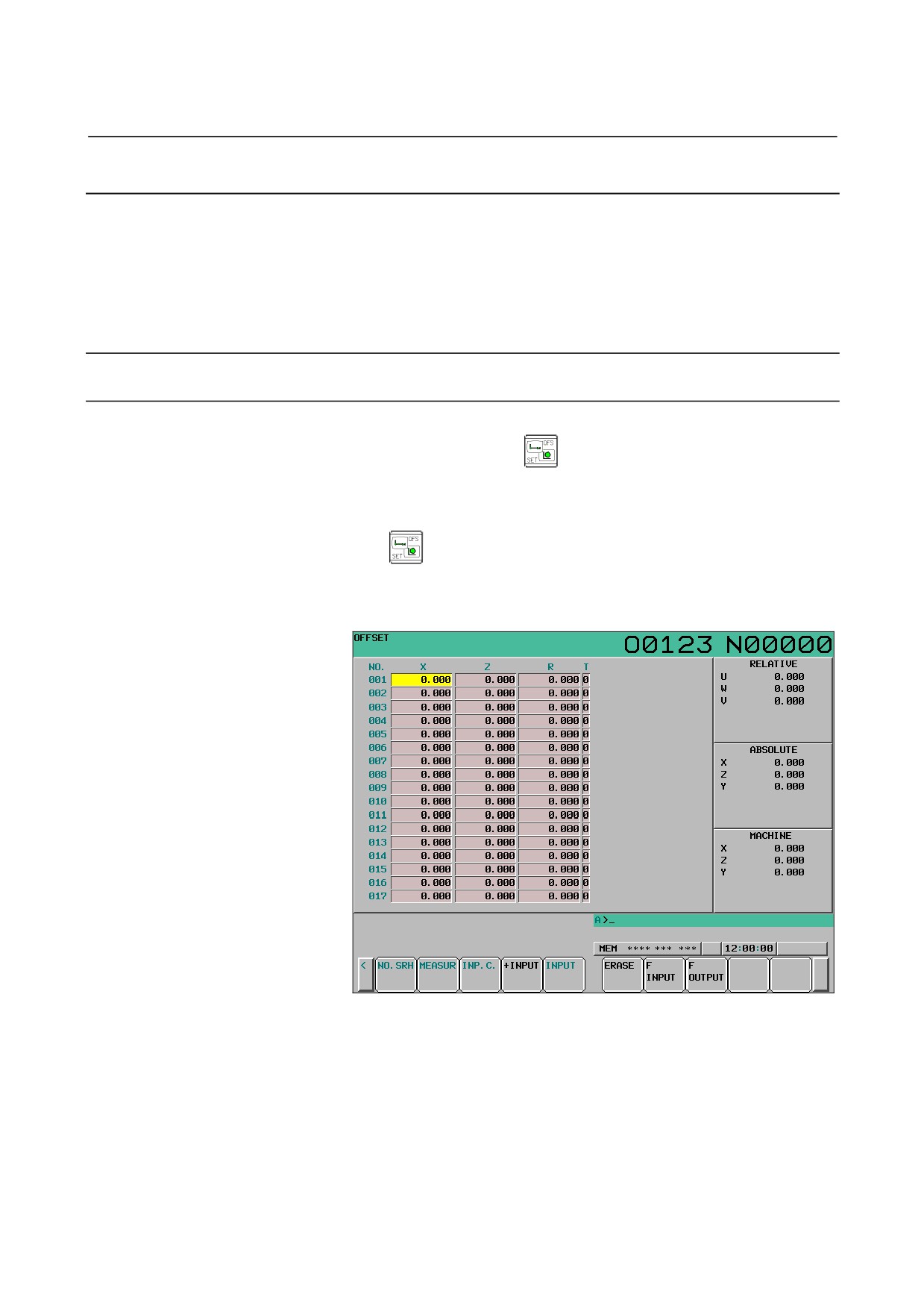
Press chapter selection soft key [OFFSET] or press function key
several times until the tool compensation screen is
displayed.
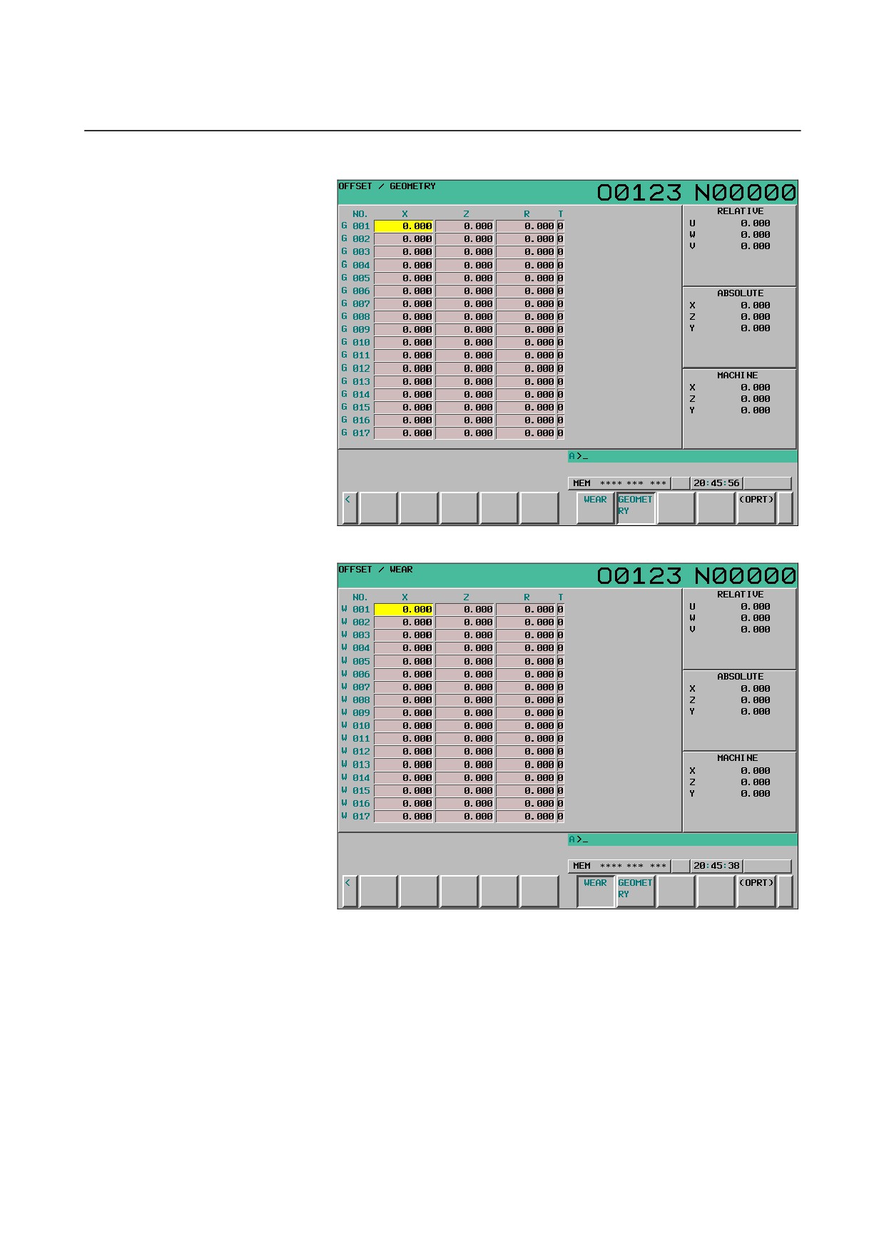
Different screens are displayed depending on whether tool
geometry offset, wear offset, or neither is applied.
Fig. 2.1.1 (a) When tool geometry/wear offset is not used (10.4-inch)
- 370 -
B-64304EN-1/01
OPERATION
2.SETTING AND DISPLAYING DATA
Fig. 2.1.1 (b) With tool geometry offset (10.4-inch)
Fig. 2.1.1 (c) With tool wear offset (10.4-inch)
3
Move the cursor to the compensation value to be set or changed
using page keys and cursor keys, or enter the compensation
number for the compensation value to be set or changed and
press soft key [NO.SRH].
4
To set a compensation value, enter a value and press soft key
[INPUT]. To change the compensation value, enter a value to
add to the current value (a negative value to reduce the current
value) and press soft key [+INPUT].
T (TIP) is the number of the imaginary tool nose.
T may be specified on the geometry compensation screen or on
the wear compensation screen.
- 371 -
2.SETTING AND DISPLAYING DATA OPERATION
B-64304EN-1/01
When tool nose radius compensation is not used (bit 7 (NCR) of
parameter No.
8136 is set to
1), neither radius nor T
(TIP) is
displayed.
Explanation
- Decimal point input
A decimal point can be used when entering a compensation value.
- Other method
An external input/output device can be used to input or output a cutter
compensation value. See Chapter III-8 “Data Input/Output” in the
User’s Manual (Common to Lathe System/Machining Center System).
Tool length compensation values can be set using the following
functions described in subsequent subsections: direct input of tool
offset value measured, direct input of tool offset value measured B,
and counter input of offset value.
- Number of tool compensation values
Up to 64 (1-path system) or 200 (2-path system) tool compensation
value sets are available.
When the function for 64 (1-path system) or 200 (2-path system) tool
compensation value sets is not used (bit 5 (NDO) of parameter No.
8136 to 1), up to 32 tool compensation value sets are available.
For each set, tool geometry offset can be distinguished from the tool
wear offset.
(When bit 6 (NGW) of parameter No. 8136 is set to 0)
- Disabling entry of compensation values
In some cases, tool wear compensation or tool geometry compensation
values cannot be input because of the settings in bits 0 (WOF) and 1
(GOF) of parameter No.3290. The number of the first tool offset
amount of which entry is to be disabled can be set for parameter No.
3294 and the number of tool offset amounts following the start
number can be set for parameter No. 3295 to disable entry of tool
offset amounts within the specified range from the MDI.
Consecutive input values are set as follows:
1)
When values are input for offset numbers, starting from one for
which input is not inhibited to one for which input is inhibited, a
warning is issued and values are set only for those offset
numbers for which input is not inhibited.
2)
When values are input for offset numbers, starting from one for
which input is inhibited to one for which input is not inhibited, a
warning is issued and no values are set.
- Displaying radius and T (TIP)
When tool nose radius compensation is not used according to the
setting, neither radius nor T (TIP) is displayed.
(Bit 7 (NCR) of
parameter No. 8136 is set to 1.)
- 372 -
B-64304EN-1/01
OPERATION
2.SETTING AND DISPLAYING DATA
- Changing offset values during automatic operation
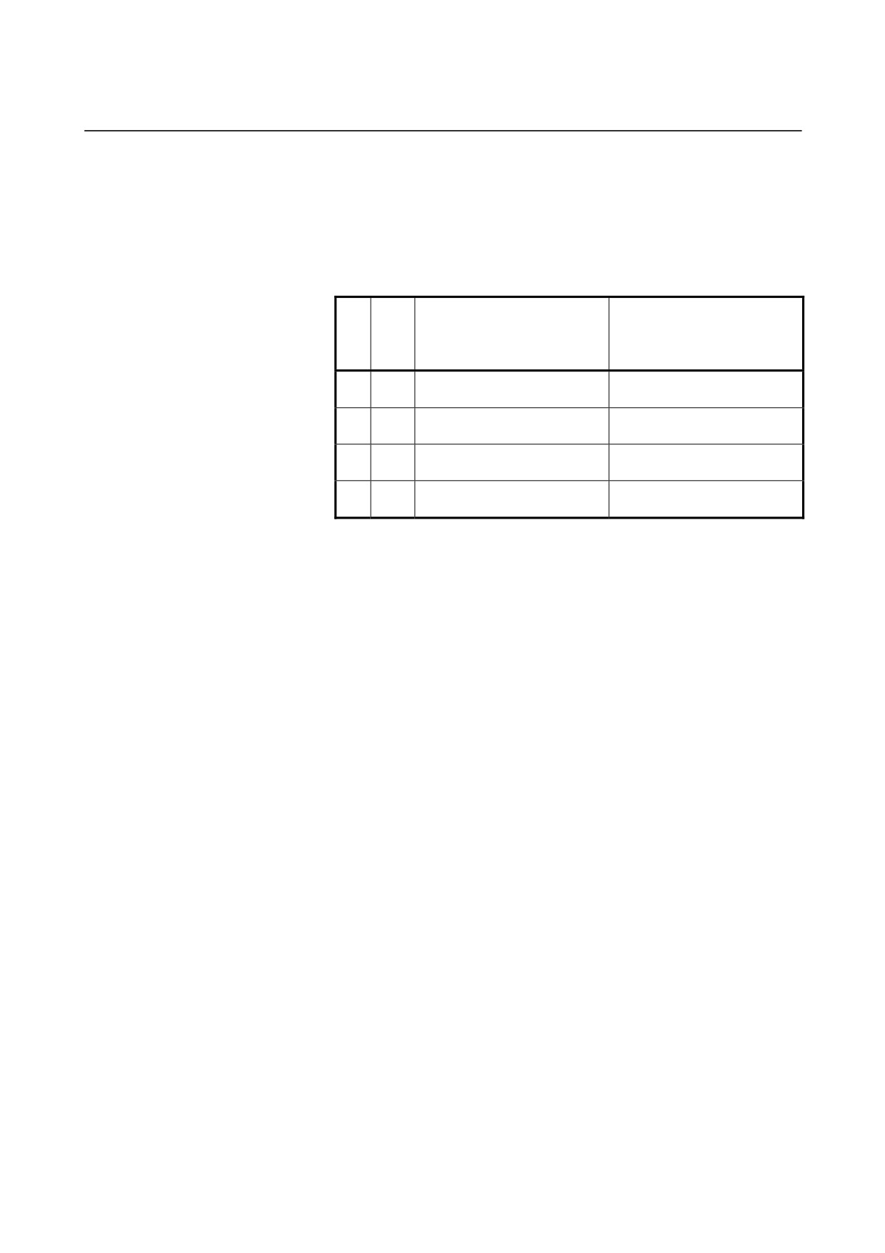
When offset values have been changed during automatic operation,
bits 4 (LGT) and 6 (LWM) of parameter No.5002 can be used for
specifying whether new offset values become valid in the next move
command or in the next T code command.
Fig. 2.1.1 (a)
When geometry
When geometry
compensation values and
compensation values and
LGT
LWM
wear compensation values
wear compensation values
are separately specified
are not separately specified
Become valid in the next T code
Become valid in the next T code
0
0
block
block
Become valid in the next T code
Become valid in the next T code
1
0
block
block
Become valid in the next T code
Become valid in the next move
0
1
block
command
Become valid in the next move
Become valid in the next move
1
1
command
command
- 373 -