FANUC Series 0i-MODEL C, Series 0i Mate-MODEL C. MAINTENANCE MANUAL - page 10
3. INPUT AND OUTPUT OF DATA
B-64115EN/02
6.
After the parameters have been input, set PARAMETER WRITE on
the SETTING screen to 0. Press
RESET
to release alram 100.
7.
Convenient method
1)
To change parameters in bit unit, press cursor key
or
,
then the cursor becomes bit length and you can set parameters bit
by bit (Bit parameter only).
2)
To set data consecutively, use
EOB
key.
(Ex.1)
1
2
3
4
EOB
4
5
6
7
EOB
9
9
9
9
INPUT
This key sequence sets data as follows:
0
1234
0
⇒
4567
0
9999
0
0
(Ex.2)
1
2
3
4
EOB
EOB
9
9
9
9
INPUT
This key sequence sets data as follows:
0
1234
0
⇒
0
0
9999
0
0
3)
To set the same data sequentially, press
=
(Ex.)
1
2
3
4
EOB
=
EOB
=
INPUT
This key sequence sets data as follows:
0
1234
0
⇒
1234
0
1234
0
0
4)
Bit parameters can be set as follows:
(Ex.)
1
1
EOB
=
EOB
=
INPUT
This key sequence sets data as follows:
0 0 0 0 0 0 0 0
0 0 0 1 1 0 0 0
0 0 0 0 0 0 0 0 ⇒
0 0 0 1 1 0 0 0
0 0 0 0 0 0 0 0
0 0 0 11 0 0 0
0 0 0 0 0 0 0 0
0 0 0 0 0 0 0 0
8.
After the required parameters are set, set PARAMETER WRITE to
0.
250
3. INPUT AND OUTPUT OF DATA
B-64115EN/02
The main CPU memorized the following data.
3.2
Outputting the data 1/O device while the CNC is rurnning normally
INPUTTING/
(1) CNC paramter
OUTPUTTING DATA
(2) PMC parameter
(3) Pitch error compensation amount
(4) Custom macro variable values
(5) Tool compensation amount
(6) Part program (machining program, custom macro program)
3.2.1
Be sure that data output cannot be done in an alarm status.
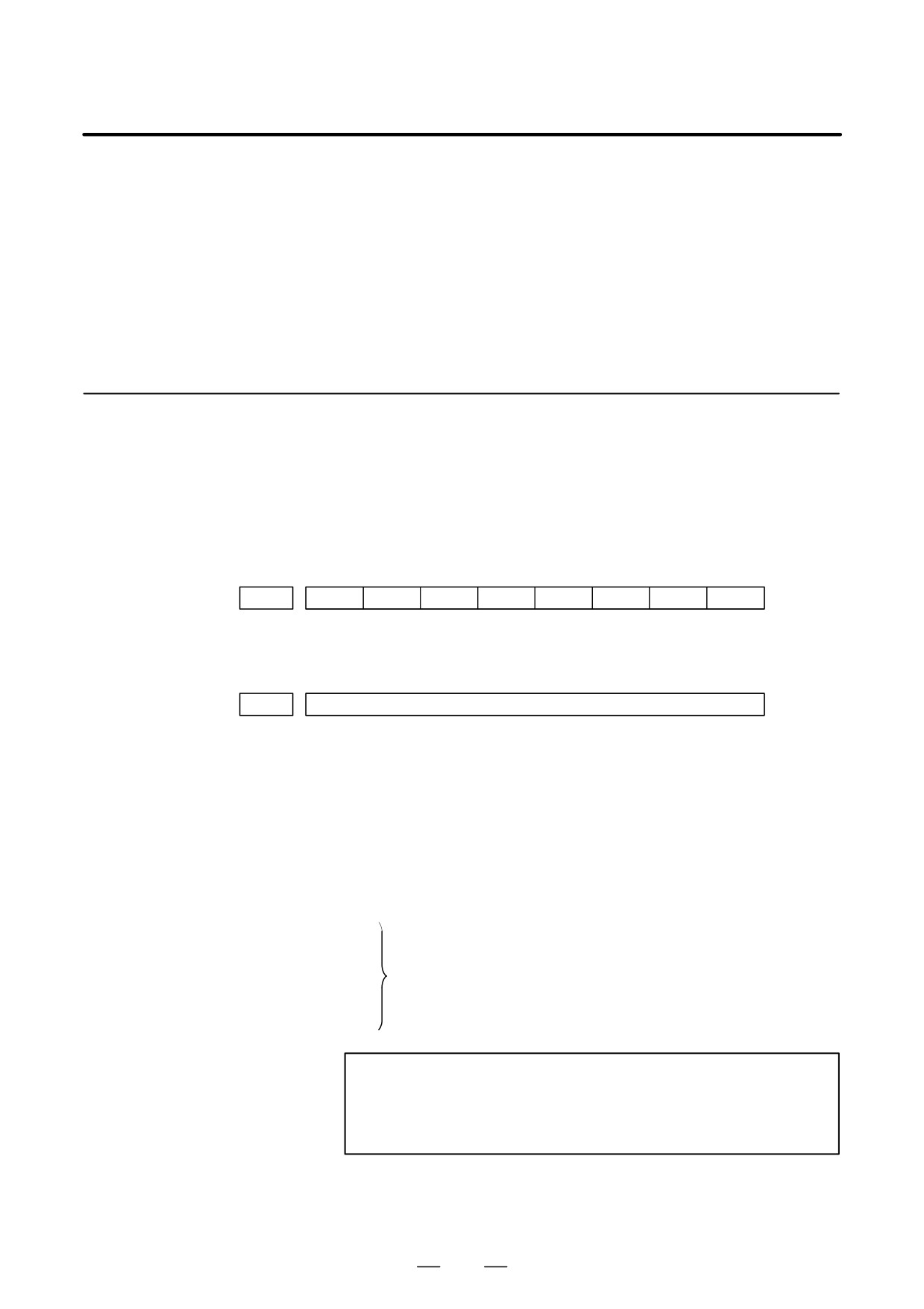
Parameters required for output are as follows :
Confirming the
In addition, l indicates the standard setting for input/output devices
Parameters Required
made by FANUC. Change these settings according to the unit you
for Data Output
actually use.
(Parameter can be changed in MDI mode or emergency stop status.)
#7
#6
#5
#4
#3
#2
#1
#0
0000
ISO
#1 (ISO)
0 : Output with EIA code
1 : Output with ISO code (FANUC cassette)
0020
Selection of I/O channel
l
0 : Channel 1 (JD36A of mother board)
1 : Channel 1 (JD36A of mother board)
2 : Channel 2 (JD36B of mother board)
4 : Memory card interface
5 : Data Server interface
6 : DNC operation or the M198 command is executed with
FOCAS1/Ethernet.
20
21
Data input/output is performed via the FANUC I/O Link
22
between the CNC and the Power Mate CNC in group n
|
(where n is from 0 to 15).
34
35
NOTE
An operation example shown here assumes that data input/
output is performed with an input/output unit connected to
the JD36A. (I/O channel = 0)
251
3. INPUT AND OUTPUT OF DATA
B-64115EN/02
#7
#6
#5
#4
#3
#2
#1
#0
0101
NFD
ASI
SB2
#7 (NFD)
0 : Feed is output when data is output.
1 : Feed is not output when data is output.
#3 (ASI)l
0 : EIA or ISO code is used for input/output data.
1 : ASCII code is used.
#0 (SB2)
0 : No. of stop bits is 1.
l
1 : No. of stop bits is 2.
0102
pecification number of input/output device
Set value
Input/output device
0
RS-232-C (Used control codes DC1 to DC4)
1
FANUC CASSETTE ADAPTOR 1 (FANUC CASSETTE B1/ B2)
2
FANUC CASSETTE ADAPTOR 3 (FANUC CASSETTE F1)
3
FANUC Handy File
4
RS-232-C (Not used control codes DC1 to DC4)
5
Portable tape reader
6
FANUC PPR
FANUC SYSTEM P-MODEL G, FANUC SYSTEM P-MODEL H
0103
Baud Rate
1:
50
5:
200
9:
2400
2:
100
6:
300
l10:
4800
3:
110
7:
600
11:
9600
4:
150
8:
1200
12:
19200 [BPS]
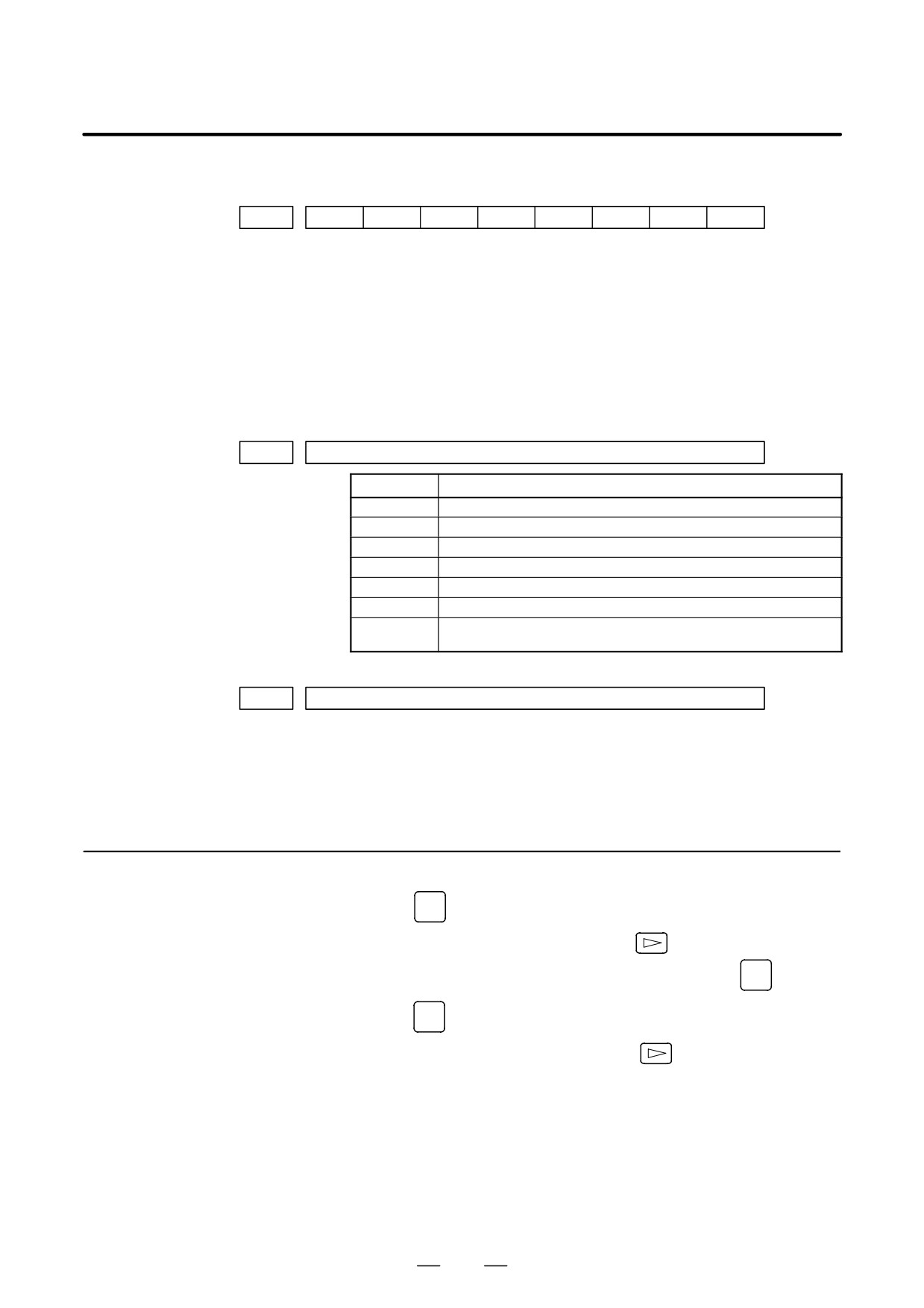
3.2.2
1. Enter EDIT mode or the emergency stop condition.
Outputting CNC
2. Press
PROG
key and soft key [PRGRM] to select a program text.
Parameters
3. Press soft key [(OPRT)] and soft key
And then, put out the head of file by pressing [FSRH]
0
[EXEC].
4. Press
SYSTEM
key and soft key [PARAM] to display parameter screen.
5. Press soft key [(OPRT)] ,and soft key
6. Press soft key [PUNCH] and [EXEC],and the parameters are started
to be output.
252
3. INPUT AND OUTPUT OF DATA
B-64115EN/02
3.2.3
1. Select MDI mode.
Outputting PMC
OFFSET
2. Press
SETTING
key then soft key [SETTING] to select a setting screen.
Parameters
3. Set the cursor to PARAMETER WRITE and input
1
and
INPUT
At this time, alarm 100 will be generated.
4. Press
SYSTEM
key and soft key [PMC].
5. Press soft key [PMCPRM] and then soft key [SETING] to display a
setting screen.
6. On the setting screen, set “PROGRAMMER ENABLE” to “YES” (bit
1 of K900/K17 = 1).
Thus, data input/output screen has been selected.
7. Select EDIT mode.
8. Press soft key
then key
9. Press soft key [I/O] and set the parameters on I/O.
Item selection cursor moves to the following item after data of an item
is set.
10.In CHANNEL NO item, input
1
INPUT
to select I/O channel 1.
11.In DEVICE item, press soft key [FDCAS] to select the floppy cassette.
12.In KIND DATA item, press soft key [PARAM].
13.In FUNCTION item, press soft key [WRITE].
14.In FILE No item, specify a file name. In this example input as follows:
@
P
M
C
INPUT
15.Press soft key [EXEC]. Then PMC parameters are started to be output.
16.After the PMC parameters have been output, set PARAMETER
WRITE to 0.
17.Press
RESET
to release alarm 100.
3.2.4
1. Select EDIT mode.
Outputting Pitch Error
SYSTEM
2. Press
key several times, press soft key [PARAM],
and
Compensation Amount
[PITCH] to select the SETTING screen for pitch error amount.
3. Press soft key [(OPRT)] and
4. Press soft key [PUNCH] and [EXEC], then pitch error compensation
amount is started to be output.
253
3. INPUT AND OUTPUT OF DATA
B-64115EN/02
3.2.5
When custom macro function is equipped, values of variable no. 500 and
later are output.
Outputting Custom
OFFSET
Macro Variable Values
1. Press
SETTING
key.
2. Press
key and soft key [MACRO] to select custom macro
variable screen.
3. Press soft key [(OPRT)] and then key
4. Press soft key [PUNCH] and [EXEC], then custom macro variable
values are output.
1. Select EDIT mode.
3.2.6
Outputting Tool
OFFSET
2. Press
SETTING
key and soft key
[OFFSET] to display the tool
Compensation Amount
compensation amount screen.
3. Press [(OPRT)] key and soft key
4. Press soft key [PUNCH] an [EXEC] key, and the tool compensation
amount is started to be output.
3.2.7
1. Confirm the following parameters. If this parameter is set to 1, rather
than the value indicated by l, change to MDI mode and then reset to 0.
Outputting Part
However, if you changed the parameter setting, restore the original
Program
value after finishing this work.
#7
#6
#5
#4
#3
#2
#1
#0
3202
NE9
NE8
#4 (NE9) l
0 : Programs of 9000s are edited.
1 : Programs of 9000s can be protected.
#0 (NE8) l
0 : Programs of 8000s are edited.
1 : Programs of 8000s can be protected.
2. Select EDIT mode.
3. Press
PROG
key and press soft key [PRGRM] to display program text.
4. Press [(OPRT)] key and press soft key
5. Input a program number to be output. To output all programs input as:
O
-
9
9
9
9
6. Press [PUNCH] and [EXEC] key, then program output is started.
254
3. INPUT AND OUTPUT OF DATA
B-64115EN/02
3.2.8
1.
Set to the emergency stop state.
Inputting CNC
2.
Confirm that the patameters required to input data is correct.
In addition, l indicates the standard setting for input/output devices
Parameters
made by FANUC. Change these settings according to the unit you
actually use.
OFFSET
1) Press
SETTING
key several times, and press [SETING] to display
SETTING screen.
2) Confirm that PARAMETER WRITE=1.
3) Press
SYSTEM
key to select the parameter screen.
4)
0020
Selectionof I/O channel
l 0 : Channel 1 (JD36A of mother board)
1 :
Channel 1
(JD36A of mother board)
2 :
Channel 2
(JD36B of mother board)
5)
#7
#6
#5
#4
#3
#2
#1
#0
0101
NFD
ASI
SB2
#7 (NFD)
0 :
Feed is output when punching out.
1 :
Feed is not output when punching out.
#3 (ASI)
0 :
EIA or ISO code is used.
1 :
ASCII code is used.
#0 (SB2)
0 :
No. of stop bits is 1.
l 1 : No. of stop bits is 2.
6)
0102
Specification number of I/O device
Set value
Input/output device
0
RS-232-C (Used control codes DC1 to DC4)
1
FANUC CASSETTE ADAPTOR 1 (FANUC CASSETTE B1/ B2)
2
FANUC CASSETTE ADAPTOR 3 (FANUC CASSETTE F1)
3
FANUC Handy File
4
RS-232-C (Not used control codes DC1 to DC4)
5
Portable tape reader
6
FANUC PPR
FANUC SYSTEM P-MODEL G, FANUC SYSTEM P-MODEL H
255
3. INPUT AND OUTPUT OF DATA
B-64115EN/02
7)
0103
Baud rate
1:
50
5:
200
9:
2400
2:
100
6:
300
l10:
4800
3:
110
7:
600
11:
9600
4:
150
8:
1200
12:
19200 [BPS]
3. Press soft key
4. Press soft key [READ] and [EXEC]. Then input of parameters are
started.
5. Because alarm 300 will generate for the system with absolute pulse
coder, set parameter 1815#5 to 0.
6. Alarm 300 is issued if the system employs an absolute pulse coder.
In such a case, perform reference position return again.
Set the emergency stop state.
3.2.9
: Operation of 12 is not required when PPR is used.
Inputting PMC
1. Turn off (KEY4=1) the program protect key.
Parameters
OFFSET
2. Press
SETTING
key and soft key [SETTING] to select the SETTING
screen.
3. Confirm that PARAMETER WRITE=1.
4. Press
SYSTEM
key and soft key [PMC].
5. Press soft key [PMCPRM] and then soft key [SETING] to display a
setting screen.
6. On the setting screen, set “PROGRAMMER ENABLE” to “YES” (bit
1 of K900/K17 = 1).
Thus, data input/output screen has been selected.
7. Press
key and
key.
8. Press soft key [I/O] and set the parameters required for I/O.
Item selection cursor displays the next item after an item is set.
9. In CHANNEL item , press
1
INPUT
to select channel 1.
10.In DEVICE item, press [FDCAS] key to select the floppy cassette.
11.In FUNCTION item, press soft key [READ] to input data
12.In FILE NO item, press
2
INPUT
to select file no. 2.
13.Press soft key [EXEC] and the PMC parameters are started to be input.
14.After data has been read, turn off power and turn it on.
256

3. INPUT AND OUTPUT OF DATA
B-64115EN/02
3.2.10
1. Release the emergency stop and select EDIT mode.
Inputting Pitch Error
2. Confirm that PARAMETER WRITE=1 on the setting screen.
Compensation Amount
3. Press
PROG
key and soft key [PRGRM] to display program contents.
4. Press soft key [(OPRT)],
, [F SRH], and
3
[EXEC] to select
the pitch error compensation file.
5. Press
SYSTEM
key several times, soft key
[PARAM],
and
[PITCH] to select the screen for pitch error compensation amount.
6. Press soft key [(OPRT)] and
key.
7. Press soft key
[READ] and
[EXEC], then the pitch error
compensation amount is started to be input.
OFFSET
8. After data has been input, press
SETTING
key twice to display the
SETTING screen and return the PARAMETER WRITE to 0.
3.2.11
: If the system is equipped with the custom macro fucntion, input the
variable values.
Inputting Custom
: For PPR, item 4 is not required.
Macro Variable Values
1.
Confirm that EDIT mode is selected.
2.
Turn off the program protect key (KEY2=1).
3.
Press
PROG
key then soft key [PRGRM] to display program contents.
4.
Press soft key [(OPRT)],
, [F SRH], and
4
[EXEC] to select
a file.
5.
Press soft key [(OPRT)] and key
6.
Press address
O
, a program number (0001 for example), soft key
[READ] and [EXEC] key, then custom macro variable values are
started to be input.
Input a program number that is not used.
7.
Select MEMORY mode on the machine operator’s panel and press
cycle start button.
When the program is executed, macro variables are set.
OFFSET
8.
Press
SETTING
key,
key and soft key [MACRO] to select the custom
macro variable screen.
9.
Press 500 and soft key [NO SRH] to display variable number 500 and
confirm the custom macro variables are set correctly.
: Of the data displayed, 0 and vacant differ in meaning.
Vacant is an undefined variable. To set vacant, press soft key
[INPUT].
10.Select EDIT mode again.
11.Press
PROG
key to select the program display screen.
257
3. INPUT AND OUTPUT OF DATA
B-64115EN/02
12.Press address O and a program number (0001 for example) ,then press
DELETE
to delete the program.
3.2.12
Item 4 is not required for PPR.
Inputting Tool
1. Select the EDIT mode.
Compensation Amount
2. Turn off the program protect (KEY=1).
3. Press
PROG
key, and press soft key[PRGRM] to display the program
contents screen.
4. Press soft key [(OPRT)],
, [F SRH], and
5
[EXEC] to select
the tool compensation amount file.
OFFSET
5. Press
SETTING
key, and soft key
[OFFSET] to display the tool
compensation amount screen.
6. Press soft key [(OPRT)] and
key.
7. Press [READ] key and [EXEC] key and data input is started.
3.2.13
Confirm the following parameters. If the setting is different from the
value indicated by l, reset to the specified value only during this work.
Inputting Part
(Change it in MDI mode).
Programs
#7
#6
#5
#4
#3
#2
#1
#0
3201
NPE
RAL
#6 (NPE)
When programs are registered in part program storage area, M02,M30
and M99 are:
0 : Regarded as the end of program.
l
1 : Not regarded as the end of porgram.
#1 (RAL)
When programs are registered:
l
0 : All programs are registered.
1 : Only one program is registered.
#7
#6
#5
#4
#3
#2
#1
#0
3202
NE9
NE8
#4 (NE9)
l
0 : Programs of 9000s can be edited.
1 : Programs of 9000s are protected.
#0 (NE8)
l
0 : Programs of 8000s can be edited.
1 : Programs of 8000s are protected.
258

3. INPUT AND OUTPUT OF DATA
B-64115EN/02
: For PPR, item 4 is not required.
1. Confirm that mode is EDIT mode.
2. Turn off the program protect (KEY3=1).
3. Press
PROG
key and press soft key [PRGRM] to select a part program
file.
4. Press soft key [(OPRT)],
[F SRH], and
6
[EXEC] to select
a part program file.
5. Press soft
key ,[(OPRT)] and
key.
6. Press soft key [READ] and [EXEC], then data input is started.
259
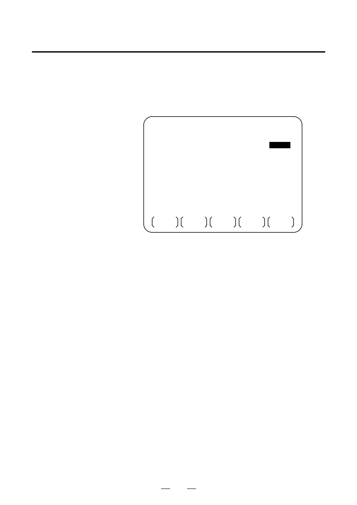
3. INPUT AND OUTPUT OF DATA
B-64115EN/02
To input/output a particular type of data, the corresponding screen is
3.3
usually selected. For example, the parameter screen is used for parameter
DATA INPUT/OUTPUT
input from or output to an external input/output unit, while the program
ON THE ALL IO
screen is used for program input or output. However, programs,
SCREEN
parameters, offset data, and macro variables can all be input and output
using a single common screen, that is, the ALL IO screen.
READ/PUNCH (PROGRAM)
O1234 N12345
I/O CHANNEL
1
TV CHECK
OFF
DEVICE NUM.
0
PUNCH CODE
ISO
BAUDRATE
4800
INPUT CODE
ASCII
STOP BIT
2
FEED OUTPUT
FEED
NULL INPUT (EIA)
NO
EOB OUTPUT (ISO) CR
TV CHECK (NOTES)
ON
(0:EIA
1:ISO)>1_
MDI
* * * *
* * *
* * *
* * *
12:34:56
PRGRM
PARAM
OFFSET
MACRO
(OPRT)
Fig. 3.3
ALL IO screen (when channel 1 is being
used for input/output)
260
3. INPUT AND OUTPUT OF DATA
B-64115EN/02
3.3.1
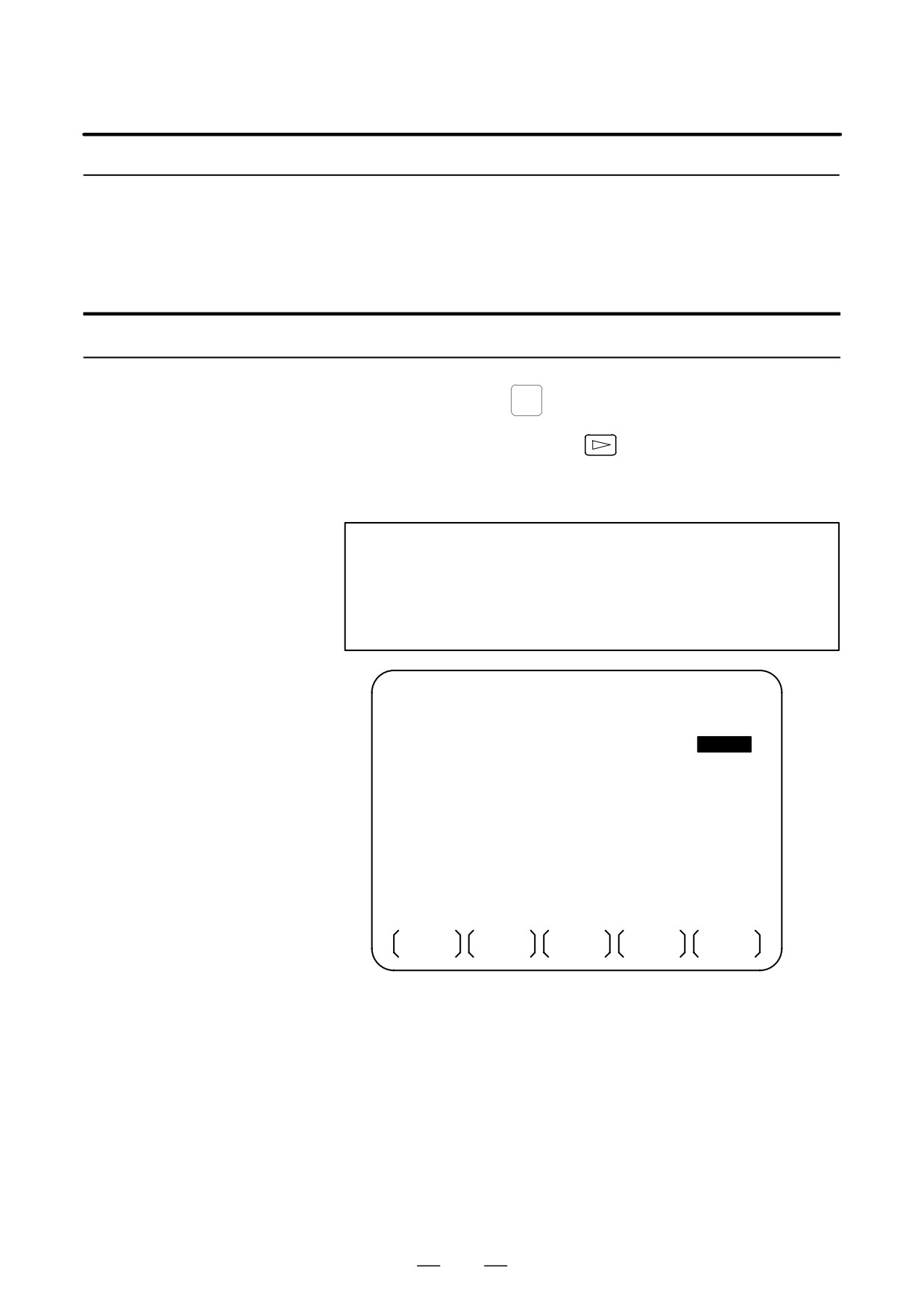
Input/output-related parameters can be set on the ALL IO screen.
Parameters can be set, regardless of the mode.
Setting
Input/Output-Related
Parameters
Setting input/output-related parameters
Procedure
1
Press function key
SYSTEM
2
Press the rightmost soft key
(continuous menu key) several
times.
3
Press soft key [ALL IO] to display the ALL IO screen.
NOTE
1
If program or floppy is selected in EDIT mode, the program
directory or floppy screen is displayed.
2
When the power is first turned on, program is selected by
default.
READ/PUNCH (PROGRAM)
O1234 N12345
I/O CHANNEL
1
TV CHECK
OFF
DEVICE NUM.
0
PUNCH CODE
ISO
BAUDRATE
4800
INPUT CODE
ASCII
STOP BIT
2
FEED OUTPUT
FEED
NULL INPUT (EIA)
NO
EOB OUTPUT (ISO) CR
TV CHECK (NOTES)
ON
(0:EIA
1:ISO)>1_
MDI
* * * *
* * *
* * *
* * *
12:34:56
PRGRM
PARAM
OFFSET
MACRO
(OPRT)
4
Select the soft key corresponding to the desired type of data (program,
parameter, and so forth).
5
Set the parameters corresponding to the type of input/output unit to be
used.
(Parameter setting is possible regardless of the mode.)
261
3. INPUT AND OUTPUT OF DATA
B-64115EN/02
Tip
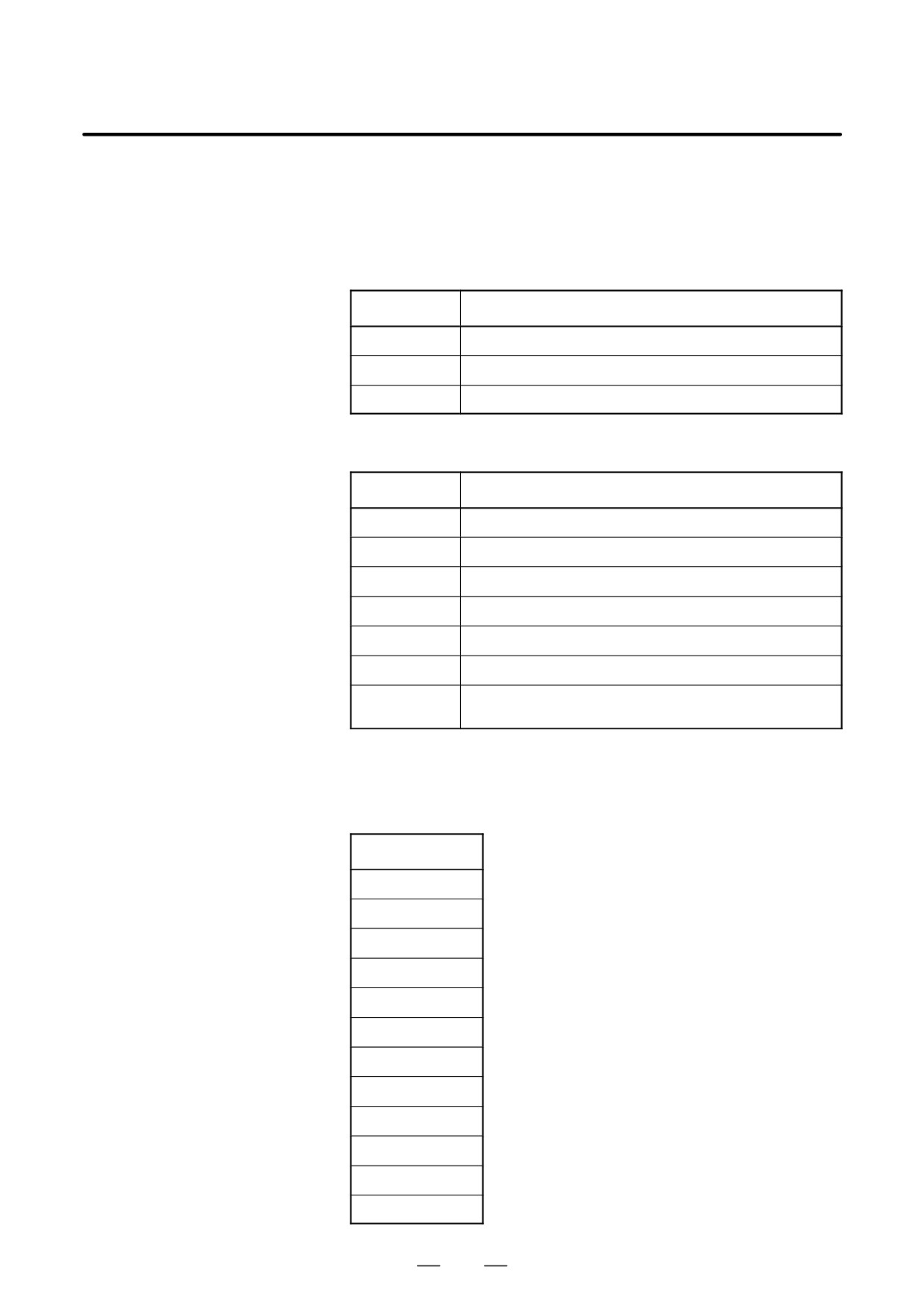
First, set an I/O channel. The parameters on this screen change to those
corresponding to a specified I/O channel.
D
I/O channel (0 to 2)
Setting
Corresponding parameter
0
No. 101 to 103
1
No. 111 to 113
2
No. 121 to 123
D
Device number
Setting
Input/output device
0
RS-232-C (The control codes DC1 through DC4 are used.)
1
FANUC CASSETTE ADAPTOR 1 (FANUC CASSETTE B1/B2)
2
FANUC CASSETTE ADAPTOR 3 (FANUC CASSETTE F1)
3
FANUC Handy File
4
RS-232-C (The control codes DC1 through DC4 are not used.)
5
Portable tape reader
6
FANUC PPR
FANUC SYSTEM P-MODEL G, FANUC SYSTEM P-MODEL H
D
Baud rate (bps)
Set a desired baud rate value indicated below.
Baud rate (bps)
50
100
110
150
200
300
600
1200
2400
4800
9600
19200
262
3. INPUT AND OUTPUT OF DATA
B-64115EN/02
3.3.2
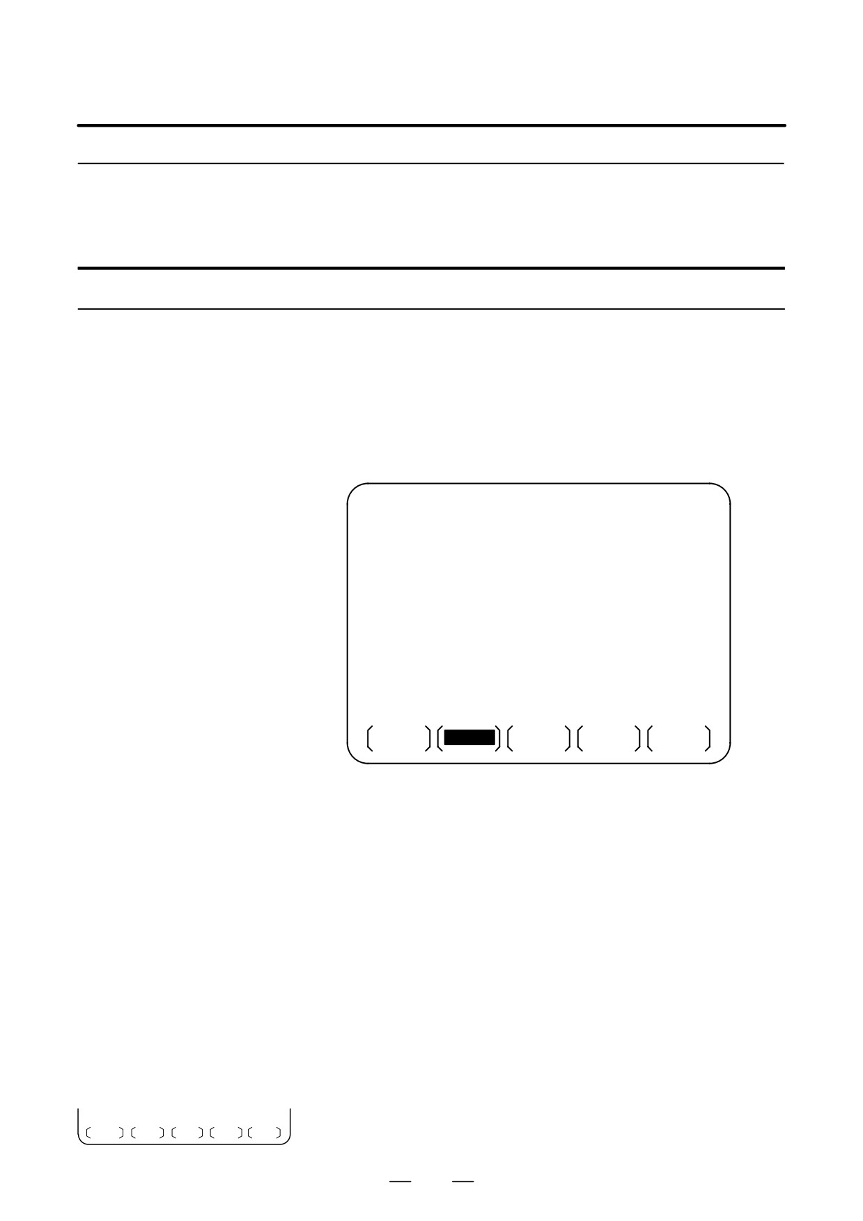
A program can be input and output using the ALL IO screen.
When entering a program using a cassette or card, the user must specify
Inputting and
the input file containing the program (file search).
Outputting Programs
File search
Procedure
1
Press soft key [PRGRM] on the ALL IO screen, described in Section
3.3.1.
2
Select EDIT mode. A program directory is displayed.
3
Press soft key [(OPRT)]. The screen and soft keys change as shown
below.
⋅
A program directory is displayed only in EDIT mode. In all other
modes, the ALL IO screen is displayed.
O0001 N00010
PROGRAM (NUM.)
MEMORY (CHAR.)
USED
:
60
3321
FREE
:
2
429
O0010 O0001 O0003 O0002 O0555 O0999
O0062 O0004 O0005 O1111 O0969 O6666
O0021 O1234 O0588 O0020 O0040
>_
EDIT
* * * *
* * *
* * *
* * *
14:46:09
F SRH
READ
PUNCH
DELETE
(OPRT)
4
Enter address N.
5
Enter the number of the file to be found.
⋅
N0
The first floppy file is found.
⋅
One of N1 to N9999
Among the files numbered from 1 to 9999, a specified file is found.
⋅
N-9999
The file immediately after that used most recently is found.
⋅
N-9998
When -9998 is specified, the next file is found. Then, each time
a file input/output operation is performed, N-9999 is automatically
inserted. This means that subsequent files can be sequentially
found automatically.
This state is canceled by specifying N0, N1 to N9999, or N-9999,
or upon a reset.
6
Press soft keys [F SRH] and [EXEC].
CAN EXEC
The specified file is found.
263
3. INPUT AND OUTPUT OF DATA
B-64115EN/02
Inputting a program
Procedure
1
Press soft key [PRGRM] on the ALL IO screen, described in Section
3.3.1.
2
Select EDIT mode. A program directory is displayed.
3
Press soft key [(OPRT)]. The screen and soft keys change as shown
below.
⋅
A program directory is displayed only in EDIT mode. In all other
modes, the ALL IO screen is displayed.
O0001 N00010
PROGRAM (NUM.)
MEMORY (CHAR.)
USED
:
60
3321
FREE
:
2
429
O0010 O0001 O0003 O0002 O0555 O0999
O0062 O0004 O0005 O1111 O0969 O6666
O0021 O1234 O0588 O0020 O0040
>_
EDIT
* * * *
* * *
* * *
* * *
14:46:09
F SRH
READ
PUNCH
DELETE
(OPRT)
4
To specify a program number to be assigned to an input program,
enter address O, followed by the desired program number.
If no program number is specified, the program number in the file or
on the NC tape is assigned as is.
5
Press soft key [READ], then [EXEC].
STOP CAN EXEC
The program is input with the program number specified in step 4
assigned.
To cancel input, press soft key [CAN].
To stop input prior to its completion, press soft key [STOP].
264
3. INPUT AND OUTPUT OF DATA
B-64115EN/02
Outputting programs
Procedure
1
Press soft key [PRGRM] on the ALL IO screen, described in Section
3.3.1.
2
Select EDIT mode. A program directory is displayed.
3
Press soft key [(OPRT)]. The screen and soft keys change as shown
below.
⋅
A program directory is displayed only in EDIT mode. In all other
modes, the ALL IO screen is displayed.
O0001 N00010
PROGRAM (NUM.)
MEMORY (CHAR.)
USED
:
60
3321
FREE
:
2
429
O0010 O0001 O0003 O0002 O0555 O0999
O0062 O0004 O0005 O1111 O0969 O6666
O0021 O1234 O0588 O0020 O0040
>_
EDIT
* * * *
* * *
* * *
* * *
14:46:09
F SRH
READ
PUNCH
DELETE
(OPRT)
4
Enter address O.
5
Enter a desired program number.
If -9999 is entered, all programs in memory are output.
To output a range of programs, enter O∆∆∆∆, OVVVV. The
programs numbered from ∆∆∆∆ to VVVV are output.
When bit 4 (SOR) of parameter No. 3107 for sorted display is set to 1
on the program library screen, programs are output in order, starting
from those having the smallest program numbers.
6
Press soft key [PUNCH], then [EXEC].
STOP CAN EXEC
The specified program or programs are output. If steps 4 and 5 are
omitted, the currently selected program is output.
To cancel output, press soft key [CAN].
To stop output prior to its completion, press soft key [STOP].
265
3. INPUT AND OUTPUT OF DATA
B-64115EN/02
Deleting files
Procedure
1
Press soft key [PRGRM] on the ALL IO screen, described in Section
3.3.1.
2
Select EDIT mode. A program directory is displayed.
3
Press soft key [(OPRT)]. The screen and soft keys change as shown
below.
⋅
A program directory is displayed only in EDIT mode. In all other
modes, the ALL IO screen is displayed.
O0001 N00010
PROGRAM (NUM.)
MEMORY (CHAR.)
USED
:
60
3321
FREE
:
2
429
O0010 O0001 O0003 O0002 O0555 O0999
O0062 O0004 O0005 O1111 O0969 O6666
O0021 O1234 O0588 O0020 O0040
>_
EDIT
* * * *
* * *
* * *
* * *
14:46:09
F SRH
READ
PUNCH
DELETE
(OPRT)
4
Press soft key [DELETE].
5
Enter a file number, from 1 to 9999, to indicate the file to be deleted.
6
Press soft key [EXEC].
CAN EXEC
The k-th file, specified in step 5, is deleted.
266
3. INPUT AND OUTPUT OF DATA
B-64115EN/02
3.3.3
Parameters can be input and output using the ALL IO screen.
Inputting and
Outputting Parameters
Inputting parameters
Procedure
1
Press soft key [PARAM] on the ALL IO screen, described in Section
3.3.1.
2
Select EDIT mode.
3
Press soft key [(OPRT)]. Soft keys change as shown below.
READ
PUNCH
4
Press soft key [READ], then [EXEC].
CAN EXEC
The parameters are read, and the “INPUT” indicator blinks at the
lower-right corner of the screen. Upon the completion of input, the
“INPUT” indicator is cleared from the screen.
To cancel input, press soft key [CAN].
Outputting parameters
Procedure
1
Press soft key [PARAM] on the ALL IO screen, described in Section
3.3.1.
2
Select EDIT mode.
3
Press soft key [(OPRT)]. Soft keys change as shown below.
READ
PUNCH
4
Press soft key [PUNCH], then [EXEC].
CAN EXEC
The parameters are output, and the “OUTPUT” indicator blinks at the
lower-right corner of the screen. Upon the completion of output, the
“OUTPUT” indicator is cleared from the screen.
To cancel output, press soft key [CAN].
267
3. INPUT AND OUTPUT OF DATA
B-64115EN/02
3.3.4
Offset data can be input and output using the ALL IO screen.
Inputting and
Outputting Offset Data
Inputting offset data
Procedure
1
Press soft key [OFFSET] on the ALL IO screen, described in Section
3.3.1.
2
Select EDIT mode.
3
Press soft key [(OPRT)]. Soft keys change as shown below.
READ
PUNCH
4
Press soft key [READ], then [EXEC].
CAN EXEC
The offset data is read, and the “INPUT” indicator blinks at the
lower-right corner of the screen.
Upon the completion of input, the “INPUT” indicator is cleared from
the screen.
To cancel input, press soft key [CAN].
Outputting offset data
Procedure
1
Press soft key [OFFSET] on the ALL IO screen, described in Section
3.3.1.
2
Select EDIT mode.
3
Press soft key [(OPRT)]. Soft keys change as shown below.
READ
PUNCH
4
Press soft key [PUNCH], then [EXEC].
CAN EXEC
The offset data is output, and the “OUTPUT” indicator blinks at the
lower-right corner of the screen. Upon the completion of output, the
“OUTPUT” indicator is cleared from the screen.
To cancel output, press soft key [CAN].
268
3. INPUT AND OUTPUT OF DATA
B-64115EN/02
3.3.5
Custom macro common variables can be output using the ALL IO screen.
Outputting Custom
Macro Common
Variables
Outputting custom macro common variables
Procedure
1
Press soft key [MACRO] on the ALL IO screen, described in Section
3.3.1.
2
Select EDIT mode.
3
Press soft key [(OPRT)]. Soft keys change as shown below.
READ
PUNCH
4
Press soft key [PUNCH], then [EXEC].
CAN EXEC
The custom macro common variables are output, and the “OUTPUT”
indicator blinks at the lower-right corner of the screen. Upon the
completion of output, the “OUTPUT” indicator is cleared from the
screen.
To cancel output, press soft key [CAN].
NOTE
To input a macro variable, read the desired custom macro
statement as a program, then execute the program.
269
3. INPUT AND OUTPUT OF DATA
B-64115EN/02
3.3.6
The ALL IO screen supports the display of a directory of floppy files, as
well as the input and output of floppy files.
Inputting and
Outputting Floppy
Files
Displaying a file directory
Procedure
1
Press the rightmost soft key
(continuous menu key) on the ALL
IO screen, described in Section 3.3.1.
2
Press soft key [FLOPPY].
3
Select EDIT mode. The floppy screen is displayed.
4
Press soft key [(OPRT)]. The screen and soft keys change as shown
below.
⋅
The floppy screen is displayed only in EDIT mode. In all other
modes, the ALL IO screen is displayed.
READ/PUNCH (FLOPPY)
O1234 N12345
>
MDI
* * * *
* * *
* * *
* * *
12:34:56
F SRH
READ
PUNCH
DELETE
5
Press soft key [F SRH].
6
Enter the number of the desired file, then press soft key [F SET].
F SET
CAN EXEC
7
Press soft key [EXEC]. A directory is displayed, with the specified
file uppermost. Subsequent files in the directory can be displayed by
pressing the page key.
270
3. INPUT AND OUTPUT OF DATA
B-64115EN/02
READ/PUNCH (FLOPPY)
O1234 N12345
No. FILE NAME
(Meter) VOL
0001
PARAMETER
46.1
0002
ALL.PROGRAM
12.3
0003
O0001
11.9
0004
O0002
11.9
0005
O0003
11.9
0006
O0004
11.9
0007
O0005
0008
O0010
11.9
0009
O0020
11.9
11.9
F SRH
File No.=2
>2_
EDIT
* * * *
* * *
* * *
* * *
12:34:56
F SRH
CAN
EXEC
A directory in which the first file is uppermost can be displayed
simply by pressing the page key.
(Soft key [F SRH] need not be
pressed.)
271
3. INPUT AND OUTPUT OF DATA
B-64115EN/02
Inputting a file
Procedure
1
Press the rightmost soft key
(continuous menu key) on the ALL
IO screen, described in Section 3.3.1.
2
Press soft key [FLOPPY].
3
Select EDIT mode. The floppy screen is displayed.
4
Press soft key [(OPRT)]. The screen and soft keys change as shown
below.
The floppy screen is displayed only in EDIT mode. In all other
modes, the ALL IO screen is displayed.
READ/PUNCH (FLOPPY)
O1234 N12345
>
MDI
* * * *
* * *
* * *
* * *
12:34:56
F SRH
READ
PUNCH
DELETE
5
Press soft key [READ].
6
Enter the number of a file or program to be input.
F SET O SET STOP CAN EXEC
⋅
Setting a file number: Enter the number of the desired file, then
press soft key [F SET].
⋅
Setting a program number: Enter the number of the desired
program, then press soft key [O SET].
7
Press soft key [EXEC].
The specified file or program is read, and the “INPUT” indicator
blinks at the lower-right corner of the screen. Upon the completion of
input, the “INPUT” indicator is cleared from the screen.
272
3. INPUT AND OUTPUT OF DATA
B-64115EN/02
Outputting a file
Procedure
1
Press the rightmost soft key
(continuous menu key) on the ALL
IO screen, described in Section 3.3.1.
2
Press soft key [FLOPPY].
3
Select EDIT mode. The floppy screen is displayed.
4
Press soft key [(OPRT)]. The screen and soft keys change as shown
below.
The floppy screen is displayed only in EDIT mode. In all other
modes, the ALL IO screen is displayed.
READ/PUNCH (FLOPPY)
O1234 N12345
>
MDI
* * * *
* * *
* * *
* * *
12:34:56
F SRH
READ
PUNCH
DELETE
5
Press soft key [PUNCH].
6
Enter the number of the program to be output, together with a desired
F SET O SET STOP CAN EXEC
output file number.
⋅
Setting a file number: Enter the number of the desired file, then
press soft key [F SET].
⋅
Setting a program number: Enter the number of the desired
program, then press soft key [O SET].
7
Press soft key [EXEC].
The specified program is output, and the “OUTPUT” indicator blinks
at the lower-right corner of the screen. Upon the completion of
output, the “OUTPUT” indicator is cleared from the screen.
If no file number is specified, the program is written at the end of the
currently registered files.
273
3. INPUT AND OUTPUT OF DATA
B-64115EN/02
Deleting a file
Procedure
1
Press the rightmost soft key
(continuous menu key) on the ALL
IO screen, described in Section 3.3.1.
2
Press soft key [FLOPPY].
3
Select EDIT mode. The floppy screen is displayed.
4
Press soft key [(OPRT)]. The screen and soft keys change as shown
below.
The floppy screen is displayed only in EDIT mode. In all other
modes, the ALL IO screen is displayed.
READ/PUNCH (FLOPPY)
O1234 N12345
>
MDI
* * * *
* * *
* * *
* * *
12:34:56
F SRH
READ
PUNCH
DELETE
5
Press soft key [DELETE].
6
Enter the number of the desired file, then press soft key [F SET].
F SET
CAN EXEC
7
Press soft key [EXEC]. The specified file is deleted. After the file has
been deleted, the subsequent files are shifted up.
274
3. INPUT AND OUTPUT OF DATA
B-64115EN/02
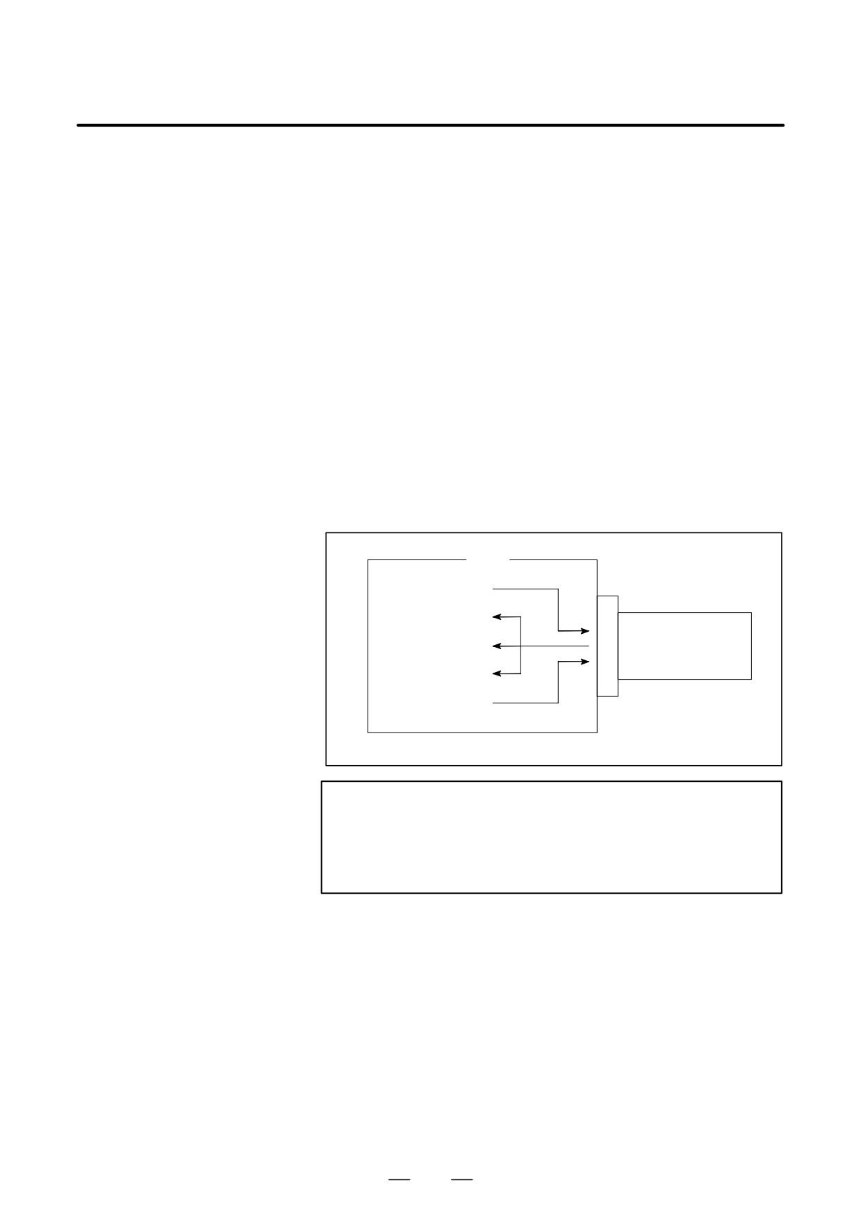
If the I/O channel (parameter No. 20) is set to 4, files on the memory card
3.4
can be referenced and various types of data such as part programs,
DATA INPUT/OUTPUT
parameters, and offset data can be input and output in text file format by
USING A MEMORY
using the memory card interface of the control unit.
CARD
The major functions are listed below.
⋅
Displaying a directory of stored files
The files stored on a memory card can be displayed on the directory
screen.
⋅
Searching for a file
A search is made for a file on a memory card and, if found, it is
displayed on the directory screen.
⋅
Reading a file
Text-format files can be read from a memory card.
⋅
Writing a file
Data such as part programs can be stored to a memory card in text file
format.
⋅
Deleting a file
A file can be selected and deleted from a memory card.
CNC
Writing a file
Reading a file
Displaying a directory
Memory card
Searching for a file
Deleting a file
NOTE
When using the program stored on a memory card to make
a subprogram call for RMT mode operation (DNC operation)
or the M198 command, use the special retainer for securing
a memory card to the CNC.
If an attempt is made to write parameters or NC programs to an existing
file on the memory card, the OWM parameter (bit 6 of parameter No.
0138) can be used to specify whether to display an overwriting
confirmation message. If OWM = 1, overwriting is done with no
confirmation message displayed.
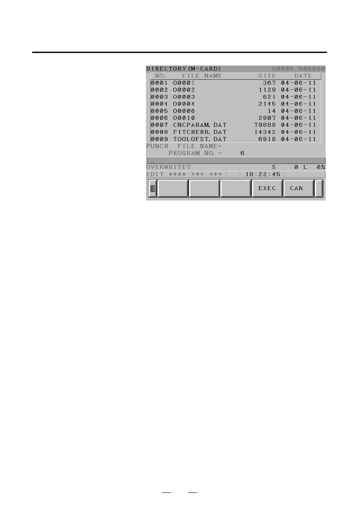
When you press the [EXEC] soft key after the [PUNCH] soft key, the
confirmation message shown below appears on the lower left corner of the
screen, if the memory card already contains a file by the same name as
specified.
275
3. INPUT AND OUTPUT OF DATA
B-64115EN/02
⋅
To overwrite, press the [EXEC] soft key again.
⋅
To avoid overwriting, press the [CANCEL] soft key, the “<” soft key
on the left, or the reset button. It is impossible to go to any other screen
if this message is displayed.
⋅
No confirmation message is displayed for any output file name
selected from the screen hard copy function, the maintenance
information screen, or the PMC screen.
276
3. INPUT AND OUTPUT OF DATA
B-64115EN/02
Displaying a directory of stored files
Procedure
1
Press the EDIT switch on the machine operator’s panel.
2
Press function key
PROG
3
Press the rightmost soft key
(continuous menu key).
4
Press soft key [CARD]. The screen shown below is displayed. Using
page keys
and
, the screen can be scrolled.
DIRECTORY (M-CARD)
O0034 N00045
No. FILE NAME
SIZE
DATE
0001
O1000
123456
01/07/10
0002
O1001
118458
01/07/30
0003
O0002
113250
01/07/30
0004
O2000
173456
01/07/31
0005
O2001
113444
01/07/31
0006
O3001
118483
01/08/02
0007
O3300
111406
01/08/05
0008
O3400
112420
01/07/31
0009
O3500
117460
01/07/31
~
~
PROG
DIR +
(OPRT)
5
Comments relating to each file can be displayed by pressing soft key
[DIR+].
DIRECTORY (M-CARD)
O0034 N00045
No. FILE NAME
COMMENT
0001
O1000
(COMMENT
)
0002
O1001
(SUB PROGRAM )
0003
O0002
(12345678
)
0004
O2000
(
)
0005
O2001
(
)
0006
O3001
(SKIP-K
)
0007
O3300
(HI-SPEED
)
0008
O3400
(
)
0009
O3500
(TEST PROGRAM)
~
~
PROG
DIR +
(OPRT)
6
Repeatedly pressing soft key [DIR+] toggles the screen between the
display of comments and the display of sizes and dates.
Any comment described after the O number in the file is displayed.
Up to 18 characters can be displayed on the screen.
277
3. INPUT AND OUTPUT OF DATA
B-64115EN/02
Searching for a file
Procedure
1
Press the EDIT switch on the machine operator’s panel.
2
Press function key
PROG
3
Press the rightmost soft key
(continuous menu key).
4
Press soft key [CARD]. The screen shown below is displayed.
DIRECTORY (M-CARD)
O0034 N00045
No. FILE NAME
SIZE
DATE
0001
O1000
123456
01/07/10
0002
O1001
118458
01/07/30
0003
O0002
113250
01/07/30
0004
O2000
173456
01/07/31
0005
O2001
113444
01/07/31
0006
O3001
118483
01/08/02
0007
O3300
111406
01/08/05
0008
O3400
112420
01/07/31
0009
O3500
117460
01/07/31
~
~
PROG
DIR +
(OPRT)
5
Press soft key [(OPRT)].
6
Set the number of the desired file number with soft key [F SRH].
F SRH F READ N READ PUNCH DELETE
Then, start the search by pressing soft key [EXEC]. If found, the file is
displayed at the top of the directory screen.
When a search is made for file number 19
DIRECTORY (M-CARD)
O0034 N00045
No. FILE NAME
COMMENT
0019
O1000
(MAIN PROGRAM)
0020
O1010
(SUBPROGRAM-1)
0021
O1020
(COMMENT
)
0022
O1030
(COMMENT
)
~
~
278
3. INPUT AND OUTPUT OF DATA
B-64115EN/02
Reading a file
Procedure
1
Press the EDIT switch on the machine operator’s panel.
2
Press function key
PROG
3
Press the rightmost soft key
(continuous menu key).
4
Press soft key [CARD]. Then, the screen shown below is displayed.
DIRECTORY (M-CARD)
O0034 N00045
No. FILE NAME
SIZE
DATE
0001
O1000
123456
01/07/10
0002
O1001
118458
01/07/30
0003
O0002
113250
01/07/30
0004
O2000
173456
01/07/31
0005
O2001
113444
01/07/31
0006
O3001
118483
01/08/02
0007
O3300
111406
01/08/05
0008
O3400
112420
01/07/31
0009
O3500
117460
01/07/31
~
~
PROG
DIR +
(OPRT)
5
Press soft key [(OPRT)].
F SRH F READ N READ PUNCH DELETE
6
To specify a file number, press soft key [F READ]. The screen shown
below is displayed.
DIRECTORY (M-CARD)
O0001 N00010
No. FILE NAME
COMMENT
0019
O1000
(MAIN PROGRAM)
0020
O1010
(SUBPROGRAM-1)
0021
O1030
(COMMENT
)
~
~
READ
FILE NAME=20
PROGRAM No.=120
>
EDIT
15:40:21
* * *
* * * *
* * *
* * * *
F NAME
O SET
STOP
CAN
EXEC
7
Enter file number 20 from the MDI panel, then set the file number by
pressing soft key [F SET]. Next, enter program number 120, then set
the program number by pressing soft key [O SET]. Then, press soft
key [EXEC].
⋅
File number 20 is registered as O0120 in the CNC.
⋅
Set a program number to register a read file with a separate O
number. If no program number is set, the O number in the file name
column is registered.
279