FANUC Series 0i-MODEL C, Series 0i Mate-MODEL C. MAINTENANCE MANUAL - page 11
3. INPUT AND OUTPUT OF DATA
B-64115EN/02
8
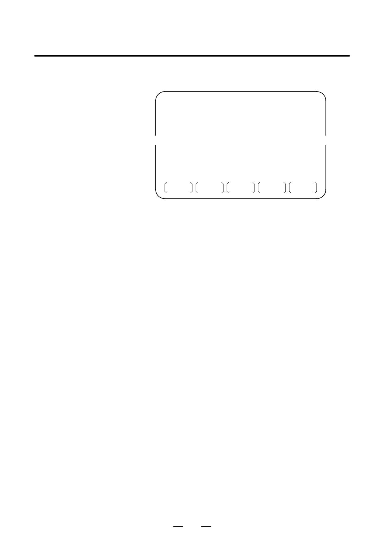
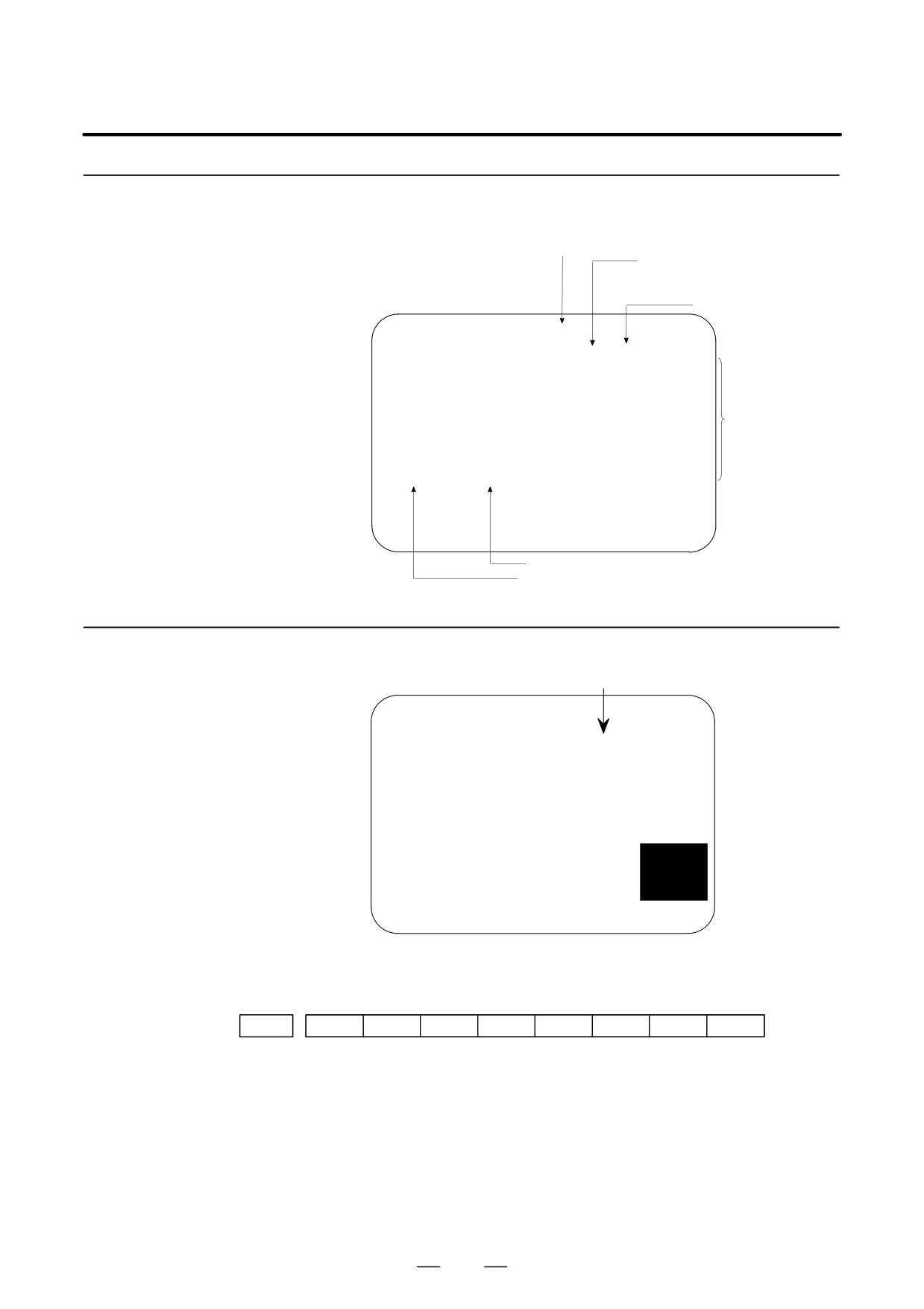
To specify a file with its file name, press soft key [N READ] in step 6
above. The screen shown below is displayed.
DIRECTORY (M-CARD)
O0001 N00010
No. FILE NAME
COMMENT
0012
O0050
(MAIN PROGRAM)
0013
TESTPRO
(SUB PROGRAM-1)
0014
O0060
(MACRO PROGRAM)
~
~
READ
FILE NAME
=TESTPRO
PROGRAM No. =1230
>
EDIT
15:40:21
* * *
* * * *
* * *
* * * *
F NAME
O SET
STOP
CAN
EXEC
9
To register file name TESTPRO as O1230, enter file name TESTPRO
from the MDI panel, then set the file name with soft key [F NAME].
Next, enter program number 1230, then set the program number with
soft key [O SET]. Then, press soft key [EXEC].
280
3. INPUT AND OUTPUT OF DATA
B-64115EN/02
Writing a file
Procedure
1
Press the EDIT switch on the machine operator’s panel.
2
Press function key
PROG
3
Press the rightmost soft key
(continuous menu key).
4
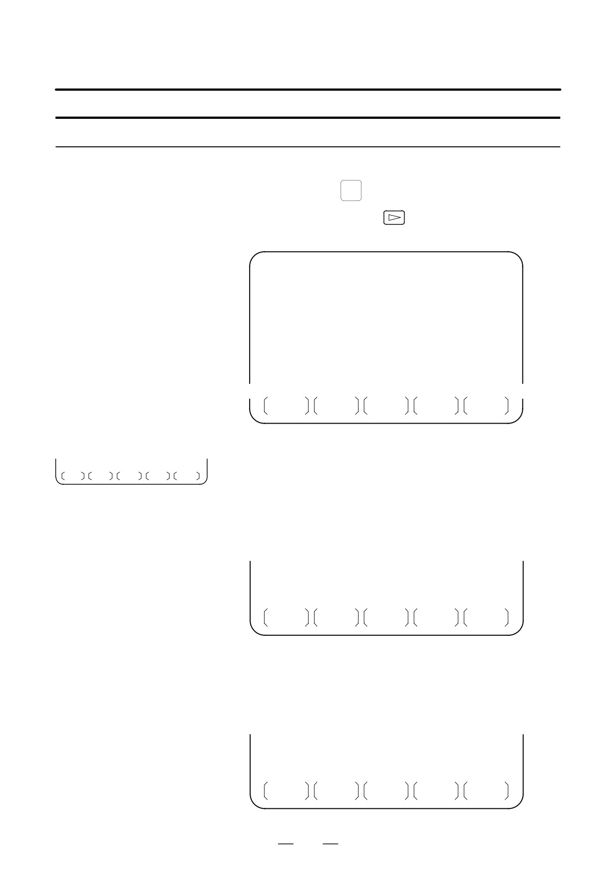
Press soft key [CARD]. The screen shown below is displayed.
DIRECTORY (M-CARD)
O0034 N00045
No. FILE NAME
SIZE
DATE
0001
O1000
123456
01/07/10
0002
O1001
118458
01/07/30
0003
O0002
113250
01/07/30
0004
O2000
173456
01/07/31
0005
O2001
113444
01/07/31
0006
O3001
118483
01/08/02
0007
O3300
111406
01/08/05
0008
O3400
112420
01/07/31
0009
O3500
117460
01/07/31
~
~
PROG
DIR +
(OPRT)
5
Press soft key [(OPRT)].
6
Press soft key [PUNCH].
F SRH
F READ
N READ
PUNCH
DELETE
7
Enter a desired O number from the MDI panel, then set the program
number with soft key [O SET].
When soft key [EXEC] is pressed after the setting shown below has
been made, for example, the file is written under program number
O1230.
~
~
PUNCH
FILE NAME
=
PROGRAM No. =1230
>
EDIT
15:40:21
* * *
* * * *
* * *
* * * *
F NAME
O SET
STOP
CAN
EXEC
8
In the same way as for O number setting, enter a desired file name
from the MDI panel, then set the file name with soft key [F SET].
When soft key [EXEC] is pressed after the setting shown below has
been made, for example, the file is written under program number
O1230 and file name ABCD12.
~
~
PUNCH
FILE NAME
=ABCD12
PROGRAM No. =1230
>
EDIT
* * *
* * * *
* * *
* * * *
15:40:21
F NAME
O SET
STOP
CAN
EXEC
281
3. INPUT AND OUTPUT OF DATA
B-64115EN/02
Deleting a file
Procedure
1
Press the EDIT switch on the machine operator’s panel.
2
Press function key
PROG
3
Press the rightmost soft key
(continuous menu key).
4
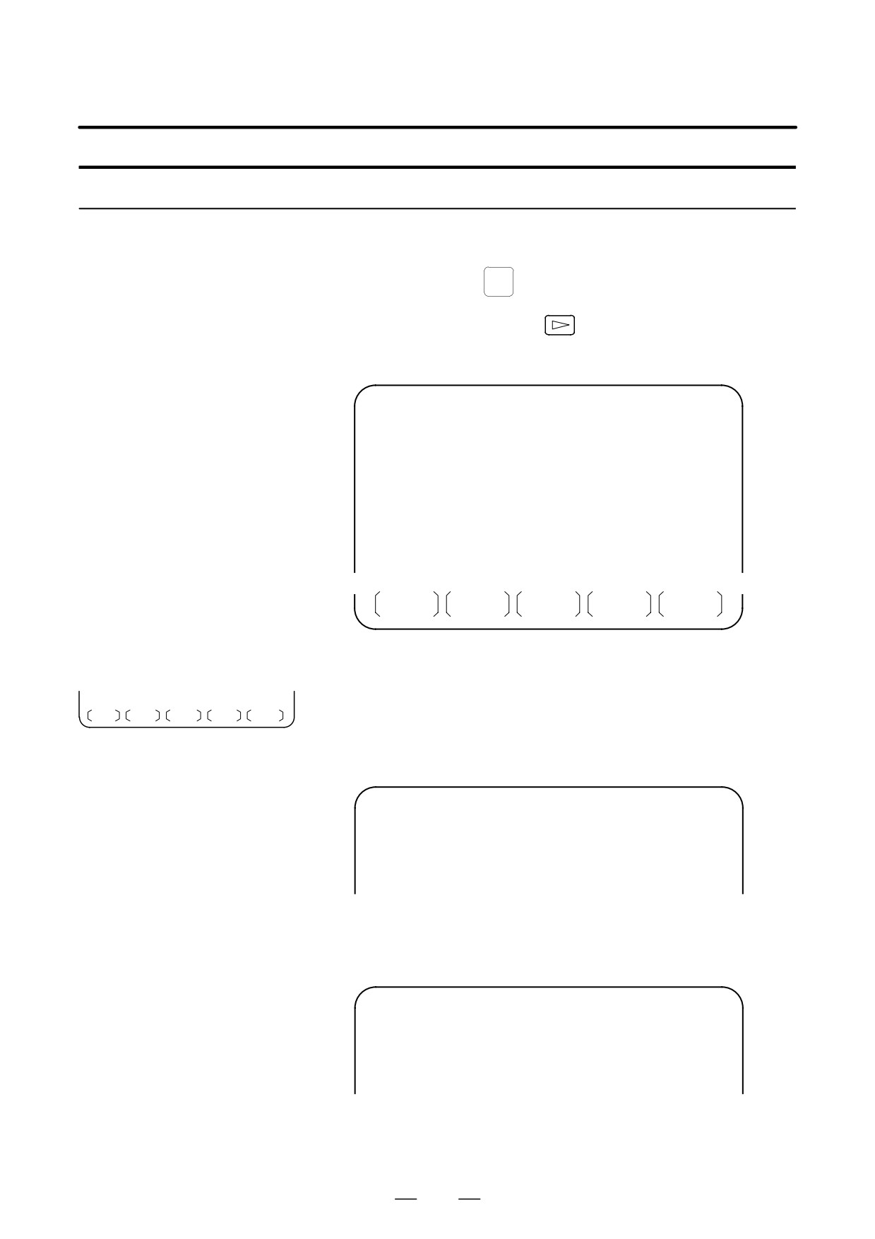
Press soft key [CARD]. The screen shown below is displayed.
DIRECTORY (M-CARD)
O0034 N00045
No. FILE NAME
SIZE
DATE
0001
O1000
123456
01/07/10
0002
O1001
118458
01/07/30
0003
O0002
113250
01/07/30
0004
O2000
173456
01/07/31
0005
O2001
113444
01/07/31
0006
O3001
118483
01/08/02
0007
O3300
111406
01/08/05
0008
O3400
112420
01/07/31
0009
O3500
117460
01/07/31
~
~
PROG
DIR +
(OPRT)
5
Press soft key [(OPRT)].
6
Set the number of the desired file with soft key [DELETE], then press
F SRH F READ N READ PUNCH DELETE
soft key [EXEC]. The file is deleted, and the directory screen is
displayed again.
When file number 21 is deleted
DIRECTORY (M-CARD)
O0034 N00045
No. FILE NAME
COMMENT
0019
O1000
(MAIN PROGRAM)
0020
O1010
(SUBPROGRAM-1)
0021
O1020
(COMMENT
)
0022
O1030
(COMMENT
)
~
~
File name O1020 is deleted.
DIRECTORY (M-CARD)
O0034 N00045
No. FILE NAME
COMMENT
0019
O1000
(MAIN PROGRAM)
0020
O1010
(SUBPROGRAM-1)
0021
O1020
(COMMENT
)
0022
O1030
(COMMENT
)
~
~
File number 21 is assigned to the next file name.
282
3. INPUT AND OUTPUT OF DATA
B-64115EN/02
Batch input/output with a memory card
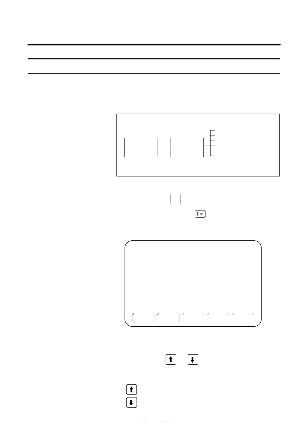
On the ALL IO screen, different types of data including part programs,
parameters, offset data, pitch error data, custom macros, and workpiece
coordinate system data can be input and output using a memory card; the
screen for each type of data need not be displayed for input/output.
Data item name
Part program
Parameter
Offset data
Memory card
²
ALL IO screen
Pitch error data
³
Custom macro
Workpiece coordinate system
data
(additional coordinate systems)
Procedure
1
Press the EDIT switch on the machine operator’s panel.
2
Press function key
SYSTEM
3
Press the rightmost soft key
(continuous menu key) several
times.
4
Press soft key [ALL IO]. The screen shown below is displayed.
READ/PUNCH (PROGRAM)
O0001 N00001
No. FILE NAME
SIZE
DATE
* 0001
O0222
332010
01-04-06
0002
O1003
334450
01-05-04
0003
MACROVAR.DAT 653400
01-05-12
0004
O0002
341205
01-05-13
[PROGRAM]
O0001
O0002
O0003
O0005
O0100
O0020
O0006
O0004
O0110
O0200
O2200
O0441
O0330
>
EDIT
10:07:37
* * *
* * * *
* * *
* * * *
PROG
PARAM
OFFSET
(OPRT)
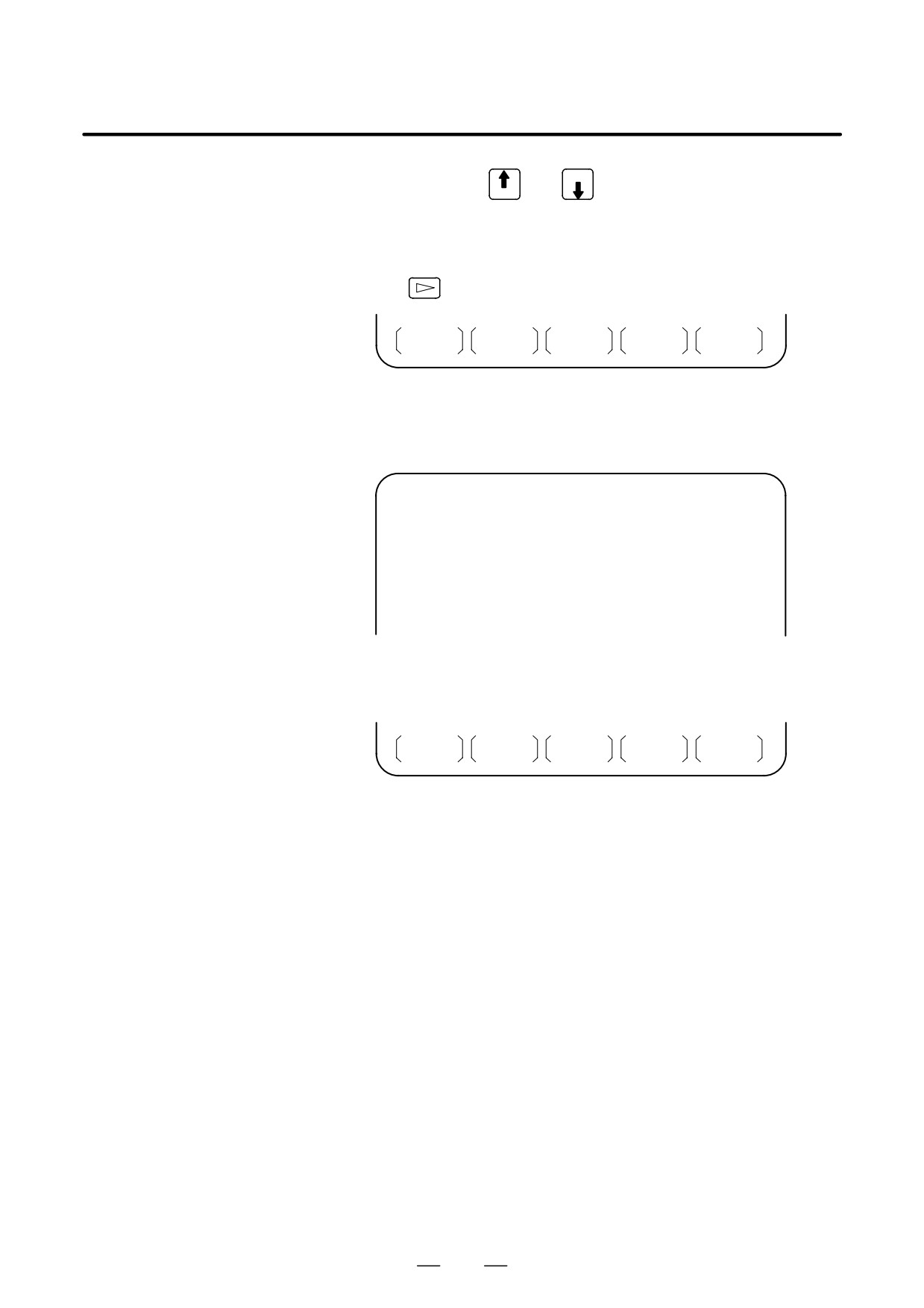
Upper part : Directory of files on the memory card
Lower part : Directory of registered programs
5
With cursor keys
and
, the user can choose between upper
part scrolling and lower part scrolling. (An asterisk (*) displayed at
the left edge indicates the part for which scrolling is possible.)
: Used for memory card file directory scrolling.
: Used for program directory scrolling.
283
3. INPUT AND OUTPUT OF DATA
B-64115EN/02
PAGE
6
With page keys
and
, scroll through the file directory or
PAGE
program directory.
7
When this screen is displayed, the program data item is selected. The
soft keys for other screens are displayed by pressing the rightmost soft
key
(continuous menu key).
PITCH
WORK
(OPRT)
When a data item other than program is selected, the screen displays only
a file directory.
A data item is indicated, in parentheses, on the title line.
READ/PUNCH (PARAMETER)
O0001 N00001
No. FILE NAME
SIZE
DATE
0001
O0222
332010
96/04/06
0002
O1003
334450
96/05/04
0003
MACROVAR.DAT
653400
96/05/12
0004
O0003
334610
96/05/04
0005
O0001
334254
96/06/04
0006
O0002
333750
96/06/04
0007
CNCPARAM.DAT
334453
96/06/04
~
~
8
Display the following soft keys with soft key [(OPRT)].
F SRH
F READ
N READ
PUNCH
DELETE
The operation of each function is the same as on the directory (memory
card) screen. Soft key [O SET], used for program number setting, and the
“PROGRAM NUMBER =” indication are not displayed for data items
other than program.
[F SRH]
: Finds a specified file number.
[F READ] : Reads a specified file number.
[PUNCH]
: Writes a file.
[N READ] : Reads a file under a specified file name.
[DELETE] : Deletes a specified file number.
284

3. INPUT AND OUTPUT OF DATA
B-64115EN/02
Error codes
Memory card error codes
Code
Meaning
007
The memory card is protected.
030
The memory card is not inserted into its slot.
032
The memory card’s battery is exhausted.
102
The memory card does not have sufficient free space.
105
No memory card is mounted.
106
A memory card is already mounted.
110
The specified directory cannot be found.
111
There are too many files under the root directory to allow a di-
rectory to be added.
114
The specified file cannot be found.
115
The specified file is protected.
117
The file has not yet been opened.
118
The file is already open.
119
The file is locked.
121
A file end was detected.
122
The specified file name is invalid.
124
The extension of the specified file is invalid.
129
A non-corresponding function was specified.
130
The specification of a device is invalid.
131
The specification of a pathname is invalid.
133
Multiple files are open at the same time.
135
The device is not formatted.
140
The file has the read/write disabled attribute.
285
4. INTERFACE BETWEEN CNC AND PMC
B-64115EN/02
INTERFACE BETWEEN CNC AND PMC
4
This chapter describes the signals between the machine operator’s panel,
magnetics cabinet and the PMC, connection of the signals between PMC
and CNC, and confirmation method of on/off state of these signals.
It also describes system configuration of PMC, parameters of PMC,
ladder and how to display time chart of the signals on the screen.
It also describes a method of inputting/outputting PMC parameters to an
external device.
4.1
GENERAL OF INTERFACE
287
4.2
SPECIFICATION OF PMC
288
4.3
PMC SCREEN (PMC-SA1)
298
4.4
PMC SCREEN (PMC-SB7)
321
4.5
LIST OF SIGNALS BY EACH MODE
354
4.6
LIST OF INPUT/OUTPUT SIGNALS
356
4.7
LIST OF ADDRESSES
371
286

High-speed processing signal
PMCDGN Input
Contacts
*DEC
a *ESP, SKIP, ESKIP, XAE, YAE, ZAE (M series)
[0]
0V
Open
*DEC
a *ESP, SKIP, ESKIP, XAE, ZAE, +MIT a (T series)
[1]
. . 24V
Close
NC
PMCDGN
PMCDGN * DI/DO
PMC-SA/SB
MT (Machine Tool builder)
ST1 DOOR
ST
ST1
G
X
RV
X0.1
X0.0
G007.2
ST2
ST2
0V
+24E
X5.7
Power
STL
STL
supply
F0.5
Y0.1
Load
+
F
Y
-
PMCDGN
PMCDGN *
0V
0V
PMCDGN
Tr Output
Load
[0]
Off
24V
Off
FANUC decides
PMC address
MTB decides
addresses
addresses
[1]
On
0V
On
and signals
Internal relay
and signals
correspondence
Variable timer
Counter
Data table
Message display
Keep relay
System reserve
area

4. INTERFACE BETWEEN CNC AND PMC
B-64115EN/02
4.2
SPECIFICATION OF
PMC
4.2.1
Specification
Series 0i-C/0i Mate-C
Series 0i-C
Function
PMC-SA1
PMC-SB7
Programming method
Ladder
Ladder
Number of ladder levels
2
3
1st level execution period
8ms
8ms
Basic instruction execution time
5.0m sec/step
0.033m sec/step
Program size
D Ladder
5,000 steps max.
Approx. 24,000 steps max.(NOTE 1, 2)
D Symbol/comment
1 to 128 KB
1 KB and up (NOTE 2)
D Message
0.1 to 64 KB
8 KB and up (NOTE 2)
Instruction (basic)
12
14
(functional)
48
69
Intemal relay
(R)
1,100 bytes
8,500 bytes
Extended relay
(E)
-
8,000 bytes
Message request
(A)
200 requests (25 bytes)
2,000 requests (500 bytes, 2 bits/request)
Nonvolatile memory and so on
D Data table
(D)
1,860 bytes
10,000 bytes
D Variable timer
(T)
40 units (80 bytes)
250 units (1,000 bytes, 4 bytes/unit)
Fixed timer
100 units
500 units (timer number specification)
D Counter
(C)
20 units (80 bytes)
100 units (400 bytes, 4 bytes/unit)
Fixed counter
(C)
-
100 units (200 bytes, 2 bytes/unit)
D Keep relay
(K)
20 bytes
120 bytes
Subprogram
(P)
-
2,000 programs
Label
(L)
-
9,999 units
Input/output (I/O Link)
D Input
240 points max.
1,024 points max.
D Output
160 points max.
1,024 points max.
Sequence program storage memory
Flash ROM
Flash ROM
128KB
128 KB
256 KB
NOTE
1
The maximum number of steps assumes programming using basic instructions. The maximum
number of steps varies according to the status of functional instruction use.
2
The total sequence program size (including all of the ladders, symbols/comments, and
messages) must not exceed the capacity of the sequence program storage memory. If the size
of any of the ladders, symbols/comments, or messages is greater, the maximum allowable size
of the others may be limited.
288

B-64115EN/02
4. INTERFACE BETWEEN CNC AND PMC
4.2.2
Address
Model
Char-
Signal type
Series 0i-C/0i Mate-C
acter
PMC-SA1
PMC-SB7
X
Input signal from the machine to the PMC
X0 to X127
X0 to X127
(MT to PMC)
X200 to X327(NOTE 1)
X1000 to X1127(NOTE 1)
Y
Output signal from the PMC to the machine
Y0 to Y127
Y0 to Y127
(PMC to MT)
Y200 to Y327(NOTE 1)
Y1000 to Y1127 (NOTE 1)
F
Input signal from the NC to the PMC
F0 to F255
F0 to F767(NOTE 2)
(NC to PMC)
F1000 to F1767(NOTE 3)
F2000 to F2767(NOTE 3)
F3000 to F3767(NOTE 3)
G
Output signal from the PMC to the NC (PMC to NC)
G0 to G255
G0 to G767(NOTE 2)
G1000 to G1767(NOTE 3)
G2000 to G2767(NOTE 3)
G3000 to G3767(NOTE 3)
R
Internal relay
R0 to R999
R0 to R7999
R9000 to R9099
R9000 to R9499(NOTE 4)
E
Extended relay
-
E0 to E7999(NOTE 5)
A
Message display request signal
A0 to A24
A0 to A249
Message display state signal
-
A9000 to A9249(NOTE 6)
C
Counter
C0 to C79
C0 to C399
C5000 to C5199(NOTE 7)
K
Keep relay
K0 to K19
K0 to K99
K900 to K919(NOTE 8)
T
Variable timer
T0 to T79
T0 to T499
T9000 to T9499(NOTE 9)
D
Data table
D0 to D1859
D0 to D9999
L
Label number
-
L1 to L9999
P
Subprogramnumber
-
P1 to P2000
289
4. INTERFACE BETWEEN CNC AND PMC
B-64115EN/02
NOTE
1
This area is reserved for the PMC. I/O cannot be assigned to this area. Do not use this area
for sequence programs.
2
This area includes an area reserved for the PMC. The actually usable address range depends
on the CNC system configuration.
3
This area is reserved for the PMC. Do not use this area for sequence programs.
4
This area is a special relay area managed by the PMC system program. When using this area,
follow the description of each signal.
5
In an ordinary system, this area can be used as with the internal relay (R) area. The extended
relay (E) area is volatile, but a signal is input to or output from a memory card as a PMC
parameter. When a PMC parameter is read, the E area is initialized to the state present at the
time of PMC parameter output.
6
Message display state signals corresponding to message display request signals on a
one-to-one basis. This area cannot be written to.
7
This area is used for the fixed counter instruction (CTRB instruction), which specifies a preset
value as a constant.
8
This area is a special relay area for PMC management software. When using this area, follow
the description of each address.
9
This area is reserved for the PMC. Do not use this area for sequence programs.
4.2.3
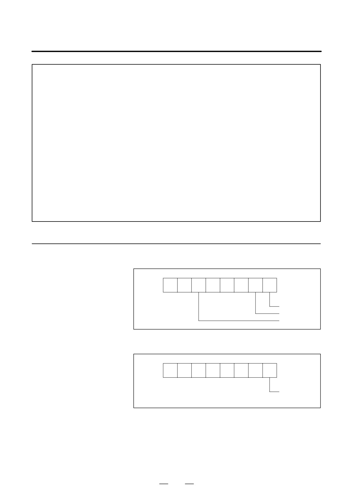
(1) R9000 (Operation output register for the ADD, SUB, MULB, DIVB,
and COMPB functional instructions)
System Reserve Area
of Internal Relay
#7
#6
#5
#4
#3
#2
#1
#0
R9000
V
N
Z
Operation result
register
Zero
Sign is minus
Overflow
(2) R9000 (Error output for the EXIN, WINDR, WINDW, MMCWR, and
MMCWW functional instructions)
#7
#6
#5
#4
#3
#2
#1
#0
R9000
The instruc-
tion ended in
error.
290
B-64115EN/02
4. INTERFACE BETWEEN CNC AND PMC
(3) R9002 to R9005 (Operation output registers for the DIVB functional
instruction)
The data remaining after the DIVB functional instruction is executed
in output.
#7
#6
#5
#4
#3
#2
#1
#0
R9002
R9003
Register for
remainder
R9004
(used by DIVB
instruction)
R9005
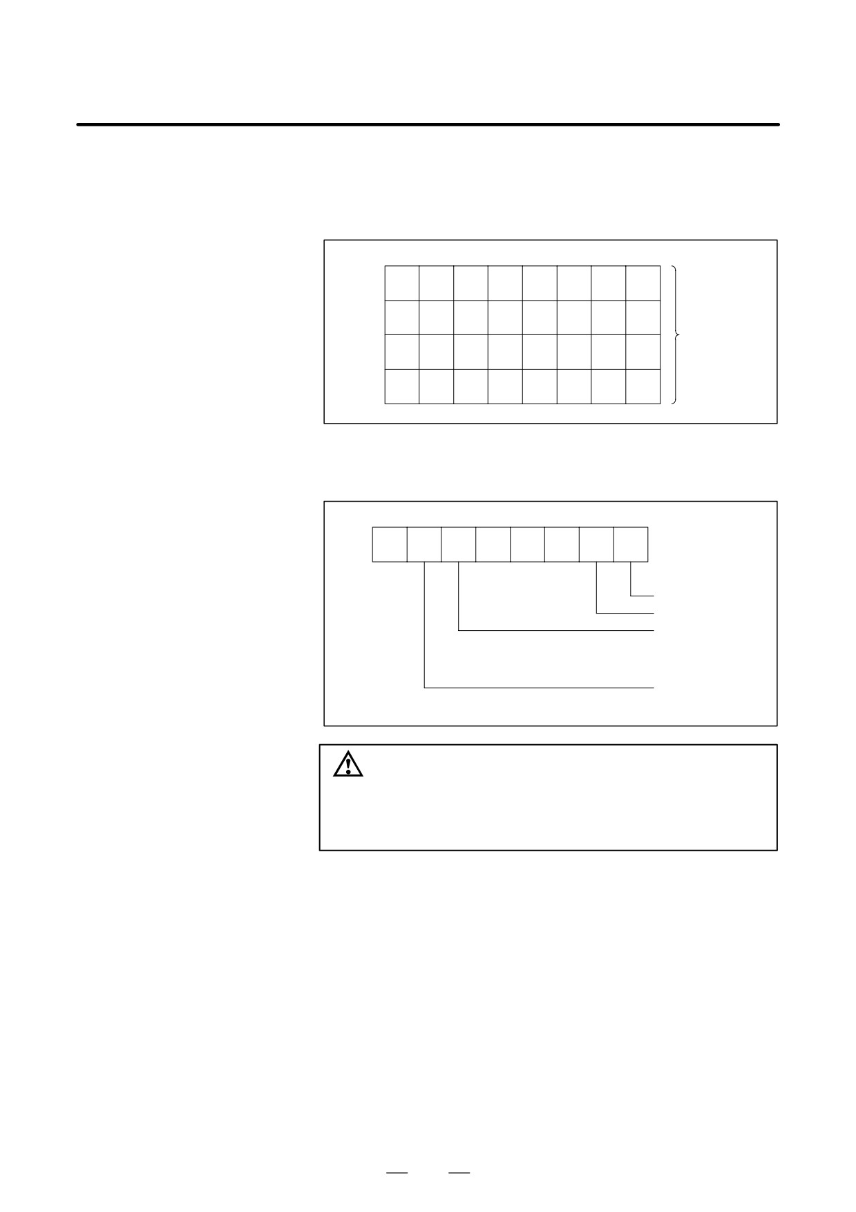
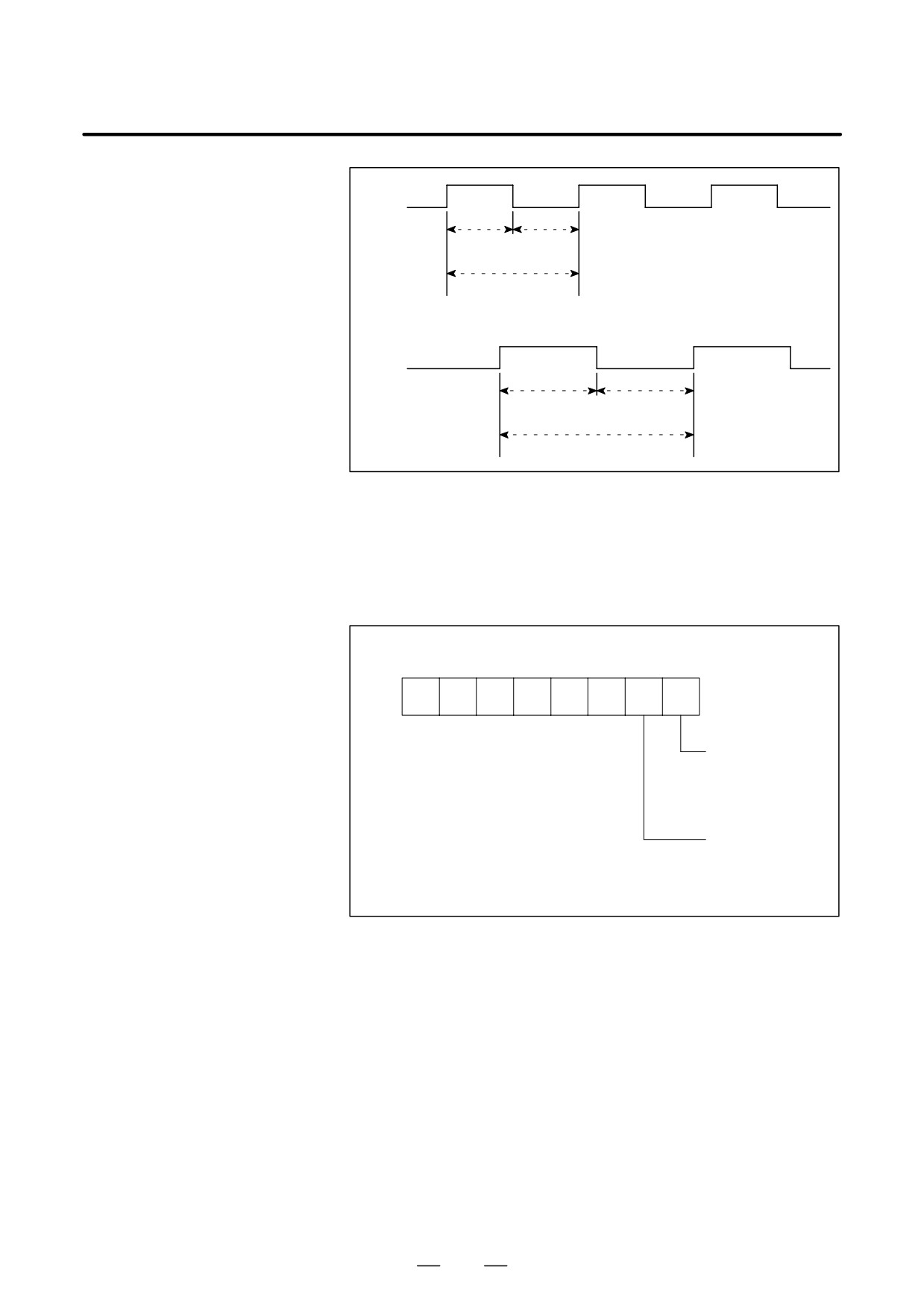
(4) R9091 (System timer)
4 signals can be used as system timer.
The specifications of every signal are as following.
#7
#6
#5
#4
#3
#2
#1
#0
R9091
always OFF
always ON
Cyclic signal of 200
ms (104 ms ON, 96
ms OFF)
Cyclic signal of 1 se-
cond. (504 ms ON,
496 ms OFF)
CAUTION
Each signal is initially off. R9091.0 and R9091.1 are set
cyclically at the beginning of the first ladder level.
Each signal (ON-OFF signal) has an accuracy of "8 ms.
291
4. INTERFACE BETWEEN CNC AND PMC
B-64115EN/02
R9091.5
104ms
96ms
200ms
R9091.6
504ms
496ms
1s
(5) Ladder execution start signal, ladder stop signal, ladder execution
state signal (PMC-SB7)
1
Ladder execution start signal and latter stop signal
With the ladder execution start signal or the ladder stop signal, the
start or stop of a ladder program can be known in the ladder
program.
#7
#6
#5
#4
#3
#2
#1
#0
R9015
R9015.0: Ladder
execution start sig-
nal (reference only
from the ladder pro-
gram)
R9015.1: Ladder
execution start sig-
nal (reference only
from the ladder pro-
gram)
2
Ladder execution state signal
The state of ladder program execution or PMCC language program
execution can be known by referencing the ladder execution state
signal from an external system or program such as the network
board, C executor program, FOCAS1 Ethernet, and HSSB library.
292
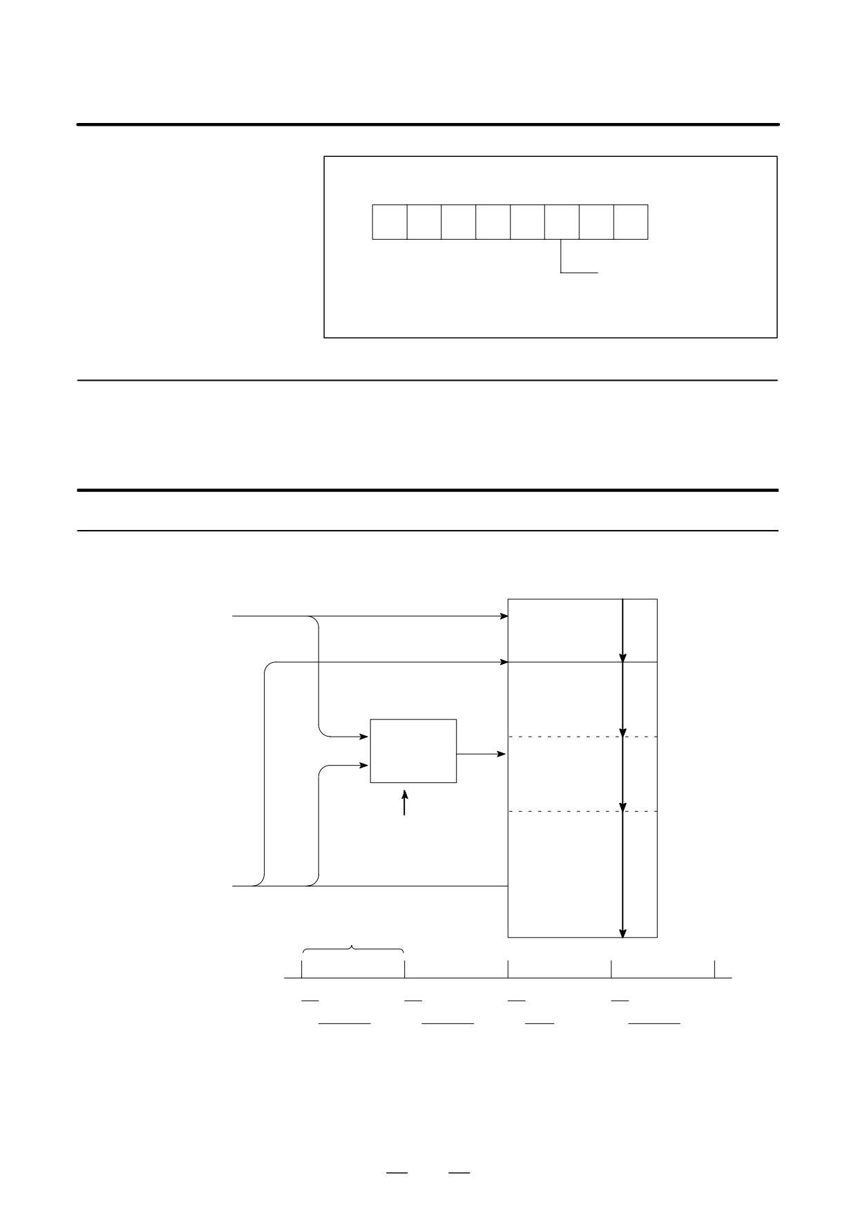
B-64115EN/02
4. INTERFACE BETWEEN CNC AND PMC
#7
#6
#5
#4
#3
#2
#1
#0
R9015
R9091.2: Ladder execution
state signal
0: Ladder stopped
1: Ladder being executed
4.2.4
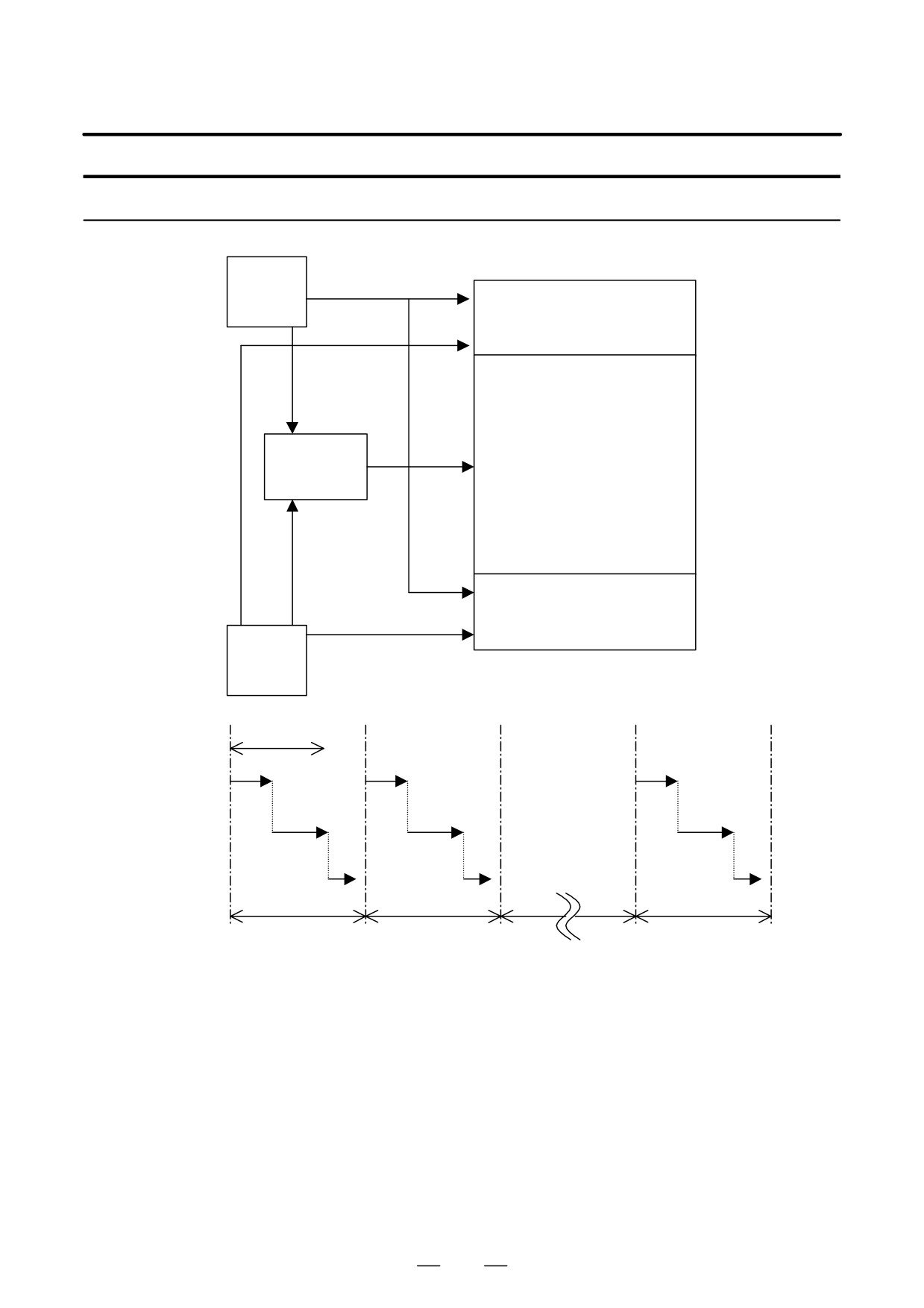
Execution Period of
PMC
For PMC-SA1
Sequence program
1st level
From NC
(High-speed se-
(1)
quence)
END1
2nd level
(Normal sequence)
(2)-1
Synchronized
buffer
(2)-2
Head of 2nd level
(2)-n
From MT
END2
8msec
Period
(1)
(1)
(1)
(1)
1st level
(2)-1
(2)-2
(2)-n
(2)-1
2nd level
293
4. INTERFACE BETWEEN CNC AND PMC
B-64115EN/02
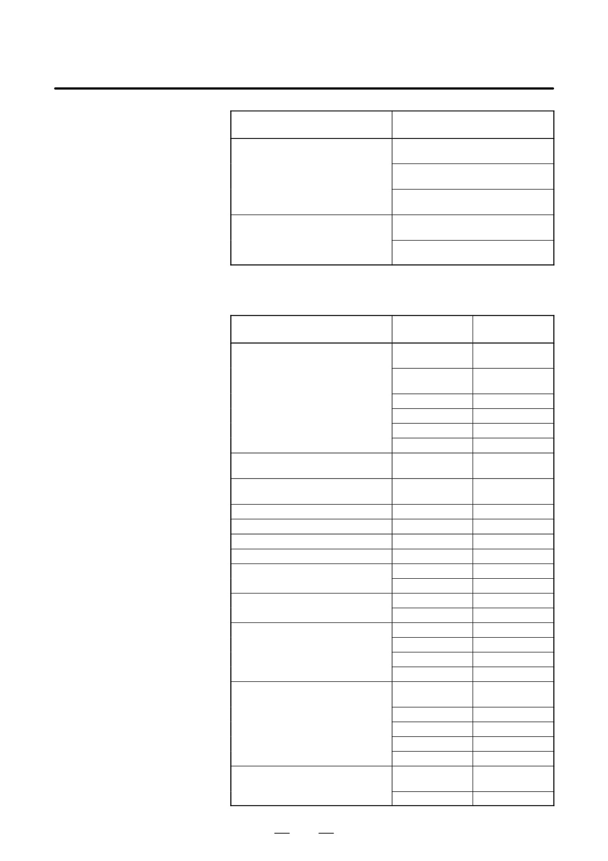
For PMC-SB7
CNC (F)
1st level
END1
2nd level
Synchronized
buffer
END2
3rd level
END3
Machine (X)
From NC
Ladder execution time
1st level
Division 1
Division 2
Division n
2nd level
3rd level
8ms
8ms
8ms
The ratio of the 1st level execution time to the 2nd level execution time
is set in a system parameter for ladder execution time.
D For a ladder that uses the 1st level and the 2nd level only, set the upper
limit (150).
294

B-64115EN/02
4. INTERFACE BETWEEN CNC AND PMC
D For a ladder that uses the 3rd level, the setting of the upper limit (150)
may not ensure full 3rd level operation. In such a case, set this
parameter so that the processing times of the 1st level and 2nd level
are reduced.
The 1st ladder level or the 2nd ladder level processing time is determined
by the following expression:
The 1st ladder level or
Ladder execution time
= 5msec
2nd ladder level processing time
100
The 3rd ladder level processing time is determined by the following
expression:
The 3rd ladder level processing time =
7.5 msec - (1st ladder level
and 2nd ladder level
processing times)
4.2.5
I/O Module Assignment
(a) Input modules
Name List
Module name
Input format
(Actual module name)
Non-insulation type
ID32A
DC input
(AID32A)
ID32B
(AID32B)
Non-insulation type
ID16C
DC input
(AID16C)
ID16D
(AID16D)
ID32E
(AID32E)
ID32F
(AID32F)
Non-insulation type
IA16G
DC input
(AIA16G)
(b) Output modules
Module name
Input format
(Actual module name)
Insulation type
OD08C
DC input
(AOD08C)
OD08D
(AOD08D)
OD16C
(AOD16C)
OD16D
(AOD16D)
OD32C
(AOD32C)
OD32D
(AOD32D)
295
4. INTERFACE BETWEEN CNC AND PMC
B-64115EN/02
Module name
Input format
(Actual module name)
AC output
OA05E
(AOA05E)
OA08E
(AOA08E)
OA12E
(AOA12E)
Relay output
OA08G
(AOA08G)
OA16G
(AOA16G)
(c) Other modules
Occupied
Name
Module name
address
FANUC CNC SYSTEM
FS04A
Input 4 bytes
FANUC Power Mate
Output 4 bytes
FS08A
Input 8 bytes
Output 8 bytes
OC02I
Input 16 bytes
OC02O
Output 16 bytes
OC03I
Input 32 bytes
OC03O
Output 32 bytes
Analog input module
AD04A
Input 8 bytes
(AAD04A)
Analog output module
DA02A
Output 4 bytes
(ADA02A)
Connection unit (1 unit)
CN01I
Input 12 bytes
Connection unit (1 unit)
CN01O
Output 8 bytes
Connection unit (2 units)
CN02I
Input 24 bytes
Connection unit (2 units)
CN02O
Output 16 bytes
Operator’s panel connection unit
OC01I
Input 12 bytes
I/O card E
OC01O
Output 8 bytes
Operator’s panel connection unit
/8
Input 8 bytes
I/O card D
/4
Output 4 bytes
Machine operator’s panel interface unit
OC02I
Input 16 bytes
OC02O
Output 16 bytes
OC03I
Input 32 bytes
OC03O
Output 32 bytes
I/O Link connection unit
/j
Input j bytes
Output j bytes
OC02I
Input 16 bytes
OC02O
Output 16 bytes
OC03I
Input 32 bytes
OC03O
Output 32 bytes
For I/O Unit MODEL B
#j
Input j bytes
Output j bytes
##
Input 4 bytes
296
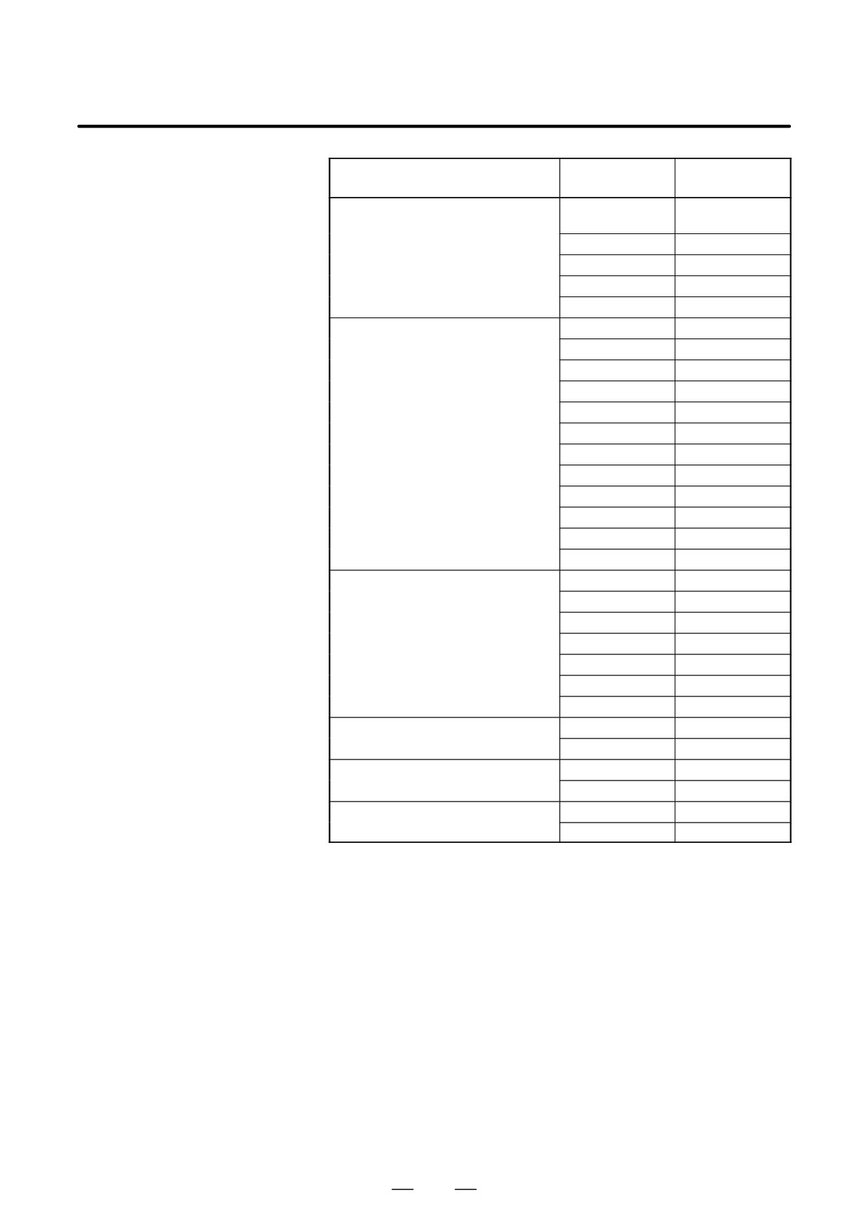
B-64115EN/02
4. INTERFACE BETWEEN CNC AND PMC
Occupied
Name
Module name
address
Special module
/j
input j bytes
output j bytes
OC02I
Input 16 bytes
OC02O
Output 16 bytes
OC03I
Input 32 bytes
OC03O
Output 32 bytes
Module for distributed I/O and distribution
CM03I(/3)
Input 3 bytes
panel I/O
CM06I(/6)
Input 6 bytes
CM09I
Input 9 bytes
CM12I(OC01I)
Input 12 bytes
CM13I
Input 13 bytes
CM14I
Input 14 bytes
CM15I
Input 15 bytes
CM16I(OC02I)
Input 16 bytes
CM02O(/2)
Output 2 bytes
CM04O(/4)
Output 4 bytes
CM06O(/6)
Output 6 bytes
CM08O(/8)
Output 8 bytes
Module for distributed I/O and distribution
CM06I(/6)
Input 6 bytes
panel I/O
CM13I
Input 13 bytes
CM14I
Input 14 bytes
CM15I
Input 15 bytes
CM16I(OC02I)
Input 16 bytes
CM04O(/4)
Output 4 bytes
CM08O(/8)
Output 8 bytes
External I/O card A,D for Power Mate
/6
Input 6 bytes
/4
Output 4 bytes
External I/O card B,E for Power Mate
OC01I
Input 12 bytes
OC01O
Output 8 bytes
Built-in I/O Card for Series 0i-B
CM16I(OC02I)
Input 16 bytes
CM08O(/8)
Output 8 bytes
297
4. INTERFACE BETWEEN CNC AND PMC
B-64115EN/02
4.3
PMC SCREEN
(PMC-SA1)
4.3.1
PMC Menu Selection
Procedure Using Soft
Keys
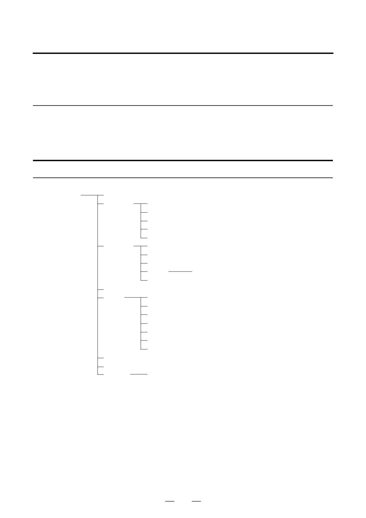
PMC-SA1 screen menu selection procedure
[PMC]
[PMCLAD]
Ladder diagram display screen
[PMCDGN]
[TITLE]
Title screen
[STATUS]
Signal status screen
[ALARM]
Alarm screen
[TRACE]
Trace function
[IOCHK]
I/O check screen
[PMCPRM]
[TIMER]
Timer screen
[COUNTR]
Counter screen
[KEEPRL]
Keep relay screen
[DATA]
[G.DATA]
Data table screen
[SETING]
Setting screen
[RUN]/[STOP]
Ladder start/stop
[EDIT]
[TITLE]
Title editing screen
[LADDER]
Ladder diagram editing screen
[SYMBOL]
Symbol/comment editing screen
[MESAGE]
Message editing screen
[MODULE]
I/O unit address setting screen
[CROSS]
Cross reference screen
[CLEAR]
Clear screen
[I/O]
Program/parameterinput/output screen
[SYSPRM]
System parameter screen
[MONIT]
[ONLINE]
Online setting screen
298
B-64115EN/02
4. INTERFACE BETWEEN CNC AND PMC
4.3.2
(1) Display method
Dynamic Display of
1
Press the
SYSTEM
key, then press the soft key [PMC].
Sequence Program
2
Dynamic display of sequence program by pressing [PMCLAD]
soft key.
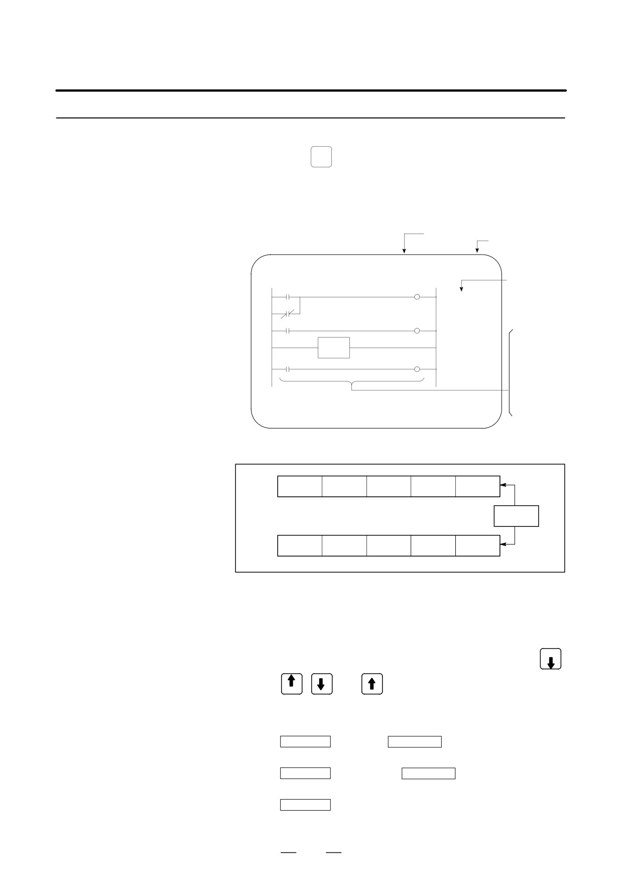
(2) Display information
Display of current net number
RUN/STOP
status
LADDER
NET 0001-0004 MONIT RUN
Comment
LOG1
LOG1
ALWAYS1
LOG1
X008.4
*ESP
EMERGENCY
STOP
Green
color
END1
(dark) :
PORD
POR
Signal is
POWER ON
turned
RESET
ON
White color
(bright) :
Signal is
turned ON
[
SEARCH ]
[ ADRESS ]
[ TRIGER ]
[WINDOW ]
[
]
D
Soft key
SEARCH
ADRESS
TRIGER
WINDOW
NEXT
DUMP
DPARA
(3) Searching for the signal (SEARCH)
1
Press the [SEARCH] soft key.
2
Using the following keys as described below, search for desired
signal.
D The signals being displayed can be changed by using the PAGE
,
,
, and
keys.
PAGE
D [TOP]: Locates the top of the ladder program.
D [BOTTOM] : Locates the end of the ladder program.
D
Address.bit
[SRCH] or
Single name
[SRCH] :
Search a specified address unconditionally.
D
Address.bit
[W-SRCH] or
Single name
or [W-SRCH] :
Searches for a specified address, for the write coils.
D
Net number
[N-SRCH]:
Displays the ladder program from the specified net address.
299
4. INTERFACE BETWEEN CNC AND PMC
B-64115EN/02
D
Function instruction number
[F-SRCH] or
Function instruction name
[F-SRCH]: Searches for the specified
function instruction.
D [ADRESS]:
Displays the address and bit number of the specified signal.
D [SYMBOL]:
Displays the symbol of the specified signal. (The address of the
specified signal is displayed if a symbol was not specified when
the program was created.)
(4) Turning off the monitor display when the trigger signal changes
(TRIGER)
When the preset trigger signal changes, the system turns off the
monitor display. By using this function, the states of all signals can
be accurately read when the trigger signal changes.
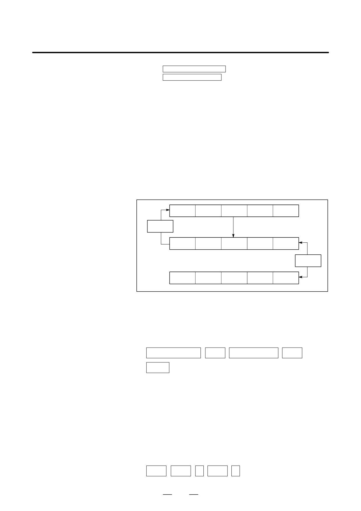
1
Press the [TRIGER] soft key.
SEARCH
ADRESS
TRIGER
WINDOW
RET
TRGON
TRGOFF
START
NEXT
DUMP
DPARA
TRGSRC
INIT
2
Press the [INIT] soft key to initialize the trigger parameters.
3
Specify the trigger conditions.
D To turn off the monitor display at the signal’s rising edge (as the
signal changes from 0 to 1), enter the desired data and press the
required keys in the order shown below.
Signal name/address
EOB
Trigger checkpoint
EOB
Count
[TRGON]
: Trigger checkpoint:
0: Before the first level of the ladder program is executed
1: After the first level of the ladder program is executed
2: After the second level of the ladder program is executed
3: After the third level of the ladder program is executed
Example) To set the system so that it turns off the monitor display
when the external reset signal (ERS) is input three times,
enter the required data and press the required keys in the
order shown below:
ERS
EOB
2
EOB
3
[TRGON]
300
B-64115EN/02
4. INTERFACE BETWEEN CNC AND PMC
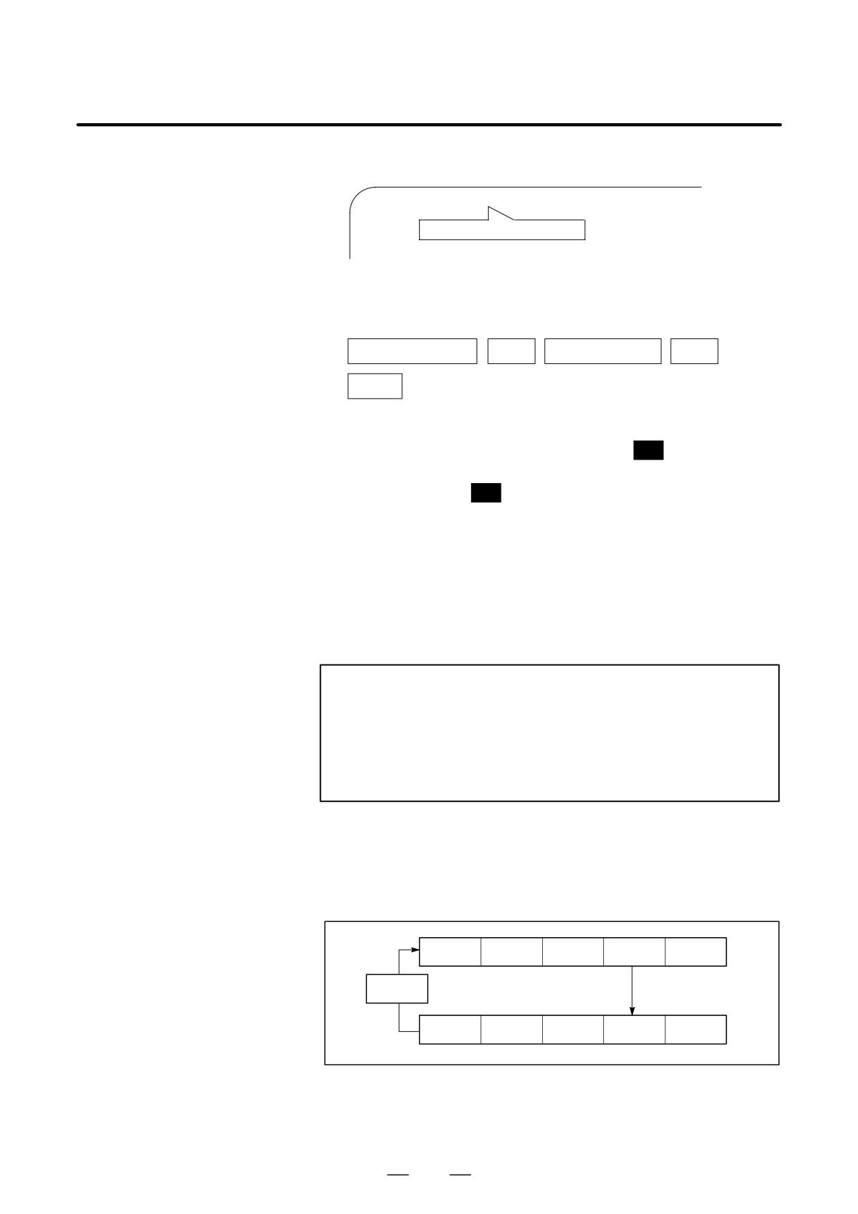
The specified trigger conditions are displayed at the top of the screen.
TRIGER *MODE : ON G008. 7 : 2 : 003 NET 0001-00005
Specified conditions are displayed.
To turn off the monitor display at the signal’s falling edge (as the signal
changes from 1 to 0), enter the desired data and press the required keys
in the order shown below.
Signal name/address
EOB
Trigger checkpoint
EOB
Count
[TRGOFF]
4
Press the [START] soft key to activate the trigger function.
³ While the trigger function is operating, TRG is displayed at the
lower right corner of the screen. When the trigger conditions
are satisfied, TRG disappears and the monitor screen is locked.
5
To interrupt the trigger function, press the [STOP] soft key while
the function is effective.
³ In this case, the specified trigger conditions remain effective.
Pressing the [START] soft key reinstates the trigger function.
6
To search for the instruction where the program was stopped by the
trigger function and blink that instruction, press the [TRGSRC]
soft key.
NOTE
1
Because parameters are stored in the nonvolatile memory,
they are not lost even if the power is turned off.
2
When bit 2 of keep relay K18 is set to 1 after parameters for
sampling are specified, the trigger function automatically
starts when the power is turned on.
(5) Displaying a divided ladder program (WINDOW)
A ladder program can be divided into up to six sections, and the
individual sections displayed on the screen simultaneously.
1
Press the [WINDOW] soft key.
SEARCH
ADRESS
TRIGER
WINDOW
RET
DIVIDE
CANCEL
DELETE
SELECT
WIDTH
2
Press the [DIVIDE] soft key to divide the dynamic display screen
into the desired number of sections.
: Each time the key is pressed, the screen is divided.
301
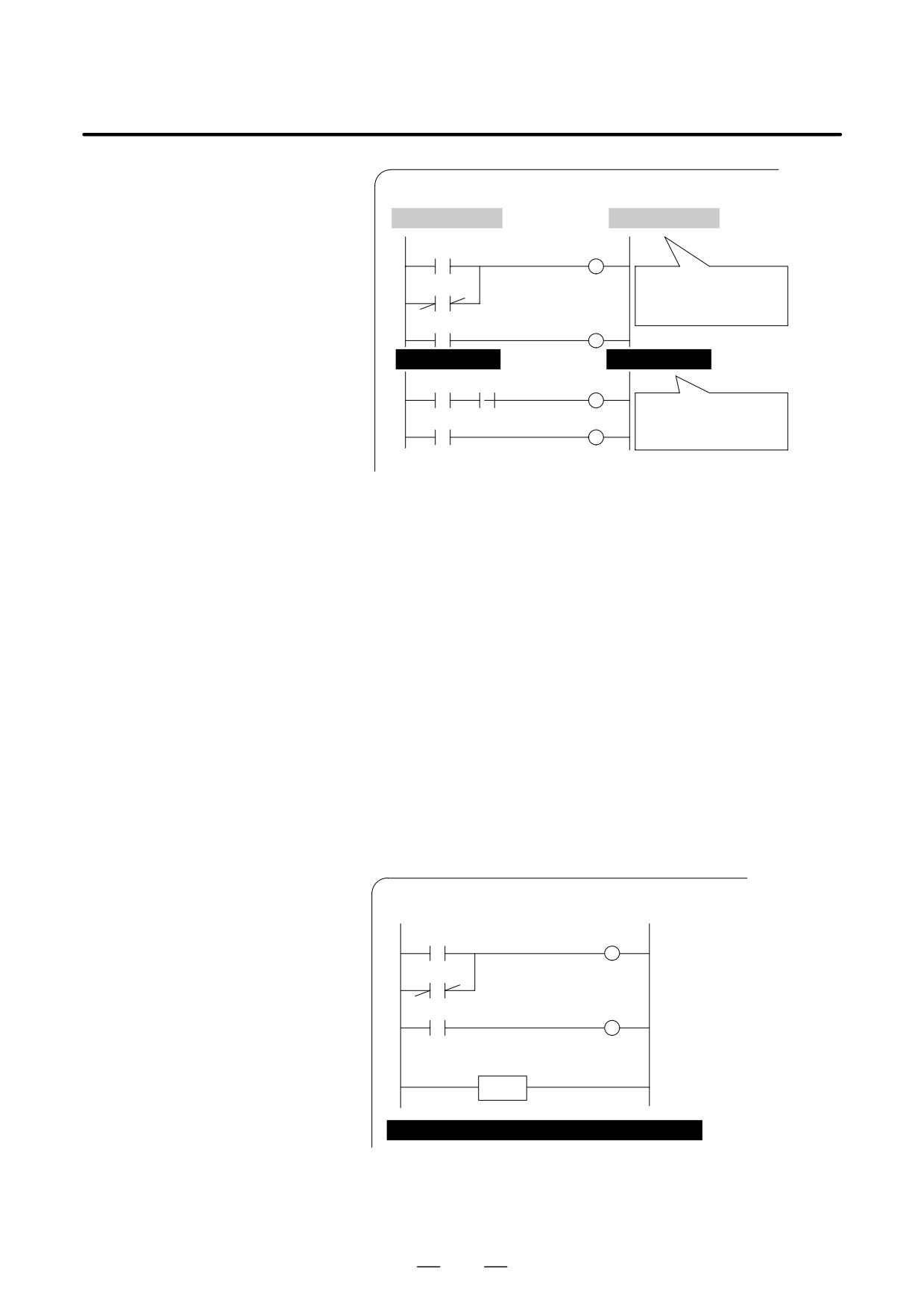
4. INTERFACE BETWEEN CNC AND PMC
B-64115EN/02
LADDER
* XXX
XXX * MONIT RUN
NET 0001-0002
LOG1
LOG1
LOG1
An unselected divided screen
is indicated by a blue low-in-
tensity bar.
*SP.
*SP
NET 0020-0021
DOOR. ST.
ST
A selected divided screen is
SKIP1.
SKIP1
indicated by the purple high-in-
tensity bar.
3
To select the desired divided screen, press the [SELECT] soft key
as many times as necessary to move the purple bar to the desired
screen.
: The normal search function can be used within each divided
screen.
4
To change the width of a selected divided screen, press the
[WIDTH] soft key.
D Pressing the [EXPAND] soft key increases the number of lines
displayed on a divided screen.
D Pressing the [SHRINK] soft key decreases the number of lines
displayed on a divided screen.
5
To terminate the display of a selected divided screen, press the
[DELETE] soft key.
: To terminate screen division, press the [CANCEL] soft key.
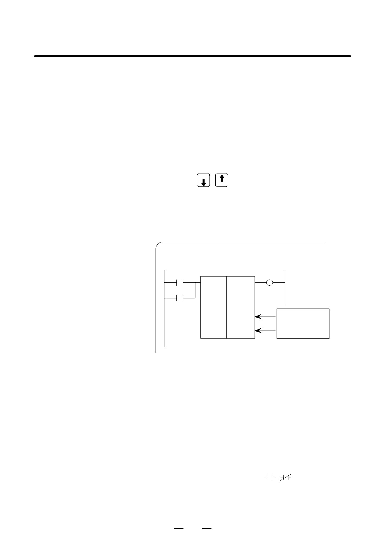
(6) Dumping (DUMP)
The states of the signals corresponding to a ladder program can be
displayed in hexadecimal, together with the ladder program itself.
1
Press the [DUMP] soft key.
LADDER
* XXX
XXX * NET 0001-0004 MONIT RUN
LOG1
LOG1
LOG1 C1
LOG1
*ESP.
*ESP
EMERGENCY STOP
END1
ADDRESS DUMP
G0000
00 1A5C32 22 0D65 10 01 02 00 10 00 00 10 40
G0016
01 001023400F 03 20 1AFF00 00 3A9B16 84
: When the screen is divided, the states of the signals are displayed
in the lower divided screen.
302
B-64115EN/02
4. INTERFACE BETWEEN CNC AND PMC
D To change the data notation
[BYTE] : Data is displayed in units of bytes.
Example) G0000 00 16 84 00 ...
[WORD] : Data is displayed in units of two bytes.
Example) G0000 1600 0084 ...
[D.WORD] : Data is displayed in units of two words, or four
bytes.
Example) G0000 00841600 ...
: When WORD or D.WORD is specified, data is displayed
with the high-order byte placed first.
D To search for an address
Use the PAGE
,
, and [SRCH] keys, as in the normal search
PAGE
function.
(7) Displaying the function-instruction parameters (DPARA/NDPARA)
The states of the control parameters used in function instructions are
displayed together with the ladder program.
1
Press the [DPARA] soft key.
LADDER
* XXX
XXX * NET 0001-0004 MONIT RUN
RST
ERR1
JOG FEEDRATE
SUB 27
2
JOG
CODEB
6
R002
[
4]
The current value of a
control parameter is
G014
displayed below the pa-
[
800]
rameter.
: The data notation (binary or BCD) varies with the function
instructions.
2
To terminate the display of parameters, press the [NDPARA] soft
key.
(8) Editing the program being executed (ONLEDT: on-line editing)
A sequence program can be edited while a program is being executed,
without stopping its execution.
: This function is available only while the edit function is enabled.
1
Press the [ONLEDT] soft key to start the on-line editing function.
The cursor appears on the screen.
2
Modify the program, following the usual editing procedure.
The following changes can be made by means of on-line editing.
D Changing the type of contacts (
,
)
D Changing the addresses of contacts and coils
D Changing the addresses of control parameters used in function
instructions
303

4. INTERFACE BETWEEN CNC AND PMC
B-64115EN/02
: The operations that can be performed in on-line editing are
restricted to those that do not change the memory size of the
program. To perform other operations, such as addition,
insertion, and deletion, use the ordinary editing function.
3
To terminate on-line editing, press the
key.
: Changes made in on-line editing are temporary. To save a
changed program, set K18.3 to 1 or transfer the program to the
DRAM by using the COPY function from the I/O screen. To
enable the use of the program when the system is next turned on,
write it to the FROM from the I/O screen.
PMCPRM
#7
#6
#5
#4
#3
#2
#1
#0
K018
ÇÇÇ
ÇÇÇ
#3
0 :
The ladder program is not transferred to the RAM after on-line
editing.
³ To transfer the program, press the following keys in the order
shown, using the COPY function from the I/O screen:
[COPY], [EXELAD], [EXEC]
1:
A ladder program is automatically transferred to the RAM after
on-line editing.
4.3.3
Display of PMC
(1) Display method
Diagnosis Screen
SYSTEM
1
Press the
key.
2
Press the [PMC] soft key.
3
Display of PMC diagnosis screen by pressing [PMC/DGN] soft
key.
4.3.3.1
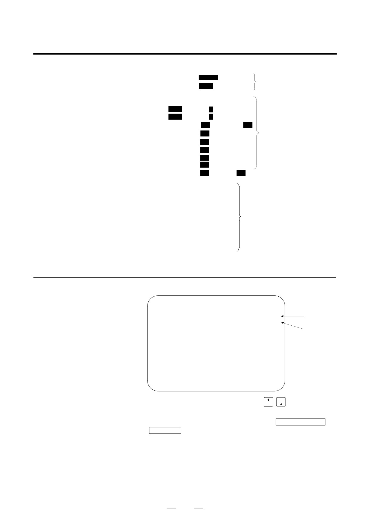
Display of the title data which is wrote at the ladder programming time.
Title screen (TITLE)
PMC TITLE DATA #1
MONIT RUN
PMC PROGRAM NO. :
EDITION NO.
:
PMC CONTROL PROGRAM
SERIES : 408B EDITION : 01
(SERIES : EDITION :
)
PMC TYPE CONTROL : RB5 PROGRAM : RB5
MEMORY USED : KB
LADDER
:
KB
SYMBOL
:
KB
MESSAGE
:
KB
SCAN TIME
:
MS
SCAN MAX
:
MS MIN :
MS
[ TITLE
]
[ STATUS
]
[
ANALYS
]
[
TRACE
]
[
]
304
B-64115EN/02
4. INTERFACE BETWEEN CNC AND PMC
1) 1st page
PMC PROGRAM NO. :
Set at
LADDER
EDITION NO.
:
programmingtime.
PMC CONTROL PROGRAM
SERIES :
EDITION :
(SERIES:
EDITION :
)
Display of a serial
PMC TYPE CONTROL :
PROGRAM :
number and version
MEMORY USED
:
KB
number of PMC
LADDER
:
KB
control software, used
memory area and
SYMBOL
:
KB
scan time.
MESSAGE
:
KB
SCAN TIME
:
MS
SCAN MAX
:
MS MIN :
MS
2) 2nd page
MACHINE TOOL BUILDER NAME :
MACHINE TOOL NAME :
CNC & PMC TYPE NAME :
Set at LADDER
PROGRAM DRAWING NO. :
diagramprogramming
time.
3) 3rd page
DATE OF PRGRAMMING :
PROGRAM DESIGNED BY :
ROM WRITTEN BY :
REMARKS :
4.3.3.2
Display of ON/OFF condition for I/O signals, internal relays, etc.
Status screen (STATUS)
PMC SIGNAL STATUS
MONIT RUN
ADDRESS
7
6
5
4
3
2
1
0
Signal
ED7
ED6
ED5
ED4
ED3
ED2
ED1
ED0
name
G0000
0
0
0
0
1
0
1
0
ED15 ED14 ED13 ED12 ED11 ED10 ED9
ED8
Status
G0001
0
0
0
0
0
0
0
0
of
ESTB EA6
EA5
EA4
EA3
EA2
EA1
EA0
signal
G0002
0
0
0
0
0
0
0
0
0 : OFF
1 : ON
G0003
0
0
0
0
0
0
0
0
FIN
G0003
0
0
0
0
0
0
0
0
[SEARCH]
[
]
[
]
[
]
[
]
PAGE
1
Search the diagnosis number by pressing
PAGE
keys.
2
Searching the specified address or signal name by pressing
[SEARCH] soft key when inputted of
Address and number
or
Single name
305

4. INTERFACE BETWEEN CNC AND PMC
B-64115EN/02
4.3.3.3
Display of an alarm when an alarm occurred in PMC program.
Alarm screen (ALARM)
PMC ALARM MESSAGE
MONIT RUN
ALARM NOTHING
[ TITLE
]
[ STATUS
]
[
ALARM
]
[
TRACE
]
[
]
See Appendix A.2 for details of the alarms.
Record the signal status to the trace memory when the specified signal is
4.3.3.4
changed.
Trace screen (TRACE)
(1) Trace parameter screen (TRCPRM)
PMC SIGNAL TRACE
MONIT RUN
TRACE MODE
:
(0:1BYTE/1:2BYTE/2:WORD)
1ST TRACE ADDRESS CONDITION
ADDRESS TYPE
:
(0:PMC/1:PHY)
ADDRESS
:
MASK DATA
2ND TRACE ADDRESS CONDITION
ADDRESS TYPE
:
(0:PMC/1:PHY)
ADDRESS
:
MASK DATA
:
[ T.DISP ]
[
EXEC ]
[
]
[
]
[
]
(a) TRACE MODE: Select the trace mode.
0= 1 byte address signal trace
1= Independent 2 byte address signal trace
2= Continuous 2 byte address signal trace
(b) ADDRESS TYPE: 0= Set the trace address by PMC address
1= Set the trace address by physical address
(Using mainly by C language)
(c) ADDRESS :
Set the trace address
(d) MASK DATA :
Specify the trace bit by hexadecimal code.
For example, set the “E1” when trace the bit
7, 6, 5 and 0. Not execute the tracing when the
bit 4, 3, 2 and 1 is changed, but, the signal
status should recorded at tracing time.
(e.g)
#7 #6
#5
#4
#3
#2
#1
#0
1
1
1
0
0
0
0 1:E1
306

B-64115EN/02
4. INTERFACE BETWEEN CNC AND PMC
Ơ Correspond table between binary and hexadecimal code ơ
00002 : 016
00012 : 116
00102 : 216
00112 : 316
01002 : 416
01012 : 516
01102 : 616
01112 : 716
10002 : 816
10012 : 916
10102 : A16
10112 : B16
11002 : C16
11012 : D16
11102 : E16
11112 : F16
(e) [EXEC] soft key :
Start of tracing.
Clear the trace memory and trace memory contents are update
when the specified signal are changed from previous ones.
The trace memory are always maintained up to the previous results
for 256 bytes from the latest ones regardless of the time lapse.
(2 byte tracing = 128 times.)
(f) [T.DISP] soft key : Display of trace memory contents.
(2) Trace memory screen (T.DISP)
PMC SIGNAL TRACE
MONIT RUN
Trace address and
1ST ADDRESS=X008(E1)
2ND ADDRESS=G000(FF)
mask data in ( )
NO.
7 6 5 4 3 2 1
0 7 6 5 4 3 2 1 0
0000
0001
1 0 0 0 0 0 1
1 0 0 0 0 0 0 0 0
0002
1 1 0 0 0 0 0
0 0 0 0 0 0 0 0 0
0003
0 1 0 0 0 0 0
0 0 0 0 0 0 0 0 0
Newest status
0004
⋅(Period):off
1/I:on
0005
0006
0007
0008
[
TRCPRM
]
[ STOP ]
[
]
[
]
[
]
[TRCPRM] soft key
:
Return to trace parameter setting screen
[STOP] soft key
:
Stop the trace operation.
[EXEC] soft key
:
Re-start of tracing (Clear the memory).
307
4. INTERFACE BETWEEN CNC AND PMC
B-64115EN/02
4.3.4
PMC Parameter
4.3.4.1
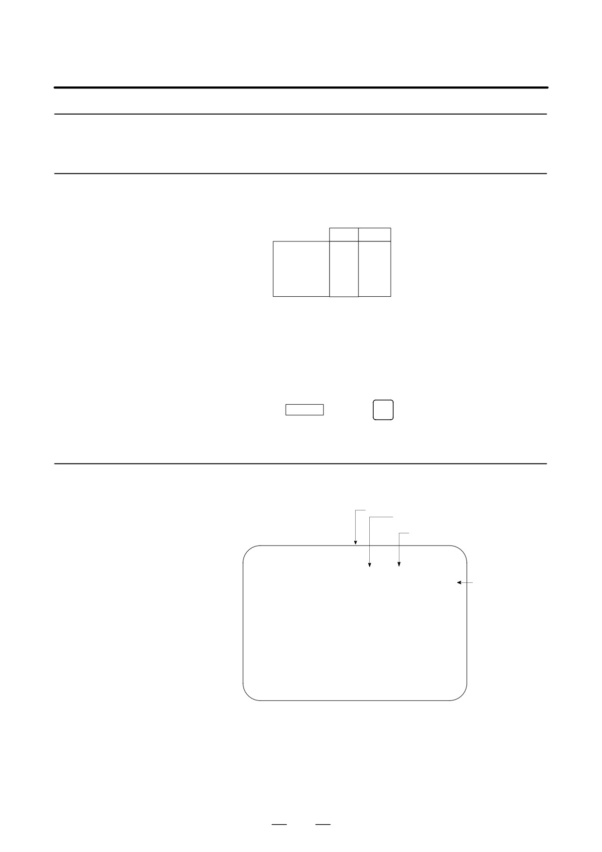
1
Select MDI mode or depress EMERGENCY STOP button.
Input of PMC parameter
2
[PWE] set to “1” on SETTING screen or PROGRAM PROTECT
signal (KEY4) turn to “1”.
from MDI
PWE
KEY4
Timer
f
Counter
f
f
either one
Keep relay
f
Data table
f
f
either one
3
Select the display screen by soft key.
[TIMER]
: Timer screen
[COUNTER] : Counter screen
[KEEPRL]
: Keep relay screen
[DATA]
: Data table screen
4
Move the cursor to desired number.
5
Input the
Numeral
and press
INPUT
key then the data inputted.
6
[PWE] on SETTING screen or [KEY4] return to “0” after data set.
4.3.4.2
This screen is used for setting timer time of the Timer instruction (SUB
3).
Timer screen (TIMER)
Page number (change by page cursor key)
Timer number specified with the Tim-
er instruction
Refer the address by ladder
program
PMC PARAMETER (TIMER) #001
MONIT RUN
NO. ADDRESS
DATA
NO. ADDRESS DATA
01
T00
480
11
T20
0
Setting time by
02
T02
960
12
T22
0
msec unit
03
T04
0
13
T24
0
04
T06
0
14
T26
0
05
T08
0
15
T28
0
06
T10
0
16
T30
0
07
T12
0
17
T32
0
08
T14
0
18
T34
0
09
T16
0
19
T36
0
10
T18
0
20
T38
0
[ TIMER ]
[
COUNTR
]
[
KEEPRL
]
[
DATA
]
[
SETING
]
Setting time : Timer No. 1 - 8 =Max.=1572.8 sec, each 48msec.
Up to 262.1 seconds in units of 8 ms for timer
Nos. 9 to 40 subsequent timers
308
B-64115EN/02
4. INTERFACE BETWEEN CNC AND PMC
4.3.4.3
Set and display the preset values and integrated values of the counter
instruction (SUB 5).
Counter screen
(COUNTER)
Page number (change by page cursor key)
Preset value (MAX. value)
(The min. value specified in the
program)
Integrated value
PMC PARAMETER (COUNTER) #001
MONIT RUN
NO.
ADDRESS
PRESET
CURRENT
01
C00
100
1
02
C04
50
2
03
C08
0
0
Up to 32767
04
C12
0
0
can be set for
05
C16
0
0
PRESET and
06
C20
0
0
CURRENT for
07
C24
0
0
counter Nos. 1
08
C28
0
0
to 20
09
C32
0
0
10
C36
0
0
[ TIMER ]
[COUNTR]
[
KEEPRL
]
[
DATA
]
[
SETING
]
Refer the address by ladder program
Specified counter number by program
4.3.4.4
Keep relay screen
Refer the address by ladder program
(KEEPRL)
PMC PARAMETER (KEEP RELAY)
MONIT STOP
NO. ADDRESS
DATA
NO. ADDRESS
DATA
01
K00
00000000
11
K10
00000000
02
K01
00000000
12
K11
00000000
03
K02
00000000
13
K12
00000000
04
K03
00000000
14
K13
00000000
05
K04
00000000
15
K14
00000000
06
K05
00000000
16
K15
00000000
07
K06
00000000
17
K16
00000000
08
K07
00000000
18
K17
00000000
09
K08
00000000
19
K18
00000000
10
K09
00000000
20
K19
00000000
[TIMER]
[COUNTR]
[KEEPRL]
[DATA]
[SETING]
i) Control of battery-powered memory
#7
#6
#5
#4
#3
#2
#1
#0
K16
MWRTF2
MWRTF1
#7 MWRTF2: This operation is performed for checking the writing status of the
nonvolatile memory.
#6 MWRTF1: Write status for battery-powered memory
309