FANUC Series 0i-MODEL C, Series 0i Mate-MODEL C. MAINTENANCE MANUAL - page 4
1. DISPLAY AND OPERATION
B-64115EN/02
#2(DUA):
0 : The slave of interest is not on the first axis of the two-axis amplifier.
1 : The slave of interest is on the first axis of the two-axis amplifier.
#3(EXT):
0 : The slave of interest does not exist.
1 : The slave of interest exists.
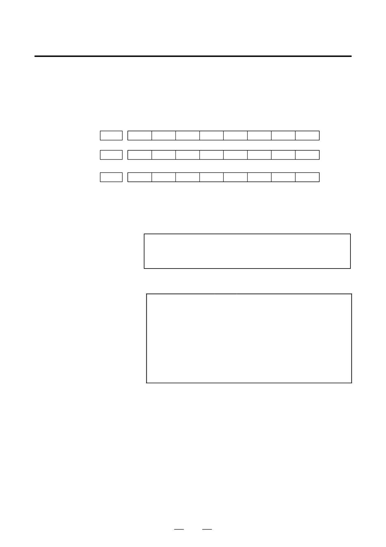
#7
#6
#5
#4
#3
#2
#1
#0
DGN
331
DMA
TP1
TP0
HA2
HA1
HA0
#7
#6
#5
#4
#3
#2
#1
#0
DGN
333
DMA
TP1
TP0
HA2
HA1
HA0
to
#7
#6
#5
#4
#3
#2
#1
#0
DGN
349
DMA
TP1
TP0
HA2
HA1
HA0
#0, #1, #2(HA0, HA1, HA2):
Indicates the host LSI address specified as a DMA destination.
#3, #4 (TP0, TP1):
Indicates the type code of a specified slave.
(See the above descriptions about ST0 and ST1.)
#5(DMA):
Indicates a value determining whether to allow DMA to occur.
NOTE
A combination of parameter Nos. 330 and 331 corresponds
to one FSSB slave unit. Up to ten slave units are available.
Slave units and the associated diagnosis numbers
Slave unit 00
³
Diagnosis No. 330, No. 331
Slave unit 01
³
Diagnosis No. 332, No. 333
Slave unit 02
³
Diagnosis No. 334, No. 335
Slave unit 03
³
Diagnosis No. 336, No. 337
Slave unit 04
³
Diagnosis No. 338, No. 339
Slave unit 05
³
Diagnosis No. 340, No. 341
Slave unit 06
³
Diagnosis No. 342, No. 343
Slave unit 07
³
Diagnosis No. 344, No. 345
Slave unit 08
³
Diagnosis No. 346, No. 347
Slave unit 09
³
Diagnosis No. 348, No. 349
70
B-64115EN/02
1. DISPLAY AND OPERATION
D Details of invalid servo
parameter setting alarms
(on the servo side)
DGN
350
Not used in the FANUC Series
0i/0i Mate-MODEL C.
DGN
351
DGN
352
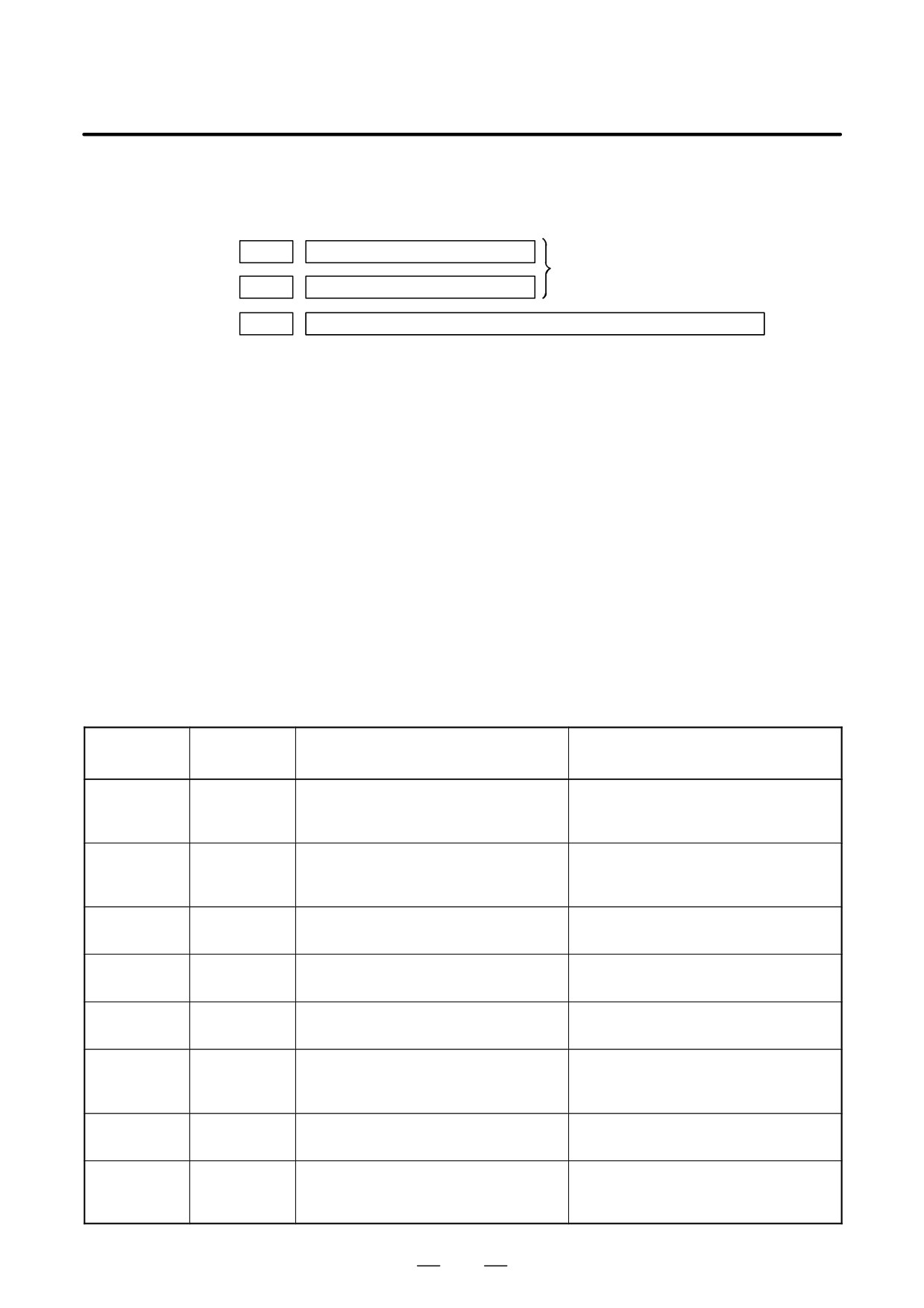
Detail number for invalid servo parameter setting alarm
Indicates information that can be used to identify the location (parameter)
and cause of an invalid servo parameter setting alarm (servo alarm No.
417).
This diagnosis information is valid when the following conditions are
satisfied.
D Servo alarm No. 417 has occurred.
D Bit 4 of diagnosis No. 203 (PRM) = 1
See the following table for the displayed detail numbers and the
corresponding causes. For further detail information that could be used
to take measures, refer to FANUC AC Servo Motor αiS/αiF/βiS series
Parameter Manual (B-65270EN).
D Detailed descriptions
about invalid servo
parameter setting alarms
Detail
Parameter
Cause
Measure
number
number
0233
2023
A value specified as the number of veloc-
Decrease the value specified as the num-
ity pulses is greater than 13100 when ini-
ber of velocity pulses to within 13100.
tialization bit 0 = 1.
0243
2024
A value specified as the number of posi-
Decrease the value specified as the num-
tion pulses is greater than 13100 when
ber of position pulses to within 13100.
initialization bit 0 = 1.
0434
2043
The internal value of the velocity loop in-
Decrease the value specified in the veloc-
0435
tegration gain has overflowed.
ity loop integration gain parameter.
0444
2044
The internal value of the velocity loop pro-
Use a function for changing the internal for-
0445
portional gain has overflowed.
mat of the velocity loop proportional gain.
0474
2047
The internal value of the observer param-
Change the setting to: (-1) × (desired
0475
eter (POA1) has overflowed.
setting)/10
0534
2053
The internal value of the dead zone com-
Decrease the setting until the invalid pa-
0535
pensation parameter has overflowed.
rameter setting alarm will not occur any
longer.
0544
2054
The internal value of the dead zone com-
Decrease the setting until the invalid param-
0545
pensation parameter has overflowed.
eter setting alarm will not occur any longer.
0686
2068
The internal value of the feedforward co-
Use the position gain magnification func-
0687
efficient has overflowed.
tion.
0688
71
1. DISPLAY AND OPERATION
B-64115EN/02
Detail
Parameter
Cause
Measure
number
number
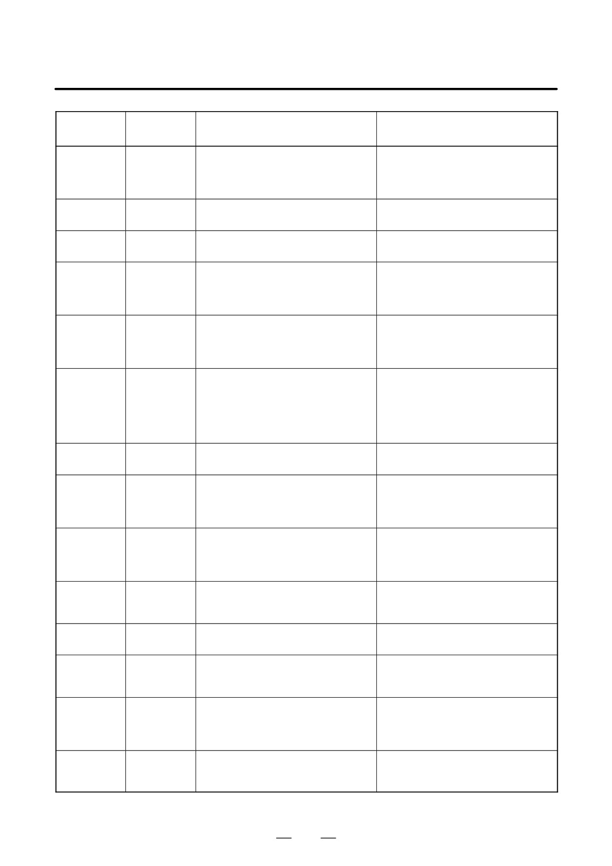
0694
2069
The interval value of the velocity feedfor-
Decrease the velocity feedforward coeffi-
0695
ward coefficient has overflowed.
cient.
0696
0699
0754
2075
The setting of the parameter listed at the
This parameter is presently not in use.
0755
left has overflowed.
Specify 0 in it.
0764
2076
The setting of the parameter listed at the
This parameter is presently not in use.
0765
left has overflowed.
Specify 0 in it.
0783
2078
The conversion coefficient parameter
Set a value in this parameter.
listed at the left has not been set up for a
full-closed loop linear motor (for the Se-
ries 9080 only).
0793
2079
The conversion coefficient parameter
Set a value in this parameter.
listed at the left has not been set up for a
full-closed loop linear motor (for the Se-
ries 9080 only).
0843
2084
No positive value has been set for the
Specify a positive value as the flexible
flexible feed gear numerator.
feed gear numerator.
Alternatively, the following condition ex-
Alternatively, satisfy the following condi-
ists: Feed gear numerator > denominator
tion: Feed gear numerator x denomina-
tor (except for phase A-/B-specific
stand-alone type detector).
0853
2085
No positive value has been set as the
Specify a positive value as the flexible
flexible feed gear denominator.
feed gear denominator.
0884
2088
The internal value of the machine velocity
Decrease the machine velocity feedback
0885
feedback coefficient has overflowed.
coefficient.
0886
Alternatively, use the damping control
function, which has an equivalent effect.
0883
2088
A value of 100 or greater was specified in
The maximum allowable value for the ma-
the machine velocity feedback coefficient
chine velocity feedback coefficient for axes
for an axis with a serial stand-alone type
with a serial stand-alone type detector is
detector.
100. Decrease the setting to within 100.
0926
2092
The interval value of the advance feedfor-
Use the position gain magnification func-
0927
ward coefficient has overflowed.
tion.
0928
0996
2099
The internal value for suppressing N
Decrease the setting of the parameter
pulses has overflowed.
listed at the left.
1123
2112
No value has been entered for the AMR
Specify the AMR conversion coefficient.
conversion coefficient parameter when a
linear motor is in use.
1183
2118
No value has been specified in the semi-/
Specify a semi-/full-closed loop error
full-closed loop error threshold parameter
threshold value for the parameter listed at
for a full-closed loop linear motor (for the
the left.
Series 9080 only).
1284
2128
If the value specified as the number of ve-
Decrease the value for the parameter
1285
locity pulses is small, the internal value of
listed at the left to within a range where no
the current control parameter overflows.
alarm will occur any longer.
72
B-64115EN/02
1. DISPLAY AND OPERATION
Detail
Parameter
Cause
Measure
number
number
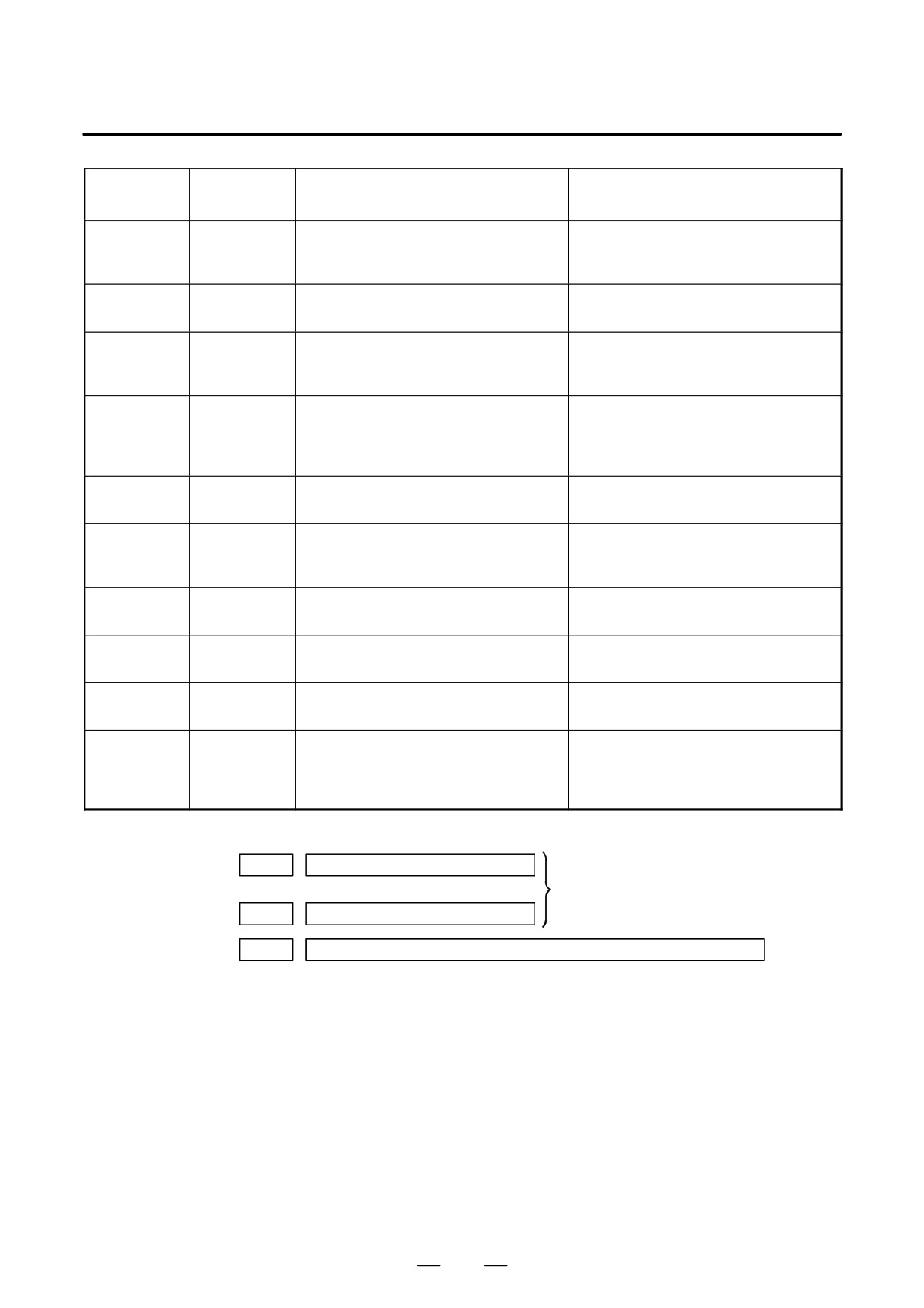
1294
2129
If the value specified as the number of ve-
Re-set “a” to a smaller value when the
1295
locity pulses is large, the internal value of
setting of the parameter listed at the left is
the current control parameter overflows.
broken up into: a × 256 + b
1393
2139
The setting of the linear motor AMR offset
Decrease the setting of the parameter
has exceeded ±45.
listed at the left to within ±45.
1446
2144
The cutting feedforward coefficient for the
Use the position gain magnification func-
1447
cutting-/rapid traverse-specific FAD func-
tion.
1448
tion has overflowed.
1454
2145
The cutting velocity feedforward coeffi-
Decrease the velocity feedforward coeffi-
1455
cient for the cutting-/rapid traverse-spe-
cient.
1456
cific FAD function has overflowed.
1459
8213
1821
No positive value has been set in the ref-
Specify a positive value in the parameter
erence counter capacity parameter.
listed at the left.
8254
1825
The internal value of the position gain has
Use the position gain magnification func-
8255
overflowed.
tion.
8256
10016
2200 bit 0
The internal value of a parameter used to
Do not use the runaway detection func-
10019
detect runaway has overflowed.
tion (specify bit 0 = 1).
10043
1815#1
A full-closed loop has been set up for a
A full-closed loop cannot be specified for
2010#2
linear motor (except for the Series 9080).
linear motors.
10053
2018#0
The scale reverse connection bit has
The scale reverse connection bit cannot
been set up for a linear motor.
be used for linear motors.
10062
2209#4
The amplifier in use does not support the
If you want to use this amplifier, reset the
HC alarm avoidance function.
function bit listed at the left to 0.
If you want to use the HC alarm avoidance
function, use an amplifier that supports it.
D Error detection
DGN
353
Not used in the FANUC Series
to
0i/0i Mate-MODEL C.
DGN
358
DGN
360
Cumulative command pulse count (NC)
[Data type] Two-word axis
[Unit of data] Detection unit
[Valid data range] -99999999 to 99999999
Indicates the cumulative count of movement commands distributed from
the CNC since the power was switched on.
73
1. DISPLAY AND OPERATION
B-64115EN/02
DGN
361
Cumulative compensation pulse count (NC)
[Data type]
Word axis
[Unit of data]
Detection unit
[Valid data range]
-32767 to 32767
Indicates the cumulative count of compensation pulses
(backlash
compensation, pitch error compensation, etc.) distributed from the CNC
since the power was switched on.
DGN
362
Cumulative command pulse count (SV)
[Data type]
Two-word axis
[Unit of data]
Detection unit
[Valid data range]
-99999999 to 99999999
Indicates the cumulative count of movement command and compensation
pulses received at the servo section since the power was switched on.
DGN
363
Cumulative feedback pulse count (SV)
[Data type]
Two-word axis
[Unit of data]
Detection unit
[Valid data range]
-99999999 to 99999999
Indicates the cumulative count of position feedback pulses received from
the pulse coder by the servo section.
DGN
364
DGN
370
Not used in the FANUC Series
0i/0i Mate-MODEL C.
to
DGN
379
D Diagnostic data related
to the Inductosyn
absolute position
detector
DGN
380
Difference between the absolute position of the motor and offset data
[Data type]
Two-word axis
[Units of data]
Detection units
M (absolute position of the motor) - S (offset data)
λ(pitch interval)
The remainder resulting from the division is displayed.
74
B-64115EN/02
1. DISPLAY AND OPERATION
DGN
381
Offset data from the Inductosyn
[Data type]
Two-word axis
[Units of data]
Detection units
Off set data is displayed when CNC calculates the machine position.
D Serial spindle
#7
#6
#5
#4
#3
#2
#1
#0
DGN
400
SAI
SS2
SSR
POS
SIC
#4(SAI)
0 : Spindle analog control is not used.
1 : Spindle analog control is used.
#3(SS2)
0 : Spindle serial doesn’t control 2nd spindle.
1 : Spindle serial control 2nd spindle.
#2(SSR)
0 : Spindle serial control is not performed.
1 : Spindle serial control is performed.
#1 (POS)
A module required for spindle analog control is
0 : not mounted
1 : mounted
#0 (SIC)
A module required for spindle serial control is
0 : not mounted
1 : mounted
DGN
401
Serial spindle alarm state of First spindle
DGN
402
Serial spindle alarm state of Second spindle
DGN
403
First spindle motor temperature
DGN
404
Second spindle motor temperature
[Data type]
Byte
[Unit of data]
_C
[Valid data range]
0 to 255
The αi spindle motor coil temperature is indicated.
This temperature is used as a guideline for occurrence of the spindle
overheat alarm.
(However, the temperature at which overhear occurs varies with the
motor.)
75
1. DISPLAY AND OPERATION
B-64115EN/02
NOTE
1
The temperature data must fall within the following ranges.
D 50_C to 160_C "5_C
D 160_C to 180_C "10_C
2
The indicated temperature and the temperature at which
overhear occurs have the following errors.
D 160_C or less
Up to 5_C
D 160_C to 180_C
Up to 10_C
3
For spindles older than the αi spindle, this function is invalid.
4
When the system configuration of the spindle (even another
spindle) includes an additional spindle older than the αi
spindle, this function is invalid.
#7
#6
#5
#4
#3
#2
#1
#0
DGN
407
S2C
S1C
[Data type] Bit
Indicates the cause of the generation of alarm 749 on the first/second
spindle.
S1C: An error occurred in the communication data for the first spindle.
S2C: An error occurred in the communication data for the second spindle.
#7
#6
#5
#4
#3
#2
#1
#0
DGN
408
SSA
SCA
CME
CER
SNE
FRE
CRE
#0 (CRE): A CRC error occurred. (Warning)
#1 (FRE): A framing error occurred. (Warning)
#2 (SNE): The transmission/reception target is invalid.
#3 (CER): An error occurred during reception.
#4 (CME): No response was returned during automatic scanning.
#5 (SCA): A communication alarm occurred on the spindle amplifier side.
#7 (SSA): A system alarm occurred on the spindle amplifier side.
(These problems cause spindle alarm 749. Such problems are mainly
caused by noise, disconnection, or instantaneous power-off).
76
B-64115EN/02
1. DISPLAY AND OPERATION
#7
#6
#5
#4
#3
#2
#1
#0
DGN
409
SPE
S2E
S1E
SHE
Refer to this diagnosis when alarm 750 has generated.
#3 (SPE)
In spindle serial control serial spindle parameters
0 : Satisfy start condition of spindle unit
1 : Do not satisfy start condition of spindle unit
#2 (S2E)
0 : 2nd spindle started normally in spindle serial control.
1 : 2nd spindle did not start normally in spindle serial control.
#1 (S1E)
0 : 1st spindle started normally in spindle serial control.
1 : 1st spindle did not start normally in spindle serial control.
#0 (SHE)
0 : Serial communication module is correct on CNC side.
1 : An error occurred in serial communication module on CNC side
DGN
410
Load meter of 1st spindle [%]
DGN
411
Speed meter of 1st spindle [min-1]
DGN
412
Load meter of 2nd spindle [%]
DGN
413
Speed meter of 2nd spindle [min-1]
DGN
414
Position error in 1st spindle synchronous control mode
DGN
415
Position error in 2nd spindle synchronous control mode
DGN
416
Absolute value of synchronization error between 1st and 2nd spindles
DGN
417
Feedback information of 1st spindle position coder
DGN
418
Position error of 1st spindle position loop mode
DGN
419
Feedback information of 2nd spindle position coder
DGN
420
Feedback information of 2nd spindle position coder
DGN
421
Not used in the FANUC Series
to
0i/0i Mate-MODEL C.
DGN
424
DGN
425
First-spindle synchronization error
DGN
426
Second-spindle synchronization error
DGN
427
Not used in the FANUC Series
0i/0i Mate-MODEL C.
DGN
428
No. 425 to 428:
Indicates the absolute value of a synchronization error in synchronization
mode where each spindle is treated as a slave axis.
77
1. DISPLAY AND OPERATION
B-64115EN/02
NOTE
1
The temperature data must fall within the following ranges.
D 50_C to 160_C "5_C
D 160_C to 180_C "10_C
2
The indicated temperature and the temperature at which
overhear occurs have the following errors.
D 160_C or less
Up to 5_C
D 160_C to 180_C
Up to 10_C
3
For spindles older than the αi spindle, this function is invalid.
4
When the system configuration of the spindle (even another
spindle) includes an additional spindle older than the αi
spindle, this function is invalid.
DGN
445
First-spindle position data
DGN
446
Second-spindle position data
[Data type]
Word
[Unit of data]
Pulse
[Valid data range]
0 to 4095
This parameter is valid when bit 1 of parameter No. 3117 = 1.
To display the position data of a spindle, execute spindle orientation.
DGN
447
Not used in the FANUC Series
0i/0i Mate-MODEL C.
DGN
448
D Diagnostic data related
to rigid tapping
DGN
450
Spindle position error during rigid tapping
[Data type]
Word
[Unit of data]
Detection units
DGN
451
Spindle distribution during rigid tapping
[Data type]
Word
[Unit of data]
Detection units
78
B-64115EN/02
1. DISPLAY AND OPERATION
DGN
452
Momentary error difference between the spindle and tapping axis during
rigid tapping (signed)
[Unit of data] %
NOTE
This data item is displayed only when bit 0 (DGN) of
parameter No. 5204 is set to 1.
DGN
453
Maximum error difference between the spindle and tapping axis during rigid
tapping (absolute value)
[Unit of data] %
NOTE
This data item is displayed only when bit 0 (DGN) of
parameter No. 5204 is set to 1.
DGN
454
Accumulated spindle distribution during rigid tapping
[Data type] Two-word
[Unit of data] Detection units
DGN
455
Instantaneous difference for the move command, calculated in terms of the spindle,
during rigid tapping (signed, accumulated value)
[Data type] Two-word
[Unit of data] Detection units
DGN
456
Instantaneous difference for the travel error, calculated in terms of the spindle,
during rigid tapping (signed)
[Data type] Word
[Unit of data] Detection units
DGN
457
Width of synchronization error during rigid tapping (maximum value)
[Data type] Word
[Unit of data] Detection units
79

1. DISPLAY AND OPERATION
B-64115EN/02
D Open CNC
#7
#6
#5
#4
#3
#2
#1
#0
DGN
510
This data indicates the internal Open CNC information (not available to
general users).
#7
#6
#5
#4
#3
#2
#1
#0
DGN
511
This data indicates the internal Open CNC information (not available to
general users).
#7
#6
#5
#4
#3
#2
#1
#0
DGN
512
THH
THL
PRA
This data indicates the cause of a system alarm that has occurred in Open
CNC.
#0(PRA)
0 : Normal
1 : A RAM parity error occurred in shared RAM.
#3, #2(THL, THH):
THL
THH
Status
0
0
A battery alarm has occurred in the PANEL i or CNC dis-
play unit with PC functions.
1
0
A high-temperature condition has occurred in the PANEL i
or CNC display unit with PC functions.
0
1
A low-temperature condition has occurred in the PANEL i
or CNC display unit with PC functions.
1
1
Normal (connected to the PC)
#4
0 : Normal
1 : An NMI has occurred in HSSB.
#7
#6
#5
#4
#3
#2
#1
#0
DGN
513
Indicates the internal information about the HSSB (open CNC). (Hidden
function)
#7
#6
#5
#4
#3
#2
#1
#0
DGN
515
Indicates the internal information about the HSSB (channel 2). (Hidden
function)
#7
#6
#5
#4
#3
#2
#1
#0
DGN
516
Indicates the internal information about the HSSB (channel 2). (Hidden
function)
80
B-64115EN/02
1. DISPLAY AND OPERATION
#7
#6
#5
#4
#3
#2
#1
#0
DGN
517
THH
THL
PRA
Indicates the internal information about the HSSB (channel 2) as follows.
#0(PRA):
0 : Normal
1 : A RAM parity error has occurred in shared RAM.
#3, #2(THL, THH):
THL
THH
Status
0
0
A battery alarm has occurred in the PANEL i or CNC dis-
play unit with PC functions.
1
0
A high-temperature condition has occurred in the PANEL i
or CNC display unit with PC functions.
0
1
A low-temperature condition has occurred in the PANEL i
or CNC display unit with PC functions.
1
1
Normal (connected to the PC)
#4:
0 : Normal
1 : An NMI has occurred in the HSSB.
#7
#6
#5
#4
#3
#2
#1
#0
DGN
518
Indicates the internal information about the HSSB (channel 2). (Hidden
function)
D Diagnostic data related
to a small-diameter peck
drilling cycle (M series
only)
DGN
520
Total number of retractions during cutting after G83 is specified
Executing the G83 command clears the value to zero.
DGN
521
Total number of retractions made by receiving the overload signal during cutting
after G83 is specified
Executing the G83 command clears the value to zero.
DGN
522
Position on the drill axis from which retraction is started
The units are the same as the minimum input increment.
DGN
523
Difference between the position on the drill axis from which the previous retraction
was started and the position from which the current retraction is started
The units are the same as the minimum input increment.
81
1. DISPLAY AND OPERATION
B-64115EN/02
D Diagnostic data related
to simple synchronous
control
DGN
540
Difference in the position error between the master and slave axes in simple synchro-
nas control
DGN
541
Difference in the position error between the master and slave axes in simple synchro-
nas control
DGN 540 indicates the difference in the position error between the master
and slave axes when a single axis pair is subjected to simple synchronous
control. DGN 541 is used when two or more pairs are subjected to simple
synchronous control. The position error is indicated for the master axis.
DGN 540 and 541 indicate values in detection units. They are displayed
only with the M series.
D Status after execution of
manual tool
compensation (for the T
series only)
DGN
560
Status after execution of manual tool compensation
0 : Manual tool compensation ended normally.
1 : The data of the T code command is out of the allowable range.
2 : The offset value is out of the allowable range.
3 : The offset number is out of the allowable range.
4 : The CNC is running automatically or moving the axes.
5 : The CNC is in tool tip radius compensation mode.
6 : The CNC is not in JOG or HNDL (INCR) mode.
7 : The setting of a CNC parameter is invalid.
D FSSB2 status
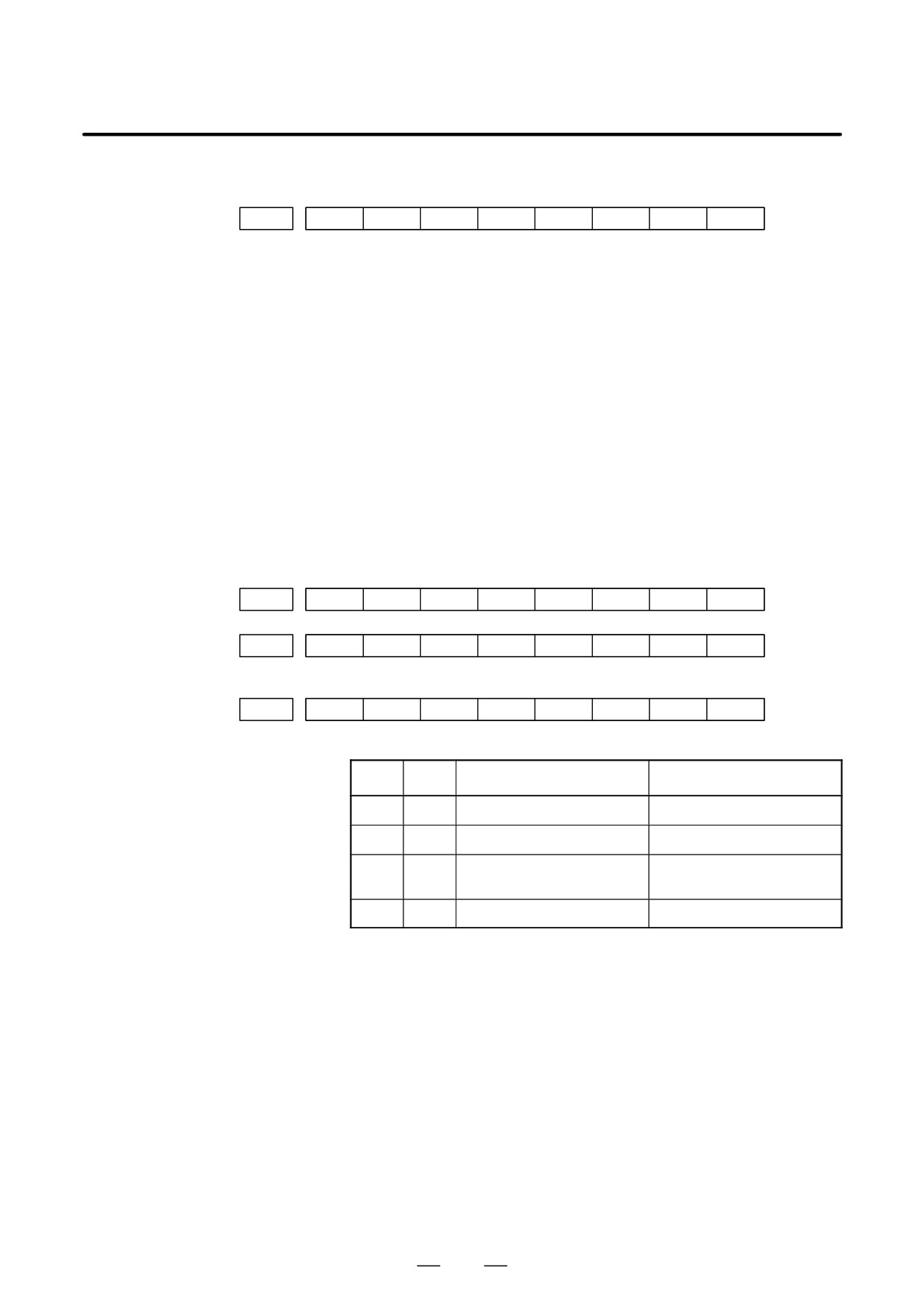
#7
#6
#5
#4
#3
#2
#1
#0
DGN
620
CFE
ERR
ERP
OPN
RDY
OPP
CLS
Indicates the internal status of the FSSBC2.
#0(CLS): Closed.
#1(OPP): Running OPEN protocol.
#2(RDY): Open and ready.
#3(OPN): Open.
#4(ERP): Running ERROR protocol.
#7(CFE): Encountered configuration error.
(The actual slave type does not match the one specified in the conversion
table.)
82
B-64115EN/02
1. DISPLAY AND OPERATION
#7
#6
#5
#4
#3
#2
#1
#0
DGN
621
XE3
XE2
XE1
XE0
ER3
ER2
ER1
ER0
Indicates the cause of an FSSBC2 error.
#0(ER0):
INFORMED ERROR
#1(ER1):
(RESERVE)
#2(ER2):
Master port disconnection
#3(ER3):
External EMG input
Indicates the cause of an FSSBC2 error resulting from a request from a slave.
#4(XE0):
(RESERVE)
#5(XE1):
Slave port disconnection
#6(XE2):
Master port disconnection
#7(XE3):
External EMG input
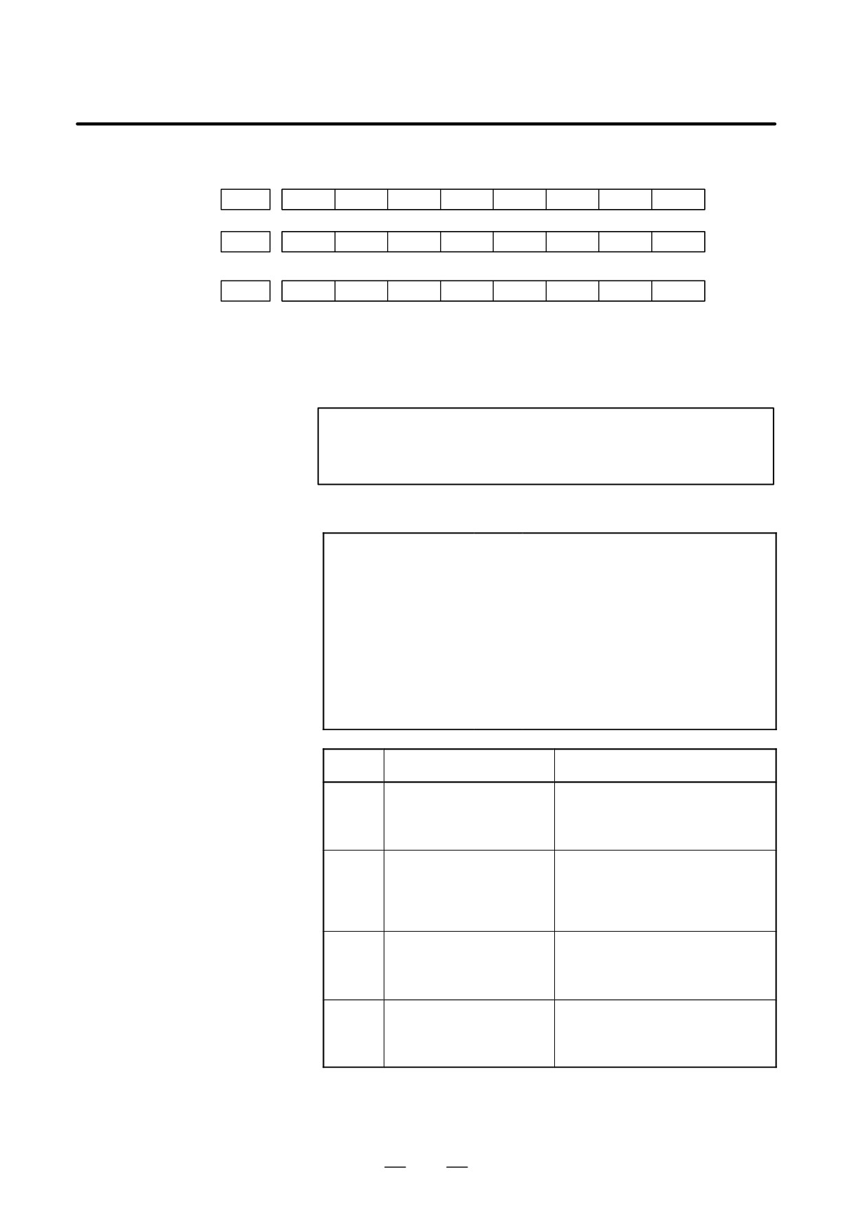
#7
#6
#5
#4
#3
#2
#1
#0
DGN
630
EXT
DUA
ST1
ST0
#7
#6
#5
#4
#3
#2
#1
#0
DGN
632
EXT
DUA
ST1
ST0
to
#7
#6
#5
#4
#3
#2
#1
#0
DGN
648
EXT
DUA
ST1
ST0
#0, #1(ST0, ST1):
Indicates the type code for an actually connected slave.
ST1
ST0
Type
Address
0
0
A
Servo amplifier
0
1
(B: RESERVE)
(Currently nonexistent)
1
0
C
Stand-alone type detector inter-
face unit
1
1
(RESERVE)
(Currently nonexistent)
#2(DUA):
0 : The slave of interest is not on the first axis of the two-axis amplifier.
1 : The slave of interest is on the first axis of the two-axis amplifier.
#3(EXT):
0 : The slave of interest does not exist.
1 : The slave of interest exists.
83
1. DISPLAY AND OPERATION
B-64115EN/02
#7
#6
#5
#4
#3
#2
#1
#0
DGN
631
DMA
TP1
TP0
HA2
HA1
HA0
#7
#6
#5
#4
#3
#2
#1
#0
DGN
633
DMA
TP1
TP0
HA2
HA1
HA0
to
#7
#6
#5
#4
#3
#2
#1
#0
DGN
649
DMA
TP1
TP0
HA2
HA1
HA0
#0, #1, #2(HA0, HA1, HA2):
Indicates the host LSI address specified as a DMA destination.
#3, #4 (TP0, TP1):
Indicates the type code of a specified slave.
(See the above descriptions about ST0 and ST1.)
#5(DMA):
Indicates a value determining whether to allow DMA to occur.
NOTE
A combination of parameter Nos. 630 and 631 corresponds
to one FSSB2 slave unit. Up to ten slave units are available.
Slave units and the associated diagnosis numbers
Slave unit 00
³
Diagnosis No. 630, No. 631
Slave unit 01
³
Diagnosis No. 632, No. 633
Slave unit 02
³
Diagnosis No. 634, No. 635
Slave unit 03
³
Diagnosis No. 636, No. 637
Slave unit 04
³
Diagnosis No. 638, No. 639
Slave unit 05
³
Diagnosis No. 640, No. 641
Slave unit 06
³
Diagnosis No. 642, No. 643
Slave unit 07
³
Diagnosis No. 644, No. 645
Slave unit 08
³
Diagnosis No. 646, No. 647
Slave unit 09
³
Diagnosis No. 648, No. 649
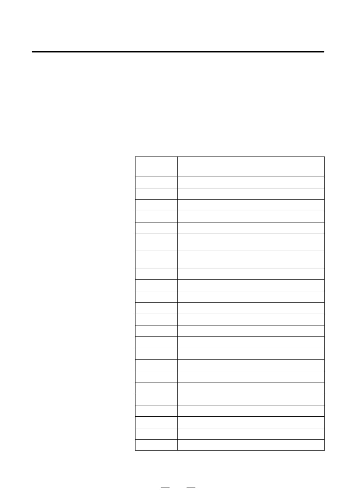
Number
Message
Contents
680
POWER ON CHECK SUM
Displays the parameter checksum at
power on.
The checksum is displayed only if CKS,
bit 0 of parameter No. 13730, is 1.
681
STANDARD CHECK SUM
Displays the checksum value when CKS,
bit 0 of parameter No. 13730, is set from
0 to 1.
The value is always displayed once you
create a reference checksum.
682
CALCULATION DATE
Displays the date when CKS, bit 0 of pa-
rameter No. 13730, is set to 0 to 1.
The value is always displayed once you
create a reference checksum.
683
CALCULATION TIME
Displays the time when CKS, bit 0 of pa-
rameter No. 13730, is set to 0 to 1.
The value is always displayed once you
create a reference checksum.
84
B-64115EN/02
1. DISPLAY AND OPERATION
The checksum is calculated not by adding all parameters together but by
excluding specific parameters. The parameters to be excluded are those
listed below.
<1> Parameters that enable input of settings
<2> Parameters that FANUC decided to be excluded in advance
<3> Parameters specified in parameters Nos. 13731 to 13750
<4> Parameters whose ranges are specified in parameters No. 13751 to
13770
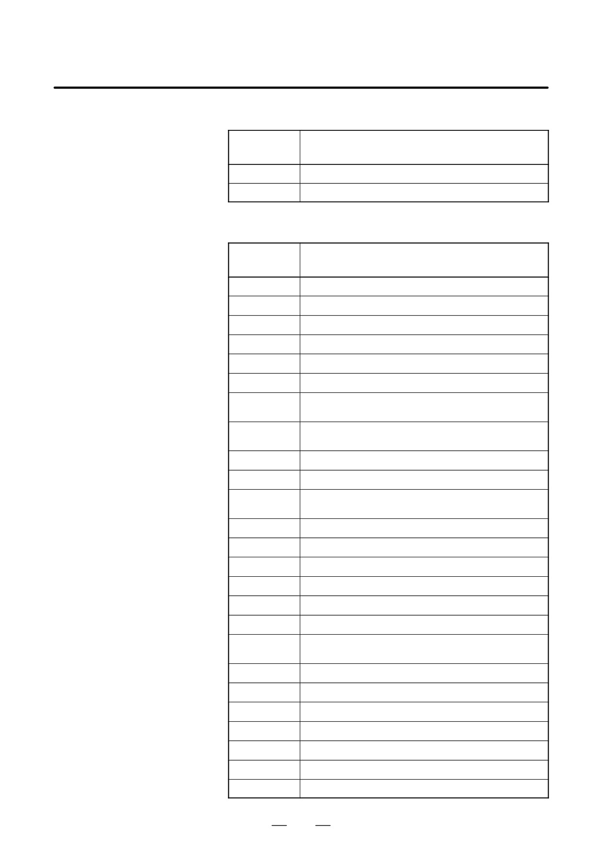
For information on parameters described in <2>, see the table below.
Nos. of the parameters not included in the checksum (M series)
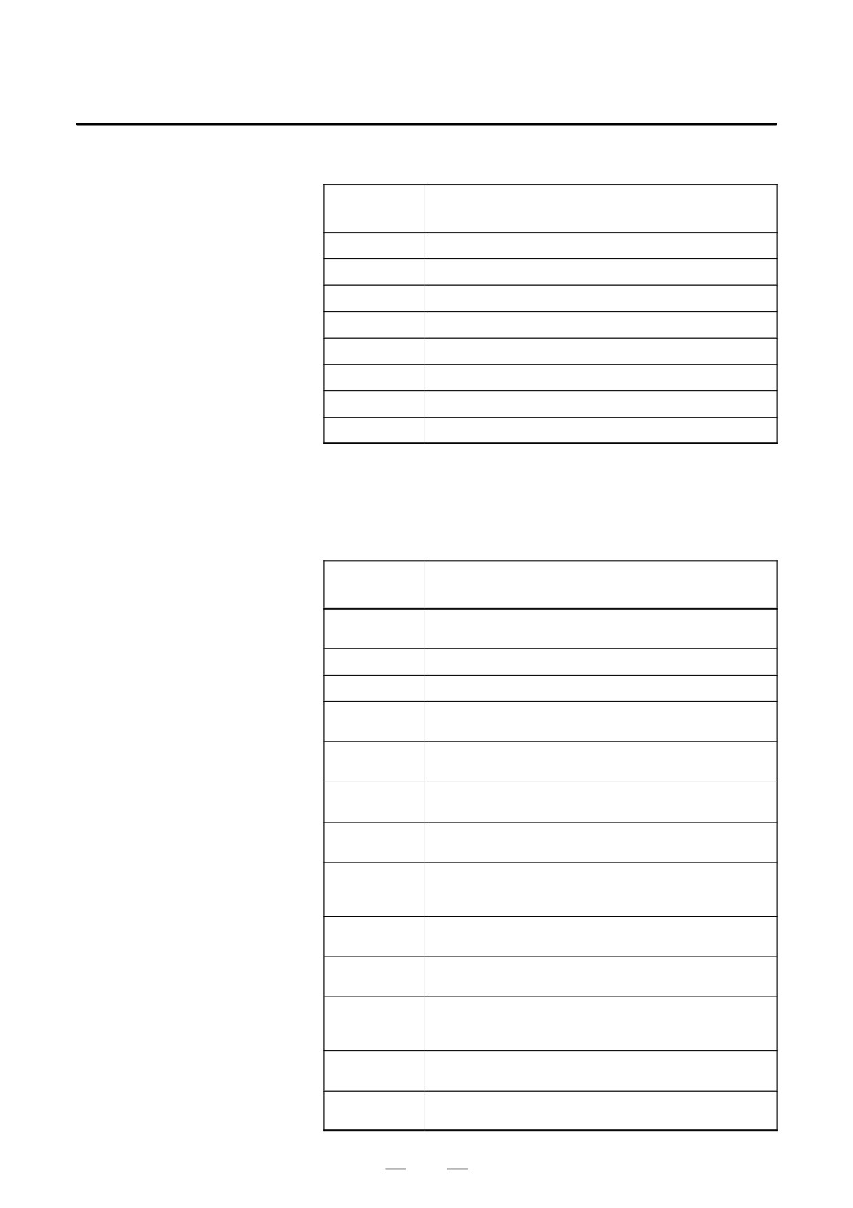
Parameter
Contents
number
1220 to 1226
Workpiece zero point offset value
1244
Coordinate of the floating reference position
1320 to 1321
Coordinates of the boundary of stored stroke check 1
1322 to 1323
Coordinates of the boundary of stored stroke check 2
1860 to 1861
Counter of the absolute-position detector
3120
Period of time from the time a wave diagnosis error occurs until
sampling stops
3271
LCD number when the power supply unit connected to two LCD
units is turned off
4911 to 4914
Spindle speed fluctuation detection
6350
Fine torque sensing
6360 to 6363
Fine torque sensing
6561 to 6575
VGA graphic color number
6581 to 6595
VGA character color number
6750
Accumulated power-on time
7220 to 7283
Names of the general-purpose switches on the operating panel
8182
Axis recomposition Display of the sync error amount
8370
Chopping axis number
8371 to 8374
Chopping reference point/upper dead point/lower dead point/velocity
8860 to 8861
Fault prediction level of the fault diagnosis function
8900
PWE
12801 to 12820
Signal symbol table number for selecting an operation history signal
12841 to 12860
Signal number for selecting an operation history signal
12881 to 12900
Mask pattern for selecting an operation history signal
12901 to 12925
Signal symbol table number for selecting an operation history signal
85
1. DISPLAY AND OPERATION
B-64115EN/02
Nos. of the parameters not included in the checksum (M series)
Parameter
Contents
number
12930 to 12955
Signal number for selecting an operation history signal
12961 to 12985
Mask pattern for selecting an operation history signal
Nos. of the parameters not included in the checksum (T series)
Parameter
Contents
number
1220 to 1226
Workpiece zero point offset value
1244
Coordinate of the floating reference position
1320 to 1321
Coordinates of the boundary of stored stroke check 1
1322 to 1323
Coordinates of the boundary of stored stroke check 2
1330 to 1348
Chuck/tailstock barrier
1860 to 1861
Counter of the absolute-position detector
3120
Period of time from the time a wave diagnosis error occurs until
sampling stops
3271
LCD number when the power supply unit connected to two LCD
units is turned off
4911 to 4914
Spindle speed fluctuation detection
5130
Amount of chamfering in the threading cycle (G96 or G92)
5132 to 5133
Dept of cut/clearance in the multiple repetitive canned cycle G71 or
G72
5135
Clearance on the X-axis in the multiple repetitive canned cycle G73
5136
Clearance on the Z-axis in the multiple repetitive canned cycle G73
5137
Number of divisions in the multiple repetitive canned cycle G73
5139
Amount of return in the multiple repetitive canned cycle G74 or G75
5140
Minimum depth of cut in the multiple repetitive canned cycle G76
5141
Finishing allowance in the multiple repetitive canned cycle G76
5142
Number of repetitions of the last finish in the multiple repetitive
canned cycle G76
5143
Tool nose angle in the multiple repetitive canned cycle G76
6350
Fine torque sensing
6360 to 6363
Fine torque sensing
6500
Graphic display
6561 to 6575
VGA graphic color number
6581 to 6595
VGA character color number
6750
Accumulated power-on time
86
B-64115EN/02
1. DISPLAY AND OPERATION
Nos. of the parameters not included in the checksum (T series)
Parameter
Contents
number
7220 to 7283
Names of the general-purpose switches on the operating panel
7625
Polygon turning speed
8182
Axis recomposition Display of the sync error amount
8860 to 8861
Fault prediction level of the fault diagnosis function
8900
PWE
12801 to 12820
Signal symbol table number for selecting an operation history signal
12841 to 12860
Signal number for selecting an operation history signal
12881 to 12900
Mask pattern for selecting an operation history signal
If you use the cutting condition selection function, the parameters listed
in the table below are also excluded.
Nos. of the parameters not included in the checksum (when the
cutting condition selection function is used)
Parameter
Contents
number
1432
Maximum cutting feedrate for each axis in advanced preview con-
trol/AI contour control/high-precision contour control mode
1730
Upper limit on the feedrate with the arc radius R
1731
Arc radius corresponding to the upper limit on the feedrate
1769
Time constant for cutting feedrate linear/bell-shaped acceleration/
deceleration for each axis
1770
Parameter 1 for setting the acceleration for linear acceleration/decel-
eration before interpolation
1771
Parameter 2 for setting the acceleration for linear acceleration/decel-
eration before interpolation
1772
Time constant for bell-shaped acceleration/deceleration with a
constant time of look-ahead acceleration before interpolation
1783
Per-axis permissible velocity difference for automatic corner decel-
eration with a velocity difference (for linear acceleration/deceleration
beforeinterpolation)
1785
Parameter for deciding on the permissible acceleration in velocity
determination with acceleration
1788
Permissible acceleration change for each axis in velocity control
with acceleration changes in jerk control
1789
Permissible acceleration change for each axis in velocity control
with acceleration changes in jerk control during continuous linear
interpolation
1790
Ratio of the jerk change time in smooth bell-shaped acceleration/
deceleration beforeinterpolation
8400
Parameter 1 for setting the acceleration for linear acceleration/decel-
eration before interpolation
87
1. DISPLAY AND OPERATION
B-64115EN/02
Nos. of the parameters not included in the checksum (when the
cutting condition selection function is used)
Parameter
Contents
number
8401
Parameter 2 for setting the acceleration for linear acceleration/decel-
eration before interpolation
8410
Permissible velocity difference in velocity determination with a cor-
ner velocity difference
8416
Look-ahead bell-shaped acceleration/deceleration beforeinterpola-
tion
8470
Parameter for deciding on the permissible acceleration in velocity
determination with acceleration
13634
Currently selected level in advanced preview control/AI contour
control
13680
Currently selected level when high-precision contour control is used
19522
Permissible acceleration change for each axis in velocity control
with acceleration changes in jerk control
19523
Permissible acceleration change for each axis in velocity control
with acceleration changes in jerk control during continuous linear
interpolation
19524
Ratio of the jerk change time in smooth bell-shaped acceleration/
deceleration beforeinterpolation
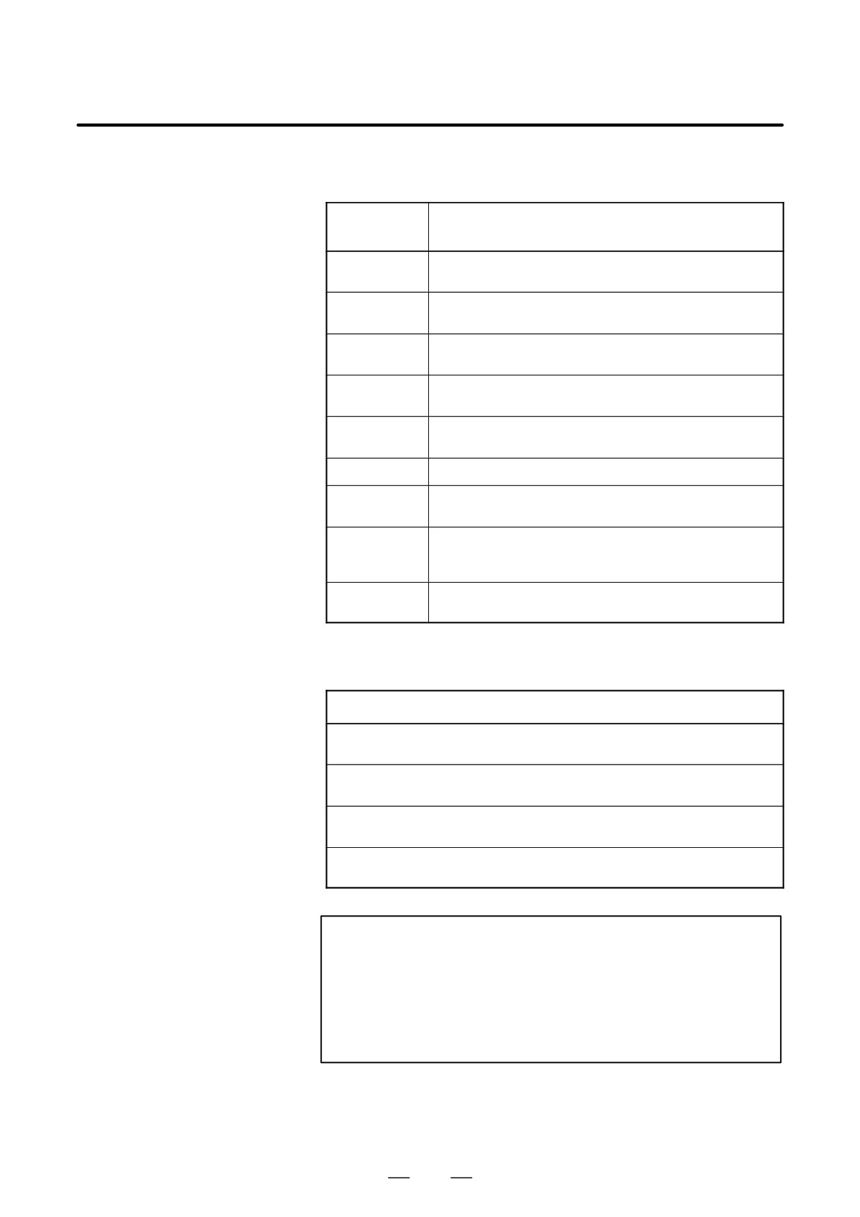
Nos. of the parameters not included in the checksum (when the
cutting condition selection function is used)
Parameter number
Number of the parameter set in parameter No. 13628 (parameter number corresponding
to arbitrary item 1 when advanced preview control/AI contour control is used)
Number of the parameter set in parameter No. 13629 (parameter number corresponding
to arbitrary item 2 when advanced preview control/AI contour control is used)
Number of the parameter set in parameter No. 13674 (parameter number corresponding
to arbitrary item 1 when high precision contour control is used)
Number of the parameter set in parameter No. 13675 (parameter number corresponding
to arbitrary item 2 when high precision contour control is used)
NOTE
1
If you do not use the cutting condition selection function,
these parameters are included in the checksum.
2
Parameters whose numbers are set in parameters Nos.
13628,
13629,
13674, and
13675 are excluded, but
parameters 13628, 13629, 13674, and 13675 themselves
are not excluded.
88
B-64115EN/02
1. DISPLAY AND OPERATION
D State of high-speed HRV
current control
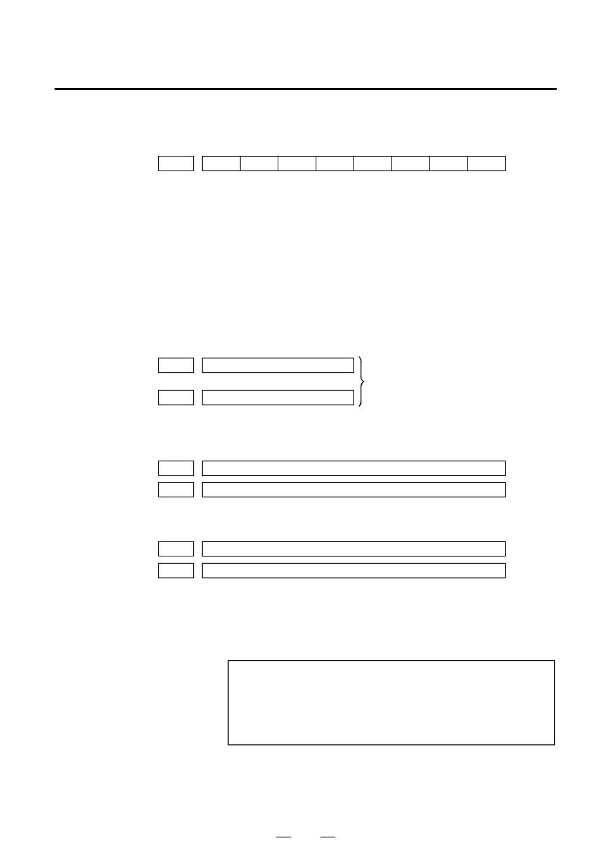
#7
#6
#5
#4
#3
#2
#1
#0
DGN
700
HOK
HON
[Data type]
Bit axis
The state of high-speed HRV current control is displayed.
HON:
The motor is controlled in the high-speed HRV current control mode.
HOK:
This bit is set to 1 when high-speed HRV current control is enabled.
High-speed HRV current control is enabled when the following
conditions are satisfied:
- Bit 0 (HR3) of parameter No. 2013 is set to 1.
- Servo software, servo modules, and servo amplifiers suitable for
high-speed HRV current control are used.
- When a separate detector interface unit is used, the separate detector
interface unit is suitable for high-speed HRV current control.
DGN
701
Not used in the FANUC Series
to
0i/0i Mate-MODEL C.
DGN
709
D Error and warning
statuses of the αi spindle
DGN
710
Error status of first spindle
DGN
711
Error status of second spindle
[Data type]
Word
DGN
712
Warning status of first spindle
DGN
713
Warning status of second spindle
[Data type]
Word
If an error (the yellow LED flashes and the error number appears) or
warning occurred in the αi spindle amplifier module (SPM), the number
is displayed on the diagnostic screen.
When there is no error or warning, ”0” is indicated.
NOTE
1
For spindles older than the αi spindle, this function is invalid.
2
When the system configuration of the spindle (even another
spindle) includes an additional spindle older than the αi
spindle, this function is invalid.
Refer to the FANUC SERVO MOTOR αi series Maintenance Manual
(B-65285EN) for errors on the αi spindle.
See Subsection 7.1.4, ”Warning Interface for the αi Spindle” in this
manual for warnings.
89
1. DISPLAY AND OPERATION
B-64115EN/02
1.9
CNC STATE DISPLAY
ACTUAL POSITION (ABSOLUTE)
O1000 N00010
X
217.940
Y
363.233
Z
0.000
PART COUNT
5
RUN TIME
0H15M CYCLE TIME
0H
0M38S
ACT.F
3000MM/M
S
0
T0000
MEM
STRT MTN
***
09:06:35
[ ABS ]
[ REL ]
[ ALL ]
[ HNDL ]
[ OPRT ]
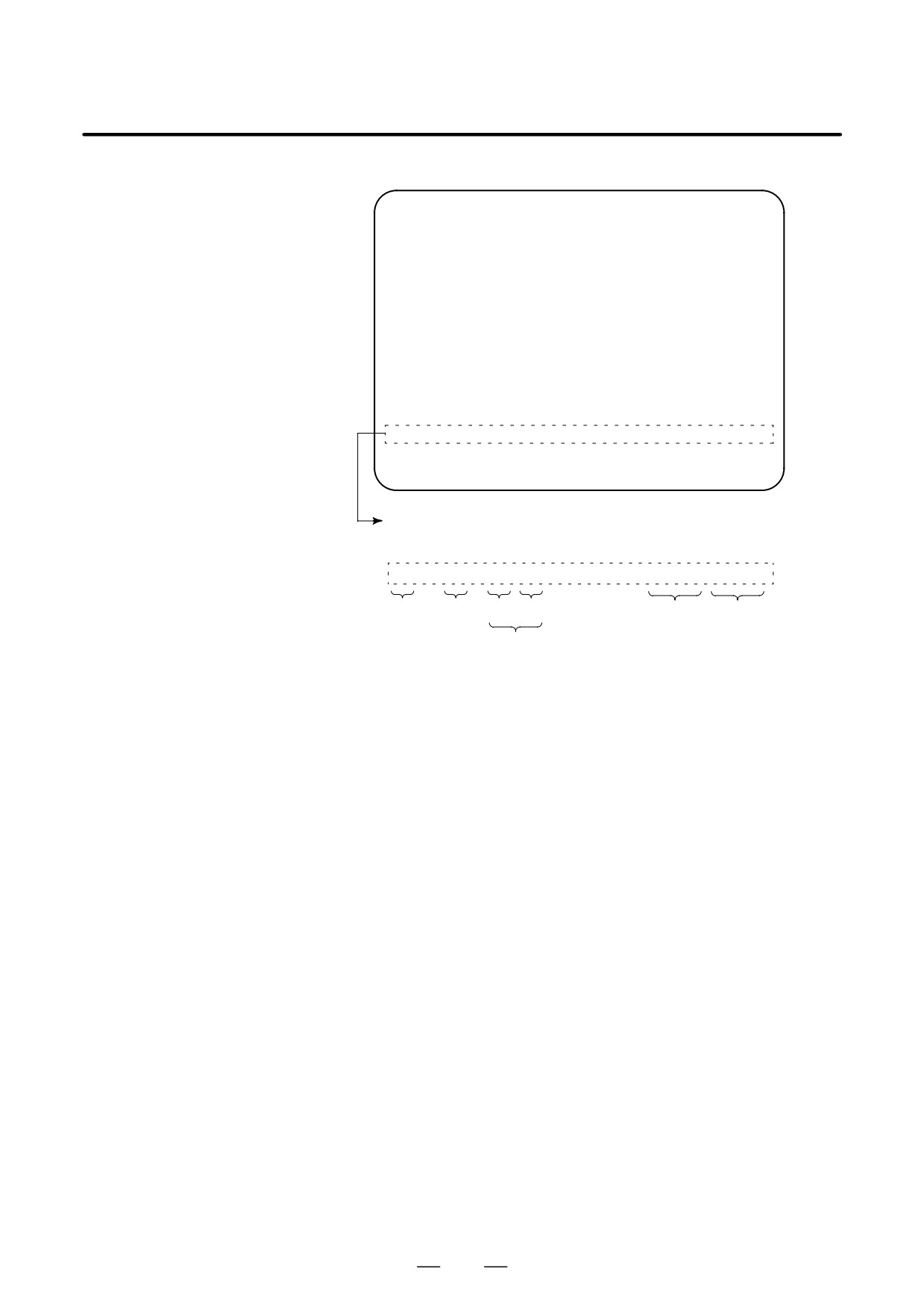
· Indicates the current status of the CNC.
· Display example and explanation
MEM
STRT MTN
***
09:06:35
(1)
(2)
(3)
(4)
(7)
(8)
(5)
(1) Mode selection status
MEM: Automatic operation (memory operation)
MDI: Manual data input/MDI operation
EDIT: Program editing
RMT: Remote operation
JOG: Jog feed
REF: Reference position return
INC: Incremental feed mode = step feed (if no manual pulse
generator is available)
HND: Manual handle feed mode
TJOG: Teaching in jog feed mode
THND:Teaching in handle feed mode
(2) Automatic operation status
STRT: Automatic operation has started (and program execution is
under way).
HOLD:Automatic operation has been suspended (execution of a
block has been discontinued, and automatic operation has
stopped).
STOP: Automatic operation has stopped (a block has been finished,
and automatic operation has stopped).
MSTR: The tool is returning or being repositioned when the tool
retract and return function is executed.
****: Other status (when the power is switched on, or automatic
operation has ended)
90
B-64115EN/02
1. DISPLAY AND OPERATION
(3) Automatic operation status
MTN: Program-specified axis movement is under way.
DWL: Program-specified dwell command (G04) is being executed.
***: Other status
(4) Auxiliary function status
FIN: The completion signal FIN for an auxiliary function is being
awaited.
***: Other status
(5) Emergency stop and reset status (displayed at the location of items
mentioned in (3) and (4))
--EMG--
: Emergency stop status
–RESET-: CNC reset status (The state in which the reset signal or
the MDI RESET key remains active.)
(6) Alarm status
ALM : An alarm condition has been detected.
BAT
: The lithium battery (CNC back-up battery) voltage is low
(the battery is to be replaced).
Blank: Other status
(7) Clock display: Hour:minute:second
(8) Program editing/running status
Input:
Data is being input.
Output:
Data is being output.
SRCH:
A data search is under way.
EDIT:
Editing such as insertion or modification is under way.
LSK:
Label skip enabled at data input (until valid information
is read).
AI APC: AI advanced preview control mode
AI CC:
AI contour control mode
Blank:
Editing is not under way.
91
1. DISPLAY AND OPERATION
B-64115EN/02
Tuning becomes easier by graphically displaying servo error amount and
1.10
torque command, etc. (Graphic option is required).
WAVEFORM
The following two types of waveform diagnosis functions are supported:
DIAGNOSTIC
FUNCTION
(1) One-shot type
The one-shot type waveform diagnosis function can graphically
display, as a waveform, any variation in those data items listed below.
The start of data sampling can be triggered by the rising or falling edge
of a machine signal. This function facilitates the adjustment of the
servo and spindle motors.
a. Error, pulse distribution amount, torque, speed, current, and
thermal simulation data for the servo motor of each axis
b. Composite speed for the first, second, and third axes
c. Spindle motor speed and load meter value
d. On/off state of a machine signal specified with a signal address
(2) Storage type
The storage type waveform diagnosis function enables the storing
of any variation in the data items listed below and, if a servo alarm
occurs, the graphical display (as a waveform) of the stored data. The
end of data sampling can be triggered by the rising or falling edge
of a machine signal. This function facilitates the estimation of
erroneous locations. Stored data can be output via the reader/punch
interface.
a. Error, pulse distribution amount, torque, speed, current, and
thermal simulation data for the servo motor for each axis
NOTE
1
To output stored waveform data, the optional reader/punch
interface must have been installed.
2
The waveform diagnosis function is enabled when bit 0
(SGD) of parameter No. 3112 is set to 1. Note, however, that
a graphics card is necessary to display waveforms.
1.10.1
Setting Parameters
#7
#6
#5
#4
#3
#2
#1
#0
DGN
3112
SGD
#0(SGD)
0 : Do not display servo waveform (usual graphic display).
1 : Displays servo waveform (usual graphic display function cannot be
used).
DGN
3120
Time between servo alarm and sampling stop (storage type)
[Data type] Word
[Unit of data] ms
[Valid data range] 1 to 32760
92
B-64115EN/02
1. DISPLAY AND OPERATION
DGN
3121
Selection of data of waveform diagnosis storage type
[Data type] Byte
The sixth-type sampling data of storage type of the waveform diagnosis
function is:
0 : Thermal simulation data
1 : Spindle load meter data of the first spindle
1.10.2
SYSTEM
1.Press the
key to display a system screen such as aparameter.
Waveform Diagnostic
2. Press the continuous menu key
several times, and the soft key
Parameter Screen
[W.DGNS] is displayed.
3. Press
[W.DGNS], then the parameter screen for the waveform
diagnosis is displayed.
Set the necessary data items. Position the cursor to the item to be set,
enter the corresponding data, then press
INPUT
. Data items for which
***** is displayed cannot be set. To assist in data setting, the frame on
the right side of the screen displays help information for that data to which
the cursor is positioned. Help information which cannot fit into a single
frame is split into several pages, which the user can scroll through using
PAGE
the page keys
and
PAGE
WAVE DIAGNOSE (PARAMETER)
O1234 N12345
GRP CONDITION 100
GRP CONDITION
(ONE-S TYPE)
SAMPLING TIME *****MS
0:START
TRIGGER *******
1:START&TRG
↑
2:START&TRG
↓
(MEMORY TYPE)
(CH-1)
(CH-2)
100: DATA OF
DATA NO.
11
22
MEMORY
UNIT
1000
10
1/3
SIGNAL
*******
*******
>
S
0
T0000
EDIT **** *** ***
08:20:52
[W.PRM]
[W.GRPH]
[ W.MEM ]
[
]
[
]
D Waveform diagnosis
(1) Display start condition
parameters (one-shot
0 : Starts data sampling upon the
[START] key being pressed,
type)
samples data for the specified period, then draws a waveform.
1 : Starts data sampling upon the detection of the first rising edge of
the trigger signal after the [START] key is pressed, samples data
for the specified period, then draws a waveform.
2 : Starts data sampling upon the detection of the first falling edge of
the trigger signal after the [START] key is pressed, samples data
for the specified period, then draws a waveform.
93
1. DISPLAY AND OPERATION
B-64115EN/02
(2) Sampling period: Set the period during which data will be sampled.
Valid data range: 10 to 32760
Units: ms
(3) Trigger: Set the PMC address and bit for the signal used to trigger the
start of data sampling, when 1 or 2 is set for the start condition.
Example) G0007.2: ST signal
(4) Data number: The table below lists the numbers of the data items for
which a waveform can be displayed (n = 1 to 4).
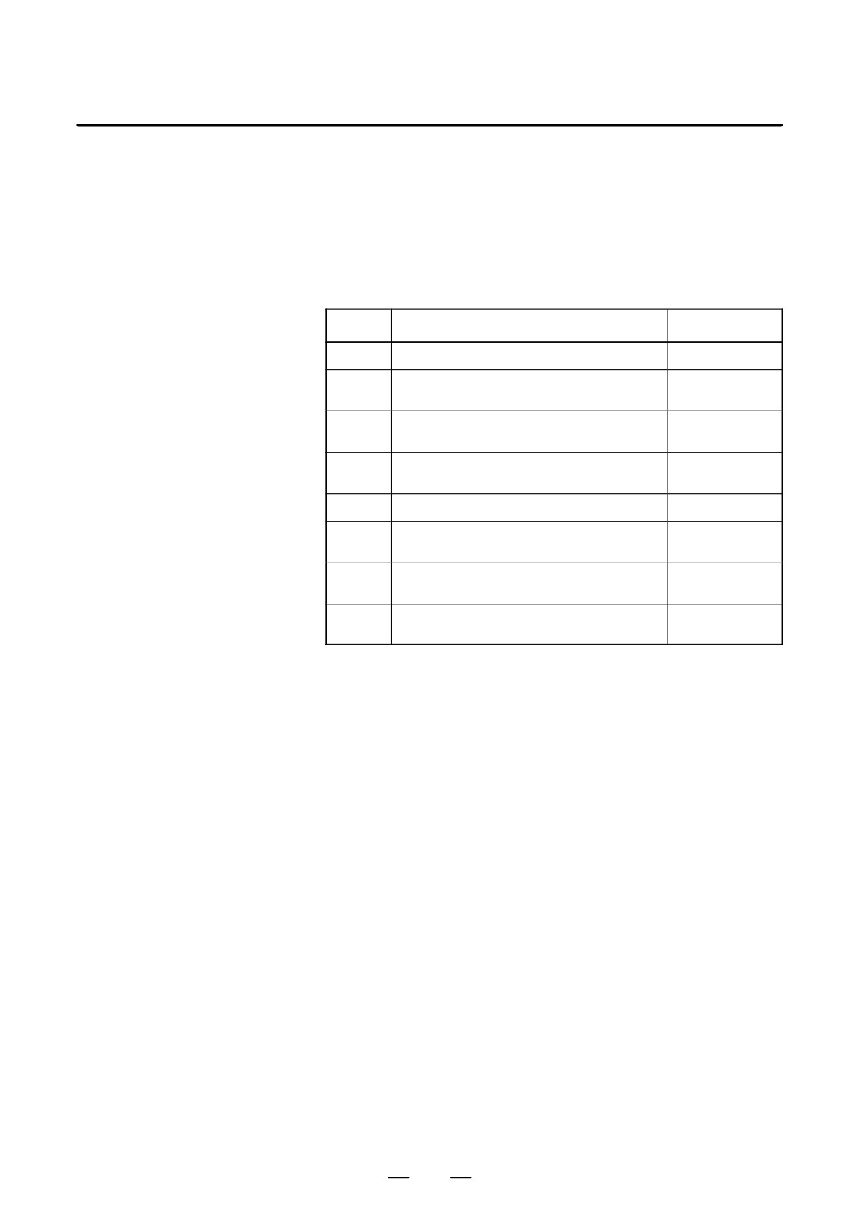
Data No.
Description
Units
00
Does not display a waveform.
-
0n
Servo error (8 ms) for the n-th axis (positional devi-
Pulses
ation)
(detection units)
1n
Pulse distribution for the n-th axis
Pulses
(move command)
(input increments)
2n
Torque for the n-th axis (actual current)
% (relative to maxi-
mum current)
3n
Servo error (2 ms) for the n-th axis (positional devi-
Pulses
ation)
(detection units)
5n
Actual speed for the n-th axis
min-1
6n
Command current for the n-th axis
% (relative to maxi-
mum current)
7n
Thermal simulation data for the n-th axis
% (OVC alarm ratio)
90
Composite speed for the first, second, and third axes
Pulses
(input increments)
99
On/off state of a machine signal specified with a sig-
None
nal address
10n
Actual spindle speed for the n-th axis
% (relative to maxi-
mum rotation
speed)
11n
Load meter for the n-th spindle
% (relative to maxi-
mum output)
161
Difference in position error calculated on the spindle
Pulses (detection
basis
unit)
(5) Data units: Weight of data when 1 is specified. The data units are
automatically specified for each data item and need not be set unless
the units must be changed for some reason.
[Valid data range] 1 to 1000
[Unit] 0.001
(6) Signal address: PMC address and bit number. Set in the same way as
that for trigger, when the data number is 99.
94
B-64115EN/02
1. DISPLAY AND OPERATION
D Waveform diagnosis
(1) Display start condition
parameters (storage
100 : Draws a waveform for the stored data.
type)
(2) Sampling period: Invalid
(3) Trigger: Invalid
(4) Data number: The table below lists the numbers of the data items for
which a waveform can be displayed (n = 1 to 4). Numbers for which
no data is stored cannot be specified.
Data No.
Description
Units
00
Does not display a waveform.
-
0n
Servo error (8 ms) for the n-th axis (positional devi-
Pulses
ation)
(detection units)
1n
Pulse distribution for the n-th axis (move command)
Pulses
(input increments)
2n
Torque for the n-th axis (actual current)
% (relative to maxi-
mum current)
5n
Actual speed for the n-th axis
min-1
6n
Command current for the n-th axis
% (relative to maxi-
mum current)
7n
Thermal simulation data for the n-th axis
% (OVC alarm ratio)
(when the parameter No.3121 is set to 0.)
111
Load meter for the n-th spindle
% (relative to maxi-
(when the parameter No.3121 is set to 1.)
mum output)
(5) Data units: Weight of data when 1 is specified. The data units are
automatically specified for each data item and need not be set unless
the units must be changed for some reason.
[Valid data range] 1 to 1000
[Unit] 0.001
(6) Signal address: Invalid
95
1. DISPLAY AND OPERATION
B-64115EN/02
1.10.3
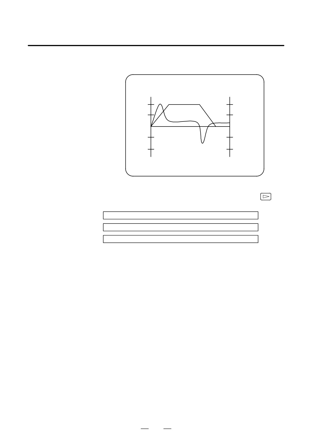
1. Press soft key [W.GRPH], then graph of waveform diagnosis is
displayed.
Graphic of Wave
Diagnosis Data
WAVE DIAGNOSE (GRAPHIC)
CH1
CH2
1.0
1.0
0.5
0.5
0
0
-0.5
-0.5
-1.0
–1.0
[START] [TIME³] [²TIME] [H-DOBL] [H-HALF]
2. Press soft key [(OPRT)], then the following soft keys are displayed.
The following three sets of soft keys are displayed by the
key.
[START] [TIME³] [²TIME] [H-DOBL] [H-DOBL]
[START] [CH-1°] [CH-1±] [V-DOBL] [V-HALF]
[START] [CH-2°] [CH-2±] [V-DOBL] [V-HALF]
1)
[START ]
: Starts Graphic data
2)
[TIME→]
: Shift the waveform of channel 1 and 2 rightward
3)
[←TIME]
: Shift the waveform of channel and 2 leftward
4)
[H-DOBL] : Double the time scale of the waveform of channel 1
and 2
5)
[H-HALF] : Half the time scale of the waveform of channel 1 and 2
6)
[H-DOBL] : Double the height of waveform of channel 1 and 2
7)
[V-HALF]
: Half the height of waveform of channel 1 and 2
8)
[CH-1↑]
: Shift the zero point of channel 1 upward
9)
[CH-1↓]
: Shift the zero point of channel 1 downward
10) [CH-2↑]
: Shift the zero point of channel 2 upward
11) [CH-2↓]
: Shift the zero point of channel 2 downward
D Drawing a waveform for
The one-shot type waveform diagnosis function draws a waveform for a
one-shot type waveform
specified data item in real time as the data is sampled. The sampled data,
diagnosis
however, is not stored and thus cannot be output later.
To sample data for one-shot type waveform diagnosis, press the
[START] key on the WAVE DIAGNOS. (GRAPHIC) screen. Then, data
is sampled when the specified start condition is satisfied. Data sampling
continues for the specified period.
96
B-64115EN/02
1. DISPLAY AND OPERATION
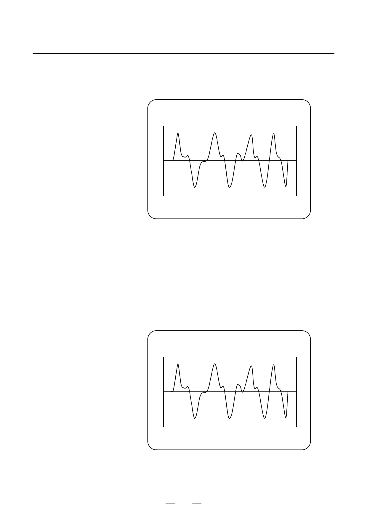
Pressing the [SATART] soft key starts data sampling. While sampling
is being performed, SAMPLING blinks at the top of the screen. Once data
sampling has been completed, a waveform is automatically displayed.
WAVE DIAGNOS. (GRAPHIC)
O1234 N12345
CH1
CH2
EDIT **** ******
[START] [TIME³] [²TIME] [H-DOBL] [H-HALF]
D Drawing a waveform for
To use storage type waveform diagnosis, set 100 for the display start
storage type waveform
condition. The maximum data width for storage type waveform diagnosis
diagnosis
is 32760 ms. Data must be sampled before starting drawing. The next
page explains sampling in detail.
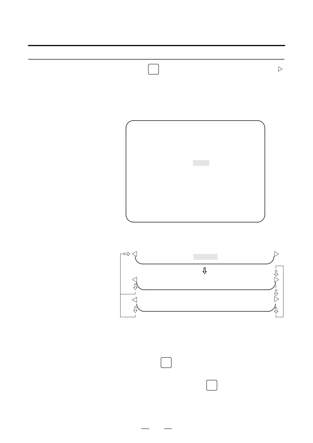
Pressing the [START] soft key loads stored data. While the data is being
loaded, SAMPLING blinks at the top of the screen. Once the data has
been loaded, a waveform is displayed. The date on which the data was
stored is displayed at the top left of the screen. If the [START] soft key
is pressed while data is being stored, storage is stopped and the waveform
for the data stored up to that point is displayed. The WAVE DIAGNOS.
(MEMORY) screen indicates whether data is being stored.
WAVE DIAGNOS. (GRAPHIC)
O1234 N12345
CH1 97/01/13
12:15:00
CH2
EDIT **** ******
[START] [TIME³] [²TIME] [H-DOBL] [H-HALF]
97
1. DISPLAY AND OPERATION
B-64115EN/02
1.10.4
(1) Press the
SYSTEM
function key. Pressing the menu continuation key [
]
Data Sampling for
displays the [W.DGNS] soft key. Press this soft key to display the
Storage Type
WAVE DIAGNOS. (PARAMETER) screen.
Waveform Diagnosis
(2) Press the [W.MEM] soft key to display the WAVE DIAGNOS.
(MEMORY) screen. The operation selection soft keys appear.
The configuration of the operation selection soft keys is as follows:
WAVE DIAGNOS. (MEMORY)
O1234 N12345
CONDITION:
100
TRIGGER: G0123.4
DATA KINDS
SAMPLING AXIS
POS ERROR
XYZA
MOTION CMD
XYZA
CURRENT (%)
XYZA
SPEED (RPM)
NONE
TORQUE CMD
NONE
HEAT SIMLT
XYZA
SMPL TIME :
2. 0SEC
DATE
: MEMORY
EDIT **** *** ***
08:20:52
[SELECT] [
] [
] [
] [START]
(3) The configuration of the operation selection soft keys is as
follows:
[W.PRM] [W.GRPH] [ W.MEM ] [
] [
]
Press
[SELECT] [
] [
] [
] [START]
[
] [
] [PUNCH] [
] [
]
Fig. 1.10.4 Soft keys
(4) Using the cursor, set the necessary data items. To set the sampling
axes, position the cursor to the data item to be set, enter the names of
the axes for which data will be sampled for that data item, then press
[SELECT] or
INPUT
. The axis names are displayed to the right of the
data items.
Example) XYZ + [SELECT] or
INPUT
(5) Once the sampling axes have been selected, the sampling period for
each axis is displayed. Subsequently pressing the [START] soft key
starts data sampling.
98
B-64115EN/02
1. DISPLAY AND OPERATION
CAUTION
1
Data items for which ***** is displayed cannot be set.
2
To change the sampling axes, enter new axis names then
press the [SELECT] soft key. Pressing the [SLELCT] soft
key without entering an axis name results in no sampling
axis being set.
3
If the sampling axes are changed during data sampling,
data sampling is stopped. In this case, press the [START]
soft key to restart data sampling for the new sampling axes.
4
Initially, no sampling axis is set.
5
When the sixth-type sampling data is spindle load meter
data (parameter No. 3121 = 1), set the axis name S.
D Storage data parameters
(1) Storage stop condition
100: Stops data storage upon the issue of a servo alarm.
101: Stops data storage upon the issue of a servo alarm or the
detection of the rising edge of the trigger signal.
102: Stops data storage upon the issue of a servo alarm or the
detection of the falling edge of the trigger signal.
The maximum stored data width is 32760 ms. If the storage stop
condition is not satisfied within 32760 ms, data is overwritten, starting
with the oldest data.
Parameter No. 3120 can be used to delay data storage being stopped
by a specified period (ms), after the issue of a servo alarm.
(2) Trigger: Set the PMC address and bit for the signal used to trigger the
stopping of data storage, when 101 or 102 is set for the stop condition.
Example) G0007.2: ST signal
(3) Data type: The following table lists the types of data for which a
waveform can be displayed.
Data type
Description
Units
POS ERROR
Servo error (8 ms) for the n-th axis
Pulses
(detection units)
MOTION CMD
Pulse distribution for the n-th axis
Pulses
(input increments)
CURRENT (%)
Torque for the n-th axis
% (relative to maxi-
mum current)
SPEED (RPM)
Actual speed for the n-th axis
min-1
TORQUE CMD
Command current for the n-th axis
% (relative to maxi-
mum current)
HEAT SIMLT
Thermal simulation data for the n-th axis
%
(when the parameter No.3121 is set to 0.)
(OVC alarm ratio)
LOAD METER
Load meter for the n-th spindle
% (relative to maxi-
(when the parameter No.3121 is set to 1.)
mum output)
99