FANUC Series 0i-MODEL C, Series 0i Mate-MODEL C. MAINTENANCE MANUAL - page 3
1. DISPLAY AND OPERATION
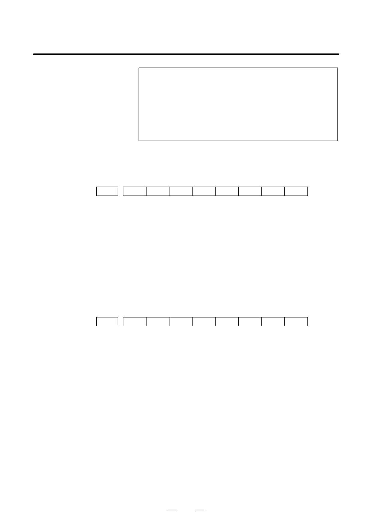
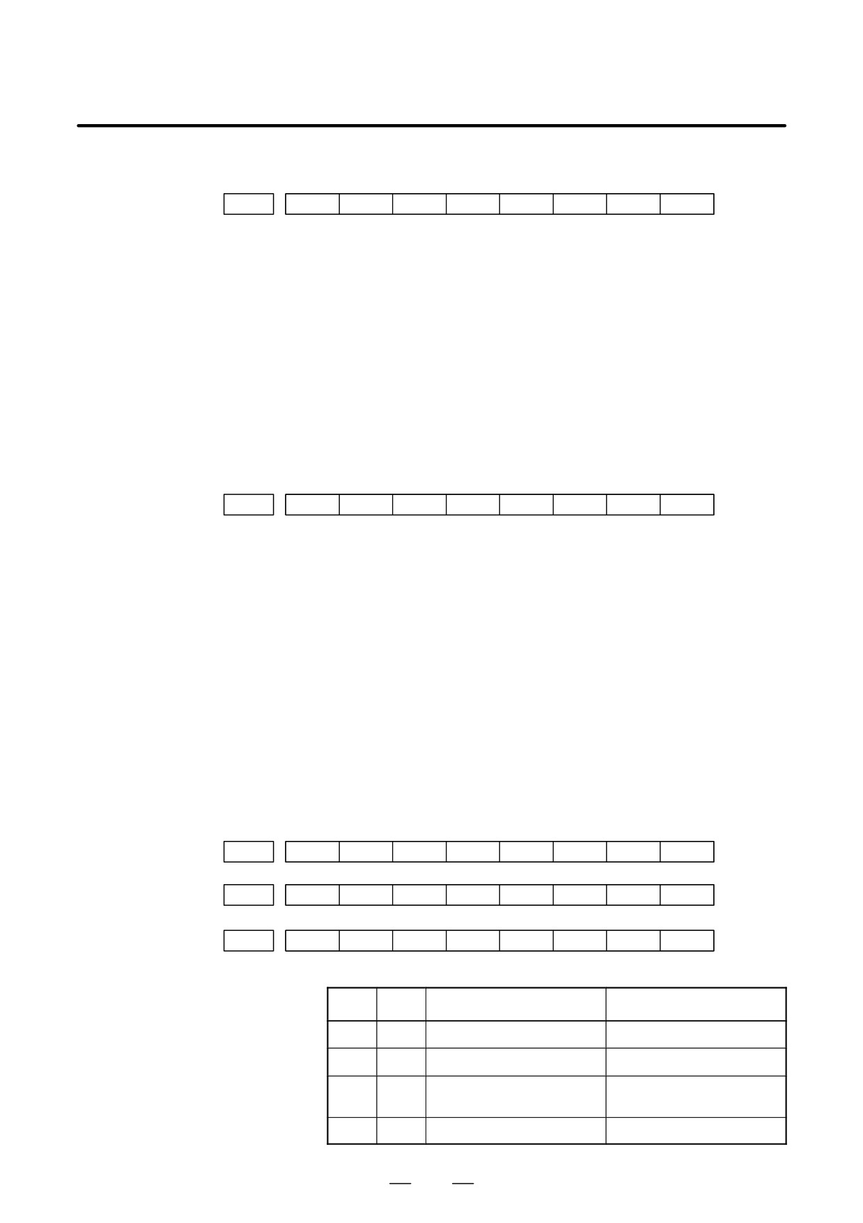
B-64115EN/02
This function displays the key and signal operations performed by the
1.6
operator upon the occurrence of a fault or the output of an alarm, together
OPERATION
with the corresponding alarms.
HISTORY
This function records the following data:
(1) MDI key operations performed by the operator
(2) Status changes (ON/OFF) of input and output signals (selected signals
only)
(3) Details of alarms
(4) Time stamp (date and time)
1.6.1
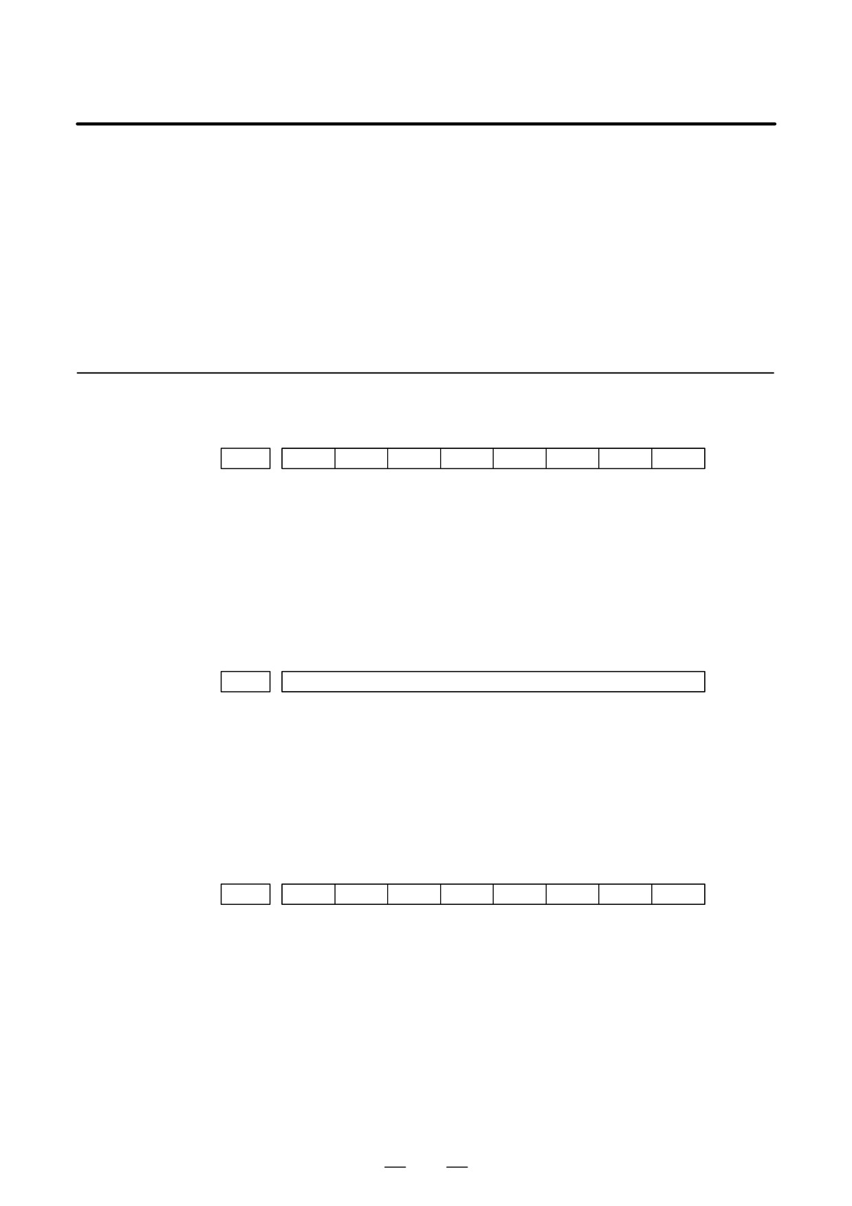
Parameter Setting
#7
#6
#5
#4
#3
#2
#1
#0
3106
OHS
OPH
[Data type]
Bit
OPH
The operation history screen is:
0 : Not displayed.
1 : Displayed.
OHS
The operation history is:
0 : Sampled.
1 : Not sampled.
3122
Interval at which the clock time is recorded in the operation history
[Data type]
Word
[Units of data]
Minutes
[Valid data range]
0 to 1439
The clock time is recorded to the operation history at specified intervals.
If zero is set as the interval, ten minutes is assumed. The time is recorded
only when data is recorded within the corresponding interval.
#7
#6
#5
#4
#3
#2
#1
#0
3206
PHS
[Data type]
Bit
PHS
Setting and display on the operation history signal selection screen and
the parameters (No. 12801 through No. 128900) are:
0 : Not linked.
1 : Linked.
40
B-64115EN/02
1. DISPLAY AND OPERATION
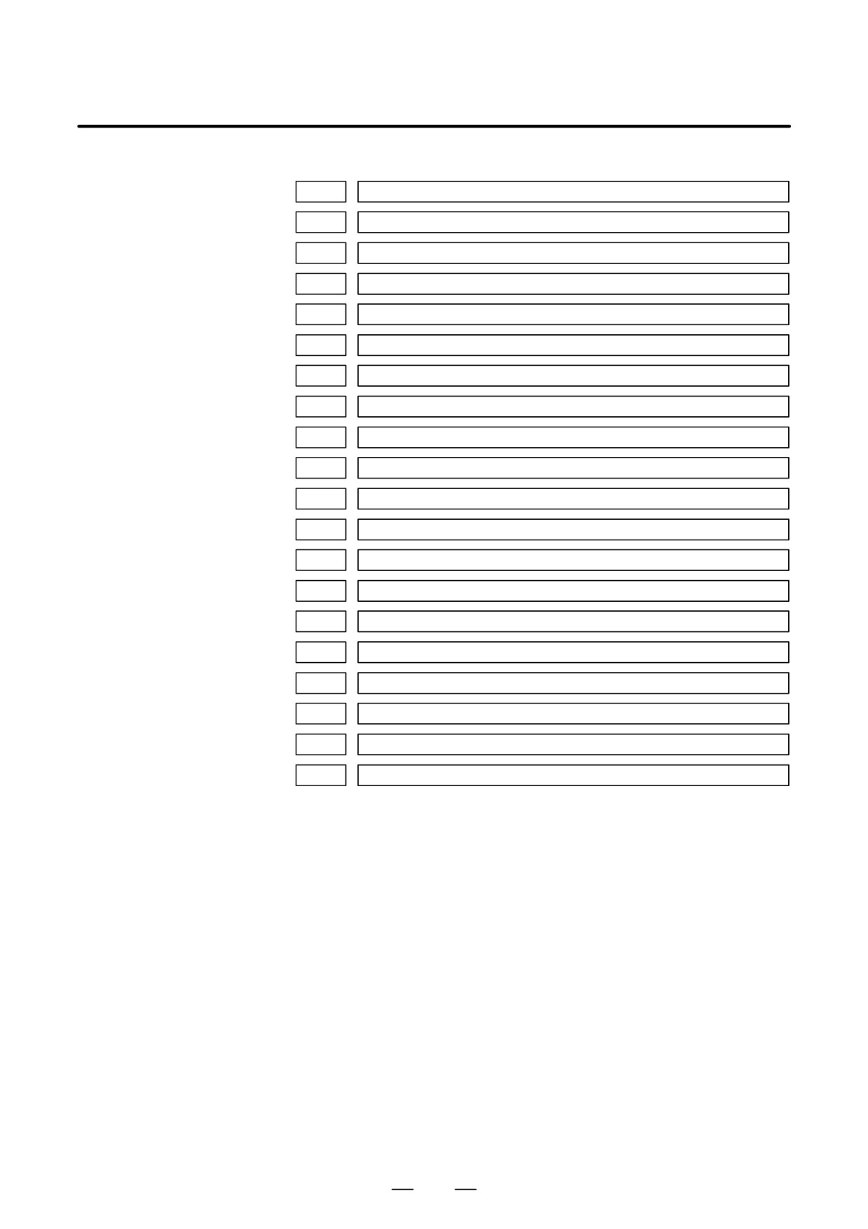
12801
Number of a signal symbol table for selecting an operation history signal (01)
12802
Number of a signal symbol table for selecting an operation history signal (02)
12803
Number of a signal symbol table for selecting an operation history signal (03)
12804
Number of a signal symbol table for selecting an operation history signal (04)
12805
Number of a signal symbol table for selecting an operation history signal (05)
12806
Number of a signal symbol table for selecting an operation history signal (06)
12807
Number of a signal symbol table for selecting an operation history signal (07)
12808
Number of a signal symbol table for selecting an operation history signal (08)
12809
Number of a signal symbol table for selecting an operation history signal (09)
12810
Number of a signal symbol table for selecting an operation history signal (10)
12811
Number of a signal symbol table for selecting an operation history signal (11)
12812
Number of a signal symbol table for selecting an operation history signal (12)
12813
Number of a signal symbol table for selecting an operation history signal (13)
12814
Number of a signal symbol table for selecting an operation history signal (14)
12815
Number of a signal symbol table for selecting an operation history signal (15)
12816
Number of a signal symbol table for selecting an operation history signal (16)
12817
Number of a signal symbol table for selecting an operation history signal (17)
12818
Number of a signal symbol table for selecting an operation history signal (18)
12819
Number of a signal symbol table for selecting an operation history signal (19)
12820
Number of a signal symbol table for selecting an operation history signal (20)
[Data type] Byte
[Valid data range] 1 to 10
Set the number of a symbol table including a signal of which operation
history is to be recorded for operation history channel (01) to (20) as
follows:
1
: G0
to G255
3
: F0
to F255
5
: Y0
to Y127
6
: X0
to X127
41
1. DISPLAY AND OPERATION
B-64115EN/02
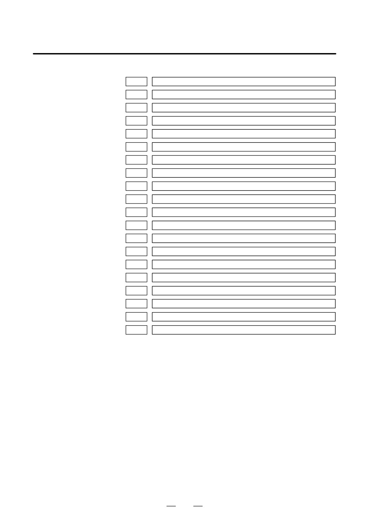
12841
Number of a signal selected as an operation history signal (01)
12842
Number of a signal selected as an operation history signal (02)
12843
Number of a signal selected as an operation history signal (03)
12844
Number of a signal selected as an operation history signal (04)
12845
Number of a signal selected as an operation history signal (05)
12846
Number of a signal selected as an operation history signal (06)
12847
Number of a signal selected as an operation history signal (07)
12848
Number of a signal selected as an operation history signal (08)
12849
Number of a signal selected as an operation history signal (09)
12850
Number of a signal selected as an operation history signal (10)
12851
Number of a signal selected as an operation history signal (11)
12852
Number of a signal selected as an operation history signal (12)
12853
Number of a signal selected as an operation history signal (13)
12854
Number of a signal selected as an operation history signal (14)
12855
Number of a signal selected as an operation history signal (15)
12856
Number of a signal selected as an operation history signal (16)
12857
Number of a signal selected as an operation history signal (17)
12858
Number of a signal selected as an operation history signal (18)
12859
Number of a signal selected as an operation history signal (19)
12860
Number of a signal selected as an operation history signal (20)
[Data type] Word
[Valid data range] 0 to 255 (Decimal number)
Set the number of a signal of which operation history is to be recorded for
operation history channel (01) to (20) with a value between 0 and 255.
42
B-64115EN/02
1. DISPLAY AND OPERATION
#7
#6
#5
#4
#3
#2
#1
#0
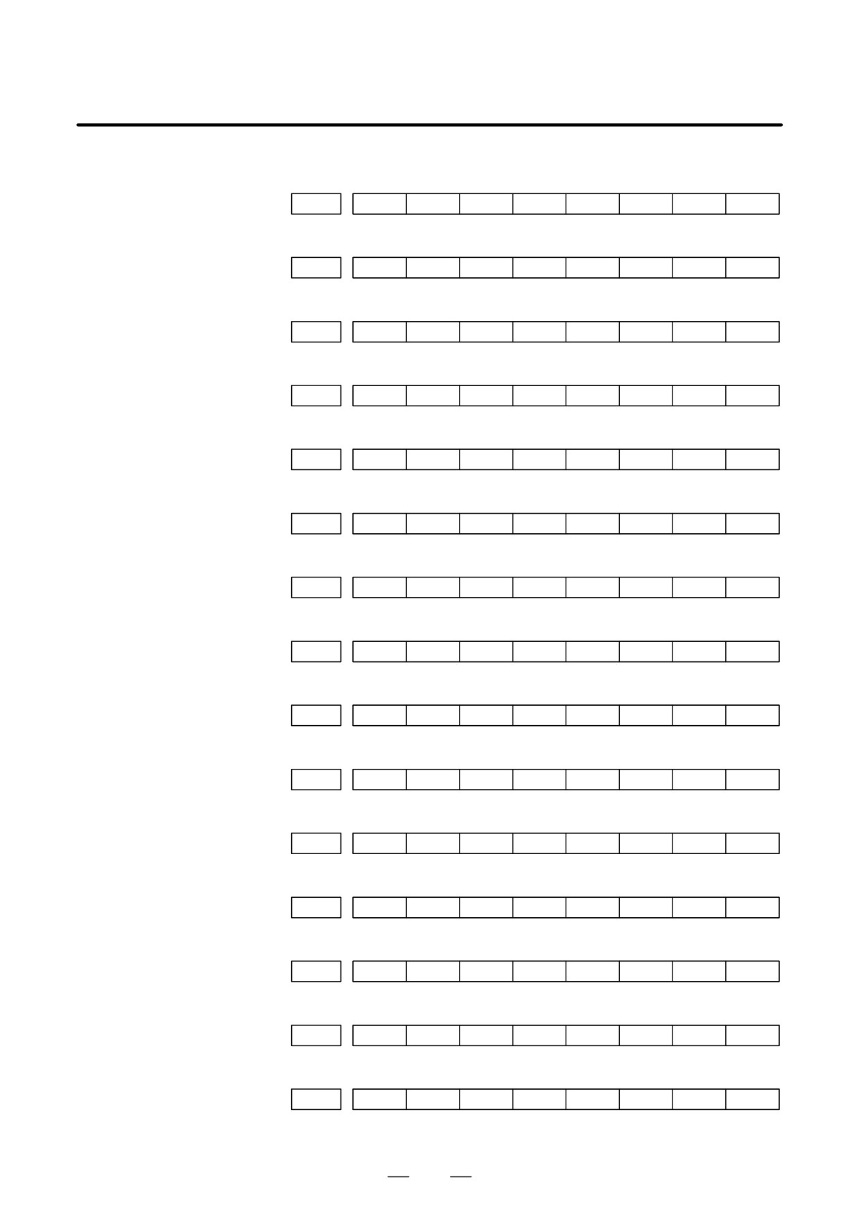
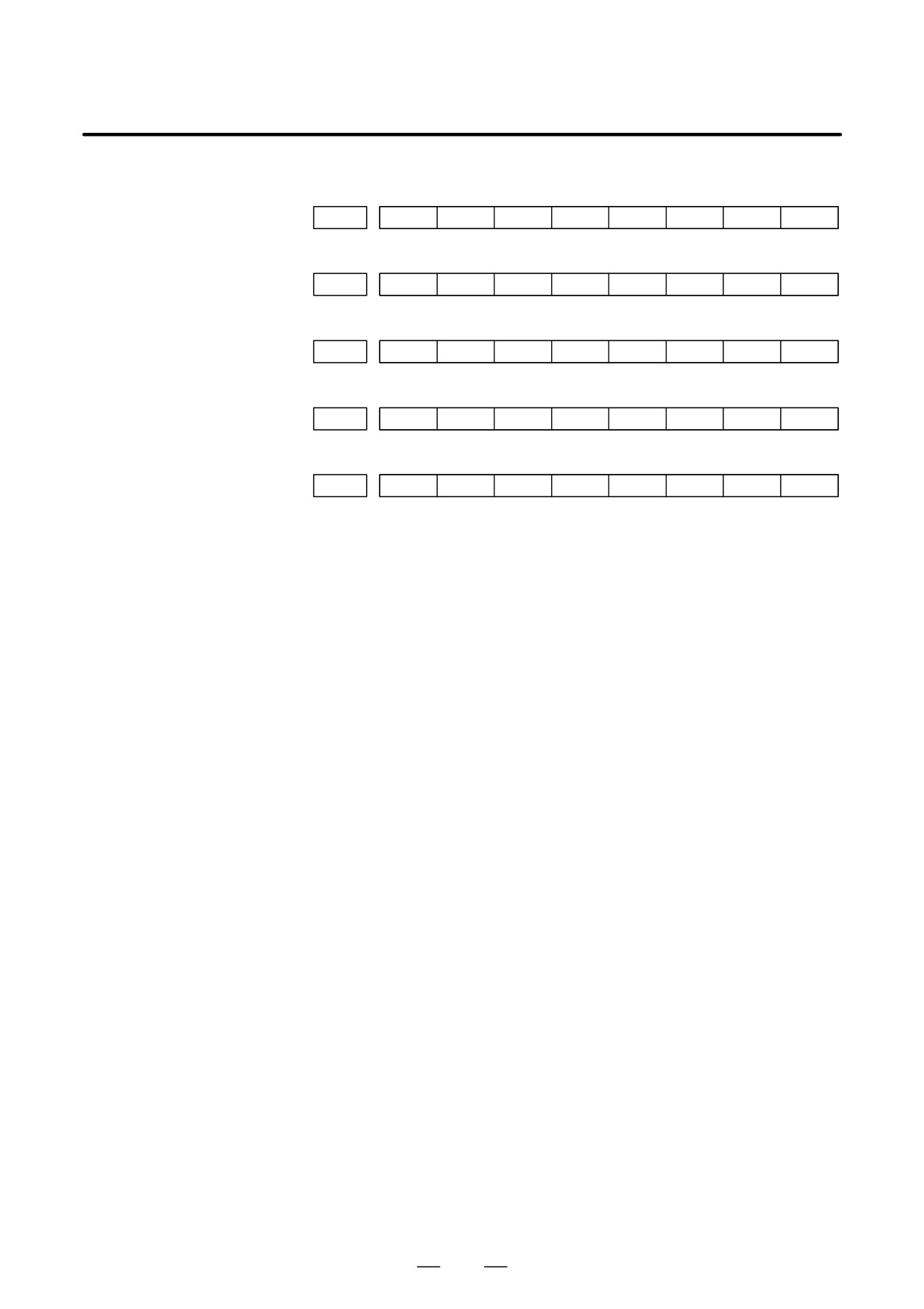
12881
RB7
RB6
RB5
RB4
RB3
RB2
RB1
RB0
History record bit settings for an operation history signal (01)
#7
#6
#5
#4
#3
#2
#1
#0
12882
RB7
RB6
RB5
RB4
RB3
RB2
RB1
RB0
History record bit settings for an operation history signal (02)
#7
#6
#5
#4
#3
#2
#1
#0
12883
RB7
RB6
RB5
RB4
RB3
RB2
RB1
RB0
History record bit settings for an operation history signal (03)
#7
#6
#5
#4
#3
#2
#1
#0
12884
RB7
RB6
RB5
RB4
RB3
RB2
RB1
RB0
History record bit settings for an operation history signal (04)
#7
#6
#5
#4
#3
#2
#1
#0
12885
RB7
RB6
RB5
RB4
RB3
RB2
RB1
RB0
History record bit settings for an operation history signal (05)
#7
#6
#5
#4
#3
#2
#1
#0
12886
RB7
RB6
RB5
RB4
RB3
RB2
RB1
RB0
History record bit settings for an operation history signal (06)
#7
#6
#5
#4
#3
#2
#1
#0
12887
RB7
RB6
RB5
RB4
RB3
RB2
RB1
RB0
History record bit settings for an operation history signal (07)
#7
#6
#5
#4
#3
#2
#1
#0
12888
RB7
RB6
RB5
RB4
RB3
RB2
RB1
RB0
History record bit settings for an operation history signal (08)
#7
#6
#5
#4
#3
#2
#1
#0
12889
RB7
RB6
RB5
RB4
RB3
RB2
RB1
RB0
History record bit settings for an operation history signal (09)
#7
#6
#5
#4
#3
#2
#1
#0
12890
RB7
RB6
RB5
RB4
RB3
RB2
RB1
RB0
History record bit settings for an operation history signal (10)
#7
#6
#5
#4
#3
#2
#1
#0
12891
RB7
RB6
RB5
RB4
RB3
RB2
RB1
RB0
History record bit settings for an operation history signal (11)
#7
#6
#5
#4
#3
#2
#1
#0
12892
RB7
RB6
RB5
RB4
RB3
RB2
RB1
RB0
History record bit settings for an operation history signal (12)
#7
#6
#5
#4
#3
#2
#1
#0
12893
RB7
RB6
RB5
RB4
RB3
RB2
RB1
RB0
History record bit settings for an operation history signal (13)
#7
#6
#5
#4
#3
#2
#1
#0
12894
RB7
RB6
RB5
RB4
RB3
RB2
RB1
RB0
History record bit settings for an operation history signal (14)
#7
#6
#5
#4
#3
#2
#1
#0
12895
RB7
RB6
RB5
RB4
RB3
RB2
RB1
RB0
History record bit settings for an operation history signal (15)
43
1. DISPLAY AND OPERATION
B-64115EN/02
#7
#6
#5
#4
#3
#2
#1
#0
12896
RB7
RB6
RB5
RB4
RB3
RB2
RB1
RB0
History record bit settings for an operation history signal (16)
#7
#6
#5
#4
#3
#2
#1
#0
12897
RB7
RB6
RB5
RB4
RB3
RB2
RB1
RB0
History record bit settings for an operation history signal (17)
#7
#6
#5
#4
#3
#2
#1
#0
12898
RB7
RB6
RB5
RB4
RB3
RB2
RB1
RB0
History record bit settings for an operation history signal (18)
#7
#6
#5
#4
#3
#2
#1
#0
12899
RB7
RB6
RB5
RB4
RB3
RB2
RB1
RB0
History record bit settings for an operation history signal (19)
#7
#6
#5
#4
#3
#2
#1
#0
12900
RB7
RB6
RB5
RB4
RB3
RB2
RB1
RB0
History record bit settings for an operation history signal (20)
[Data type] Bit
RB7 to RB0
For the signal set in channel (01) to (20), of which operation history is to
be recorded, the history of each bit is:
0 : Not recorded. (The history of this bit is not recorded.)
1 : Recorded. (The history of this bit is recorded.)
44
B-64115EN/02
1. DISPLAY AND OPERATION
1.6.2
Screen Display
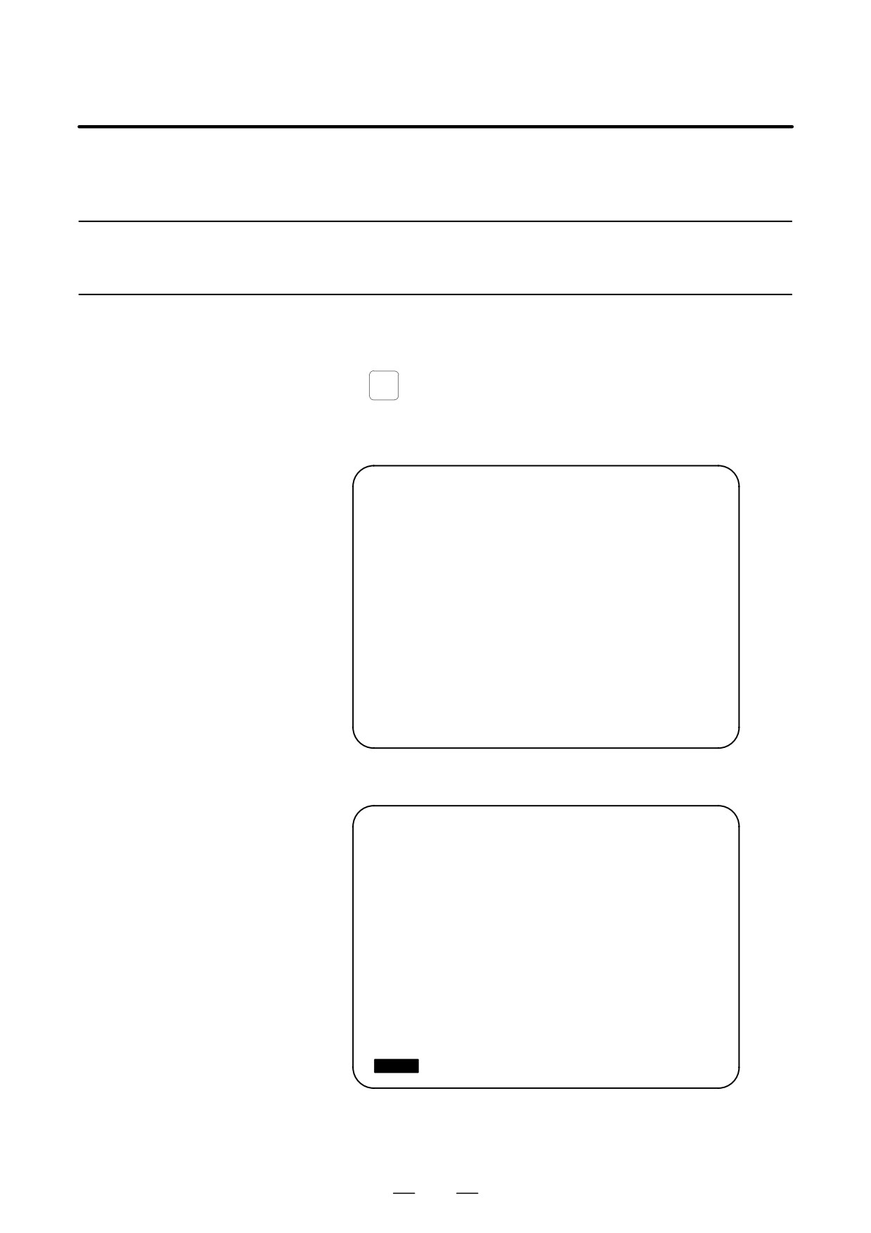
D Displaying the operation
SYSTEM
(1) Press the
function key.
history
(2) Press the continue menu key [
]. The [OPEHIS] (OPERATION
HISTORY) soft key are displayed.
(3) Press the [OPEHIS] soft key twice. The operation history screen is
displayed.
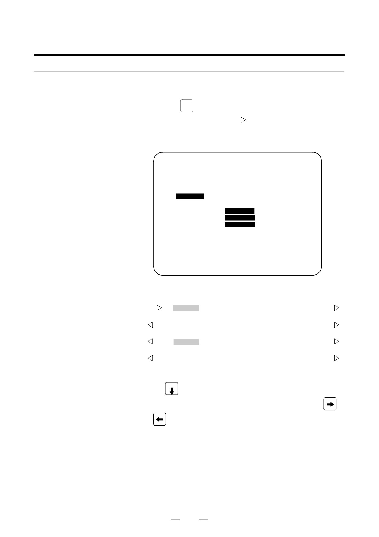
OPERATION HISTORY
O1234 N12345
Page : 123
No. DATA
No. DATA
No. DATA
01 01/06/03
11 F0000.7↑
21 F0001.0↓
02 08:40:00
12 F0000.5↑
22 <POS>
03 <DELETE>
13 F0001.0↑
23 <PROG>
04 F0000.6↑
14 F0000.5↓
24 <RESET>
05 MEM
15 P/S0010
25 EDIT
06 G0009.0↑
16 02/06/03
26 O
07 G0009.1↑
17 09:27:49
27 1
08 G0009.2↑
18 <PROG>
28 2
09 ST↑
19 <RESET>
29 3
10 ST↓
20 F0000.7↓
30 4
EDIT ****
***
***
08:20:52
[ TOP
][ BOTTOM ][
][
][PG.SRH]
On the operation history screen, the soft keys are configured as shown
below:
⇒ [
]
[ PARAM ]
[DGNOS]
[PMC]
[SYSTEM] [(OPE)] [
]
ãpush
[
]
[W.DGNS] [
] [
]
[OPEHIS]
[(OPE)] [
]
ã push
[
]
[ OPEHIS ] [SG-SEL]
[
]
[
]
[(OPE)] [
]
ãpush
[
]
[ TOP
]
[BOTTOM] [
]
[
]
[PG.SRH] [
]
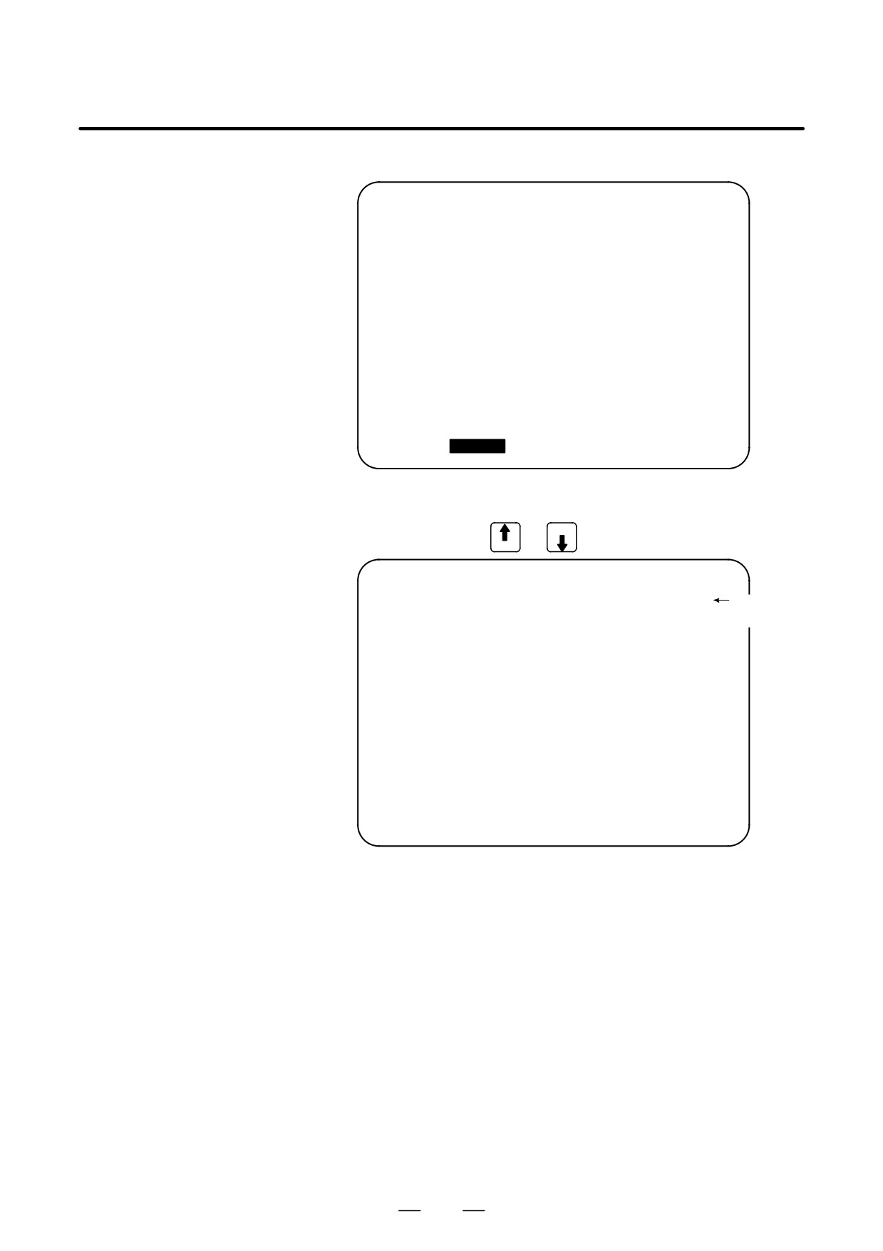
(4) To display the next part of the operation history, press the page down
key PAGE
. The next page is displayed.
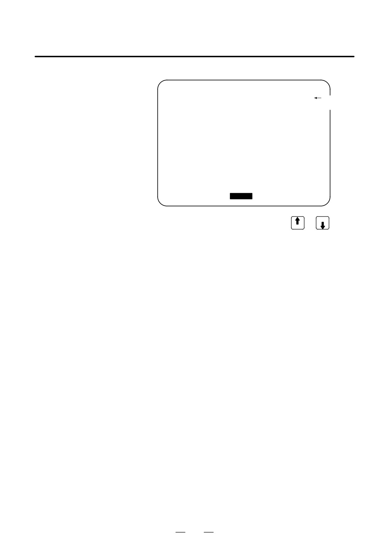
To display the interface between two pages, press cursor key
or
. The screen is scrolled by one row. On a 14-inch CRT screen,
pressing the cursor key scrolls the screen by half a page.
These soft keys can also be used:
1) Pressing the [TOP] soft key displays the first page (oldest data).
2) Pressing the [BOTTOM] soft key displays the last page (latest
data).
3) Pressing the [PG.SRH] soft key displays a specified page.
Example) By entering 50 then pressing the [PG.SRH] key, page 50 is
displayed.
45

1. DISPLAY AND OPERATION
B-64115EN/02
Data displayed on the operation history screen
(1) MDI keys
Address and numeric keys are displayed after a single space.
Soft keys are displayed in square brackets ([]).
Other keys (RESET/INPUT, for example) are displayed in angle
brackets (<>).
A key pressed at power-on is displayed in reverse video.
1) Function key: <POS>, <PROG>, <OFFSET>, etc.
2) Address/numeric key: A to Z, 0 to 9, ; (EOB), +, -, (, etc.
3) Page/cursor key: <PAGE↑>, <CUR↓>, <CUR←>
4) Soft key:
[SF1], [SF2], etc.
5) Other key: <RESET>, <CAN>, etc.
6) Key pressed at power-on:
<RESET>
(2) Input and output signals
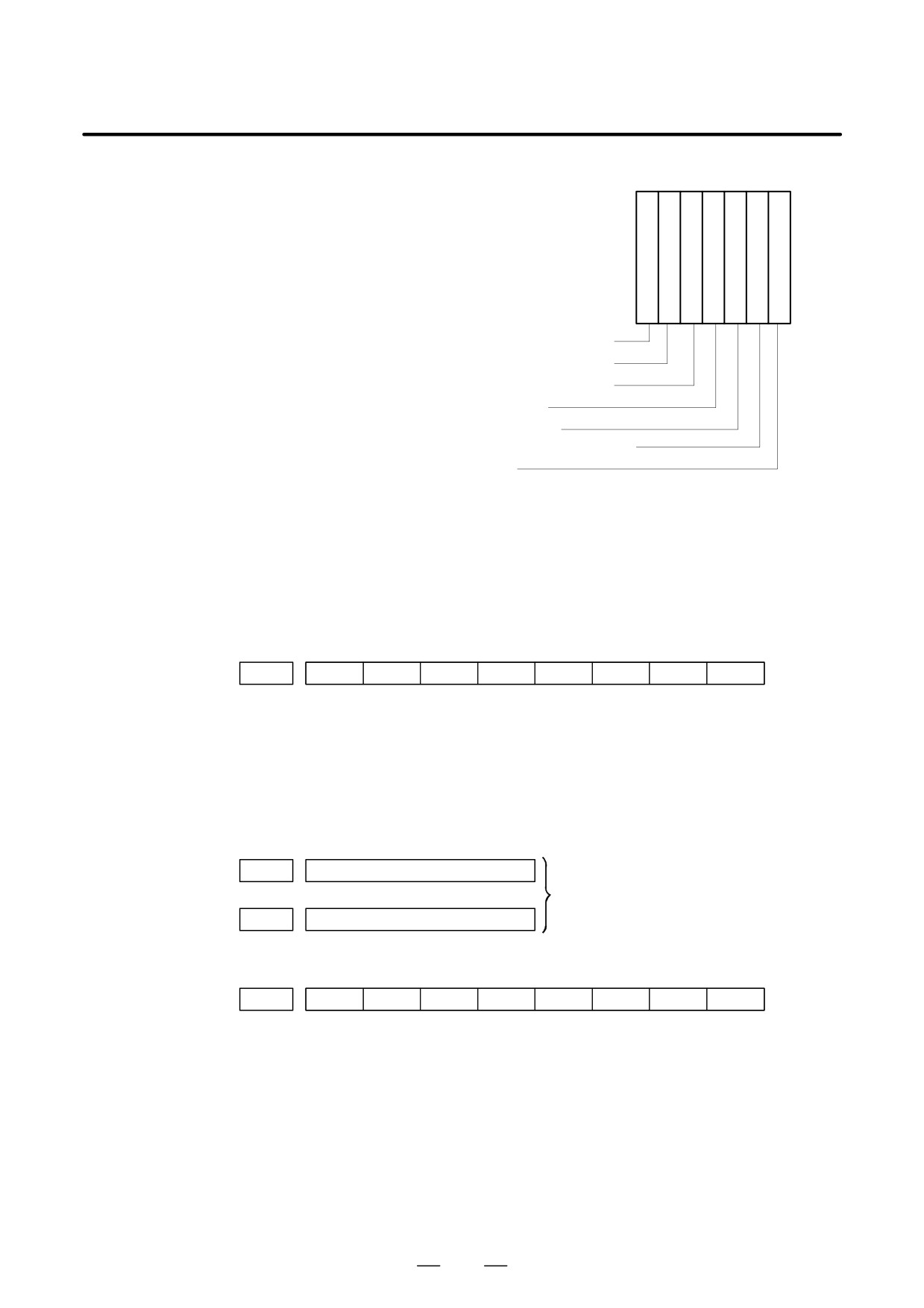
General signals are displayed in the following format:
G 0 0 0 0 . 7 ↑
The ↑ mark indicates that the signal is
turned on.
The ↓ mark indicates that the signal is
turned off.
Indicates the bit.
Indicates the address.
Some signals are indicated by their symbol names.
SBK ↑ (Indicates that the single block switch is turned on.)
46
B-64115EN/02
1. DISPLAY AND OPERATION
Mode selection signals and rapid traverse override signals
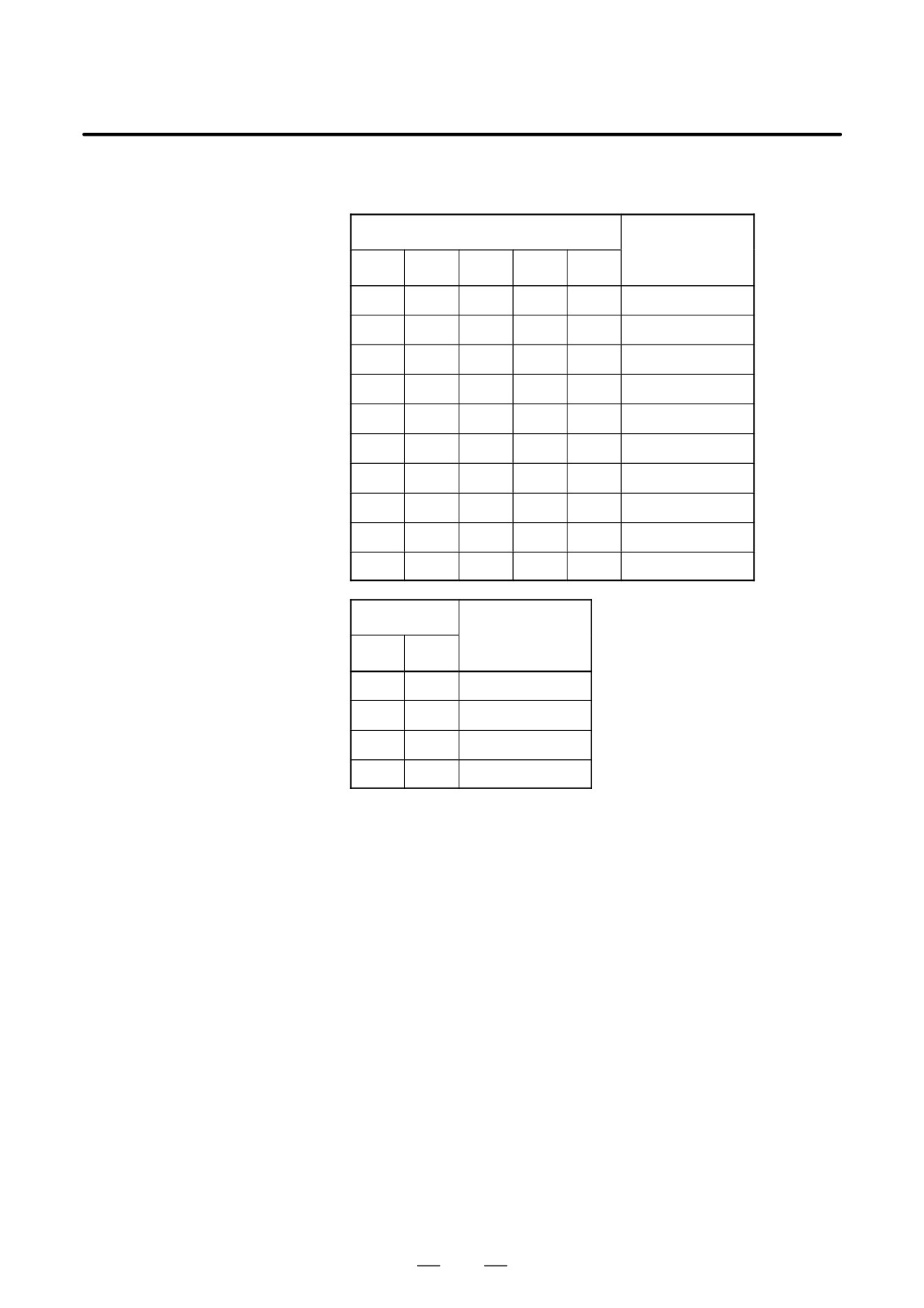
are displayed as indicated below:
Input signal
Name displayed
MD1
ND2
MD4
REF
DNC1
0
0
0
0
0
MDI
1
0
0
0
0
MEM
1
0
0
0
1
RMT
0
1
0
0
0
NOMODE
1
1
0
0
0
EDT
0
0
1
0
0
H/INC
1
0
1
0
0
JOG
1
0
1
1
0
REF
0
1
1
0
0
TJOG
1
1
1
0
0
THND
Input signal
Name displayed
ROV1
ROV2
0
0
R100%
1
0
R50%
0
1
R25%
1
1
RF0%
(3) NC alarms
NC alarms are displayed in reverse video.
P/S alarms, system alarms, and external alarms are displayed together
with their numbers.
For other types of alarms, only the alarm type is displayed. (No details
are displayed.)
(4) Time stamp (date and time)
The following time data (date and time) is recorded:
1) Date and time of power-on
2) Date and time of power-off
3) Date and time when an NC alarm occurs
4) The clock time is recorded at predetermined intervals, together
with each new calendar day.
47
1. DISPLAY AND OPERATION
B-64115EN/02
1) The power-on time is displayed as shown below:
02/01/20 ==== Year/Month/Day
09:15:30 ==== Hour:Minute:Second
2) The power-off time and the time when an NC alarm occurred are
displayed in reverse video.
02/01/20
====
Year/Month/Day
09:15:30
====
Hour:Minute:Second
If a system alarm occurs, the date and time are not recorded.
3) At predetermined intervals, the clock time is displayed in reverse
video. Set the interval in minutes in parameter No. 3122. If zero
is set, the time is stamped at ten-minute intervals.
09:15:30
====
Hour:Minute:Second
Each new calendar day is displayed in reverse video.
02/01/20
====
Year/Month/Day
CAUTION
1
The clock time is recorded for a specified interval only when
data is stored within that interval.
2
If a system alarm is issued, the system alarm occurrence
time is used for power-off display.
D Input signal or output
(1) P ress the
SYSTEM
function key.
signal to be recorded in
the operation history
(2) Press the continuous menu key [
]. The [OPEHIS] (operation
history) soft key is displayed.
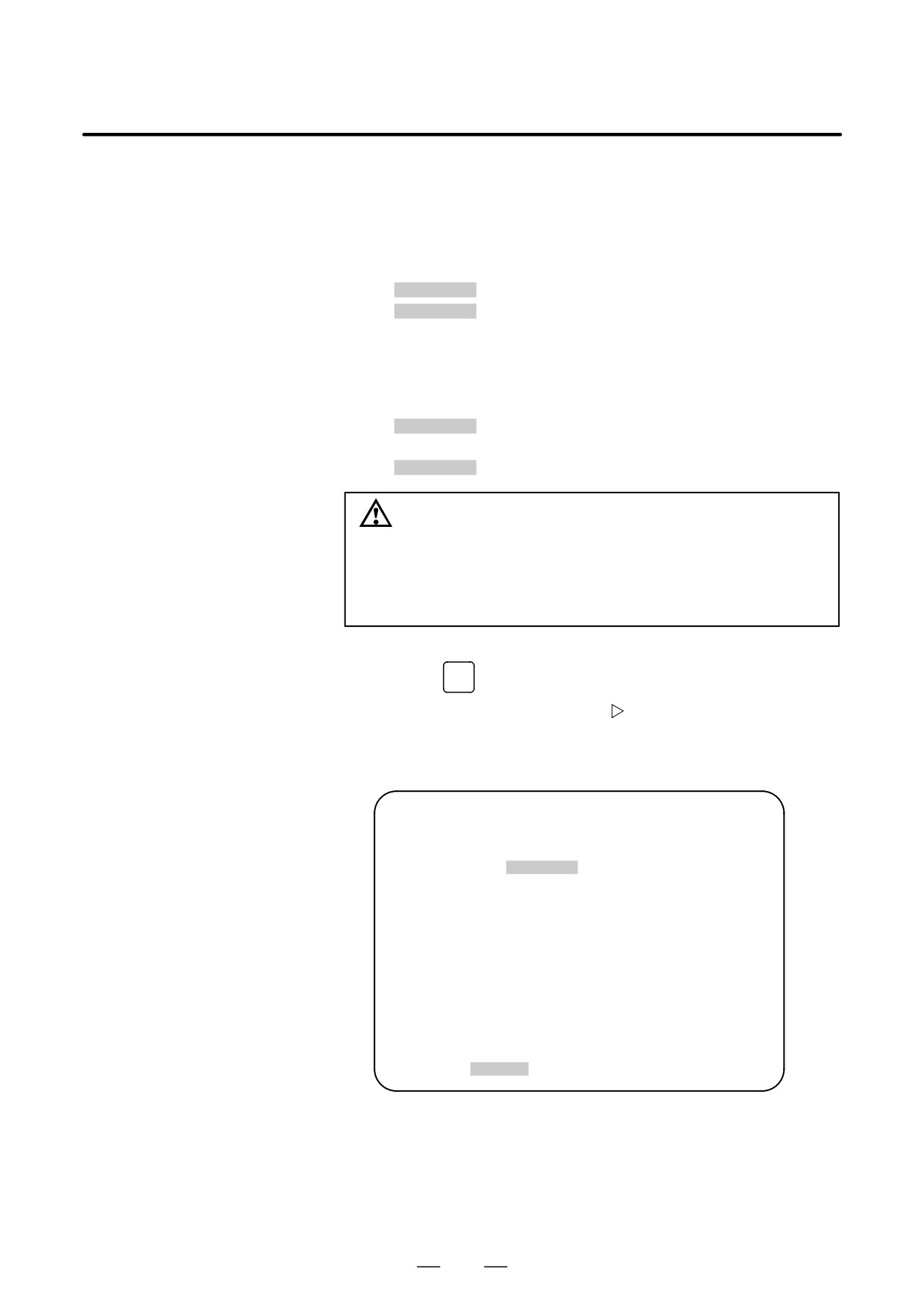
(3) Press the [OPEHIS] soft key, then press the [SG-SEL] soft key. The
operation history signal selection screen is displayed.
OP_HIS SIGNAL SELECT
O1000 N02000
No. ADDRES SIGNAL
No. ADDRES SIGNAL
01
X0000
00001000
11
G0000
00000001
02
X0004
10000000
12
G0004
00000011
03
X0008
00001100
13
G0008
00000111
04
X0009
00111000
14
G0003
00001111
05
X0012
00001111
15
G0043
01100000
06
Y0000
01000000
16
********
07
Y0004
00110000
17
********
08
Y0007
00011100
18
********
09
Y0008
00011100
19
********
10
Y0010
00011100
20
********
>
EDIT
**** *** * * *
00:00:00
[OPEHIS] [SG-SEL] [
] [
] [ (OPE) ]
48
B-64115EN/02
1. DISPLAY AND OPERATION
1.6.3
(1) On the operation history signal selection screen, press the [(OPRT)]
soft key.
Setting the Input Signal
or Output Signal to be
OP_HIS SIGNAL SELECT
O1000 N02000
Recorded in the
No. ADDRES SIGNAL
No. ADDRES SIGNAL
Operation History
01
G0004
00000010
11
********
02
********
12
********
03
********
13
********
04
********
14
********
05
********
15
********
06
********
16
********
07
********
17
********
08
********
18
********
09
********
19
********
10
********
20
********
>
EDIT **** *** *** *** 00:00:00
[ ALLDEL ][ DELETE ][ ON:1 ][ OFF:0 ][
]
(2) Press the cursor key
or
to position the cursor to a desired
position.
(3) Key in a signal type (X, G, F, or Y) and an address, then press the
INPUT
key.
Example) G0004
INPUT
Signal address G0004 is set in the ADDRES column. The corresponding
position in the SIGNAL column is initialized to 000000000.
(4) Select the bit to be recorded.
To select all bits of the specified signal address, press the [ON:1] soft
key while the cursor is positioned to 00000000 .
To select a particular bit, position the cursor to that bit by pressing the
cursor key
or
, then press the [ON:1] soft key. To cancel
a selection made by pressing the [ON:1] soft key or to cancel a
previously selected signal, press the [OFF:0] soft key.
(5) Up to 20 addresses can be specified by means of this signal selection.
These addresses need not always be specified at consecutive positions,
starting from No.1.
(6) Pressing the [ALLDEL] and [EXEC] soft keys deletes all data. If the
[ALLDEL] key is pressed by mistake, it can be cancelled by pressing
the [CAN] key.
(7) To delete a selected signal address, position the cursor to the
corresponding position then press the [DELETE] and [EXEC] soft
keys. In the SIGNAL column, asterisks ******** are displayed in
place of the deleted data. In the ADDRES column, the corresponding
position is cleared.
If the [DELET] key is pressed by mistake, it can be cancelled by
pressing the [CAN] key.
(8) Pressing the return menu key [
] causes the [OPEHIS] (OPE) soft
key to be displayed again.
49
1. DISPLAY AND OPERATION
B-64115EN/02
D Parameter-based setting
By setting bit 4 (PHS) of parameter No. 3206, setting and display on the
operation history signal selection screen can be linked with parameter No.
12801 through No. 12900. By this linking, setting information related to
input and output signals subject to operation history processing can be
input and output in the same way as ordinary parameters.
D Input signals and output
signals to be recorded in
the history
NOTE
1
A cross (×) indicates that a signal will not be recorded. Also,
any signal for which an address is not specified will not be
recorded, either.
2
A circle (f) indicates that a signal can be recorded.
3
A signal indicated by its symbol name will also be displayed
by its symbol name.
1. M/T addresses
MT→PMC
#7
#6
#5
#4
#3
#2
#1
#0
X000
f
f
f
f
f
f
f
f
to
X127
f
f
f
f
f
f
f
f
PMC→CNC
#7
#6
#5
#4
#3
#2
#1
#0
G000
f
f
f
f
f
f
f
f
to
G003
f
f
f
f
f
f
f
f
G004
f
f
f
f
FIN
f
f
f
G005
f
f
f
f
TFIN
SFIN
f
MFIN
G006
f
f
f
f
f
*ABS
f
SRN
G007
RLSOT
EXLM
*FLUP
f
f
ST
STLK
f
G008
ERS
RRW
*SP
*ESP
f
f
f
*IT
G009
f
f
f
f
f
f
f
f
to
G013
f
f
f
f
f
f
f
f
G014
f
f
f
f
f
f
f
f
G015
f
f
f
f
f
f
f
f
to
G018
f
f
f
f
f
f
f
f
G019
RT
f
f
f
f
f
f
f
50
B-64115EN/02
1. DISPLAY AND OPERATION
#7
#6
#5
#4
#3
#2
#1
#0
G020
f
f
f
f
f
f
f
f
to
G042
f
f
f
f
f
f
f
f
G043
f
×
f
×
×
f
f
f
G044
f
f
f
f
f
f
MLK
BDT1
G045
BDT9
BDT8
BDT7
BDT6
BDT5
BDT4
BDT3
BDT2
G046
DRN
KEY4
KEY3
KEY2
KEY1
f
SBK
f
G047
f
f
f
f
f
f
f
f
to
G060
f
f
f
f
f
f
f
f
G061
f
f
f
f
f
f
f
RGTA
G062
f
f
f
f
f
f
f
f
to
G099
f
f
f
f
f
f
f
f
G100
+J8
+J7
+J6
+J5
+J4
+J3
+J2
+J1
G101
f
f
f
f
f
f
f
f
G102
-J8
-J7
-J6
-J5
-J4
-J3
-J2
-J1
G103
f
f
f
f
f
f
f
f
to
G105
f
f
f
f
f
f
f
f
G106
MI8
MI7
MI6
MI5
MI4
MI3
MI2
MI1
G107
f
f
f
f
f
f
f
f
G108
MLK8
MLK7
MLK6
MLK5
MLK4
MLK3
MLK2
MLK1
G109
f
f
f
f
f
f
f
f
G110
+LM8
+LM7
+LM6
+LM5
+LM4
+LM3
+LM2
+LM1
G111
f
f
f
f
f
f
f
f
G112
-LM8
–LM7
-LM6
-LM5
-LM4
-LM3
-LM2
-LM1
G113
f
f
f
f
f
f
f
f
G114
*+L8
*+L7
*+L6
*+L5
*+L4
*+L3
*+L2
*+L1
51
1. DISPLAY AND OPERATION
B-64115EN/02
#7
#6
#5
#4
#3
#2
#1
#0
G115
f
f
f
f
f
f
f
f
G116
*-L8
*-L7
*-L6
*-L5
*-L4
*-L3
*-L2
*-L1
G117
f
f
f
f
f
f
f
f
G118
*+ED8
*+ED7
*+ED6
*+ED5
*+ED4
*+ED3
*+ED2
*+ED1
G119
f
f
f
f
f
f
f
f
G120
*-ED8
*-ED7
*-ED6
*-ED5
*-ED4
*-ED3
*-ED2
*-ED1
G121
f
f
f
f
f
f
f
f
to
G125
f
f
f
f
f
f
f
f
G126
SVF8
SVF7
SVF6
SVF5
SVF4
SVF3
SVF2
SVF1
G127
f
f
f
f
f
f
f
f
to
G129
f
f
f
f
f
f
f
f
G130
*IT8
*IT7
*IT6
*IT5
*IT4
*IT3
*IT2
*IT1
G131
f
f
f
f
f
f
f
f
G132
f
f
f
f
+MIT4
+MIT3
+MIT2
+MIT1
G133
f
f
f
f
f
f
f
f
G134
f
f
f
f
-MIT4
-MIT3
-MIT2
-MIT1
G135
f
f
f
f
f
f
f
f
to
G255
f
f
f
f
f
f
f
f
PMC→MT
#7
#6
#5
#4
#3
#2
#1
#0
Y000
f
f
f
f
f
f
f
f
to
Y127
f
f
f
f
f
f
f
f
CNC→PMC
#7
#6
#5
#4
#3
#2
#1
#0
F000
f
f
f
f
f
f
f
f
to
F255
f
f
f
f
f
f
f
f
52
B-64115EN/02
1. DISPLAY AND OPERATION
1.6.4
Recorded data can be output to an input/output unit connected via a
reader/punch interface. An output record can be input from the
Inputting and
input/output unit.
Outputting the
Set the input/output unit to be used in setting parameters No. 0020 and
Operation History Data
0100 to 0135.
To output the data, set a code in the ISO bit of a setting parameter (bit 1
of parameter No. 0020).
D Output
(1) Select EDIT mode.
(2) Press the
SYSTEM
key, then select the operation history display screen.
(3) Press the soft keys [(OPRT)],
, [PUNCH], and [EXEC] in this
order.
The data output to the FANUC Floppy Cassette or FANUC FA Card is
stored under file name OPERATION HISTORY.
D Input
(1) Select EDIT mode.
(2) Press the
SYSTEM
key, then select the operation history display screen.
(3) Press the soft keys [(OPRT)],
, [READ], and [EXEC] in this
order.
D Output data format
1. MDI/soft key
2. Signal
3. Alarm
4. For extension (date or time)
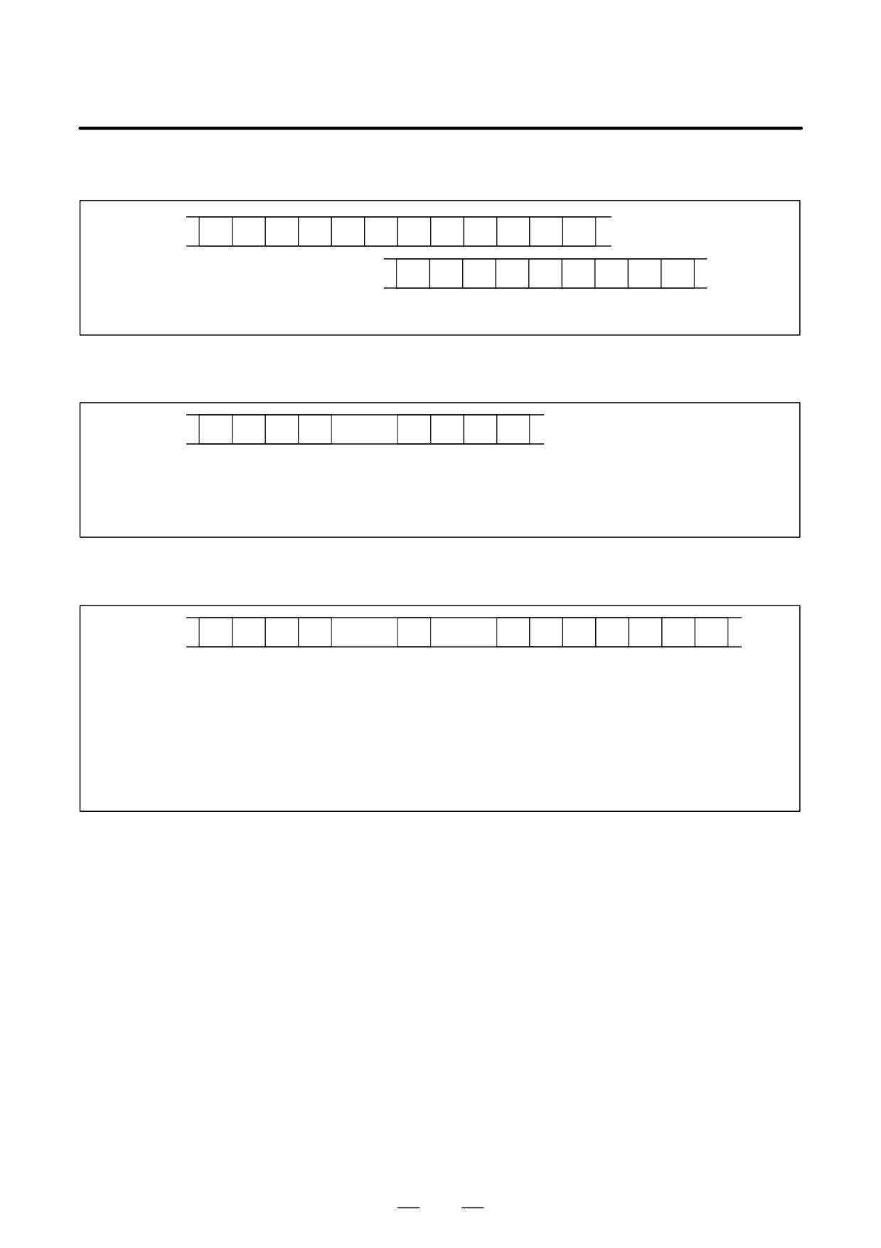
The header and recorded operation data are output, in this order. The
operation history data is divided into four parts by identifier words. Data
other than the identifier words depends on the type.
T(identifier word)
T0
: Header
T50
: MDI/soft key
T51
: Signal
T52
: Alarm
T53
: For extension (date or time)
53
1. DISPLAY AND OPERATION
B-64115EN/02
1) Header
T
0
C
O
P
E
R
A
T
I
O
N
H
I
S
T
O
R
Y
;
C: Data word
2) MDI/soft key
T
5
0
P
0 to 1
H
*
;
P0: Usually
P1: At power-on
H **:
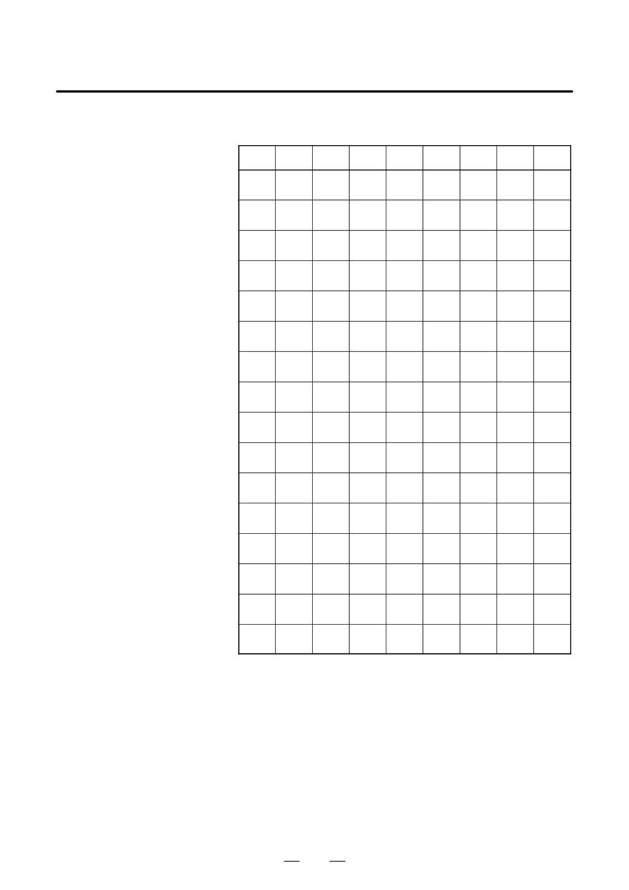
Key code (See the following table.)
3) Signal
T
5
1
P
0
to 6
N
0 to 255
H
*
*
,
*
;
New data Old data
P0: X0000 and above
P2: G0000 and above
P4: Y0000 and above
P6: F0000 and above
N***: DI/DO number
H **: Signal information data (hexadecimal)
54
B-64115EN/02
1. DISPLAY AND OPERATION
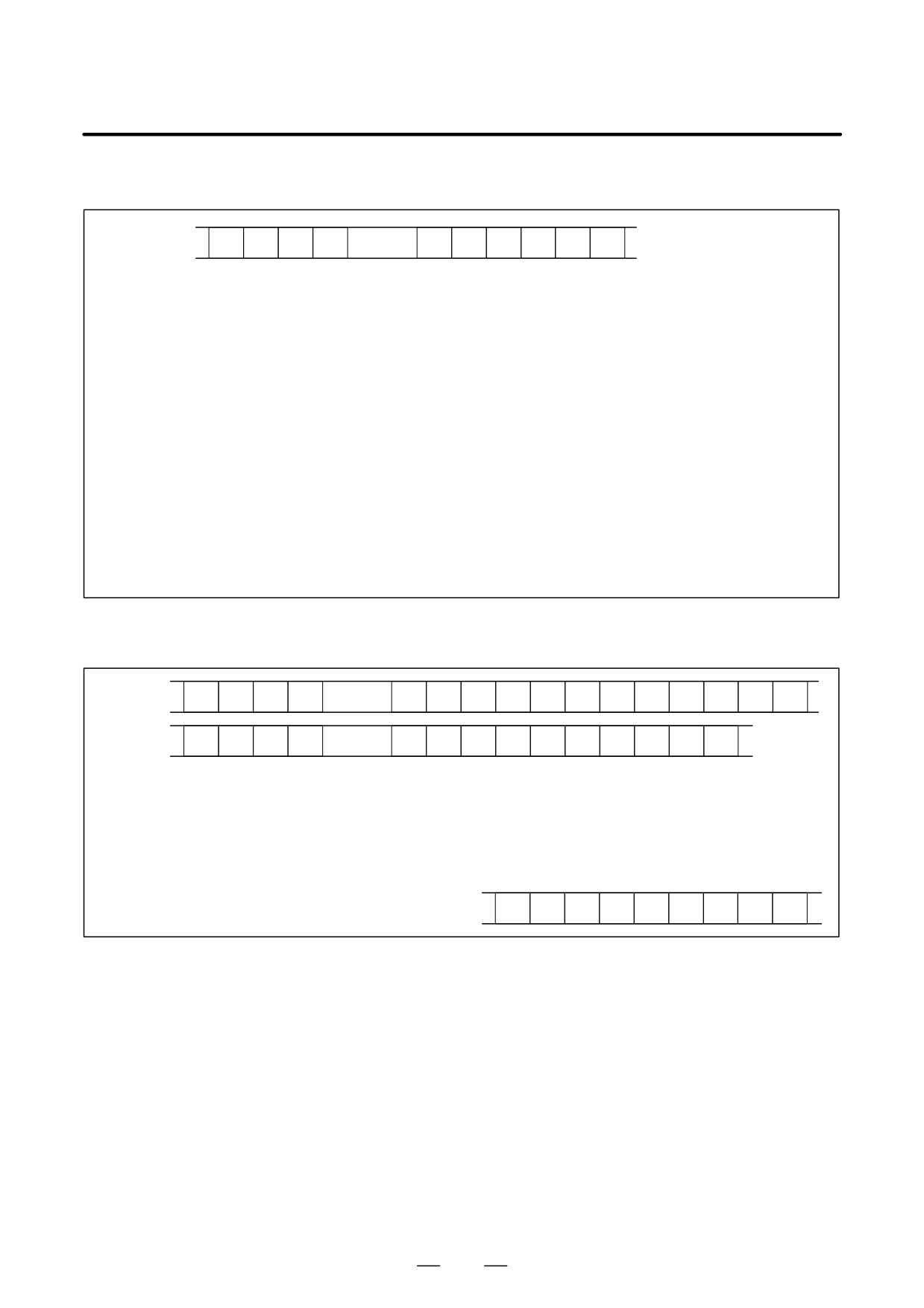
4) Alarm
T
5
2
P
0 to 10
N
*
;
P0: P/S No. 100
P1: P/S No. 000
P2: P/S No. 101
P3: P/S No. 0001 to 254
P4: Overtravel alarm
P5: Overheat alarm
P6: Servo alarm
P7: System alarm
P8: APC alarm
P9: Spindle alarm
P10: P/S alarm No. 5000 to 5999
P15: External alarm
N****: Alarm number (for P/S alarm, system alarm, and external
alarm only)
5) For extension (date or time)
Date
T
5
3
P
0 to 1
E
0
D
;
Time
T
5
3
P
0 to 1
E
1
D
;
P0: Usually
P1: At power-on
E0: Date
E1: Time
D*..*: Data Example) June 29, 2002
D
2
0
0
2
0
6
2
9
55
1. DISPLAY AND OPERATION
B-64115EN/02
Key codes (MDI/soft key)
(00H to 7FH)
0
1
2
3
4
5
6
7
0
Space
0
@
P
1
!
1
A
Q
2
”
2
B
R
3
#
3
C
S
4
$
4
D
T
5
%
5
E
U
6
&
6
F
V
7
’
7
G
W
8
(
8
H
X
9
)
9
I
Y
A
;
:
J
Z
(EOB)
B
+
K
[
C
’
<
L
¥
D
-
=
M
]
E
>
N
F
/
?
O
-
56

B-64115EN/02
1. DISPLAY AND OPERATION
(80H to FFH)
8
9
A
B
C
D
E
F
0
Reset
F0
1
MMC
F1
2
CNC
F2
3
F3
4
Shift
Insert
F4
5
Delete
F5
6
CAN
Alter
F6
7
F7
8
Cur→
Input
POS
F8
9
Cur←
PROG
F9
A
Cur↓
Help
OFFSET
*
SETTING
B
Cur↑
SYSTEM
C
MESSAGE
D
CUSTOM
GRAPH
*1*
E
Page↓
CUSTOM
FR
F
Page↑
Fapt
FL
*
CUSTOM
*1:On the small-sized keyboard, ED corresponds to the
GRAPH
key. On
a standard keyboard, ED corresponds to the
GRAPH
key and EE to the
CUSTOM
key.
* : Command key
57
1. DISPLAY AND OPERATION
B-64115EN/02
1.6.5
(1) While the operation history screen is displayed, no information can be
recorded to the history.
Notes
(2) An input signal having an on/off width of up to 16 msec is not recorded
in the history. Some signals are not recorded in the history.
(3) Once the storage becomes full, old data is deleted, starting from the
oldest record. Up to about 8000 key information items can be
recorded.
(4) The recorded data is retained even after the power is turned off. A
memory all clear operation, however, erases the recorded data.
(5) The operation history function cannot execute sampling when the
OHS bit (bit 7 of parameter No. 3106) is set to 1.
(6) Set the date and time on the setting screen.
(7) The time needed to input and output 6000 operation records at a rate
of 4800 baud is as follows:
Output:About 5 minutes
Input: About 2 minutes and 30 seconds
This file corresponds to a paper tape of about 180 m in length.
58
B-64115EN/02
1. DISPLAY AND OPERATION
1.7
HELP FUNCTION
The help function displays alarm information, operation method and a
1.7.1
table of contents for parameters. This function is used as a handbook.
General
1.7.2
Display Method
D Display of help screen
Press
HELP
key on any screen other than PMC screen, then a help screen
appears.
(However, it is not available when PMC screen/CUSTOM screen is
displaying)
HELP (INITIAL MENU)
O1234 N12345
*****
HELP
*****
1. ALARM DETAIL
2. OPERATION METHOD
3. PARAMETER TABLE
[ALARM]
[OPERAT]
[PARAM]
[
]
[
]
D Help for alarm
(1) When an alarm is generated, press soft key [ALARM], then a help
message of the alarm is displayed.
HELP (INITIAL MENU)
O1234 N12345
NUMBER
: 010
M’SAGE
: IMPROPER G CODE
FUNCTION
:
ALARM
:
A G CODE NOT LISTED IN G-CODE TABLE
IS BEING COMMANDED
ALSO G-CODE FOR FUNCTION NOT ADDED
IS BEING COMMANDED
[ALARM]
[OPERAT]
[PARAM] [
] [ (OPRT) ]
(2) Pressing soft key [OPERAT],(alarm No.), and soft key [SELECT]
in this order, a help message corresponding to the input alarm number
is displayed.
59
1. DISPLAY AND OPERATION
B-64115EN/02
D Help for operation
(1) Press [(OPRT)], then a menu for operation method is displayed.
HELP (OPERATION METHOD)
O1234 N12345
1. PROGRAM EDIT
2. SEARCH
3. RESET
4. DATA INPUT WITH MDI
5. DATA INPUT WITH TAPE
6. OUTPUT
7. INPUT WITH FANUC CASSETTE
8. OUTPUT WITH FANUC CASSETTE
9. MEMORY CLEAR
[ALARM]
[OPRERAT]
[PARAM] [
]
[(OPRT)]
(2) Press [(OPRT)], (an item number) and soft key [SELECT], then an
operation method of the item is displayed.
PAGE
Pressing PAGE key
or
displays another pages.
PAGE
HELP (OPERATION METHOD)
O1234 N12345
<<1.PROGRAM EDIT>>
1/4
Current
page/ Total
DELETE ALL PROGRAMS
page
MODE :EDIT
SCREEN :PROGRAM
OPR
:(0-9999) - (DELETE)
DELETE ONE PROGRAM
MODE : EDIT
SCREEN : PROGRAM
OPR
:(0+PROGRAM NUMBER) - <DELETE>
[
]
[
]
[
]
[
]
[SELECT]
60
B-64115EN/02
1. DISPLAY AND OPERATION
D Parameter table
Press soft key [PARAM], then a parameter table is displayed.
HELP (PARAMETER TABLE)
O1234 N12345
1/4
Current
page/ Total
·SETTING
(NO.0000~ )
page
·READER/PUNCHER INTERFACE
(NO.0100~ )
·AXIS CONTROL/SETTING UNIT
(NO.1000~ )
·COORDINATE SYSTEM
(NO.1200~ )
·STROKE LIMIT
(NO.1300~ )
·FEED RATE
(NO.1400~ )
·ACCEL/DECELERATION CTRL
(NO.1600~ )
·SERVO RELATED
(NO.1800~ )
·DI/DO
(NO.3000~ )
[ ALARM ] [OPERAT][
PARAM
] [
][SELECT]
PAGE
Another screen can be selected by the PAGE key
or
PAGE
61

1. DISPLAY AND OPERATION
B-64115EN/02
1.8
DISPLAYING
DIAGNOSTIC PAGE
1.8.1
(1) Press
SYSTEM
key.
Displaying Diagnostic
(2) Press soft key [DGNOS], then a diagnostic screen is displayed.
Page
1.8.2
Contents Displayed
D Causes when the
000 WAITING FOR FIN SIGNAL
An auxiliary function is being
machine does not travel
executed.
in spite of giving a
001 MOTION
Travel command of cycle
command
operation is being executed.
002 DWELL
DWELL Dwell is being executed.
003 IN-POSITION CHECK
In-position check is being done.
004 FEEDRATE OVERRIDE 0%
Feedrate override is 0%.
005 INTERLOCK/START LOCK
Interlock or start lock is input.
006 SPINDLE SPEED ARRIVAL CHECK
Waiting for spindle speed
arrival signal.
010 PUNCHING
Data is being output through
reader/puncher interface.
011 READING
Data is being input through
reader/puncher interface.
012 WAITING FOR (UN) CLAMP
Waiting for the end of index
table indexing
013 JOG FEEDRATE OVERRIDE 0%
Manual feedrate override is 0%.
014 WAITING FOR RESET, ESP,RRW OFF
NC is in reset state.
015 EXTERNAL PROGRAM NUMBER SEARCH
External Program Number
Search External program
number search is being done
016 BACKGROUND ACTIVE
Background is being used.
62
B-64115EN/02
1. DISPLAY AND OPERATION
D Cause of the cycle start
LED turned off
020 CUT SPEED UP/DOWN
1
0
0
0
1
0
0
021 RESET BUTTON ON
0
0
1
0
0
0
0
022 RESET AND REWIND ON
0
0
0
1
0
0
0
023 EMERGENCY STOP ON
1
0
0
0
0
0
0
024 RESET ON
1
1
1
1
0
0
0
025 STOP MOTION OR DWELL
1
1
1
1
1
1
0
Input of emergency stop signal
Input of external reset signal
Reset button On of MDI
Input of reset & rewind
Servo alarm generation
Switching to other mode, Feed hold
Single block stop
D State of TH alarm
030 CHARACTER NUMBER TH ALARM Position of the character that
caused TH alarm. The position
is counted from the head.
031 TH DATA
Data of the character that caused
TH alarm.
D Screen hardcopy status
#7
#6
#5
#4
#3
#2
#1
#0
DGN
035
HCRE3
HCRE2
HCRE1
Hcab3
hcend
#4(HCRE3):
Memory card writing failure (P/S5214)
#3(HCRE2):
Memory card exclusive right acquisition failure (P/S5213)
#2(HCRE1):
Hardcopy parameter setting error (P/S5212)
#1(Hcab3):
Hardcopy interrupt request acceptance
#0(hcend):
Hardcopy normal end
DGN
040
Not used in the FANUC Series
to
0i/0i Mate-MODEL C.
DGN
046
D Details of serial pulse
coder
#7
#6
#5
#4
#3
#2
#1
#0
DGN
200
OVL
LV
OVC
HCA
HVA
DCA
FBA
OFA
#7(OVL): Overload alarm
#6(LV): Insufficient voltage alarm
#5(OVC): Over current alarm
#4(HCA): Abnormal current alarm
#3(HVA): Overvoltage alarm
#2(DCA): Discharge alarm
#1(FBA): Disconnection alarm
#0(OFA): Overflow alarm
63
1. DISPLAY AND OPERATION
B-64115EN/02
#7
#6
#5
#4
#3
#2
#1
#0
DGN
201
ALD
EXP
Overload
0
-
-
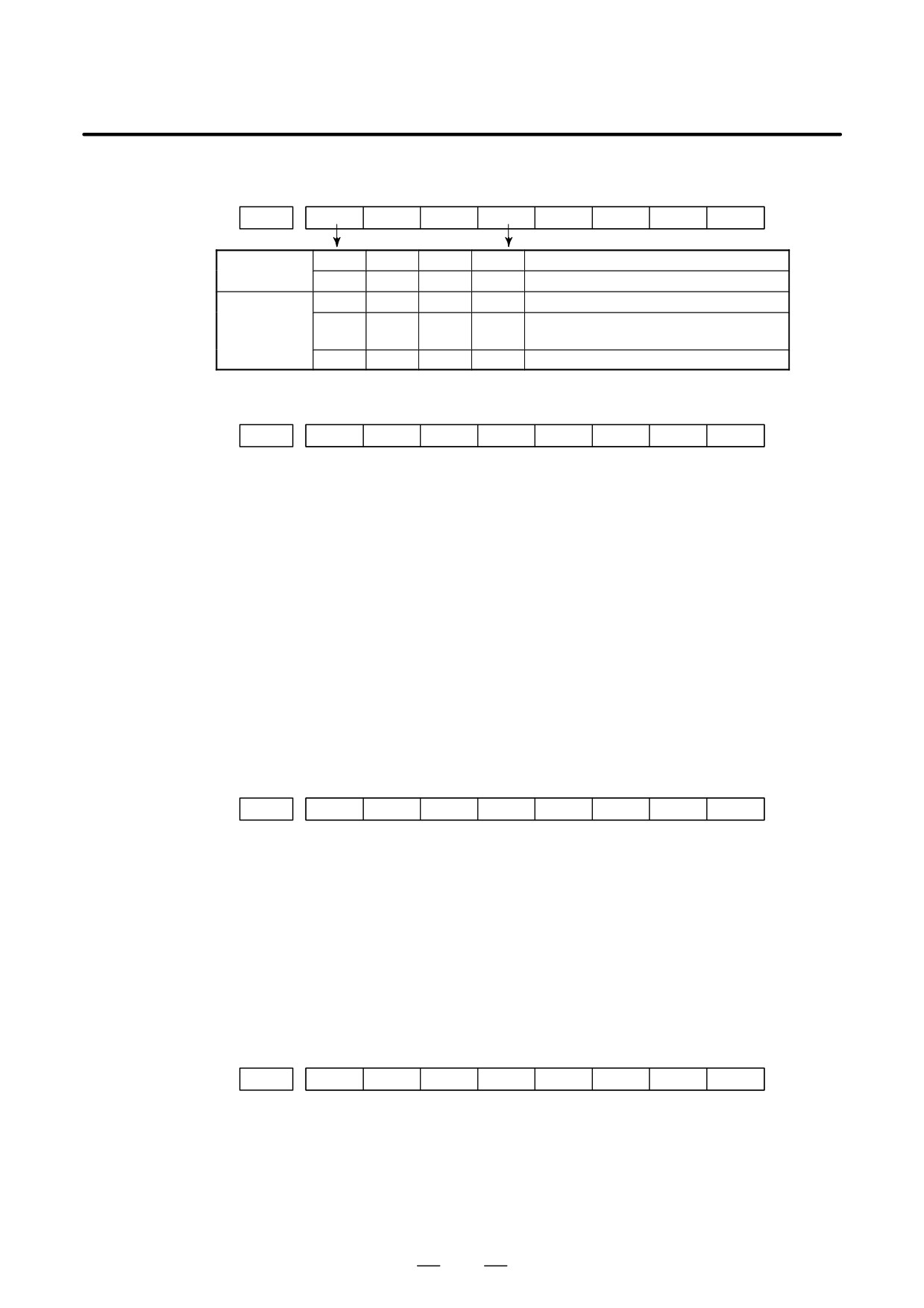
-
Amplifier overheat
alarm
1
-
-
-
Motor overheat
Disconnec-
1
-
-
0
Built-in pulse coder (hand)
tion alarm
1
-
-
1
Disconnection of separated type pulse
coder (hard)
0
-
-
0
Disconnection of pulse coder (software)
#7
#6
#5
#4
#3
#2
#1
#0
DGN
202
CSA
BLA
PHA
RCA
BZA
CKA
SPH
#6(CSA):
Hardware of serial pulse coder is abnormal
#5(BLA):
Battery voltage is low (warning)
#4(PHA):
Serial pulse coder or feedback cable is erroneous.
Counting of feedback cable is erroneous.
#3(RCA):
Serial pulse coder is faulty.
Counting of feedback cable is erroneous.
#2(BZA):
Battery voltage became 0.
Replace the battery and set the reference position.
#1(CKA):
Serial pulse coder is faulty.
Internal block stopped.
#0(SPH):
Serial pulse coder or feedback cable is faulty.
Counting of feedback cable is erroneous.
#7
#6
#5
#4
#3
#2
#1
#0
DGN
203
DTE
CRC
STB
PRM
#7(DTE): Communication failure of serial pulse coder.
There is no response for communication.
#6(CRC): Communication failure of serial pulse coder.
Transferred data is erroneous.
#5(STB): Communication failure of serial pulse coder.
Transferred data is erroneous.
#4(PRM): The alarm is detected by the servo, the values specified in the parameter is
not correct.
#7
#6
#5
#4
#3
#2
#1
#0
DGN
204
OFS
MCC
LDA
PMS
#6(OFS): Abnormal current value result of A/D conversion of digital
#5(MCC): Contacts of MCC of servo amplifier is melted.
#4(LDA): Serial pulse coder LED is abnormal
#3(PMS): Feedback is not correct due to faulty serial pulse coder C or feedback
cable.
64
B-64115EN/02
1. DISPLAY AND OPERATION
D Details of separate serial
pulse coder alarms
#7
#6
#5
#4
#3
#2
#1
#0
DGN
205
OHA
LDA
BLA
PHA
CMA
BZA
PMA
SPH
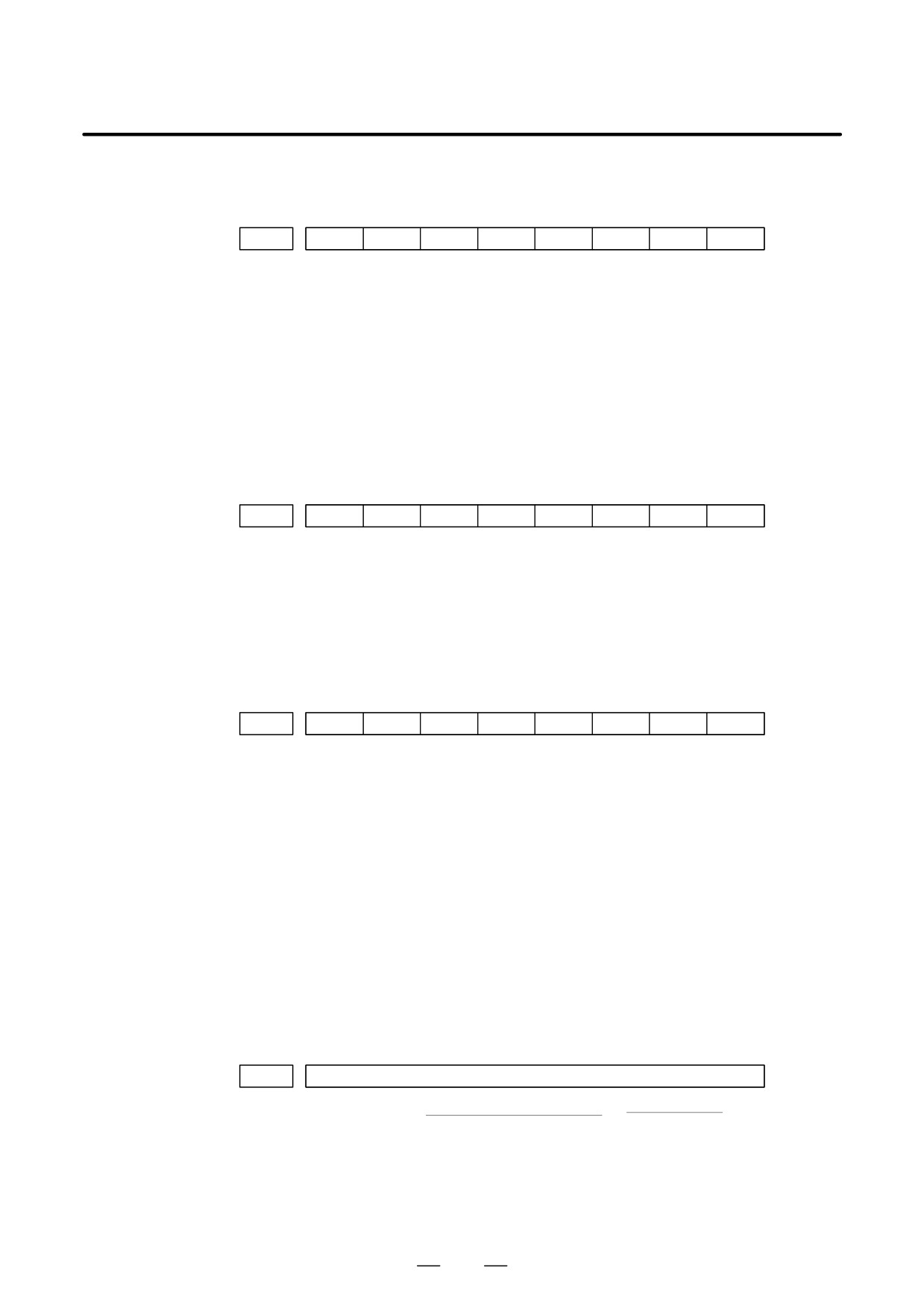
#7(OHA): Overheat occurred in the separate pulse coder.
#6(LDA): An LED error occurred in the separate pulse coder.
#5(BLA): A low battery voltage occurred in the separate pulse coder.
#4(PHA): A phase data error occurred in the separate linear scale.
#3(CMA): A count error occurred in the separate pulse coder.
#2(BZA): The battery voltage for the separate pulse coder is zero.
#1(PMA): A pulse error occurred in the separate pulse coder.
#0(SPH): A soft phase data error occurred in the separate pulse coder.
#7
#6
#5
#4
#3
#2
#1
#0
DGN
206
DTE
CRC
STB
#7(DTE):
A data error occurred in the separate pulse coder.
#6(CRC):
A CRC error occurred in the separate pulse coder.
#5(STB):
A stop bit error occurred in the separate pulse coder.
D Details of invalid servo
If servo alarm No. 417 is generated and bit 4 of diagnosis No. 203 is 0,
parameter alarms (on the
indicates the cause.
CNC side)
If bit 4 of diagnosis No. 203 is 1, refer to diagnosis No. 352.
#7
#6
#5
#4
#3
#2
#1
#0
DGN
280
AXS
DIR
PLS
PLC
MOT
#0(MOT):
The motor type specified in parameter No. 2020 falls outside the
predetermined range.
#2(PLC):
The number of velocity feedback pulses per motor revolution, specified in
parameter No. 2023, is zero or less. The value is invalid.
#3(PLS):
The number of position feedback pulses per motor revolution, specified in
parameter No. 2024, is zero or less. The value is invalid.
#4(DIR):
The wrong direction of rotation for the motor is specified in parameter No.
2022 (the value is other than 111 or -111).
#6(AXS):
In parameter No. 1023 (servo axis number), a value that falls outside the
range of 1 to the number of controlled axes is specified. (For example, 4 is
specified instead of
3.)
Alternatively, the values specified in the
parameter are not consecutive.
D Position error amount
DGN
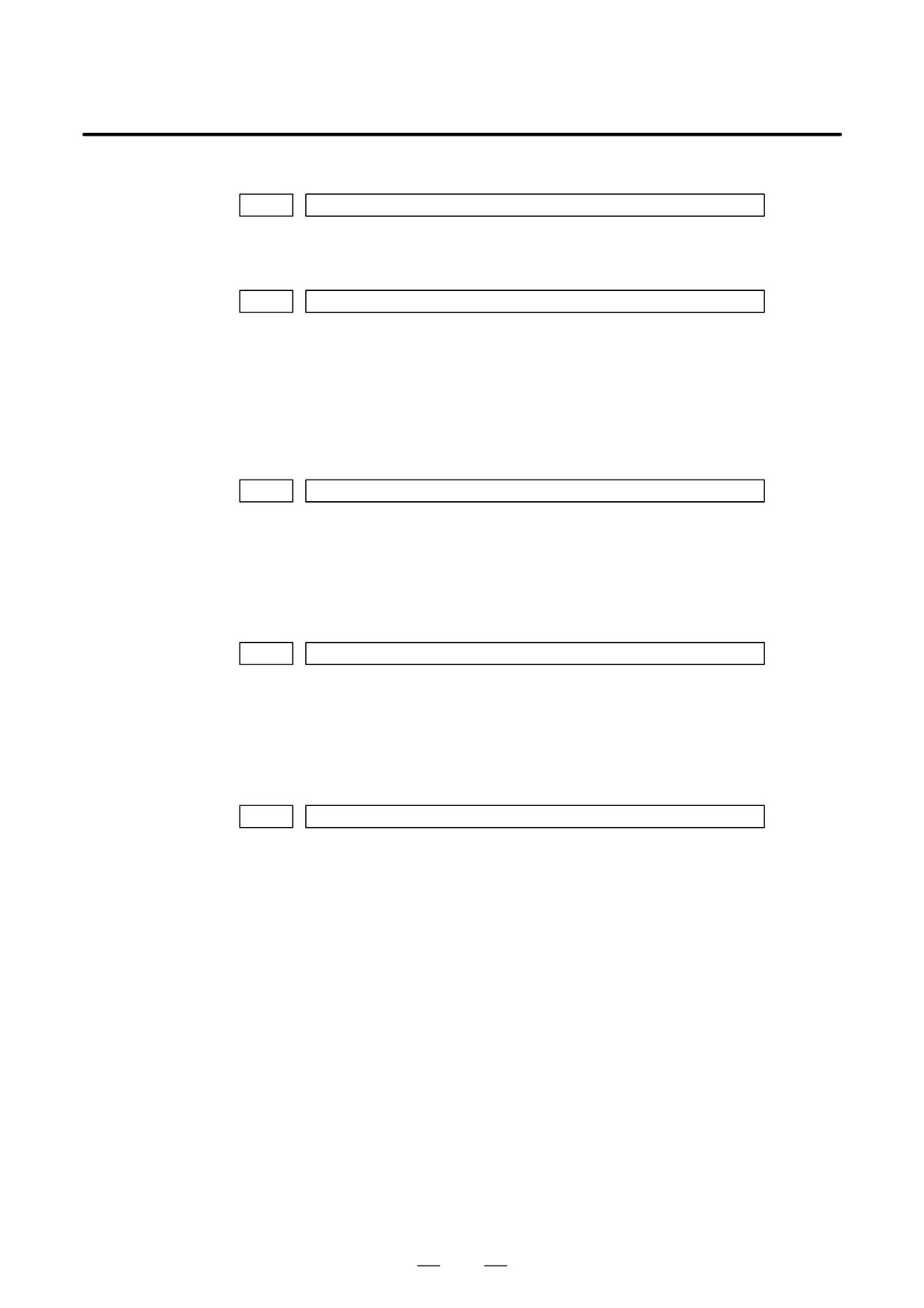
300
Position error of an axis in detection unit
Feed rate [mm/min]
1
Position error=
×
60 servo loop gain [1/sec]
Detection unit
65
1. DISPLAY AND OPERATION
B-64115EN/02
D Machine position
DGN
301
Distance from reference position of an axis in detection unit
D Reference position shift
function
DGN
302
Distance from the end of the deceleration dog to the first grid point
[Data type]
Two-word axis
[Units of data]
0.001 mm (metric output), 0.0001 inch (inch output)
[Valid data range]
-99999999 to 99999999
D Position deviation with
fine acceleration/
deceleration enabled
DGN
303
Position deviation with fine acceleration/deceleration enabled
[Data type]
Two-word axis
[Unit of data]
Detection unit
[Valid data range]
-99999999 to 99999999
D Reference counter
DGN
304
Reference counter for individual axes
[Data type]
Two-word axis
[Unit of data]
Detection unit
[Valid data range]
-99999999 to 99999999
D Displacement detection
DGN
305
Position feedback data between Z phases of individual axes
[Data type]
Two-word axis
[Unit of data]
Detection unit
[Valid data range]
-99999999 to 99999999
If displacement detection is enabled, the feedback data between the Z
phases of different axes is represented in the detection unit.
66
B-64115EN/02
1. DISPLAY AND OPERATION
D Machine coordinates of
angular axis/orthogonal
axis
DGN
306
Machine coordinates of a slant axis in the Cartesian coordinate system
DGN
307
Machine coordinates of an orthogonal axis in the Cartesian coordinate system
[Data type]
Two-word
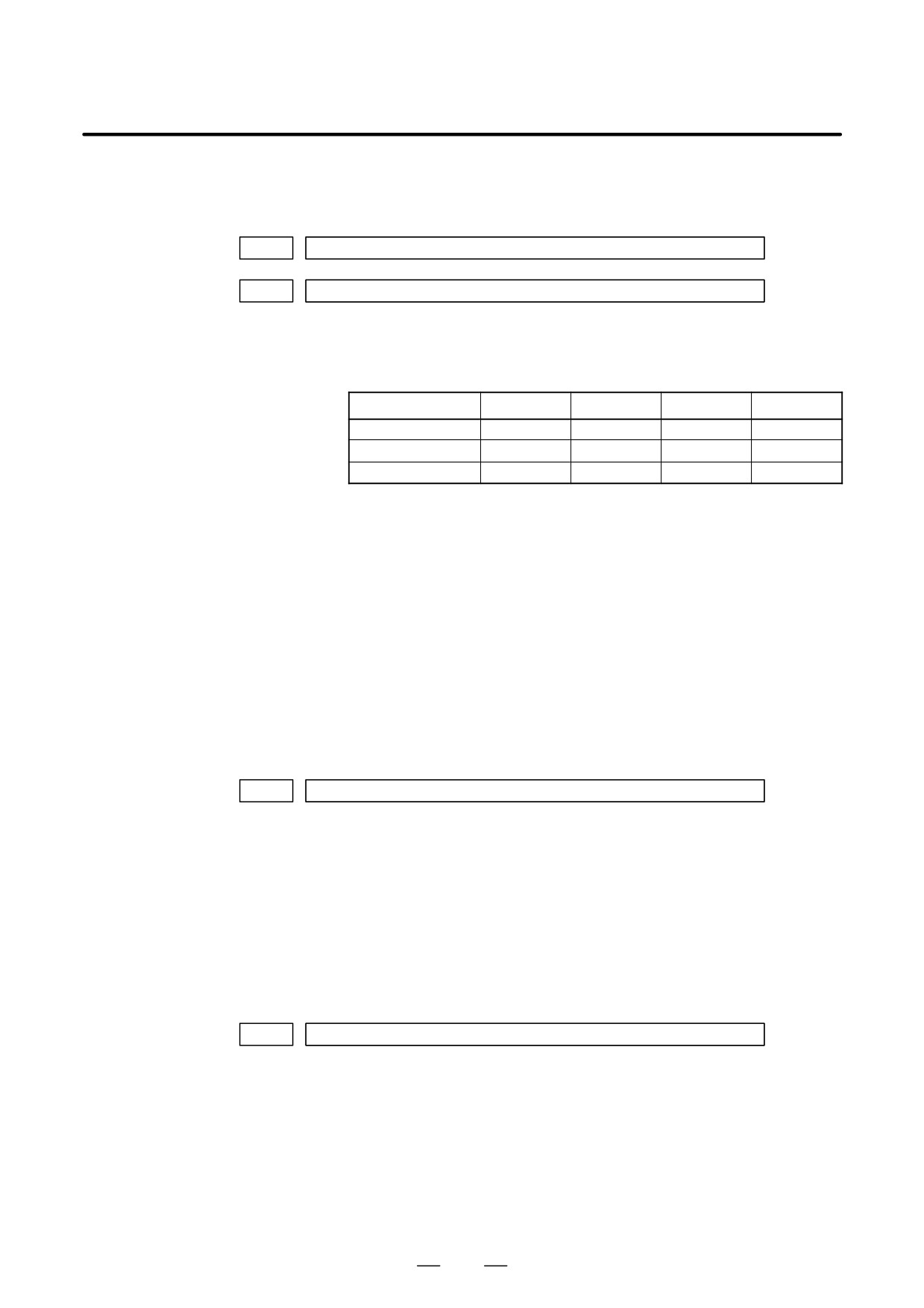
[Unit of data]
Increment system
IS-A
IS-B
IS-C
Unit
Metric input
0.01
0.01
0.01
mm
Inch input
0.001
0.001
0.001
inch
Rotation axis
0.01
0.01
0.01
deg
[Valid data range]
-99999999 to 99999999
These parameters are updated only when bit 0 (AAC) of parameter No.
8200 is set to 1, and any of the parameters below is set to 1:
D Bit 0 (AOT) of parameter No. 8201
D Bit 1 (AO2) of parameter No. 8201
D Bit 2 (AO3) of parameter No. 8201
D Bit 3 (QSA) of parameter No. 5009 (T series only)
D The interference check option is selected.
D Motor temperature
information
DGN
308
Servo motor temperature
[Data type]
Byte axis
[Unit of data]
_C
[Valid data range]
0 to 255
The αi servo motor coil temperature is indicated.
When the temperature reaches 140_C, an alarm about motor overheat is
issued.
DGN
309
Pulse coder temperature
[Data type] Byte axis
[Unit of data] _C
[Valid data range] 0 to 255
The temperature of the pulse coder printed circuit board is indicated.
When the temperature reaches
100_C (85_C for the atmosphere
temperature in the pulse coder), an alarm about motor overheat is issued.
67
1. DISPLAY AND OPERATION
B-64115EN/02
NOTE
1
The temperature data must fall within the following ranges.
50_C to 160_C "5_C
160_C to 180_C "10_C
2
The temperature at which an overheat alarm is issued has
a maximum error of 5_C.
3
Information on axes other than the αi servo axis is not
indicated.
(Indicated by ”0_C.”)
D Cause of the APZ bit (bit
With reference to the diagnosis below, you can determine the cause why
4 of parameter 1815)
the reference position return completion parameter was brought to 0.
brought to 0
#7
#6
#5
#4
#3
#2
#1
#0
DGN
310
DTH
ALP
NOF
BZ2
BZ1
PR2
PR1
#0(PR1):
The setting of the following parameters has been changed: Parameters
1821, 1850, 1860, 1861.
#1(PR2):
The setting of the ATS bit (bit 1 of parameter No. 8302) has been changed.
#2(BZ1):
The detected APC battery voltage is 0 V (Inductosyn).
#3(BZ2):
The detected APC battery voltage is 0 V (separate position detector).
#4(NOF):
The Inductosyn output no offset data.
#5(ALP):
Before the α pulse coder detects a full single rotation, reference position
establishment by parameters was attempted.
#6(DTH):
A controlled axis detach signal/parameter was input.
#7
#6
#5
#4
#3
#2
#1
#0
DGN
311
DUA
XBZ
GSG
AL4
AL3
AL2
AL1
#0(AL1):
An APC alarm was issued.
#2(AL3):
The detected APC battery voltage is 0 V (serial pulse coder).
#3(AL4):
An abnormal rotation speed (RCAL) was detected.
#4(GSG):
The G202 signal was brought from 0 to 1.
#1(AL2):
A disconnection was detected.
#6(DUA):
While the dual position feedback function was being used, the difference
in error between the semi-closed loop side and the closed loop side
became too large.
#5(XBZ):
The detected APC battery voltage is 0 V (serial separate position
detector).
68
B-64115EN/02
1. DISPLAY AND OPERATION
D FSSB status
#7
#6
#5
#4
#3
#2
#1
#0
DGN
320
CFE
ERP
OPN
RDY
OPP
CLS
Indicates the internal status of the FSSBC.
#0(CLS): Closed.
#1(OPP): Running OPEN protocol.
#2(RDY): Open and ready.
#3(OPN): Open.
#4(ERP): Running ERROR protocol.
#7(CFE): Encountered configuration error.
(The actual slave type does not match the one specified in the conversion
table.)
#7
#6
#5
#4
#3
#2
#1
#0
DGN
321
XE3
XE2
XE1
XE0
ER3
ER2
ER1
ER0
Indicates the cause of an FSSBC error.
#0(ER0):
INFORMED ERROR
#1(ER1):
(RESERVE)
#2(ER2):
Master port disconnection
#3(ER3):
External EMG input
Indicates the cause of an FSSBC error resulting from a request from a slave.
#4(XE0):
(RESERVE)
#5(XE1):
Slave port disconnection
#6(XE2):
Master port disconnection
#7(XE3):
External EMG input
#7
#6
#5
#4
#3
#2
#1
#0
DGN
330
EXT
DUA
ST1
ST0
#7
#6
#5
#4
#3
#2
#1
#0
DGN
332
EXT
DUA
ST1
ST0
to
#7
#6
#5
#4
#3
#2
#1
#0
DGN
348
EXT
DUA
ST1
ST0
#0, #1(ST0, ST1):
Indicates the type code for an actually connected slave.
ST1
ST0
Type
Address
0
0
A
Servo amplifier
0
1
(B: RESERVE)
(Currently nonexistent)
1
0
C
Stand-alone type detector inter-
face unit
1
1
(RESERVE)
(Currently nonexistent)
69