FANUC Series 0i-MODEL C, Series 0i Mate-MODEL C. MAINTENANCE MANUAL - page 2
1. DISPLAY AND OPERATION
B-64115EN/02
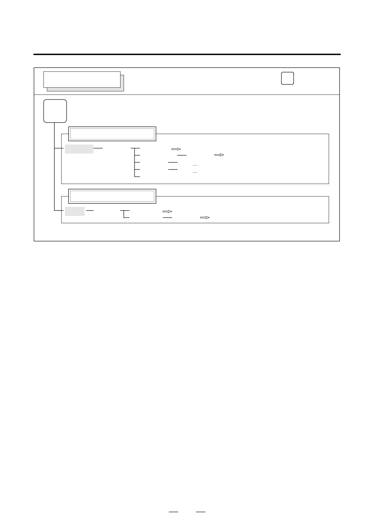
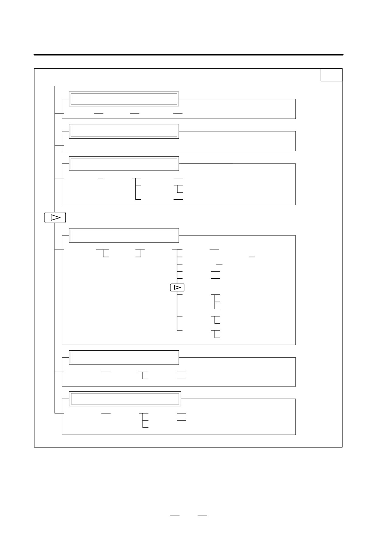
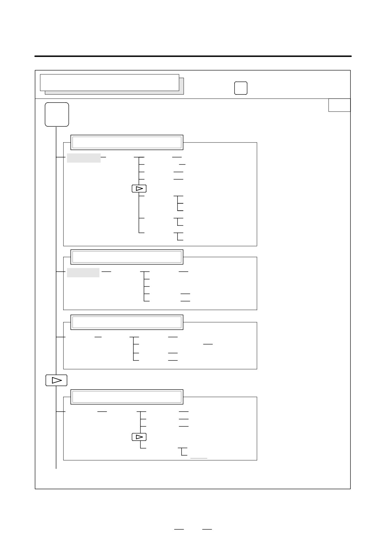
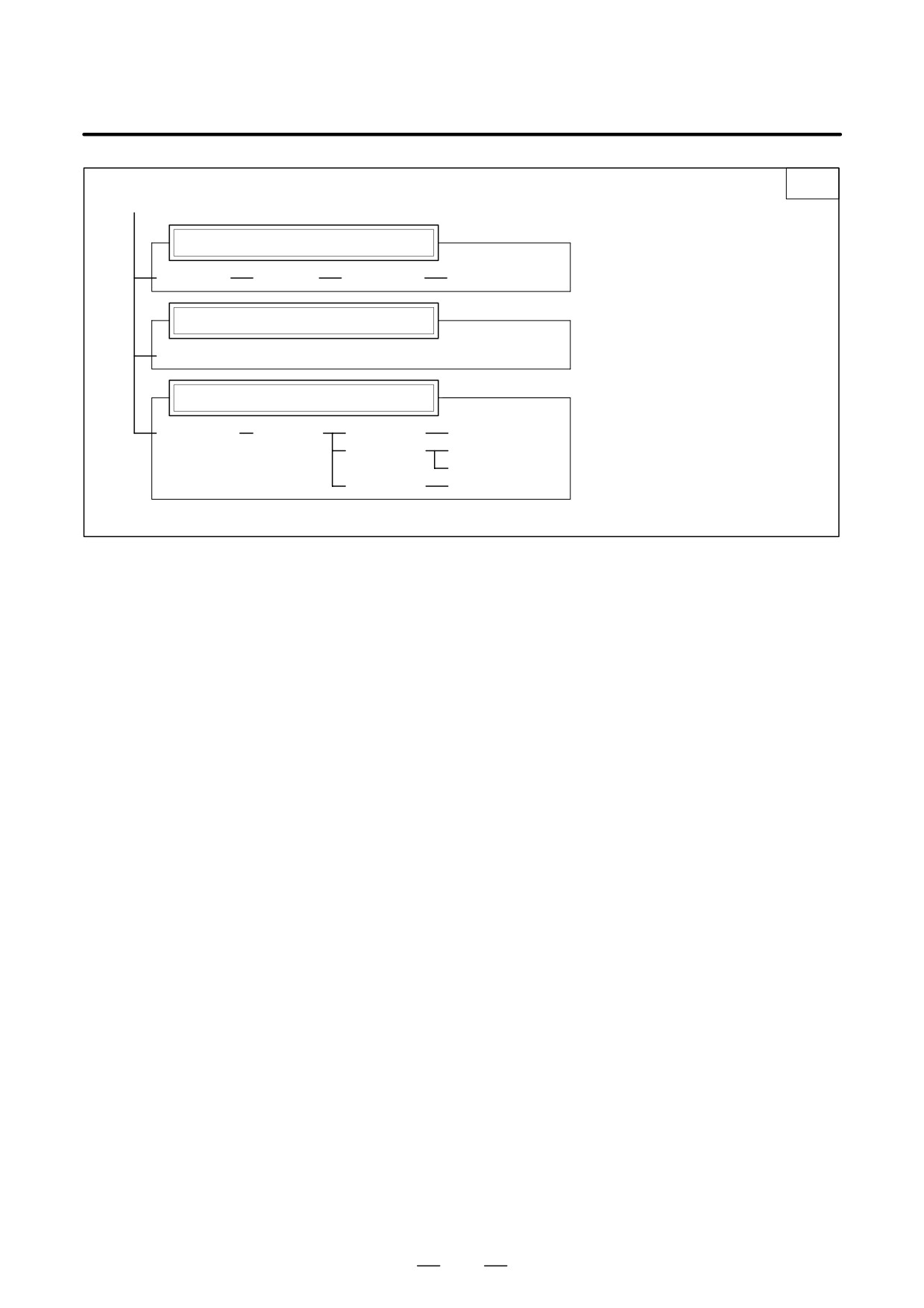
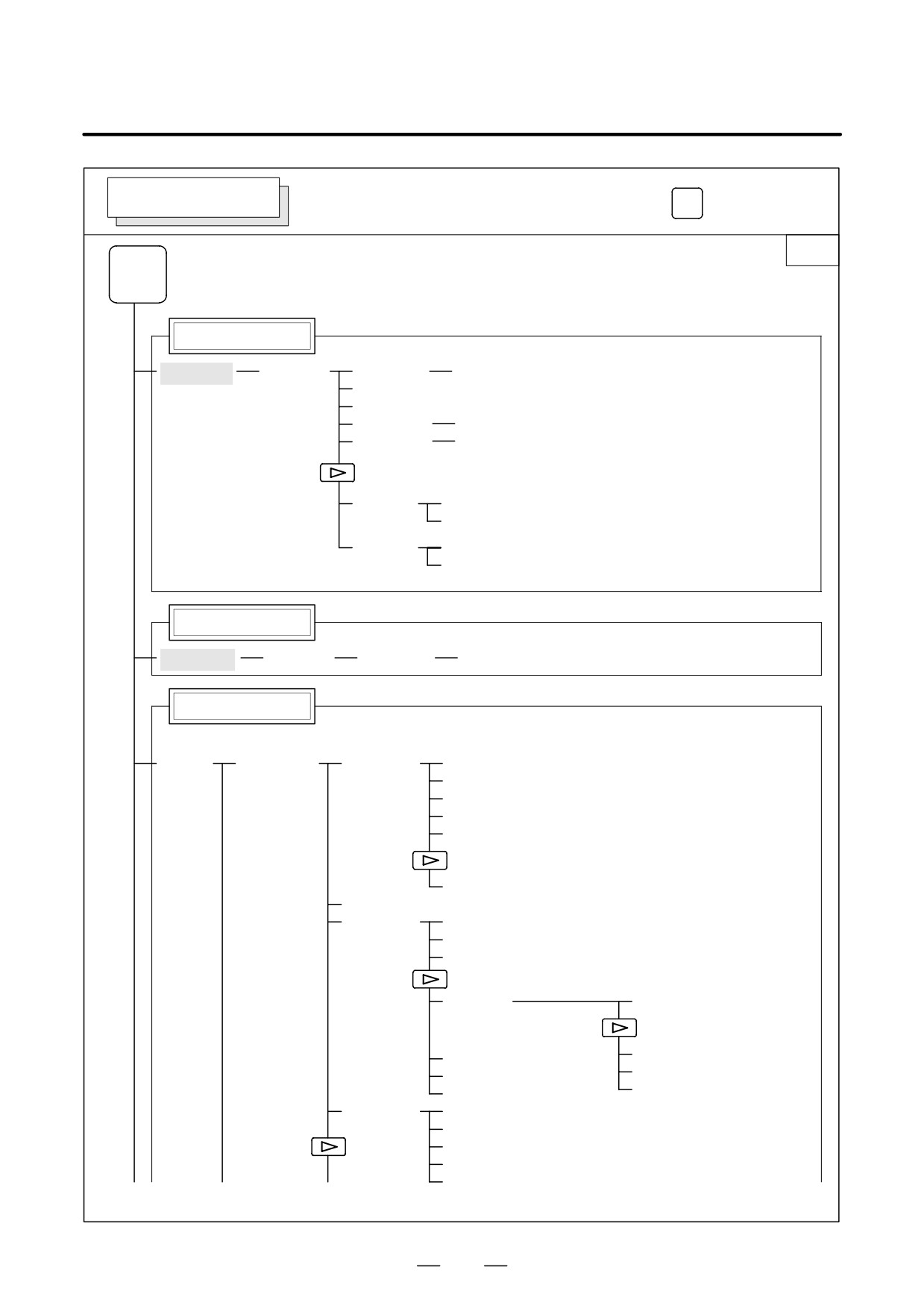
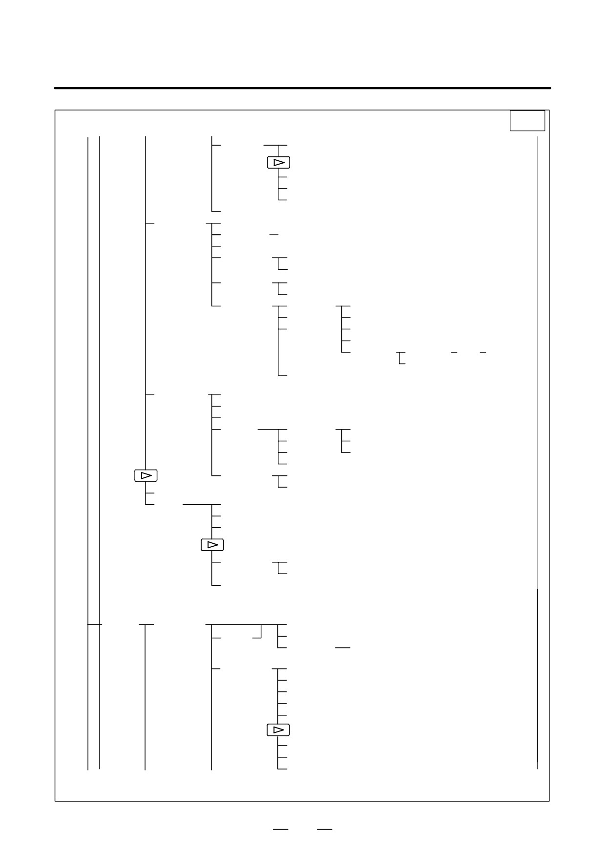
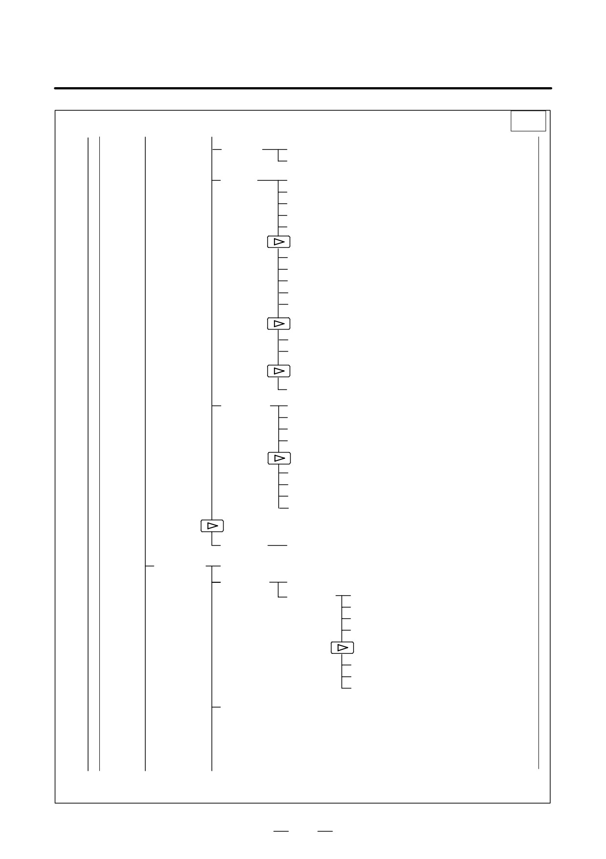
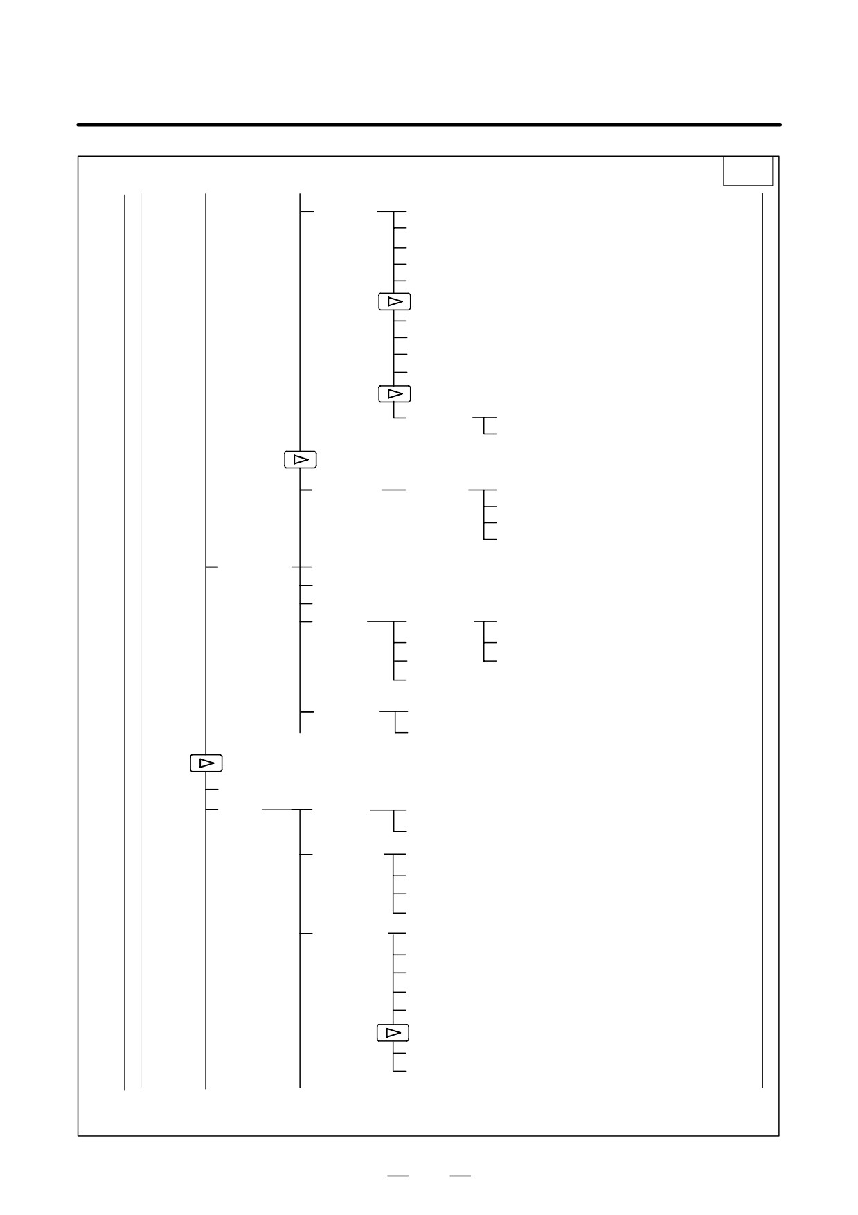
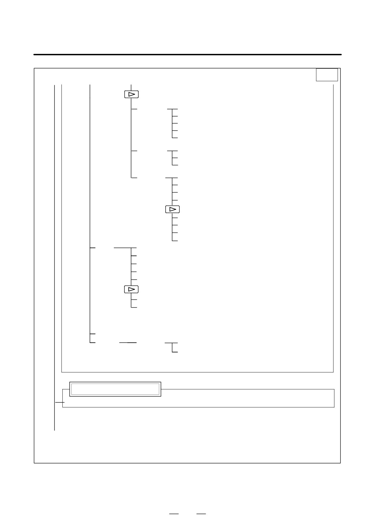
Soft key transition triggered by the function key
PROG
PROGRAM SCREEN
in the TJOG or THDL mode
PROG
Program input screen
[PRGRM]
[(OPRT)]
[BG-EDT]
See “When the soft key [BG-EDT] is pressed”
(O number)
[O SRH]
Return to the program
(Address)
[SRH↓]
(Address)
[SRH↑]
[REWIND]
Program directory display
[LIB]
[(OPRT)]
[BG-EDT]
See “When the soft key [BG-EDT] is pressed”
(O number)
[O SRH]
Return to the program
10
B-64115EN/02
1. DISPLAY AND OPERATION
PROG
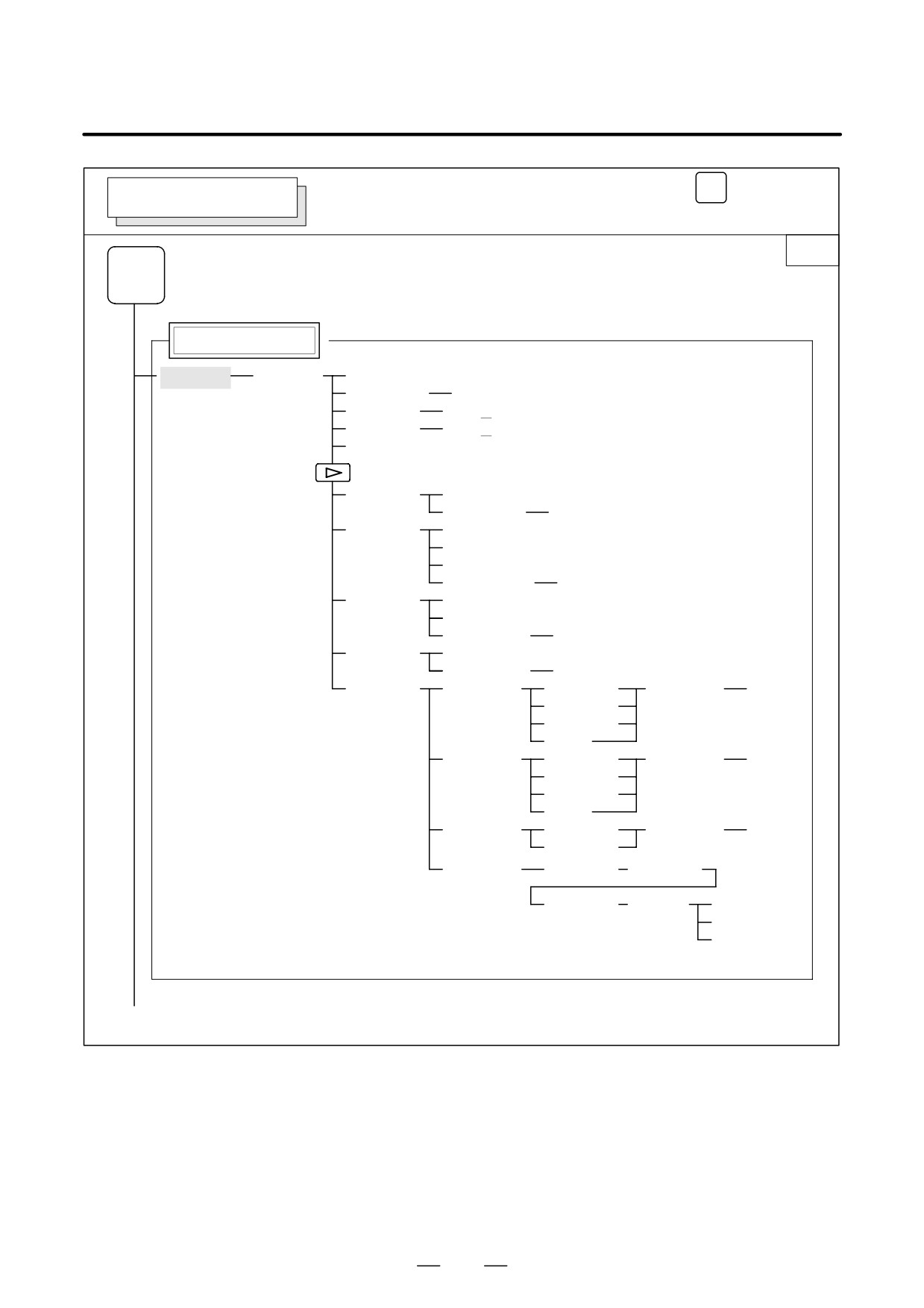
Soft key transition triggered by the function key
PROGRAM SCREEN
(When the soft key [BG-EDT] is pressed in all modes)
1/2
PROG
Program display
[PRGRM]
[(OPRT)]
[BG-END]
(O number)
[O SRH]
(Address)
[SRH↓]
(Address)
[SRH↑]
[REWIND]
[F SRH]
[CAN]
(N number)
[EXEC]
[READ]
[CHAIN]
(The cursor moves to the end of a program.)
[STOP]
[CAN]
(O number)
[EXEC]
[PUNCH]
[STOP]
[CAN]
(O number)
[EXEC]
[DELETE]
[CAN]
(N number)
[EXEC]
[EX-EDT]
[COPY]
[CRSR∼]
(O number)
[EXEC]
[∼CRSR]
[∼BTTM]
[ALL]
[MOVE]
[CRSR∼]
(O number)
[EXEC]
[∼CRSR]
[∼BTTM]
[ALL]
[MERGE]
[∼CRSR]
(O number)
[EXEC]
[∼BTTM]
[CHANGE]
(Address)
[BEFORE]
(Address)
[AFTER]
[SKIP]
[1-EXEC]
[EXEC]
(1)(Continued on the next page)
11
1. DISPLAY AND OPERATION
B-64115EN/02
2/2
(1)
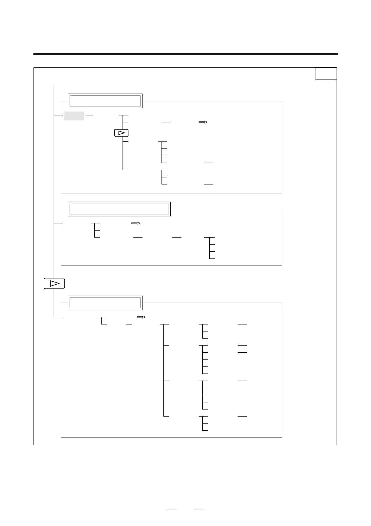
Program directory display
[LIB]
[(OPRT)]
[BG-EDT]
(O number)
[O SRH]
Return to the program
[READ]
[CHAIN]
[STOP]
[CAN]
(O number)
[EXEC]
[PUNCH]
[STOP]
[CAN]
(O number)
[EXEC]
Graphic Conversational Programming
[C.A.P.]
[PRGRM]
Return to the program
[G.MENU]
(G number)
[BLOCK]
(Data)
[LINE]
[CHAMF]
When a G number is omitted, the standard
screen appears.
[CNR.R]
[INPUT]
Floppy directory display
[FLOPPY]
[PRGRM]
Return to the program
[DIR]
[(OPRT)]
[F SRH]
(Numeral)
[F SET]
[CAN]
[EXEC]
[READ]
(Numeral)
[F SET]
(Numeral)
[O SET]
[STOP]
[CAN]
[EXEC]
[PUNCH]
(Numeral)
[F SET]
(Numeral)
[O SET]
[STOP]
[CAN]
[EXEC]
[DELETE]
(Numeral)
[F SET]
[CAN]
[EXEC]
12
B-64115EN/02
1. DISPLAY AND OPERATION
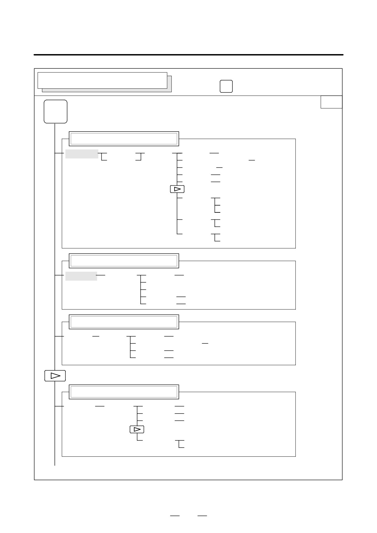
Soft key transition triggered by the
OFFSET/SETTING SCREEN (T series)
function key
OFFSET
SETTING
1/2
OFFSET
SETTING
Tool offset screen
[OFFSET]
[WEAR]
[(OPRT)]
(Number)
[NO SRH]
[GEOM]
(Axis name and numeral)
[MEASUR]
(Axis name)
[INP.C.]
(Numeral)
[+INPUT]
(Numeral)
[INPUT]
[CLEAR]
[ALL]
[WEAR]
[GEOM]
[READ]
[CAN]
[EXEC]
[PUNCH]
[CAN]
[EXEC]
Setting screen
[SETING]
[(OPRT)]
(Number)
[NO SRH]
[ON:1]
[OFF:0]
(Numeral)
[+INPUT]
(Numeral)
[INPUT]
Workpiece coordinate system setting screen
[WORK]
[(OPRT)]
(Number)
[NO SRH]
(Axis name and numeral)
[MEASUR]
(Numeral)
[+INPUT]
(Numeral)
[INPUT]
Macro variables display screen
[MACRO]
[(OPRT)]
(Number)
[NO SRH]
(Axis name)
[INP.C.]
(Numeral)
[INPUT]
[PUNCH]
[CAN]
[EXEC]
(1)(Continued on the next page)
13
1. DISPLAY AND OPERATION
B-64115EN/02
2/2
(1)
Pattern data input screen
[MENU]
[(OPRT)]
(Number)
[SELECT]
Software operator’s panel screen
[OPR]
Tool life management setting screen
[TOOLLF]
[(OPRT)]
(Number)
[NO SRH]
[CLEAR]
[CAN]
[EXEC]
(Numeral)
[INPUT]
Y-axis tool offset screen
[OFST
.2]
[WEAR]
[(OPRT)]
(Number)
[NO SRH]
[GEOM]
(Axis name and numeral)
[MEASUR]
(Axis name)
[INP.C.]
(Numeral)
[+INPUT]
(Numeral)
[INPUT]
[CLEAR]
[ALL]
[WEAR]
[GEOM]
[READ]
[CAN]
[EXEC]
[PUNCH]
[CAN]
[EXEC]
Workpiece shift screen
[WK.SHFT]
[(OPRT)]
(Numeral)
[+INPUT]
(Numeral)
[INPUT]
Chuck/tailstock barrier setting screen
[BARRIER]
[(OPRT)]
(Numeral)
[INPUT]
(Numeral)
[+INPUT]
[SET]
14
B-64115EN/02
1. DISPLAY AND OPERATION
Soft key transition triggered by the
OFFSET/SETTING SCREEN (M series)
function key
OFFSET
SETTING
1/2
OFFSET
SETTING
Tool offset screen
[OFFSET]
[(OPRT)]
(Number)
[NO SRH]
(Axis name)
[INP.C.]
(Numeral)
[+INPUT]
(Numeral)
[INPUT]
[CLEAR]
[ALL]
[WEAR]
[GEOM]
[READ]
[CAN]
[EXEC]
[PUNCH]
[CAN]
[EXEC]
Setting screen
[SETING]
[(OPRT)]
(Number)
[NO SRH]
[ON:1]
[OFF:0]
(Numeral)
[+INPUT]
(Numeral)
[INPUT]
Workpiece coordinate system setting screen
[WORK]
[(OPRT)]
(Number)
[NO SRH]
(Axis name and numeral)
[MEASUR]
(Numeral)
[+INPUT]
(Numeral)
[INPUT]
Macro variables display screen
[MACRO]
[(OPRT)]
(Number)
[NO SRH]
(Axis name)
[INP.C.]
(Numeral)
[INPUT]
[PUNCH]
[CAN]
[EXEC]
(1)(Continued on the next page)
15
1. DISPLAY AND OPERATION
B-64115EN/02
2/2
(1)
Patten data input screen
[MENU]
[(OPRT)]
(Number)
[SELECT]
Software operator’s panel screen
[OPR]
Tool life management setting screen
[TOOLLF]
[(OPRT)]
(Number)
[NO SRH]
[CLEAR]
[CAN]
[EXEC]
(Numeral)
[INPUT]
16
B-64115EN/02
1. DISPLAY AND OPERATION
SYSTEM SCREEN
Soft key transition triggered by the function key
SYSTEM
1/3
SYSTEM
Parameter screen
[PARAM]
[(OPRT)]
(Number)
[NO SRH]
[ON:1]
[OFF:0]
(Numeral)
[+INPUT]
(Numeral)
[INPUT]
[READ]
[CAN]
[EXEC]
[PUNCH]
[CAN]
[EXEC]
Diagnosis screen
[DGNOS]
[(OPRT)]
(Number)
[NO SRH]
PMC screen
<In the case of PMC-SA1>
[PMC]
[PMCLAD]
[SEARCH]
[TOP]
[BOTTOM]
[SRCH]
[W-SRCH]
[N-SRCH]
[F-SRCH]
[ADRESS]/[SYMBOL]
[TRIGER]
[TRGON]
[TRGOFF]
[START]
[DUMP]
[SEARCH]
[BYTE]
[DPARA]/[NDPARA]
[WORD]
[TRGSRC]
[INIT]
[D.WORD]
[WINDOW]
[DIVIDE]
[CANCEL]
[DELETE]
[SELECT]
[WIDTH]
(1)
(2)
(3)
(Continued on the next page)
17
1. DISPLAY AND OPERATION
B-64115EN/02
2/7
(1)
(2)
(3)
[DUMP]
[SEARCH]
[BYTE]
[WORD]
[D.WORD]
[DRARA]/[NDPARA]
[PMCDGN]
[TITLE]
[STATUS]
[SEARCH]
[ALARM]
[TRACE]
[T.DISP]/[TRCPRM]
[EXEC]
[M.SRCH]
[SEARCH]
[INPUT]
[ANALYS]
[SCOPE]
[SGNPRM]
[DELETE]
[START]/[STOP]
[INIT]
[T-SRCH]
[ADRESS]/[SYMBOL]
[EXCHG]
[SELECT]
[TO]
[EXEC]
[CANCEL]
[ADRESS]/[SYMBOL]
[PMCPRM]
[TIMER]
[COUNTR]
[KEEPRL]
[DATA]
[G.DATA]
[C.DATA]
[G.CONT]
[G-SRCH]
[NO.SRH]
[SEARCH]
[INIT]
[SETTING]
[YES]/[MANUAL]/[ROM]
[NO]/[AUTO]/[RAM]
[STOP]/[RUN]
[I/O]
[EXEC]
[CANCEL]
(No.)
[SPEED]
[INPUT]
[INIT]
[MDI]/[ROM]
<In the case of PMC-SB7>
[PMC]
[PMCLAD]
[ZOOM]
[LIST]
[SEARCH]
[SETING]
[INIT]
[SEARCH]
[TOPBTM]
[SEARCH]
[W-SRCH]
[F-SRCH]
[PICKUP]
[PREV]
[NEXT]
[GLOBAL]
(4)
(5)
(6)
(Continued on the next page)
18
B-64115EN/02
1. DISPLAY AND OPERATION
3/7
(4)
(5)
(6)
[TABLE]
[NOSRCH]
[V.SRCH]
[EDIT]
[LIST]
[SEARCH]
[CREATE]
[MODIFY]
[UPDATE]
[SELECT]
[DELETE]
[CUT]
[COPY]
[PASTE]
[RESTOR]
[SETING]
[STOP]
[SWITCH]
[LIST]
[PICKUP]
[JUMP]
[SWITCH]
[ERACE]
[ERSALL]
[TABLE]
[SETING]
[SETING]
[INIT]
[PMCDGN]
[TITLE]
[STATUS]
[SEARCH]
[FORCE]
[SEARCH]
[ON]
[OFF]
[STATUS]
[OVRSET]
[OVRRST]
[INIT]
[ALARM]
(7)
(8)
(9)
(Continued on the next page)
19
1. DISPLAY AND OPERATION
B-64115EN/02
4/7
(7)
(8)
(9)
[TRACE]
[START]
[<<PREV]
[NEXT>>]
[MARK]
[SETING]
[Z.IN]
[Z.OUT]
[MV.UP]
[MV.DWN]
[PUNCH]
[EXEC]
[CANCEL]
[I/OCHK]
[IOLNK]
[PRV.PG]
[NXT.PG]
[PRV.CH]
[NXT.CH]
[PMCPRM]
[TIMER]
[COUNTR]
[KEEPRL]
[DATA]
[G.DATA]
[C.DATA]
[G.CONT]
[G-SRCH]
[NO.SRH]
[SEARCH]
[INIT]
[SETING]
[PREV]
[NEXT]
[RUN] / [STOP]
[EDIT]
[TITLE]
[INSERT]
[DELETE]
[SYMBOL]
[INPMOD]
[DELETE]
[SRCH]
[COPY]
[MESSAGE]
[INPMOD]
[DELETE]
[SRCH]
[COPY]
[DSPMOD]
[ETC]
[D.CHAR]
(10)
(11)
(12)
(Continued on the next page)
20
B-64115EN/02
1. DISPLAY AND OPERATION
5/7
(10)
(11)
(12)
[MODULE]
[INPUT]
[SEARCH]
[DELETE]
[PRV.CH]
[NXT.CH]
[CROSS]
[CRSREF]
[INPUT]
[INIT]
[CLEAR]
[CLRTTL]
[CLRLAD]
[CLRSYM]
[CLRMSG]
[CLRALL]
[CLRMDL]
[CONDNS]
[CLRPRM]
[I/O]
[EXEC]
[CANCEL]
[M-CARD]
[F-ROM]
[FDCAS]
[OTHERS]
[SPEED]
[SYSPRM]
[MONIT]
[ONLINE]
[EMG ST]
[INIT]
System configuration screen
[SYSTEM]
(13)
(Continued on the next page)
21
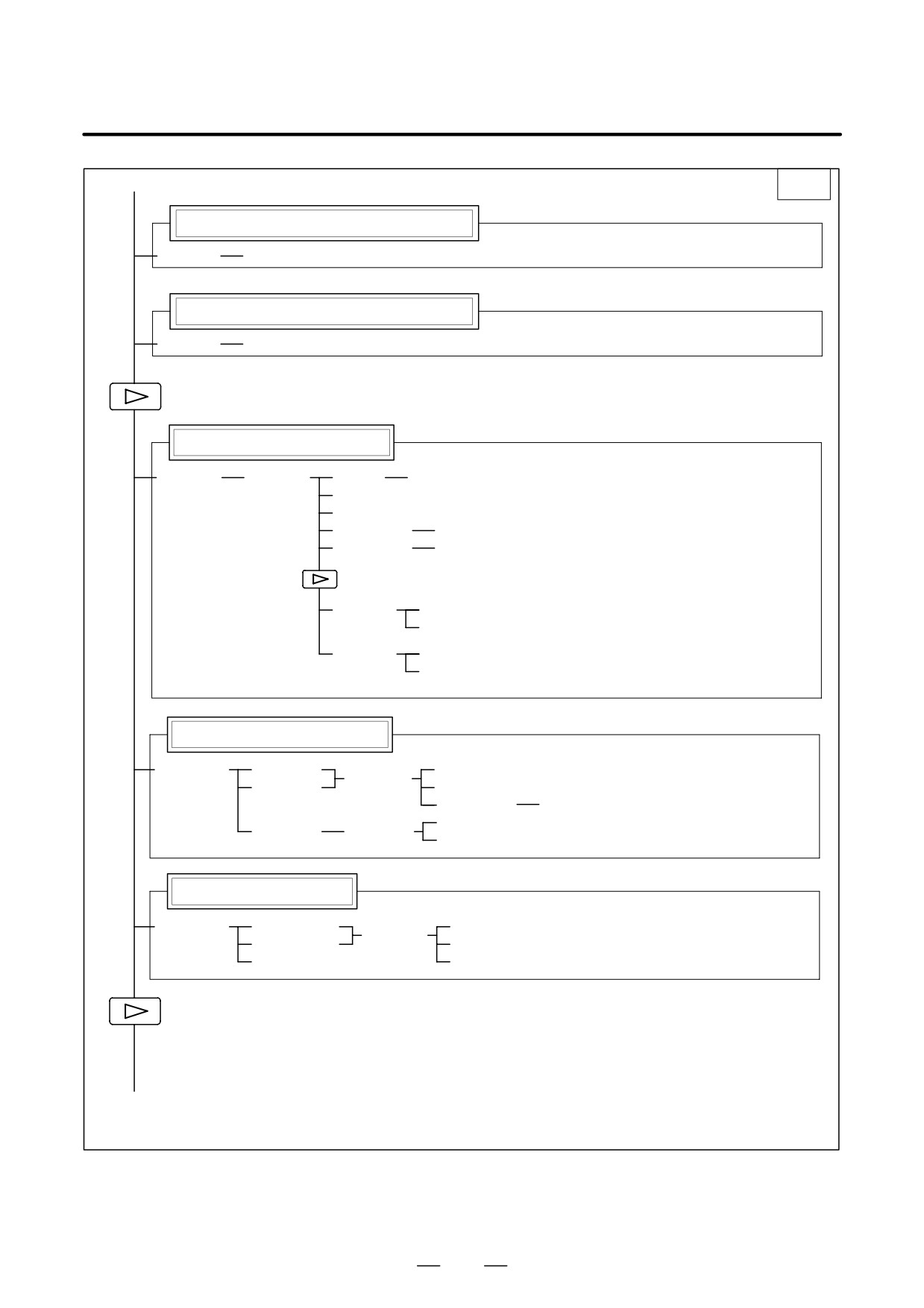
1. DISPLAY AND OPERATION
B-64115EN/02
(13)
6/7
ID information screen: αi servo information screen
[SYSTEM]
[SV-INF]
ID information screen: αi spindle information screen
[SYSTEM]
[SP-INF]
Pitch error compensation screen
[PITCH]
[(OPRT)]
(No.)
[NO SRH]
[ON:1]
[OFF:0]
(Numeral)
[+INPUT]
(Numeral)
[INPUT]
[READ]
[CAN]
[EXEC]
[PUNCH]
[CAN]
[EXEC]
Servo parameter screen
[SV.PRM]
[SV.SET]
[ON:1]
[(OPRT)]
[SV.TUN]
[OFF:0]
(Numeral)
[INPUT]
[TRACE]
[SV.TRC]
[(OPRT)]
[TRNSF]
Spindle parameter screen
[SP.PRM]
[SP.SET]
[ON:1]
[(OPRT)]
[SP.TUN]
[OFF:0]
[SP.MON]
[INPUT]
(14)
(Continued on the next page)
22
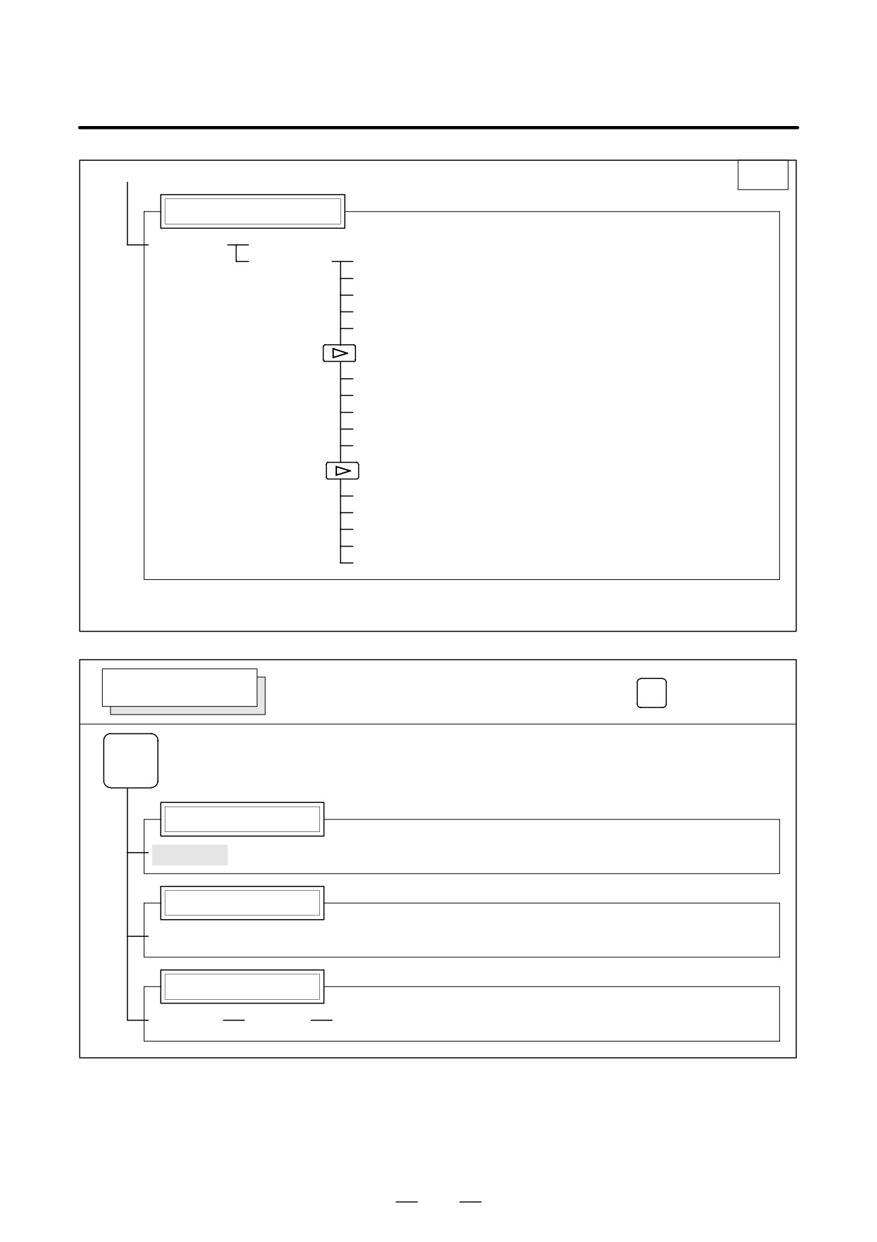
B-64115EN/02
1. DISPLAY AND OPERATION
(14)
7/7
Waveform diagnosis screen
[W.DGNS]
[W.PRM]
[W.GRPH]
[STSRT]
[TIME→]
[←TIME]
[H-DOBL]
[H-HALF]
[STSRT]
[CH-1↑]
[CH-1↓]
[V-DOBL]
[V-HALF]
[STSRT]
[CH-2↑]
[CH-2↓]
[V-DOBL]
[V-HALF]
MESSAGE SCREEN
Soft key transition triggered by the function key
MESSAGE
MESSAGE
Alarm display screen
[ALARM]
Message display screen
[MSG]
Alarm history screen
[HISTRY]
[(OPRT)]
[CLEAR]
23
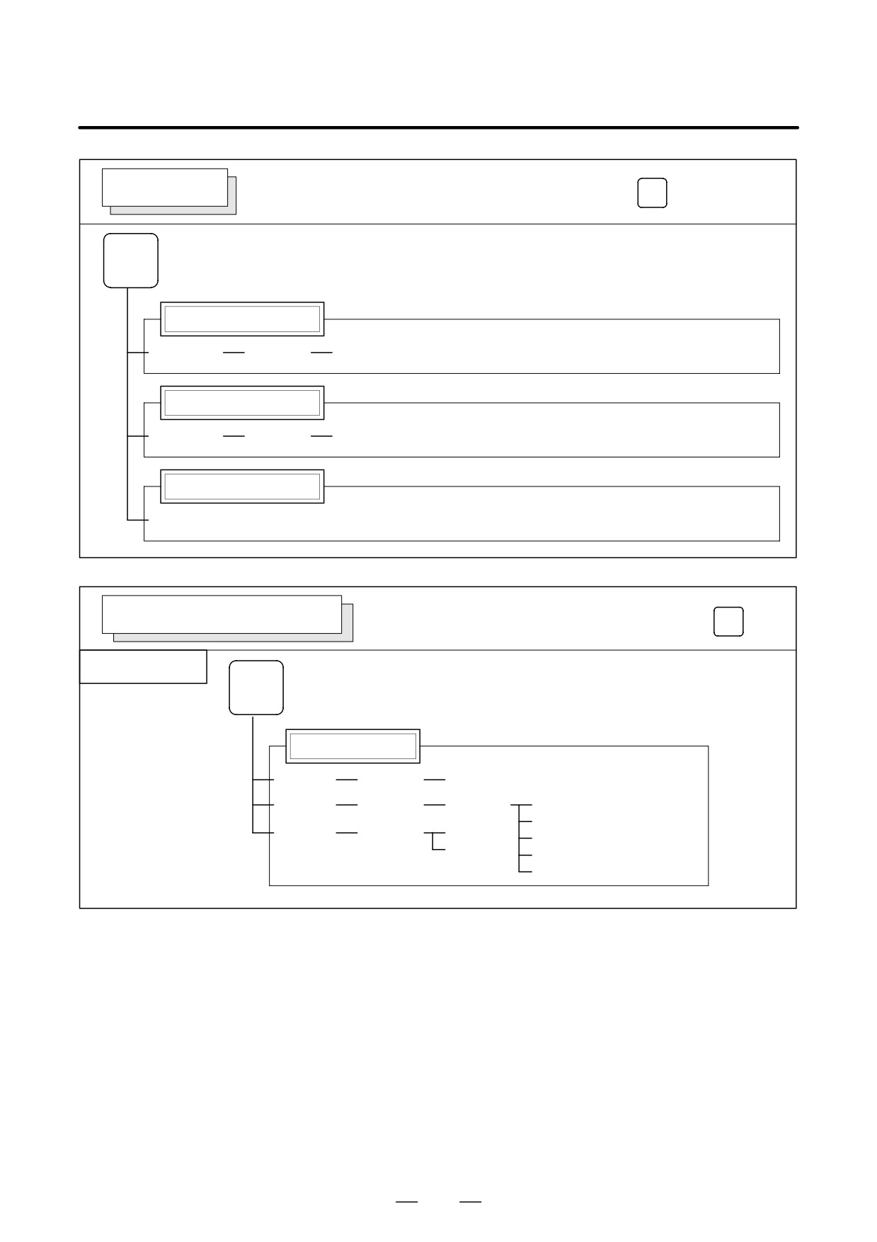
1. DISPLAY AND OPERATION
B-64115EN/02
HELP SCREEN
Soft key transition triggered by the function key
HELP
HELP
Alarm detail screen
[ALARM]
[(OPRT)]
[SELECT]
Operation method screen
[OPERAT]
[(OPRT)]
[SELECT]
Parameter table screen
[PARAM]
GRAPHIC SCREEN (T series)
Soft key transition triggered by the function key
GRAPH
Tool path graphics
GRAPH
Mode 0
Tool path graphics
[G.PRM]
[(OPRT)]
[NORMAL]
[GRAPH]
[(OPRT)]
[ZOOM]
[HEAD]
[ERASE]
[ZOOM]
[(OPRT)]
[ACT]
[PROCES]
[HI/LO]
[EXEC]
[STOP]
24
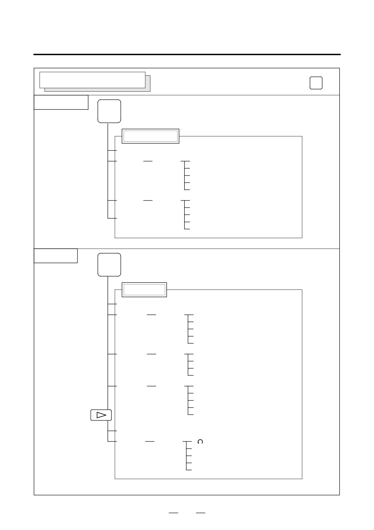
B-64115EN/02
1. DISPLAY AND OPERATION
GRAPHIC SCREEN (M series)
Soft key transition triggered by the function key
GRAPH
Tool path graphics
GRAPH
Tool path graphics
[PARAM]
[EXEC]
[(OPRT)]
[AUTO]
[STSRT]
[STOP]
[REWIND]
[CLEAR]
[ZOOM]
[(OPRT)]
[EXEC]
[←]
[→]
[POS]
[↑]
[↓]
Solid graphics
GRAPH
Solid graphics
[PARAM]
[BLANK]
[(OPRT)]
[ANEW]
[+ROT]
[-ROT]
[+TILT]
[-TILT]
[EXEC]
[(OPRT)]
[A.ST]]
[F.ST]
[STOP]
[REWIND]
[REVIEW]
[(OPRT)]
[ANEW]
[+ROT]
[-ROT]
[+TILT]
[-TILT]
[PARAM]
[3-PLN]
[(OPRT)]
[
]
[←]
[→]
[↑]
[↓]
25
1. DISPLAY AND OPERATION
B-64115EN/02
1.2
SCREEN DISPLAYED
IMMEDIATELY AFTER
POWER IS TURNED
ON
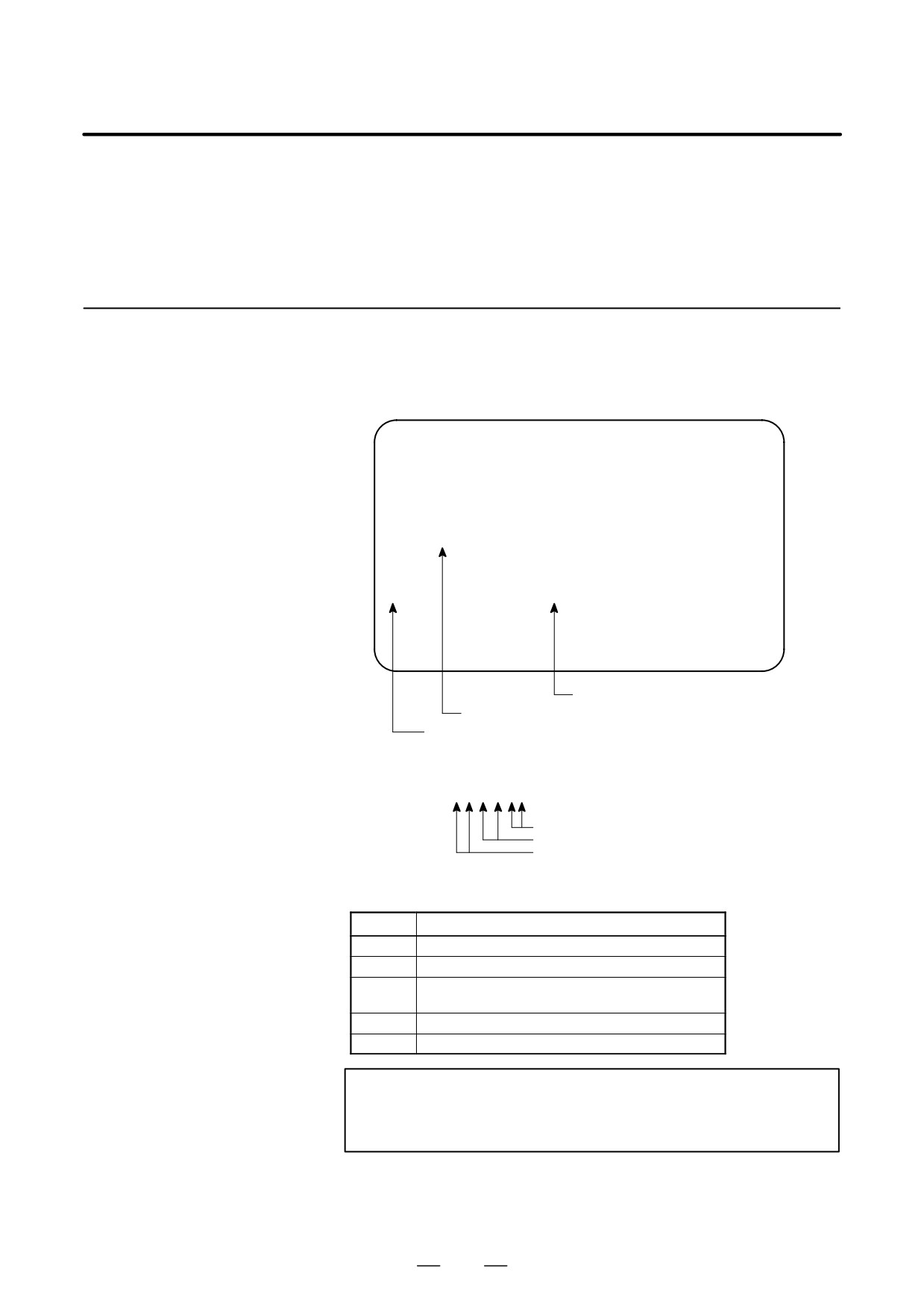
Types of PCBs mounted on the slots are displayed.
1.2.1
If a hardware trouble or an incorrect mounting is found, this screen is
Slot Status Display
displayed.
D Slot state screen
SLOT CONFIGURATION DISPLAY
0: 00184000
0:
1: E1AA5E08
1:
2: 008E6D01
2:
3:
3:
4:
4:
5:
5:
…
…
Physical slot number (2ndary side)
Module ID of the PCB mounted (*1)
Physical slot number (primary side)
*1) Module ID of PCB
ff j j ∆ ∆
Internal slot number
Module function (software ID)
Type of PCB (module ID)
D Module ID
ID
Name
18
Series 0i-C main CPU board
19
Series 0i Mate-C main CPU board
1A
Series 0i-C main CPU board
1B
1C
Series 0i Mate-C main CPU board
8E
Data server board, Fast Ethernet board
NOTE
See page p-2 in “PREFACE” for information about the basic
units.
D Software ID
40 : Main CPU
6D : Fast Ethernet, Data server
26
B-64115EN/02
1. DISPLAY AND OPERATION
1.2.2
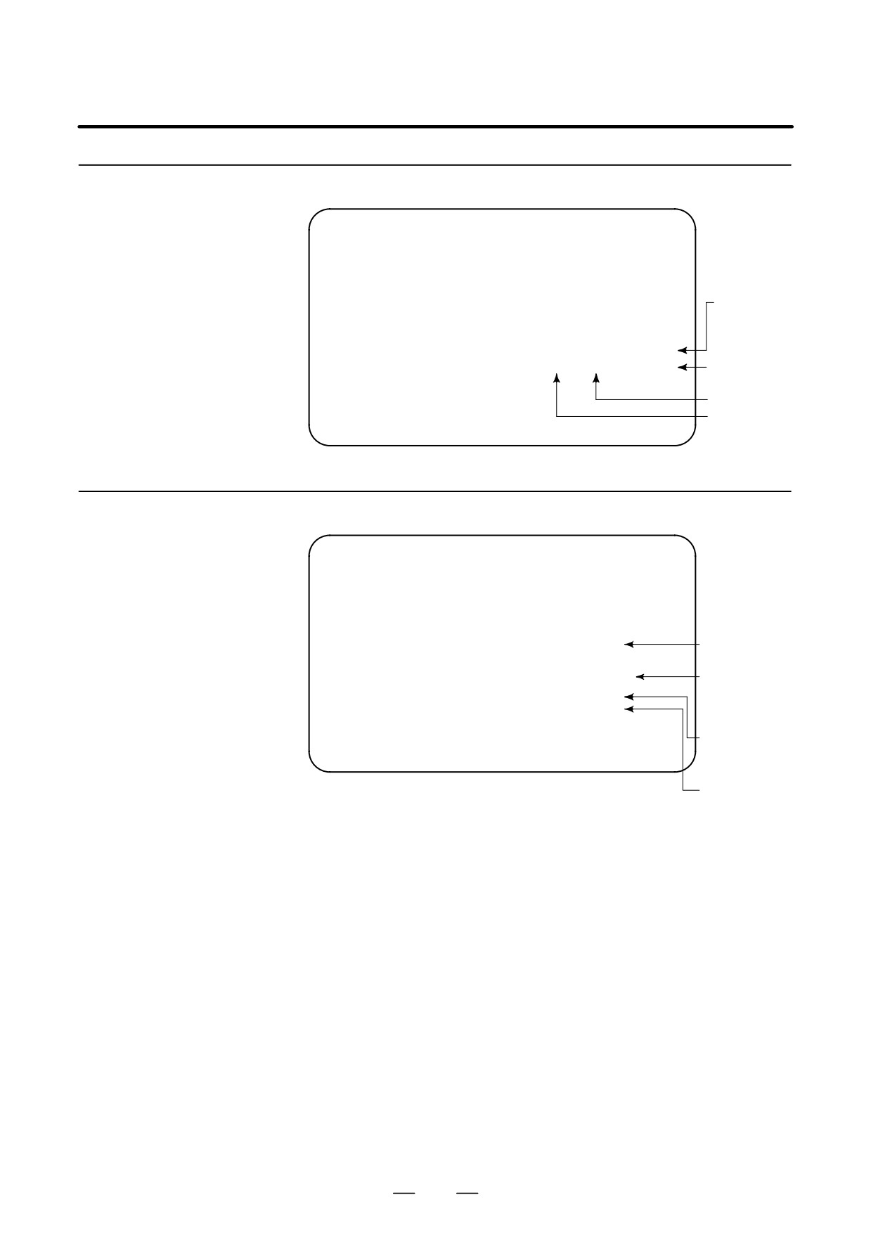
Setting Module Screen
END : Setting
completed
D4B1-01
COPYRIGHT FANUC LTD 2004-2004
SLOT 01 (E1AA) : END
Space :
SLOT 02 (008E) :
Setting incom-
pleted
Module ID
Slot number
1.2.3
Configuration Display
of Software
CNC control
D4B1-01
software
COPYRIGHT FANUC LTD 2004-2004
SERVO : 90B5-01
Digital servo
ROM
OMM : yyyy-yy
PMC : zzzz-zz
Order made
macro/macro
compiler
PMC
27
1. DISPLAY AND OPERATION
B-64115EN/02
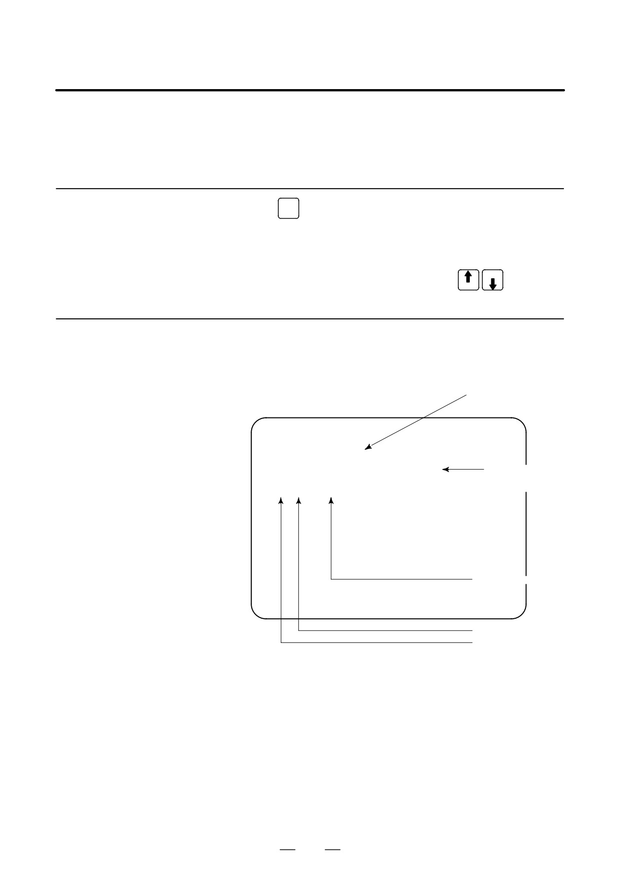
After the system has been installed correctly, you can find the PCBs
1.3
installed and the softwares integrated on the system configuration screen.
SYSTEM
CONFIGURATION
SCREEN
1.3.1
SYSTEM
(1) Press
key.
Display Method
(2) Press soft key [SYSTEM], then the system configuration screen is
displayed.
(3) The system configuration screen is composed of three screens and
PAGE
each of them can be selected by the page key
PAGE
1.3.2
Configuration of PCBs
D Screen
Software series of mod-
ule with CPU
SYSTEM CONFIG (SLOT)
PAGE01
SLOT MODULE ID SERIES VERSION
00 0018 : 40
D4B1
0001
Software version
of module with
01 F1AA : 5E
CPU
02 008E : 6D
656W
0001
Software ID (type)
Module ID
Slot No.
(80 to 8F is 2nd side)
28
B-64115EN/02
1. DISPLAY AND OPERATION
D Module ID
ID
Name
18
Series 0i-C main CPU board
19
Series 0i Mate-C main CPU board
1A
Series 0i-C main CPU board
1B
1C
Series 0i Mate-C main CPU board
8E
Data server board, Fast Ethernet board
NOTE
See page p-2 in “PREFACE” for information about the basic
units.
D Software ID
40 : Main CPU
6D : Fast Ethernet, Data server
1.3.3
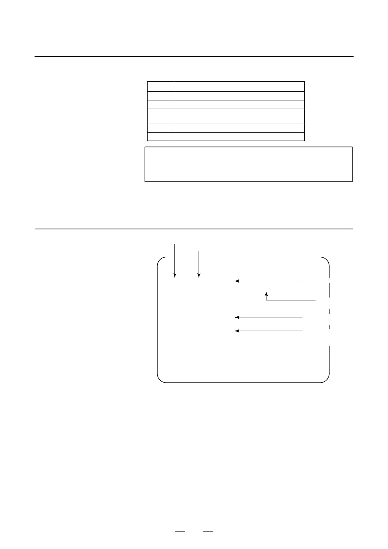
Kind of software
Software Configuration
Software series
Screen
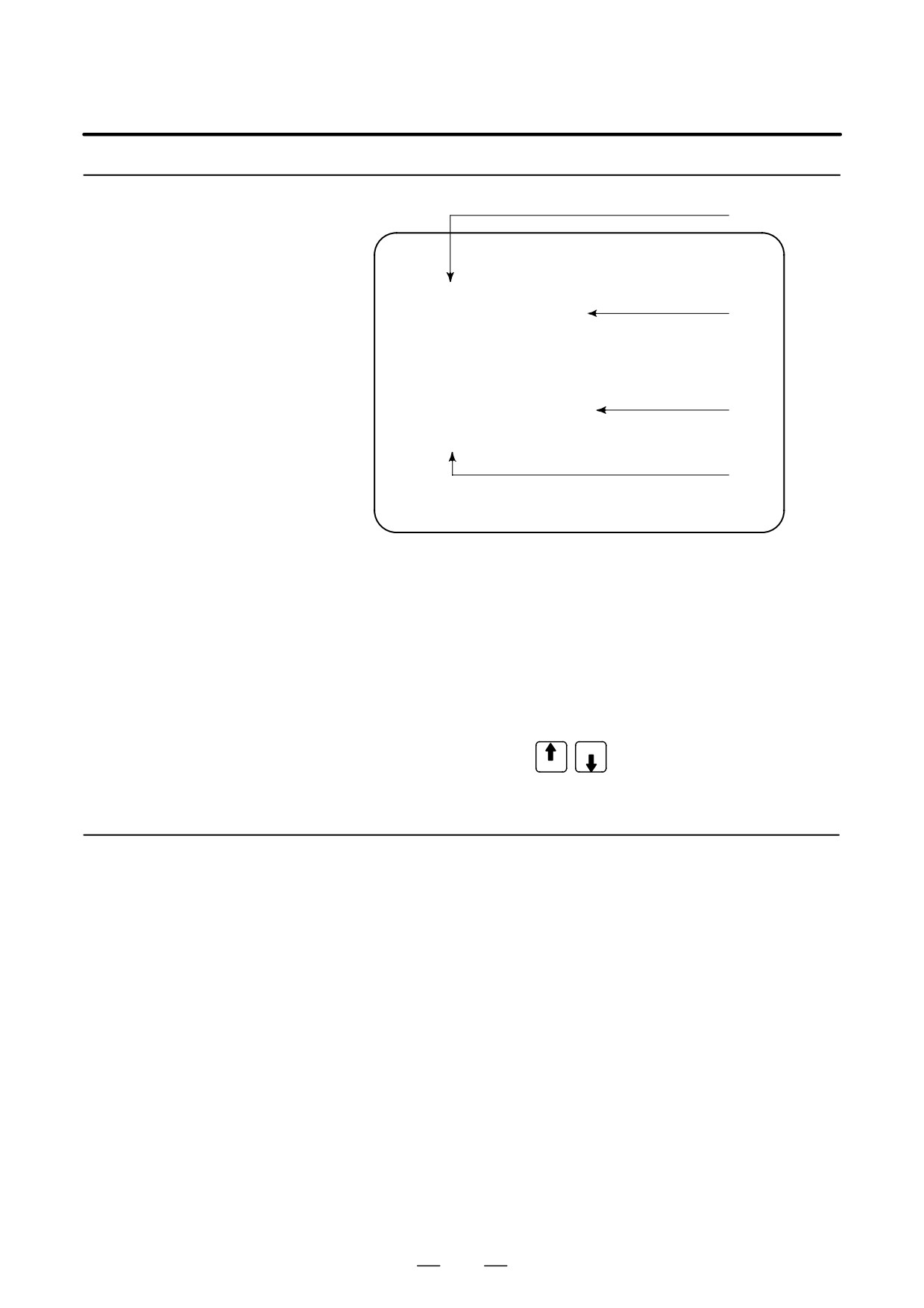
SYSTEM CONFIG
(SOFTWARE)
01234 N12345
PAGE:02
SYSTEM
D4B1
0001
Software version
BASIC+OPTION-A1+OPTION-A2+OPTION-A3+OPTION-A4
SERVO
9085
0001
Software
PMC(SYS)
408A
0001
configuration
408A
0001
PMC(LAD) FS16
0001
Character written
on PMC title screen
MACRO LIB BZG1
0001
MACRO APL AAAA
BBBB
Character written
on macro compiler
BOOT
60M5
0006
or on CAP.
GRAPHIC-1 60V5
0001
GRAPHIC-2 60V6
0001
MEM **** *** ***
12:14:59
[ PARMA ][ DGNOS ][ PMC ][ SYSTEM ][(OPRT)]
29
1. DISPLAY AND OPERATION
B-64115EN/02
1.3.4
Configuration of the modules displayed on PCB.
(1)
Module Configuration
Screen
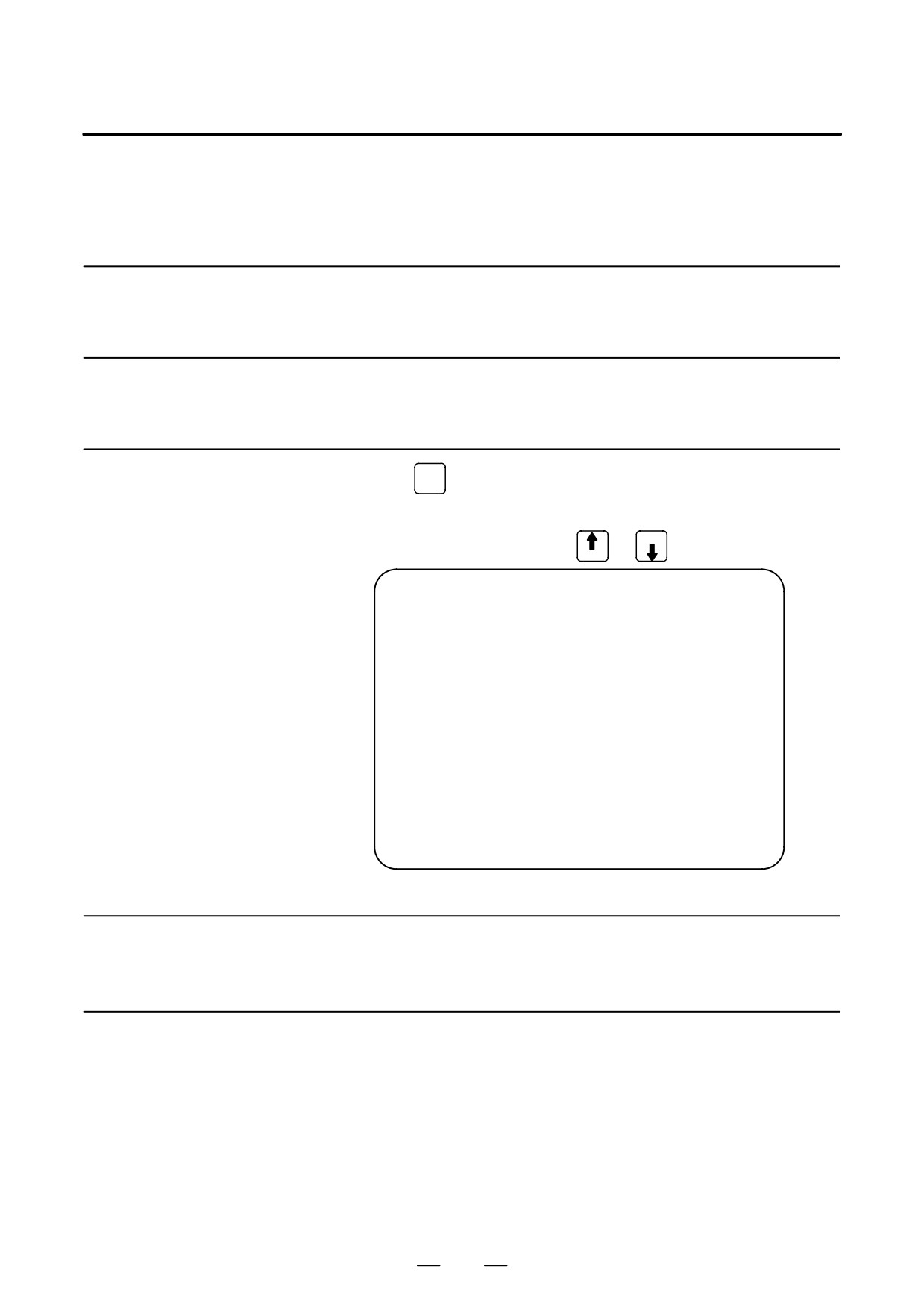
SYSTEM CONFIG
(MODULE)
01234 N12345
PAGE:03
SLOT
00
MOTHER BOARD
(2)
AXIS CTRL CARD
:
08
DISPLAY CTRL CARD :
0E
CPU CARD
:
11
FROM DIMM
:
C7
SRAM DIMM
:
05
(4)
DRAM DIMM
:
A9
PMC CPU
:
01
(3)
MEM **** *** ***
12:14:59
[ PARMA ][ DGNOS ][ PMC ][ SYSTEM ][(OPRT)]
Contents of display
(1) Slot number (The number is corresponding to PCB configuration
screen)
(2) Type of PCB mounted
(3) Name of card PCB or DIMM module
(4) Hardware ID of mounted card PCB or DIMM module
Refer to “2.5.3 Printed Circuit Boards of the Control Unit” for
correspondence with each hardware ID and drawing number.
PAGE
Pressing the PAGE key
displays the system configuration
PAGE
screen of other PCBs.
1.3.5
D αi series servo and αi series spindle
When the αi servo/αi spindle system is connected, ID information
ID Information Screen
owned by connected units (motor, amplifier, module, etc.) for αi
(αi Servo Information
servo/αi spindle can be displayed on the CNC screen.
Screen/αi Spindle
See below for details.
Information Screen)
D αi servo information screen (Chapter 6 Digital Servo)
D αi spindle information screen (Chapter 7 AC Spindle (Serial
Spindle))
30
B-64115EN/02
1. DISPLAY AND OPERATION
1.4
ALARM HISTORY
SCREEN
1.4.1
Alarm History
Screen
1.4.1.1
Alarms generated in the NC are recorded. The latest 50 alarms generated
are recorded. The 50th and former alarms are deleted.
General
1.4.1.2
MESSAGE
(1) Press
key .
Screen display
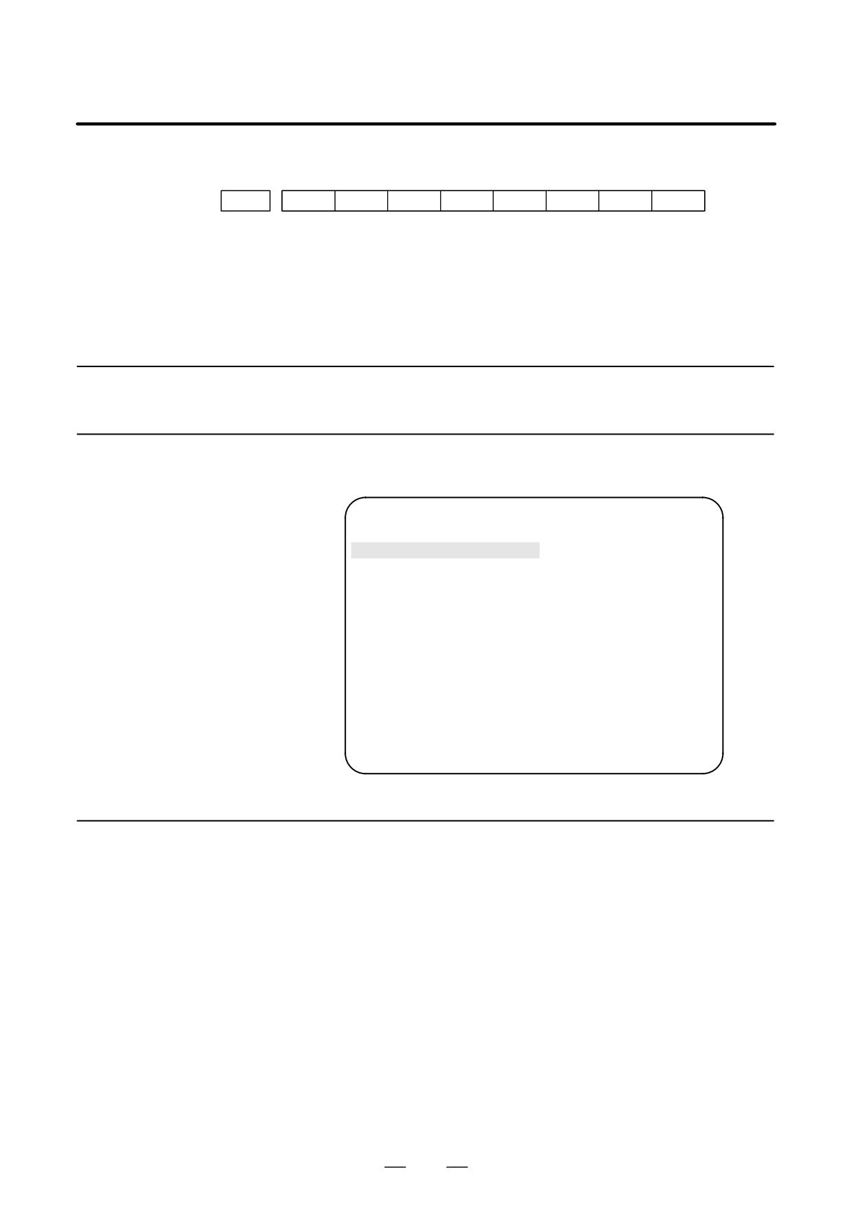
(2) Press soft key [HISTRY] and an alarm history screen is displayed.
PAGE
(3) Other pages are displayed by
or
key.
PAGE
ALARM HISTORY
O1234 N12345
02/04/18 20:56:26
506 OVERTRAVEL :
+X
02/04/18 19:58:11
000 TURN OFF POWER
02/04/18 19:52:45
000 TURN OFF POWER
02/04/18 19:48:43
300 APC ALARM
: X-AXIS ZERO RETURN REQUEST
02/04/18 18:10:10
507 OVERTRAVEL :
+B
[ ALARM ][ MSG ][ HISTRY ][
][(OPRT)]
(1) Press soft key [(OPRT)].
1.4.1.3
Clearing alarm history
(2) Press soft key [(CLEAR], then the alarm history is cleared.
1.4.1.4
When an external alarm (No. 1000 to 1999) or a macro alarm (No. 3000
to 3999) is output, the alarm history function can record both the alarm
Alarm display
number and message if so specified in the following parameter. If
recording of the message is not set or if no message is input, only an
external alarm or macro alarm is displayed.
31
1. DISPLAY AND OPERATION
B-64115EN/02
#7
#6
#5
#4
#3
#2
#1
#0
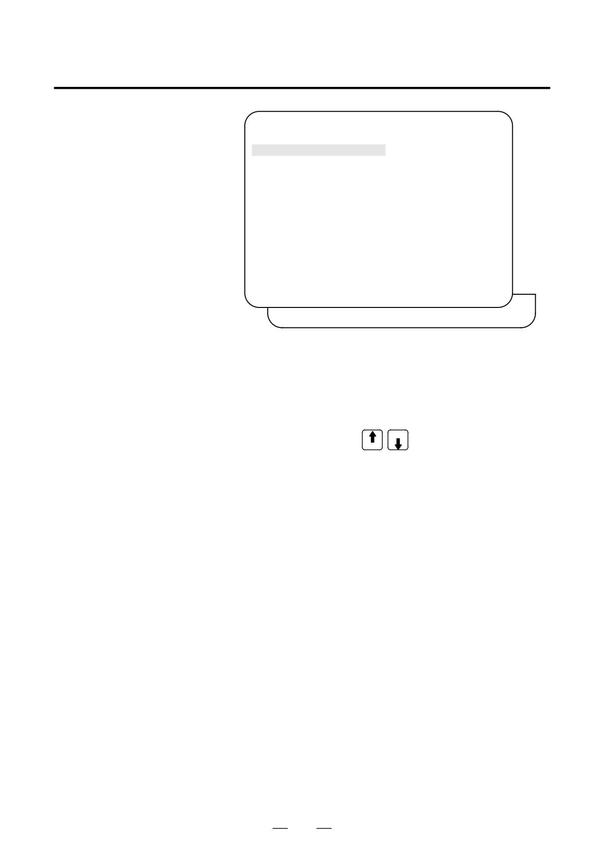
3112
EAH
[Data type] Bit
#3 (EAH) The alarm history function:
0 : Does not record the messages output with external alarms or macro
alarms.
1 : Records the messages output with external alarms or macro alarms.
1.4.2
System Alarm History
1.4.2.1
Up to three system alarms issued in the past are stored, and information
about those alarms can be displayed on the system alarm history screen.
General
SYSTEM ALARM HISTORY
O1234 N12345
1
2002-03-13 12:13:19
930
CPU INTERRUPT
2
2002-03-11 07:23:07
900
ROM PARITY
3
2002-02-27
973
NON MASK INTERRUPT
EDIT **** *** ***
08:20:52
[
][
][ NMIHIS ][
][
]
1.4.2.2
By setting bit 2 (NMH) of parameter No. 3103 to 1, information about up
to three system alarms including the latest system alarm can be displayed.
System alarm history
The latest system alarm information is displayed at the top of the list, and
screen (history list
a lower item in the list indicates older system alarm information.
screen)
Procedure
1
Set bit 2 (NMH) of parameter No. 3103 to 1.
2
Press the function key <MESSAGE>.
3
Press the [NMIHIS] chapter selection soft key.
The following information is displayed:
1. System alarm occurrence date and time
2. System alarm number
3. System alarm message (No message is displayed for some
system alarms.)
32
B-64115EN/02
1. DISPLAY AND OPERATION
SYSTEM ALARM HISTORY
O1234 N12345
1
2002-03-13 12:13:19
930
CPU INTERRUPT
2
2002-03-11 07:23:07
900
ROM PARITY
3
2002-02-27
973
NON MASK INTERRUPT
EDIT **** *** ***
08:20:52
[
][
][ NMIHIS ][
][
]
[ SELECT ][ RETURN ][ CLEAR ][
][
]
[SELECT] soft key
This soft key displays the details of a system alarm.
Procedure
1
Press the [(OPRT)] soft key on the system configuration screen.
PAGE
2
By using the cursor keys
, move the cursor to the system
PAGE
alarm number whose details are to be displayed.
3
Press the
[SELECT] soft key.
4
The details of the selected system alarm are displayed.
[CLEAR] soft key
This soft key clears all system alarm information stored.
When bit 4 (OPC) of parameter No. 3110 is set to 1, this soft key is
displayed. When bit 4 (OPC) of parameter No. 3110 is set to 0, this soft
key is not displayed.
Procedure
1
Set bit 4 (OPC) of parameter No. 3110 to 1.
2
Press the [(OPRT)] soft key on the system configuration screen.
3
Press the [CLEAR] soft key.
4
Information about all of the three system alarms stored is cleared.
[RETURN] soft key
Pressing the [RETURN] soft key while system alarm history screen
(detail screen) is displayed returns the screen display to the system alarm
list screen.
33
1. DISPLAY AND OPERATION
B-64115EN/02
1.4.2.3
The system alarm history screen (detail screen) displays information
items such as registers and stacks involved when a system alarm is issued.
System alarm history
screen (detail screen)
The following items are displayed:
1. System alarm occurrence date and time
2. System alarm number
3. System alarm message (No message is displayed for some system
alarms.)
4. System alarm occurrence series and edition
5. Number of display pages
6. General-purpose resistor, pointer index register, segment register,
task register, LDT register, flag register, interrupt source, error
code, error address
7. Contents of stacks (up to 32 stacks)
8. Contents of stacks of privilege level 3 (up to 48 stacks)
9. NMI information
You can switch among the information items 6 to 9 by the page keys
PAGE
PAGE
Pressing the [RETURN] soft key returns the screen display to the state
alarm history list screen.
SYSTEM ALARM HISTORY
O1234 N12345
2
2002-03-11 07:23:07
D4B1-01(1/4)
973 NON MASK INTERRUPT
EAX
EBX
ECX
EDX
00000000
00930063
000003E0
00000040
ESI
EDI
EBP
ESP
00000010
009404E0
0000FFB4
0000FFDC
SS
DS
ES
FS
GS
TR
LDTR
06D8 0338 0248 0440 0338 0628 0028
EFLAGS
VECT
ERRC
ERROR-ADDRESS
00003046
FFFF
0000
03E0:000009BC
EDIT **** *** ***
08:20:52
[ SELECT ][ RETURN ][ CLEAR ][
][
]
(Detail display screen 1)
34
B-64115EN/02
1. DISPLAY AND OPERATION
SYSTEM ALARM HISTORY
O1234 N12345
2
2002-03-11 07:23:07
D4B1-01(2/4)
973 NON MASK INTERRUPT
STACK
(PL0)
3646 0338 7CBA 0001 0958 FFF8 0068 0063
0346 0000 0000 02BC 08F8 52F1 2438 0338
0580 0440 0580 001F 03C0 0214 0780 0FFF
0000 0000 0000 0000 0000 0000 0000 0000
EDIT **** *** ***
08:20:52
[ SELECT ][ RETURN ][ CLEAR ][
][
]
(Detail display screen 2)
SYSTEM ALARM HISTORY
O1234 N12345
2
2002-03-11 07:23:07
D4B1-01(3/4)
973 NON MASK INTERRUPT
STACK!(PL3)
SS:ESP3 =0804:00007C50
CS:EIP =1350:00001234
1008 1408 0001 0002 0003 0004 1008 FFE4
1008 3678 00FA 0024 0000 0000 0000 0000
0000 0000 0000 0000 0000 0000 0000 0000
0000 0000 0000 0000 0000 0000 0000 0000
0000 0000 0000 0000 0000 0000 0000 0000
0000 0000 0000 0000 0000 0000 0000 0000
EDIT **** *** ***
08:20:52
[ SELECT ][ RETURN ][ CLEAR ][
][
]
(Detail display screen 3)
SYSTEM ALARM HISTORY
O1234 N12345
2
2002-03-11 07:23:07
D4B1-01(4/4)
973 NON MASK INTERRUPT
NMIC
00000000
00000000
00000000
00000000
SVL
11111111
11111111
SVR
11111111
11111111
11111111
11111111
11111111
11111111
11111111
11111111
ADRS
007F0000
EDIT **** *** ***
08:20:52
[ SELECT ][ RETURN ][ CLEAR ][
][
]
(Detail display screen 4)
35
1. DISPLAY AND OPERATION
B-64115EN/02
CAUTION
In the case of an NMI on other than the main board, the
registers of detail display screen 1, and the contents of detail
display screen 2 and detail display screen 3 are displayed.
SYSTEM ALARM HISTORY
O1234 N12345
2
2002-03-11 07:23:07
D4B1-01(1/1)
972 NMI OCUURRED IN OTHER MODULE
SLOT>
02
0080415F
<1>
<2>
EDIT **** *** ***
08:20:52
[ SELECT ][ RETURN ][ CLEAR ][
][
]
(Detail display screen 5)
<1> NMI occurrence slot number
<2> Message address set with the NMI occurrence slot (string address)
SYSTEM ALARM HISTORY
O1234 N12345
2
2002-03-11 07:23:07
D4B1-01(1/1)
900 ROM PARITY
00000000
00000000
<1>
EDIT **** *** ***
08:20:52
[ SELECT ][ RETURN ][ CLEAR ][
][
]
(Detail display screen 6)
<1> ROM parity cause
Basic ROM
2F(h)
(800000 to 97FFFF)
Additional ROM
40(h)
(A00000 to A3FFFF)
OMM ROM
80(h)
Servo ROM
100(h)
Built-in MMC ROM
200(h)
Online Custom Screen
400(h)
36
B-64115EN/02
1. DISPLAY AND OPERATION
1.4.2.4
Parameter
#7
#6
#5
#4
#3
#2
#1
#0
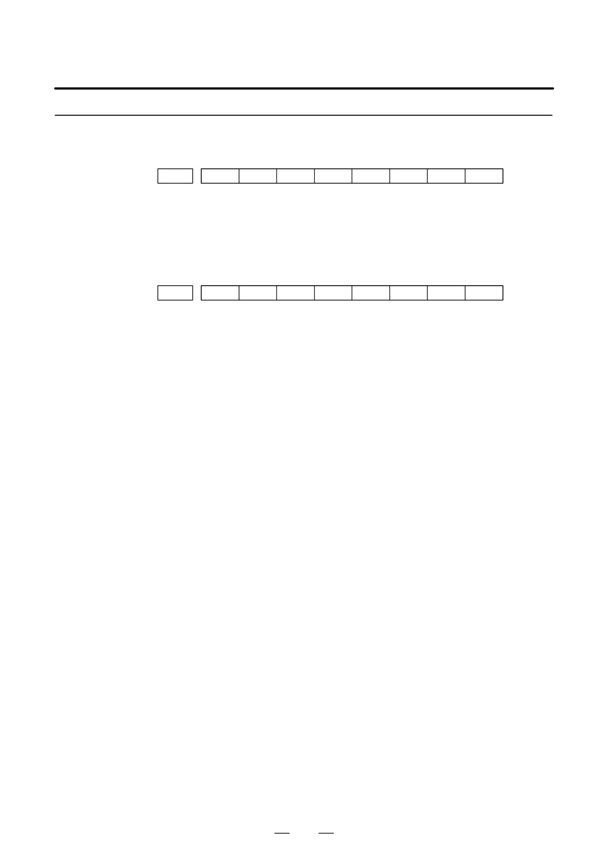
3103
NMH
[Data type] Bit
NMH The system alarm history screen is:
0 : Not displayed.
1 : Displayed.
#7
#6
#5
#4
#3
#2
#1
#0
3110
OPC
[Data type] Bit
OPC On the operation history screen, the [CLEAR] soft key is:
0 : Not enabled.
1 : Enabled.
37
1. DISPLAY AND OPERATION
B-64115EN/02
This function enables the saving of external operator messages as a
1.5
record.
EXTERNAL
The record can be viewed on the external operator message history screen.
OPERATOR
MESSAGES
RECORD
1.5.1
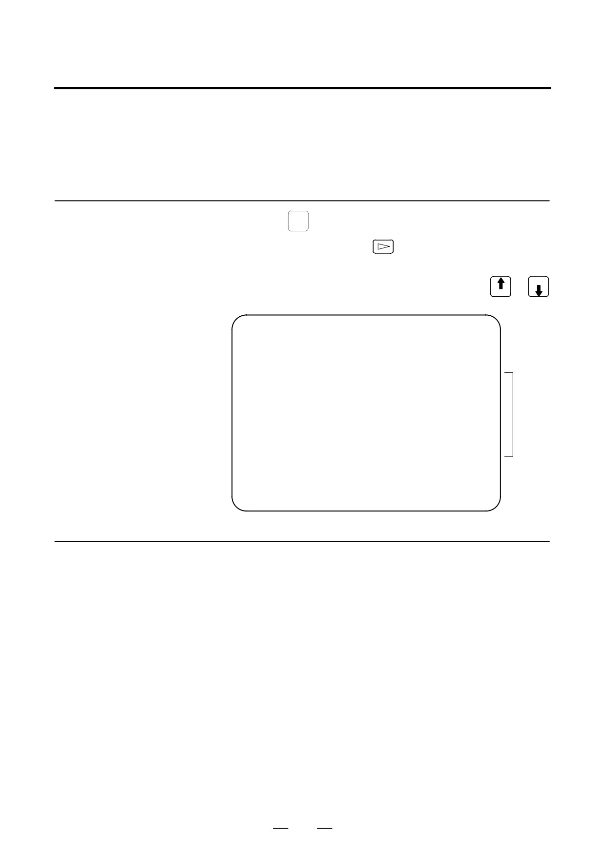
(1) Press the
MESSAGE
function key.
Screen Display
(2) Press the rightmost soft key
(3) Press the [MSGHIS] soft key.
(4) To display the previous or subsequent screen, press the
or PAGE
PAGE
key.
→ Date,
MESSAGE HISTORY
O1234 N12345
time, and
02/04/01 17:25:00
PAGE : 1
page
No. ****
→ Message
No.
Up to 255 characters
Display
range
MEM STRT MTN FIN ALM 17:25:00
[
][ MSGHIS ][
][
][
]
1.5.2
(1) The recorded external operator message can be deleted by setting the
MMC bit (bit 0 of parameter No. 3113) to 1.
Deletion of External
Pressing the [CLEAR] soft key erases all the records of the external
Operator Messages
operator message.
Record
(2) The MS1 and MS0 bits (bits 7 and 6 of parameter No. 3113) specify
the number of records to be displayed on the external operator message
history screen. When the bits are changed, all external operator
message records retained up to that point are erased.
38
B-64115EN/02
1. DISPLAY AND OPERATION
1.5.3
Parameter
#7
#6
#5
#4
#3
#2
#1
#0
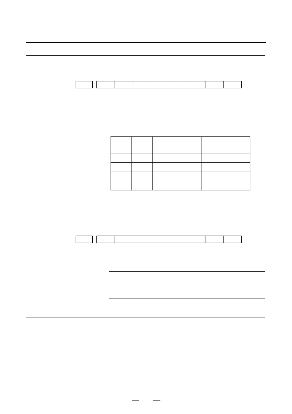
3113
MS1
MS0
MHC
#0 (MHC)
The records of an external operator message:
0 : Cannot be erased.
1 : Can be erased.
#6, #7 (MS0,MS1)
These bits set the number of characters to be retained in each record of an
external operator message, as well as the number of records, as shown in
the following table:
Number of charac-
MS1
MS0
Number of records
ters in each record
0
0
255
8
0
1
200
10
1
0
100
18
1
1
50
32
* An external operator message of up to 255 characters can be specified.
Combining the MS1 bit and MS0 bit (bits 7 and 6 of parameter No.
3113) selects the number of records by limiting the number of
characters to be retained as the record of an external operator message.
#7
#6
#5
#4
#3
#2
#1
#0
3112
OMH
#2 (OMH)
The external operator message history screen is:
0 : Not displayed.
1 : Displayed.
NOTE
After setting this parameter, briefly turn the power off, then
on again.
1.5.4
When the number of an external operator message is specified, the system
starts updating the records of the specified message. The system
Notes
continues to perform update until another external operator message is
specified or until an instruction to delete the records of the external
operator message is specified.
39