FANUC Series Series 16i-TB, Series 18i-TB, Series 160i-TB, Series 180i-TB. OPERATOR’S MANUAL - page 16
21. PATTERN DATA INPUT
B-63524EN/01
PROGRAMMING
FUNCTION
21.3
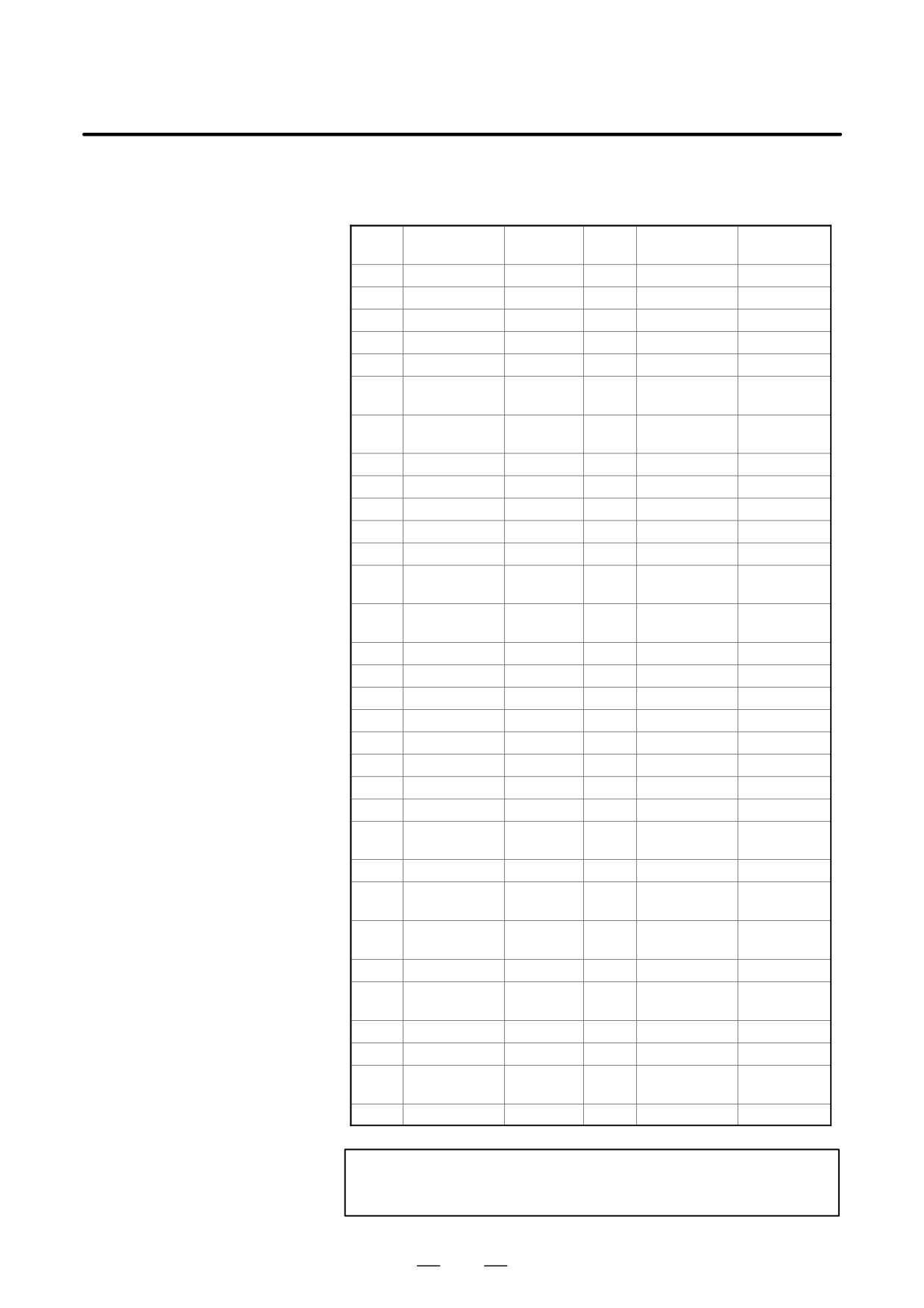
Table.21.3 (a) Characters and codes to be used for the pattern
CHARACTERS AND
data input function
CODES TO BE USED
Char-
Char-
Code
Comment
Code
Comment
acter
acter
FOR THE PATTERN
A
065
6
054
DATA INPUT
B
066
7
055
FUNCTION
C
067
8
056
D
068
9
057
E
069
032
Space
F
070
!
033
Exclama-
tion mark
G
071
”
034
Quotation
mark
H
072
#
035
Hash sign
I
073
$
036
Dollar sign
J
074
%
037
Percent
K
075
&
038
Ampersand
L
076
’
039
Apostrophe
M
077
(
040
Left
parenthesis
N
078
)
041
Right
parenthesis
O
079
042
Asterisk
P
080
+
043
Plus sign
Q
081
,
044
Comma
R
082
-
045
Minus sign
S
083
046
Period
T
084
/
047
Slash
U
085
:
058
Colon
V
086
;
059
Semicolon
W
087
<
060
Left angle
bracket
X
088
=
061
Equal sign
Y
089
>
062
Right angle
bracket
Z
090
?
063
Question
mark
0
048
@
064
HAt”mark
1
049
[
091
Left square
bracket
2
050
^
092
3
051
¥
093
Yen sign
4
052
]
094
Right squar
bracket
5
053
_
095
Underscore
NOTE
Right and left parentheses cannot be used.
429
21.
PATTERN DATA INPUT
FUNCTION
PROGRAMMING
B-63524EN/01
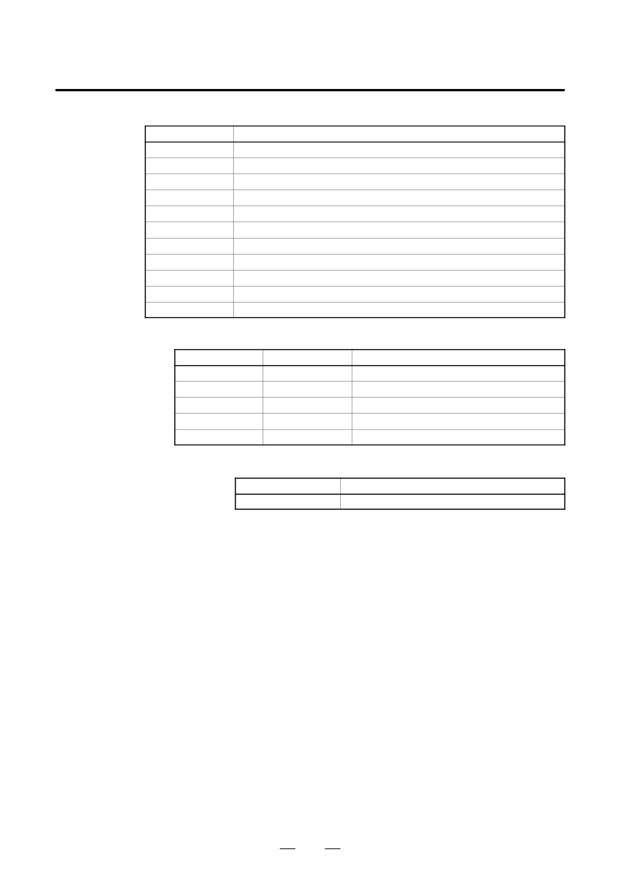
Table 21.3 (b) Numbers of subprograms employed in the pattern data input function
Subprogram No.
Function
O9500
Specifies character strings displayed on the pattern data menu.
O9501
Specifies a character string of the pattern data corresponding to pattern No.1
O9502
Specifies a character string of the pattern data corresponding to pattern No.2
O9503
Specifies a character string of the pattern data corresponding to pattern No.3
O9504
Specifies a character string of the pattern data corresponding to pattern No.4
O9505
Specifies a character string of the pattern data corresponding to pattern No.5
O9506
Specifies a character string of the pattern data corresponding to pattern No.6
O9507
Specifies a character string of the pattern data corresponding to pattern No.7
O9508
Specifies a character string of the pattern data corresponding to pattern No.8
O9509
Specifies a character string of the pattern data corresponding to pattern No.9
O9510
Specifies a character string of the pattern data corresponding to pattern No.10
Table. 21.3 (c) Macro instructions used in the pattern data input function
G code
H code
Function
G65
H90
Specifies the menu title.
G65
H91
Specifies the pattern name.
G65
H92
Specifies the pattern data title.
G65
G93
Specifies the variable name.
G65
H94
Specifies the comment.
Table. 21.3 (d) System variables employed in the pattern data input function
System variable
Function
#5900
Pattern No. selected by user.
430
III. OPERATION
B-63524EN/01
OPERATION
1. GENERAL
GENERAL
1
433
1. GENERAL
OPERATION
B-63524EN/01
1.1
MANUAL
OPERATION
Explanations
D Manual reference
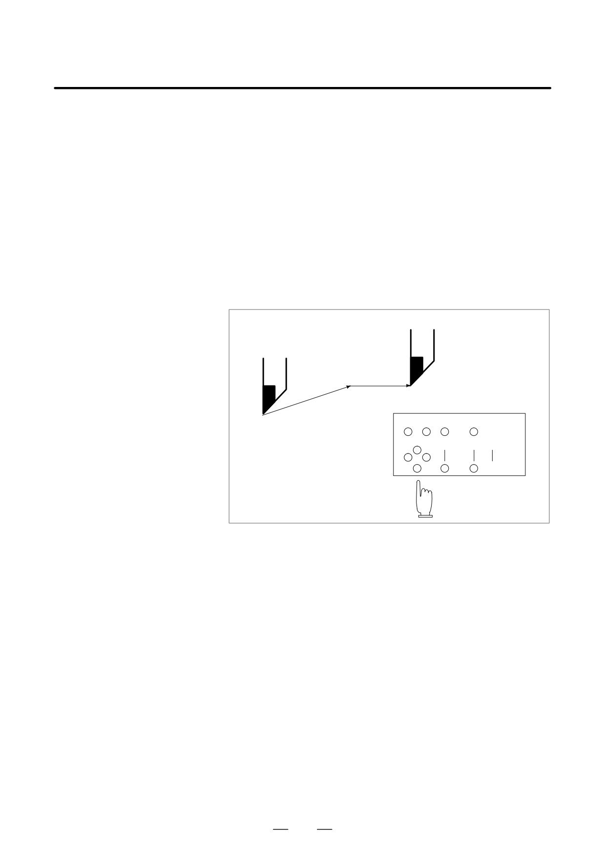
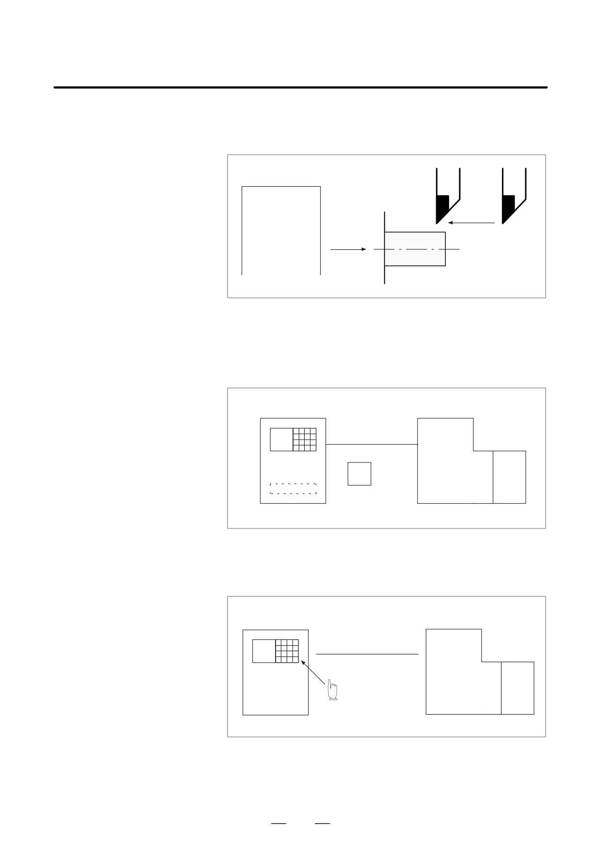
The CNC machine tool has a position used to determine the machine
position return (See
position.
Section III-3.1)
This position is called the reference position, where the tool is replaced
or the coordinate are set. Ordinarily, after the power is turned on, the tool
is moved to the reference position.
Manual reference position return is to move the tool to the reference
position using switches and pushbuttons located on the operator’s panel.
Reference position
Tool
Machine operator’s panel
Fig. 1.1 (a) Manual reference position return
The tool can be moved to the reference position also with program
commands.
This operation is called automatic reference position return (See Section
II-6).
434
B-63524EN/01
OPERATION
1. GENERAL
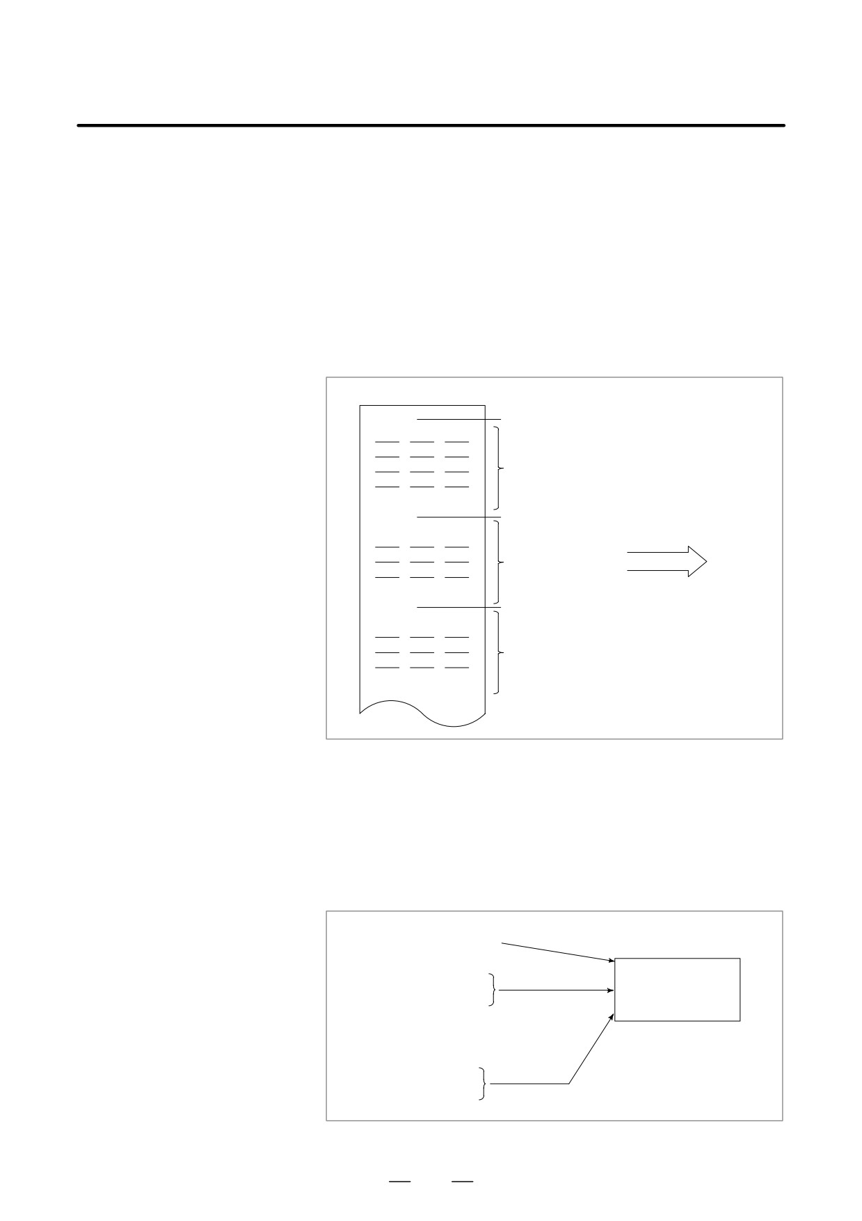
D The tool movement by
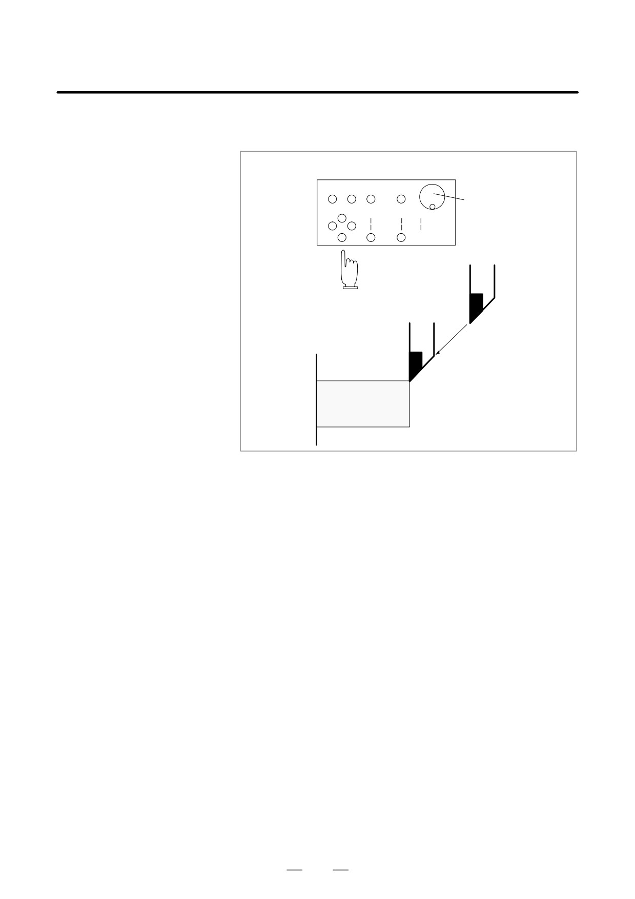
Using machine operator’s panel switches, push buttons, or the manual
manual operation
handle, the tool can be moved along each axis.
Machine operator’s panel
Manual
pulse
generator
Tool
Workpiece
Fig. 1.1 (b) The tool movement by manual operation
The tool can be moved in the following ways:
(i)
Jog feed (See Section III-3.2)
The tool moves continuously while a push button remains pressed.
(ii) Incremental feed (See Section III-3.3)
The tool moves by the predetermined distance each time a button is
pressed.
(iii) Manual handle feed (See Section III-3.4)
By rotating the manual handle,the tool moves by the distance
corresponding to the degree of handle rotation.
435
1. GENERAL
OPERATION
B-63524EN/01
Automatic operation is to operate the machine according to the created
1.2
program. It includes memory, MDI, and DNC operations. (See Section
TOOL MOVEMENT
III-4).
BY PROGRAMMING -
AUTOMATIC
Program
OPERATION
01000
;
M_S_T
;
Tool
G92_X_ ;
G00...
;
G01
;
Fig. 1.2 (a) Tool Movement by Programming
Explanations
D Memory operation
After the program is once registered in memory of CNC, the machine can
be run according to the program instructions. This operation is called
memory operation.
CNC
Memory
Fig. 1.2 (b) Memory Operation
D MDI operation
After the program is entered, as an command group, from the MDI
keyboard, the machine can be run according to the program. This
operation is called MDI operation.
CNC MDI keyboard
Machine
Manual program
input
Fig. 1.2 (c) MDI operation
D DNC operation
The machine can be operated by reading a program directly from an
external input/output device, without having to register the program in
CNC memory. This is called DNC operation.
436
B-63524EN/01
OPERATION
1. GENERAL
1.3
AUTOMATIC
OPERATION
Explanations
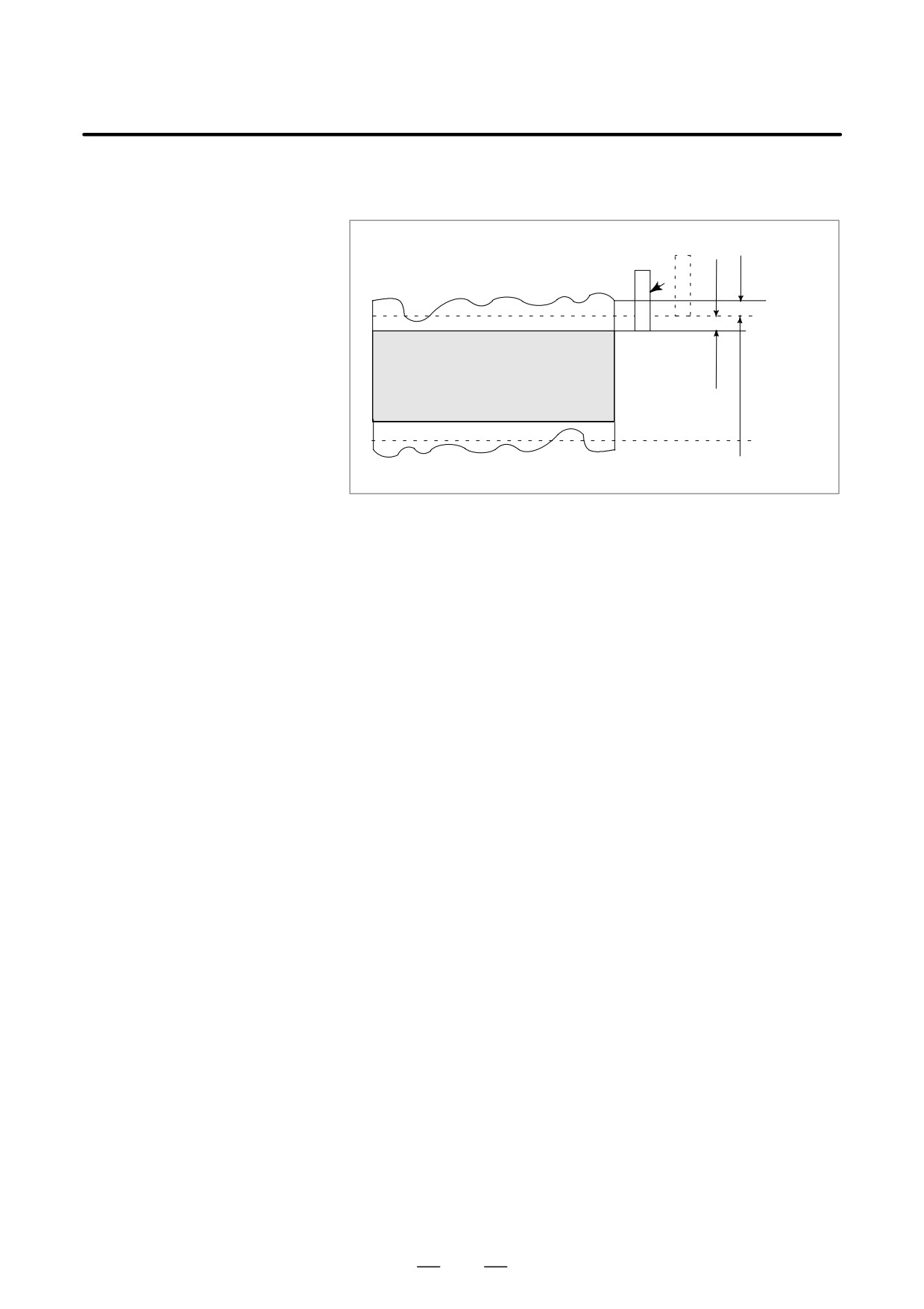
D Program selection
Select the program used for the workpiece. Ordinarily, one program is
prepared for one workpiece. If two or more programs are in memory,
select the program to be used, by searching the program number (Section
III-9.3).
In memory or on a tape
O1001
Program number
G92
- - - - - -
Work-1 program
M30
O1002
Program number
Program number
G92
- - - - - -
search
Work-2 program
Automatic
operation
M30
O1003
Program number
G92
- - - - - -
Work-3 program
M30
Fig. 1.3 (a) Program Selection for Automatic Operation
D Start and stop
Pressing the cycle start push button causes automatic operation to start.
(See Section III-4)
By pressing the feed hold or reset push button, automatic operation pauses
or stops. By specifying the program stop or program termination
command in the program, the running will stop during automatic
operation. When one process machining is completed, automatic
operation stops.
Start
Cycle start
Stop
Feed hold
Automatic operation
Reset
Program stop Stop caused
Program end
by program
Fig. 1.3 (b) Start and Stop for Automatic Operation
437
1. GENERAL
OPERATION
B-63524EN/01
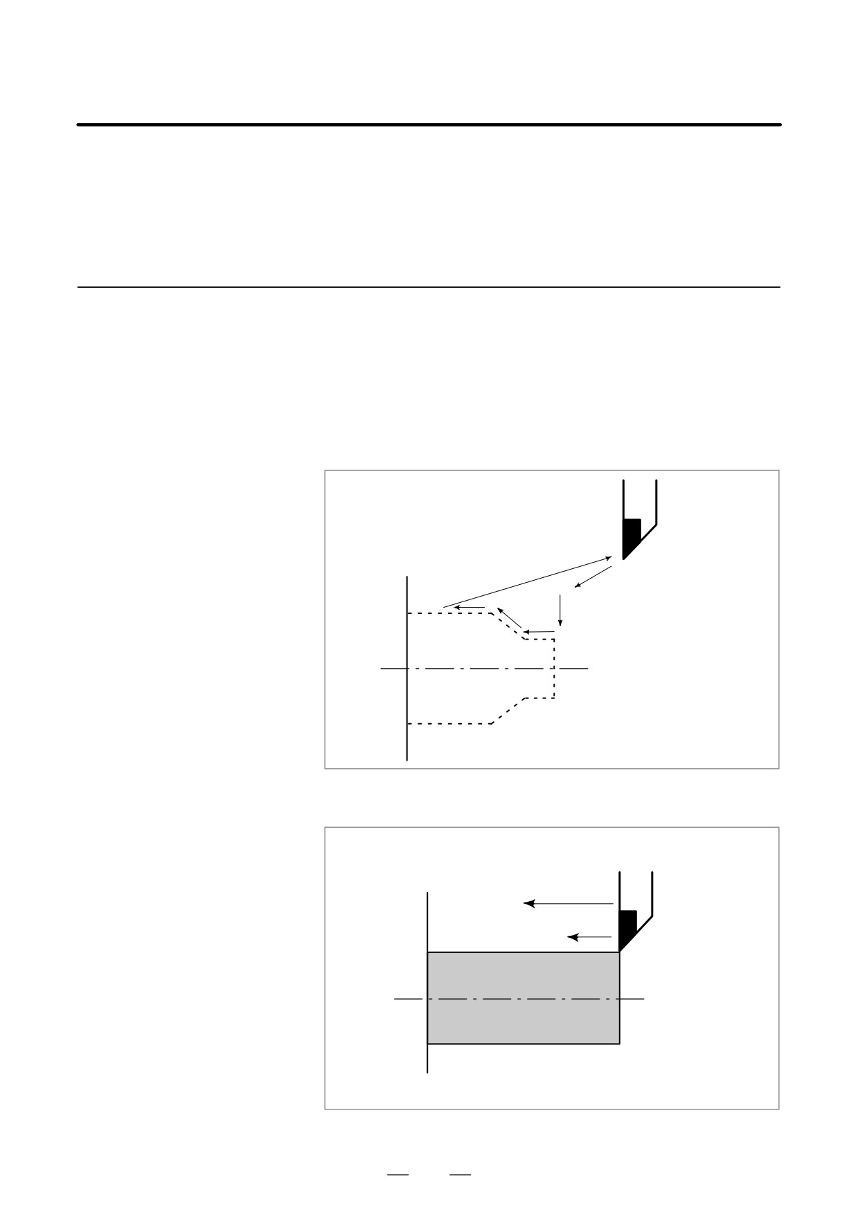
D Handle interruption (See
While automatic operation is being executed, tool movement can overlap
Section III-4.6)
automatic operation by rotating the manual handle.
Grinding
wheel (tool)
Workpiece
Depth of cut by
manual feed
Depth of cut specified
by a program
Fig. 1.3 (c) Handle Interruption for Automatic Operation
438
B-63524EN/01
OPERATION
1. GENERAL
Before machining is started, the automatic running check can be
1.4
executed. It checks whether the created program can operate the machine
TESTING A
as desired. This check can be accomplished by running the machine
PROGRAM
actually or viewing the position display change (without running the
machine) (See Section III-5).
1.4.1
Check by Running the
Machine
Explanations
D Dry run (See Section
Remove the workpiece, check only movement of the tool. Select the tool
III-5.4)
movement rate using the dial on the operator’s panel.
Tool
Fig. 1.4.1 (a) Dry run
D Feedrate override (See
Check the program by changing the rate specified in the program.
Section III-5.2)
Feed rate specified by program :
100 mm/min.
Feed rate after feed rate
Tool
override : 20 mm/min.
Workpiece
Fig. 1.4.1 (b) Feedrate Override
439
1. GENERAL
OPERATION
B-63524EN/01
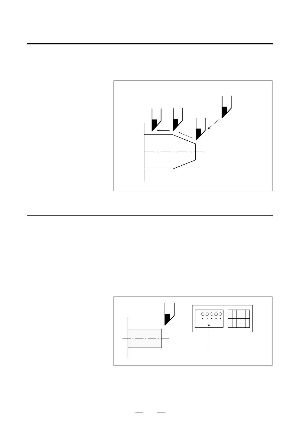
D Single block (See
When the cycle start push button is pressed, the tool executes one
Section III-5.5)
operation then stops. By pressing the cycle start again, the tool executes
the next operation then stops. The program is checked in this manner.
Cycle start
Cycle start
Cycle start
Cycle start
Tool
Workpiece
Fig. 1.4.1 (c) Single Block
1.4.2
How to View the
Position Display
Change without
Running the Machine
Explanations
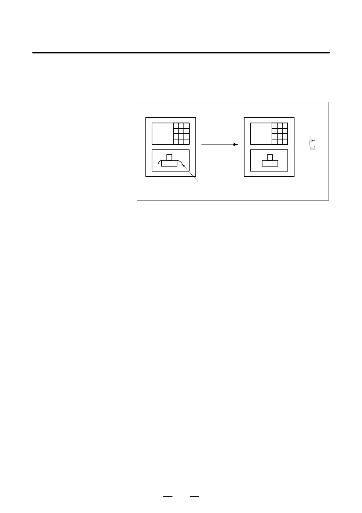
D Machine lock
CRT/MDI
X
Z
Tool
Workpiece
The tool remains stopped, and only the
positional displays of the axes change.
Fig. 1.4.2 Machine Lock
D Auxiliary function lock
When automatic running is placed into the auxiliary function lock mode
during the machine lock mode, all auxiliary functions (spindle rotation,
tool replacement, coolant on/off, etc.) are disabled. (See Section III-5.1)
440
B-63524EN/01
OPERATION
1. GENERAL
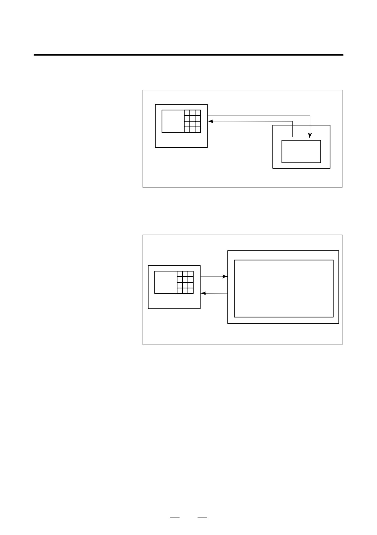
After a created program is once registered in memory, it can be corrected
1.5
or modified from the MDI panel (See Section III-9).
EDITING A PART
This operation can be executed using the part program storage/edit
PROGRAM
function.
Program registration
Program correction or modification
Tape reader
CNC
CNC tape (program)
Fig. 1.5 Part Program Editing
441
1. GENERAL
OPERATION
B-63524EN/01
The operator can display or change a value stored in CNC internal
1.6
memory by key operation on the MDI screen (See III-11).
DISPLAYING AND
SETTING DATA
Data setting
Data display
Screen Keys
MDI
CNC memory
Fig. 1.6 (a) Displaying and Setting Data
Explanations
D Offset value
Geometry
Wear com-
Setting
compensationpensation
Tool compensation
number1
12.3
25.0
Tool compensation
number2
20.0
40.0
Screen Keys
Display
Tool compensation
number3
⋅⋅⋅
⋅⋅⋅
⋅⋅⋅⋅⋅⋅⋅⋅⋅⋅⋅⋅⋅⋅⋅⋅
⋅⋅⋅
⋅⋅⋅
MDI
CNC memory
Fig. 1.6 (b) Displaying and Setting Offset Values
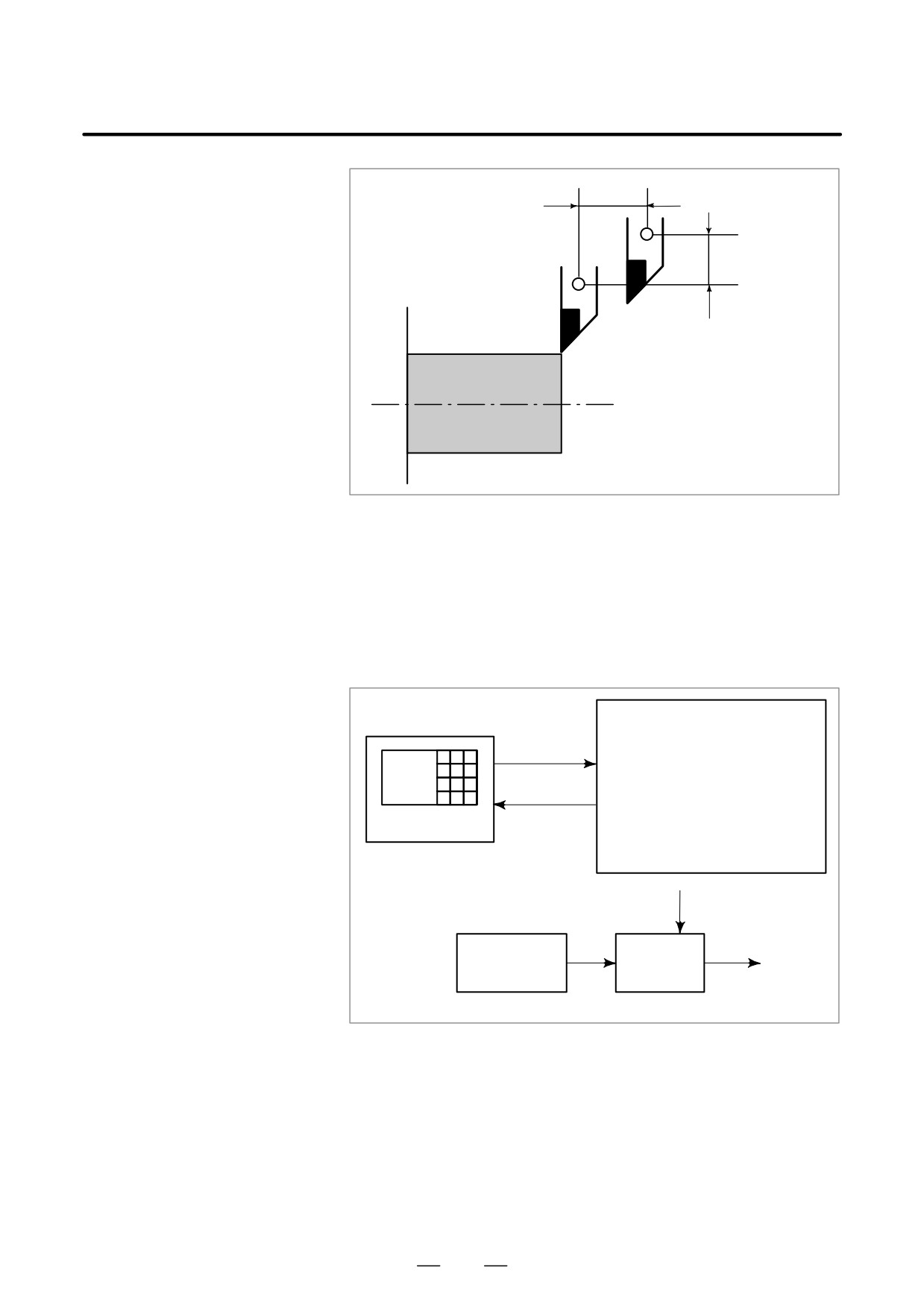
The tool has the tool dimension (length, diameter). When a workpiece is
machined, the tool movement value depends on the tool dimensions.
By setting tool dimension data in CNC memory beforehand,
automatically generates tool routes that permit any tool to cut the
workpiece specified by the program. Tool dimension data is called the
offset value
(See Section III-11.4.1).
442
B-63524EN/01
OPERATION
1. GENERAL
Offset value of the tool
Offset value of the tool
Tool
Workpiece
Fig. 1.6 (c) Offset Value
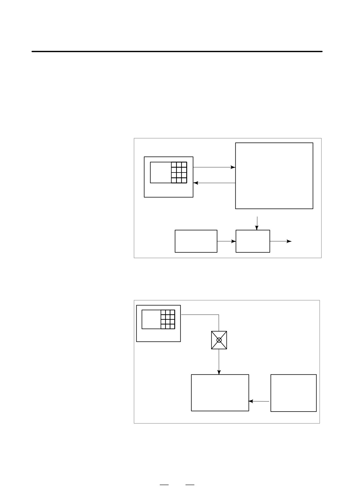
D Displaying and setting
Apart from parameters, there is data that is set by the operator in
operator’s setting data
operation. This data causes machine characteristics to change.
For example, the following data can be set:
⋅Inch/Metric switching
⋅I/O devices selection
⋅Mirror image cutting on/off
The above data is called setting data (See Section III-11.4.7).
Setting data
Setting
⋅Inch/Metric switching
⋅I/O device selection
⋅Mirror image ON/OFF setting
⋅
Screen Keys
Displaying
⋅
⋅
CNC Memory
Operational
characteristics
Program
Automatic
operation
Movement of
the machine
Fig. 1.6 (d) Displaying and Setting Operator’s setting data
443
1. GENERAL
OPERATION
B-63524EN/01
D Displaying and setting
The CNC functions have versatility in order to take action in
parameters
characteristics of various machines.
For example, CNC can specify the following:
⋅Rapid traverse rate of each axis
⋅Whether increment system is based on metric system or inch system.
⋅How to set command multiply/detect multiply (CMR/DMR)
Data to make the above specification is called parameters (See Section
III-11.5.1).
Parameters differ depending on machine tool.
Parameter
Rapid traverse rate
Setting
Position control
Reference position return
Backlash compensation data
Pitch error compensation
Screen Keys
Display
data
⋅
⋅
MDI
⋅
Movement
Program
Automatic
of the
operation
machine
Fig. 1.6 (e) Displaying and setting parameters
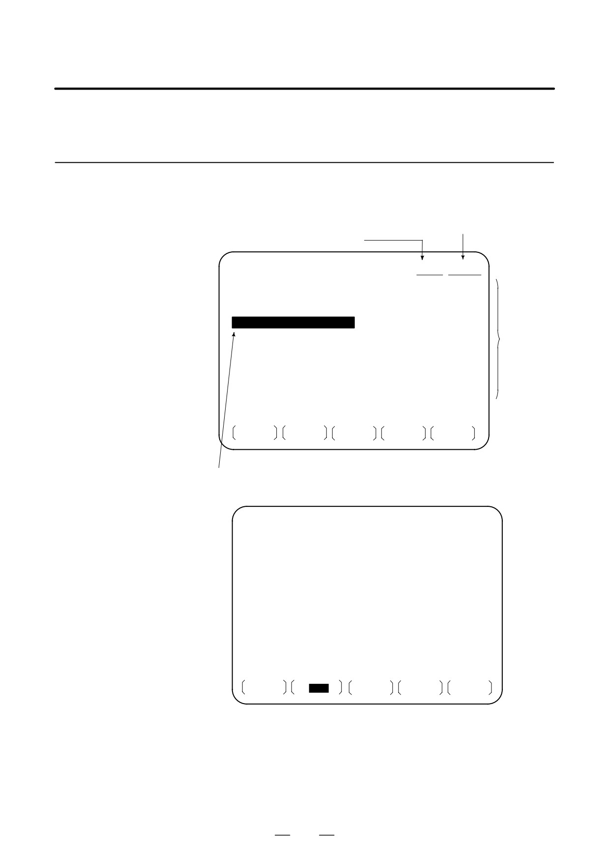
D Data protection key
A key called the data protection key can be defined. It is used to prevent
part programs, offset values, parameters, and setting data from being
registered, modified, or deleted erroneously
(See Section III-11).
Data Setting
Screen Keys
Protection Key
MDI
Registration /
alteration inhibition
Machine operator’s
panel
Program
Offset value
Signal
Parameters
Setting data
CNC memory
Fig. 1.6 (f) Data Protection Key
444
B-63524EN/01
OPERATION
1. GENERAL
1.7
DISPLAY
1.7.1
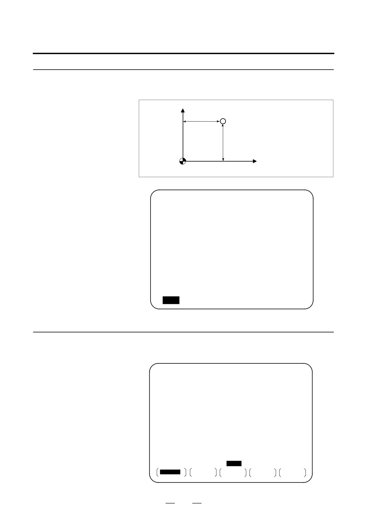
The contents of the currently active program are displayed. In addition,
the programs scheduled next and the program list are displayed.
Program Display
(See Section III-11.2.1)
Active sequence number
Active program number
PROGRAM
O1100 N00005
N1 G90 G17 G00 G41 X250.0 Z550.0 ;
N2 G01 Z900.0 F150 ;
N3 X450.0 ;
N4 G03 X500.0 Z1150.0 R650.0 ;
N5 G02 X900.0 R-250.0 ;
Program
N6 G03 X950.0 Z900.0 R650.0 ;
content
N7 G01 X1150.0 ;
N8 Z550.0 ;
N9 X700.0 Z650.0 ;
N10 X250.0 Z550.0 ;
N11 G00 G40 X0 Z0 ;
>_
MEM STOP * * *
* * *
13 : 18 : 14
PRGRM
CHECK
CURRNT
NEXT
(OPRT)
Currently executed program
The cursor indicates the currently executed location
PROGRAM
O1100 N00003
SYSTEM EDITION B1A1 - 03
PROGRAM NO. USED ’
10
FREE ’
53
MEMORY AREA USED ’ 960
FREE ’ 5280
PROGRAM LIBRARY LIST
O0001 O0002 O0010 O0020 O0040 O0050
O0100 O0200 O1000 O1100
>_
EDIT
* * * *
* * *
* * *
13 : 18 : 14
PRGRM
LIB
JOPRTK
445
1. GENERAL
OPERATION
B-63524EN/01
1.7.2
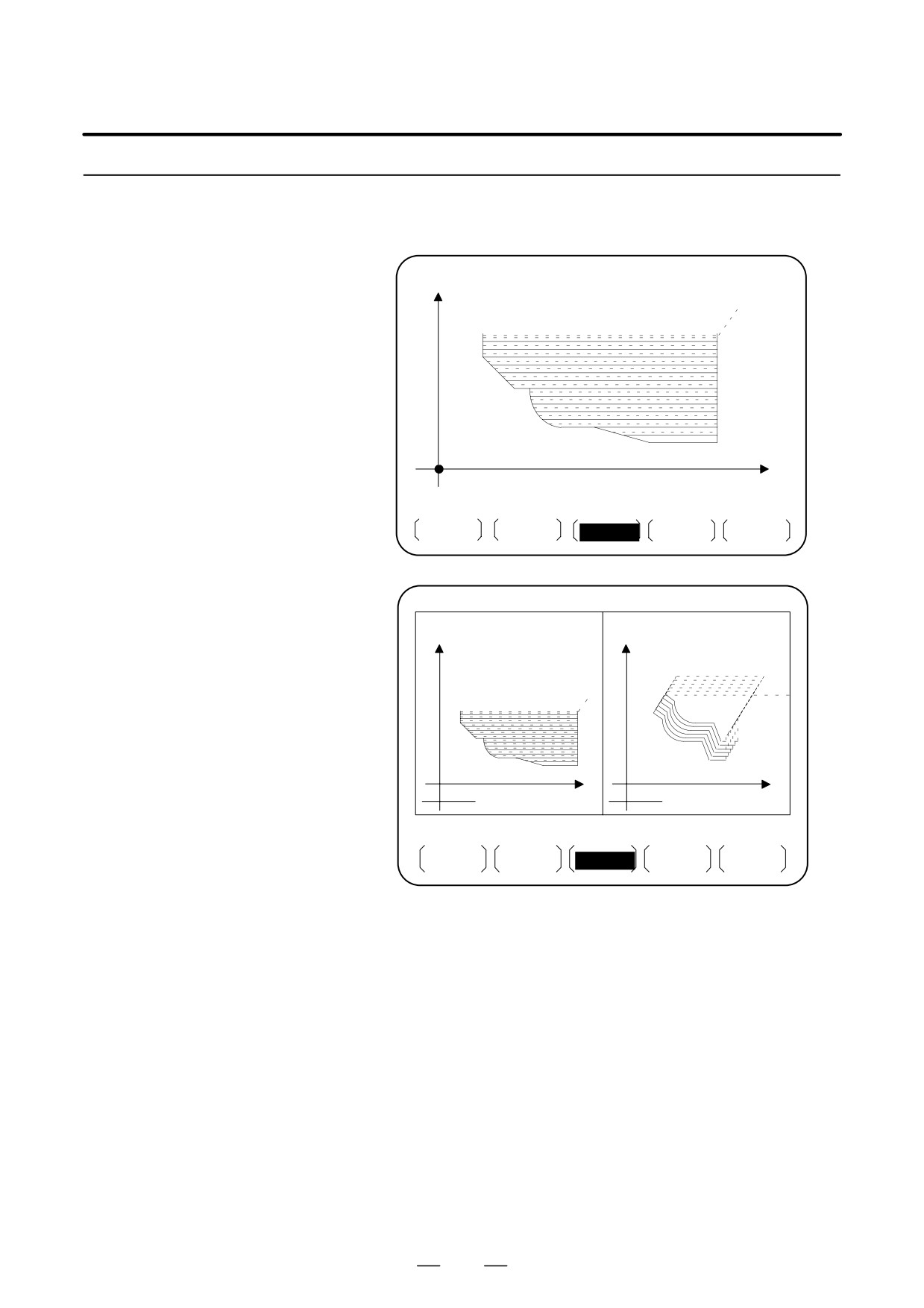
The current position of the tool is displayed with the coordinate values.
The distance from the current position to the target position can also be
Current Position
displayed.
(See Section III-11.1 to 11.1.3)
Display
X
z
x
Z
Workpiece coordinate system
ACTUAL POSITION(ABSOLUTE) O1000 N00010
X
123.456
Z
456.789
C
90.000
PART COUNT
5
RUN TIME
0H15M CYCLE TIME 0H 0M38S
MEM STRT MTN ***
09:06:35
[
ABS
] [ REL
] [ ALL
] [ HNDL ] [
] [(OPRT)]
1.7.3
When a trouble occurs during operation, error code and alarm message are
displayed on CRT screen. See APPENDIX G for the list of error codes
Alarm Display
and their meanings.
(See Section III-7.1)
ALARM MESSAGE
O1000 N00003
010
IMPROPER G-CODE
>_
MEM STOP * * * *
* * *
ALM
19 : 55 : 22
ALARM
MSG
HISTRY
446

B-63524EN/01
OPERATION
1. GENERAL
1.7.4
When this option is selected, two types of run time and number of parts
are displayed on the screen. (See Section lll-11.4.9)
Parts Count Display,
Run Time Display
ACTUAL POSITION(ABSOLUTE) O1000 N00010
X
123.456
Z
456.789
C
90.000
PART COUNT
5
RUN TIME
0H15M CYCLE TIME 0H 0M38S
MEM STRT MTN ***
09:06:35
[
ABS
] [ REL
] [ ALL
] [ HNDL ] [
] [(OPRT)]
447
1. GENERAL
OPERATION
B-63524EN/01
1.7.5
The graphic can be used to draw a tool path for automatic operation and
manual operation, thereby indicating the progress of cutting and the
Graphic Display (See
position of the tool.
(See Section III-12)
Section III-12)
X
O0001 N00021
X 200.000
Z 200.000
Z
MEM STRT* * * *
FIN
08 : 00 : 53
G.PRM
GRAPH
ZOOM
(OPRT)
1-path control
HEAD1 O0001
N00021
HEAD2 O0020
N00020
X
X1
200.000
X
X2
220.000
1
Z1
200.000
2
Z2
160.000
Z1
Z2
62.5
62.5
MEM STRT
* * *
FIN
08 : 24 : 56
HEAD1
G.PRM
GRAPH
ZOOM
(OPRT)
2-path control
448
B-63524EN/01
OPERATION
1. GENERAL
Programs, offset values, parameters, etc. input in CNC memory can be
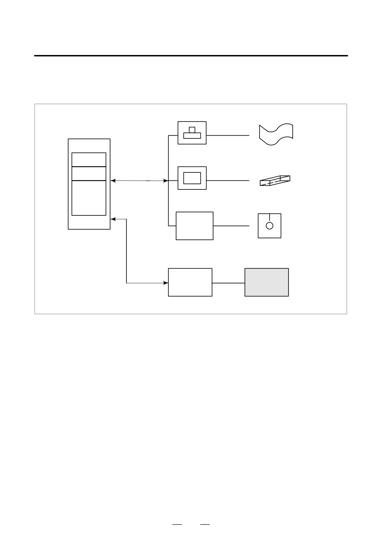
1.8
output to paper tape, cassette, or a floppy disk for saving. After once
DATA OUTPUT
output to a medium, the data can be input into CNC memory. (See III-8.)
Portable tape reader
FANUC PPR
Memory
Paper tape
Program
FANUC Floppy Cassette
Reader/puncher
FANUC Floppy
Offset
interface
cassette adaptor
Parameters
Floppy disk
SYSTEM P
CNC
Automatic programming system
Memory card
Memory card
adapter
(incorporated CNC)
Fig. 1.8 Data Output
449
2. OPERATIONAL DEVICES
OPERATION
B-63524EN/01
OPERATIONAL DEVICES
2
The available operational devices include the setting and display unit
attached to the CNC, the machine operator’s panel, and external
input/output devices such as a Handy File and etc.
450
B-63524EN/01
OPERATION
2. OPERATIONAL DEVICES
The setting and display units are shown in Subsections 2.1.1 to 2.1.5 of
2.1
Part III.
SETTING AND
DISPLAY UNITS
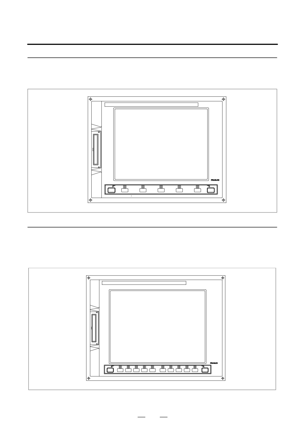
7.2″/8.4″ LCD-mounted type CNC control unit: III-2.1.1
9.5″/10.4″ LCD-mounted type CNC control unit: III-2.1.2
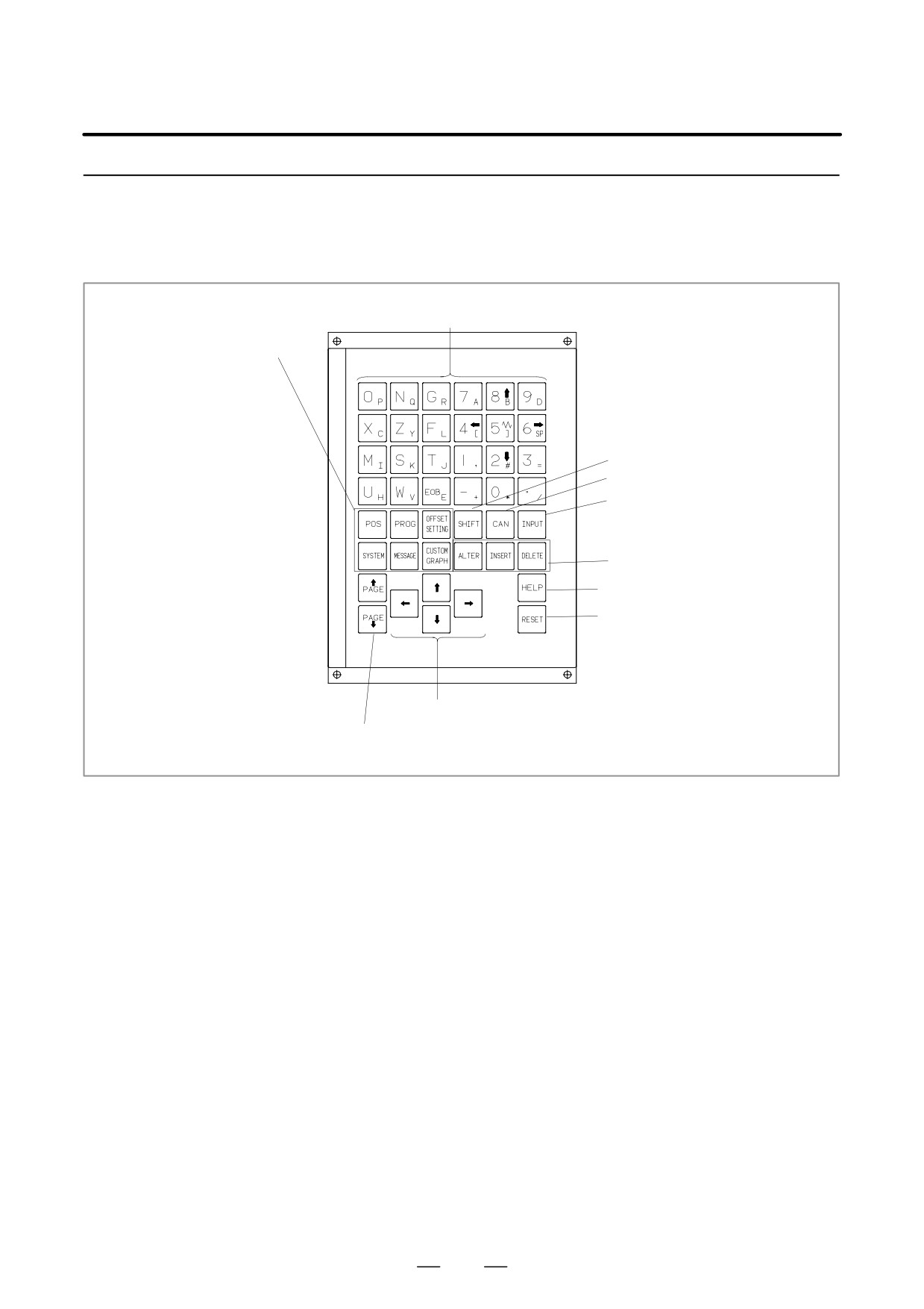
Stand-Alone type small MDI unit: III-2.1.3
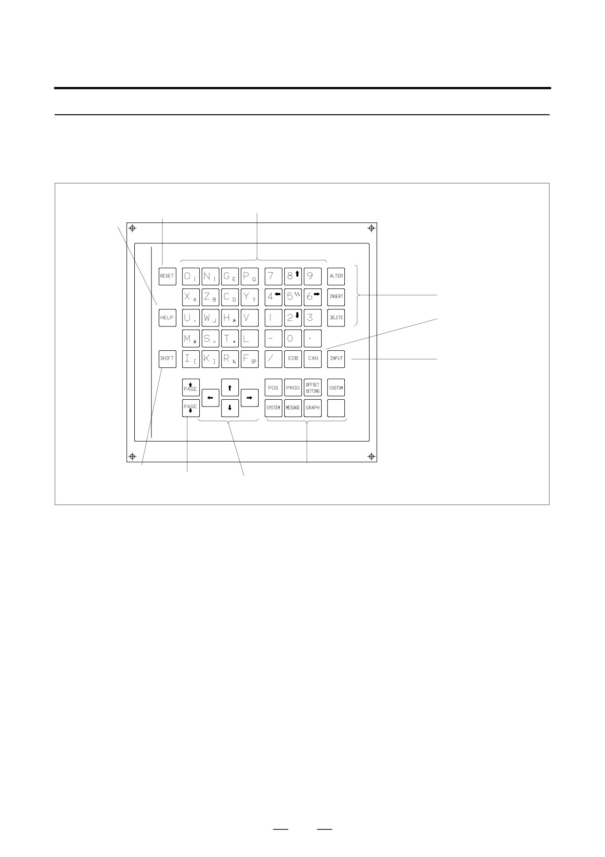
Stand-Alone type standard MDI unit: III-2.1.4
Stand-Alone type 61 full key MDI unit: III-2.1.5
451
2. OPERATIONAL DEVICES
OPERATION
B-63524EN/01
2.1.1
7.2″/8.4″ LCD-mounted
Type CNC Control Unit
2.1.2
9.5″/10.4″
LCD-mounted Type
CNC Control Unit
452
B-63524EN/01
OPERATION
2. OPERATIONAL DEVICES
2.1.3
Stand-alone Type
Small MDI Unit
Address/numeric keys
Function keys
Shift key
Cancel (CAN) key
Input key
Edit keys
Help key
Reset key
Cursor keys
Page change keys
453
2. OPERATIONAL DEVICES
OPERATION
B-63524EN/01
2.1.4
Stand-alone Type
Standard MDI Unit
Address/numeric keys
Reset key
Help key
Edit keys
Cancel (CAN) key
Input key
Shift key
Function keys
Page change
Cursor keys
keys
454
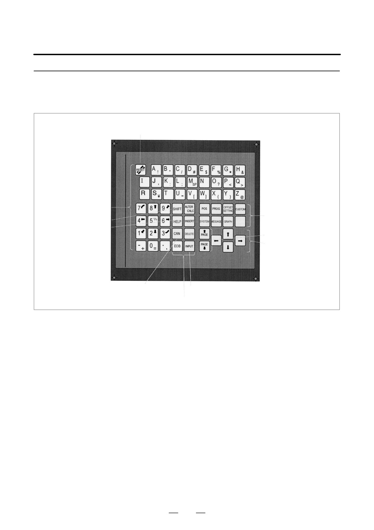
B-63524EN/01
OPERATION
2. OPERATIONAL DEVICES
2.1.5
Stand-alone Type 61 Full
Key MDI Unit
Reset key
Address/numeric keys
Function keys
Shift key
Help key
Page change keys
Cursor keys
Cancel (CAN) key
Input key
Edit keys
455
2. OPERATIONAL DEVICES
OPERATION
B-63524EN/01
2.2
EXPLANATION OF
THE KEYBOARD
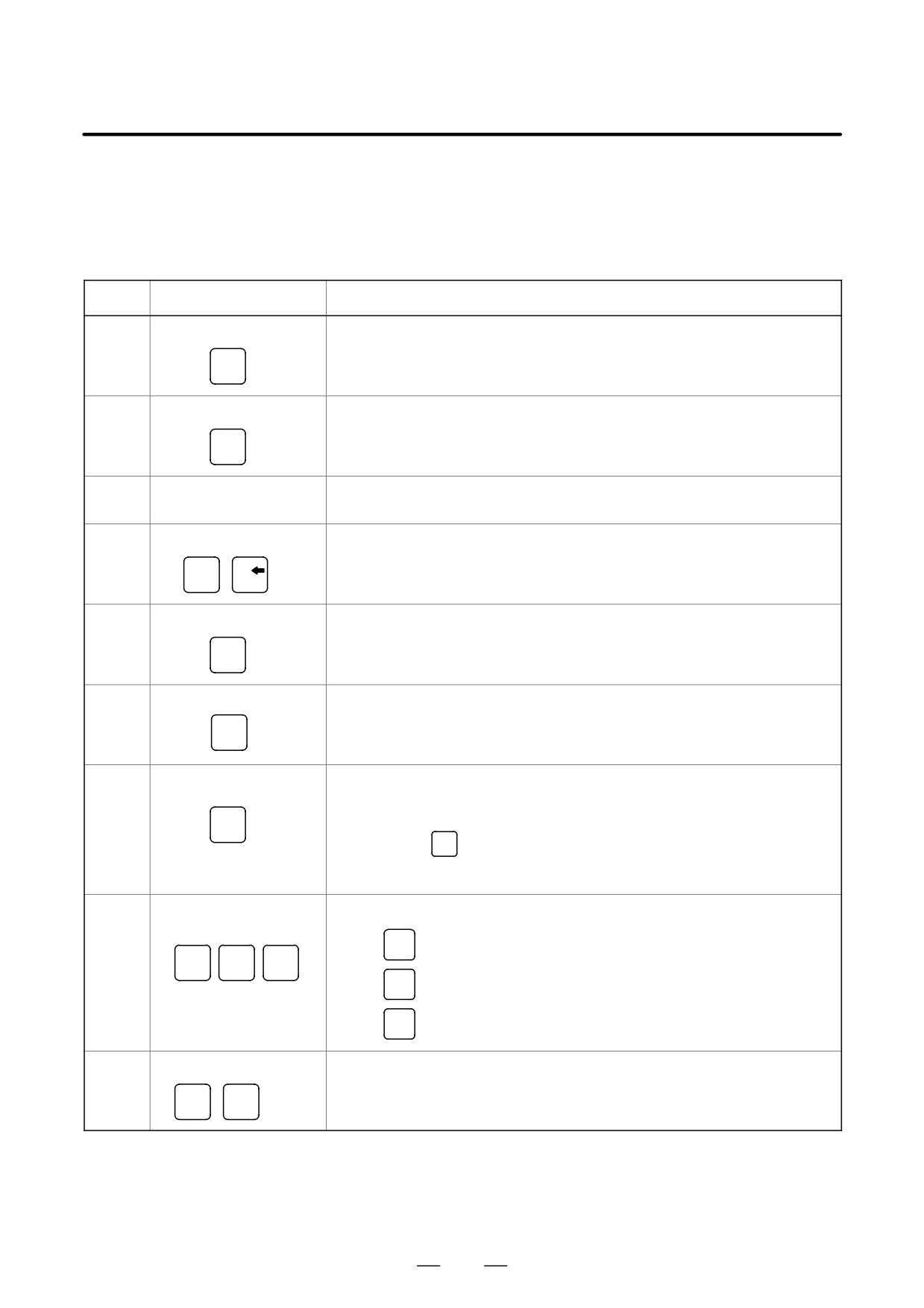
Table 2.2 Explanation of the MDI keyboard
Number
Name
Explanation
1
RESET key
Press this key to reset the CNC, to cancel an alarm, etc.
RESET
2
HELP key
Press this key to display how to operate the machine tool, such as MDI key op-
eration, or the details of an alarm which occurred in the CNC (Help function).
HELP
In case of 160i/180i/160is/180is, this key is assigned to “ESC” key of the person-
al computer.
3
Soft keys
The soft keys have various functions, according to the Applications. The soft key
functions are displayed at the bottom of the CRT screen.
4
Address and numeric keys
Press these keys to input alphabetic, numeric, and other characters.
N
4
…
)
5
SHIFT key
Some keys have two characters on their keytop. Pressing the <SHIFT> key
switches the characters. Special character Ê is displayed on the screen when a
SHIFT
character indicated at the bottom right corner on the keytop can be entered.
6
INPUT key
When an address or a numerical key is pressed, the data is input to the buffer,
and it is displayed on the CRT screen. To copy the data in the key input buffer to
INPUT
the offset register, etc., press the <INPUT> key. This key is equivalent to the [IN-
PUT] key of the soft keys, and either can be pressed to produce the same result.
7
Cancel key
Press this key to delete the last character or symbol input to the key input buffer.
When the key input buffer displays
CAN
>N001X100Z_
and the cancel
CAN
key is pressed, Z is canceled and
>N001X100_
is displayed.
8
Program edit keys
Press these keys when editing the program.
ALTER
(In case of 160i/180i/160is/180is, this key is
: Alteration
ALTER
INSERT
DELETE
assigned to “Tab” key of the personal computer.)
INSERT
: Insertion
DELETE
: Deletion
9
Function keys
Press theses keys to switch display screens for each function.
See sec. 2.3 for details of the function keys.
…
POS
PROG
456
B-63524EN/01
OPERATION
2. OPERATIONAL DEVICES
Table 2.2 Explanation of the MDI keyboard
Number
Name
Explanation
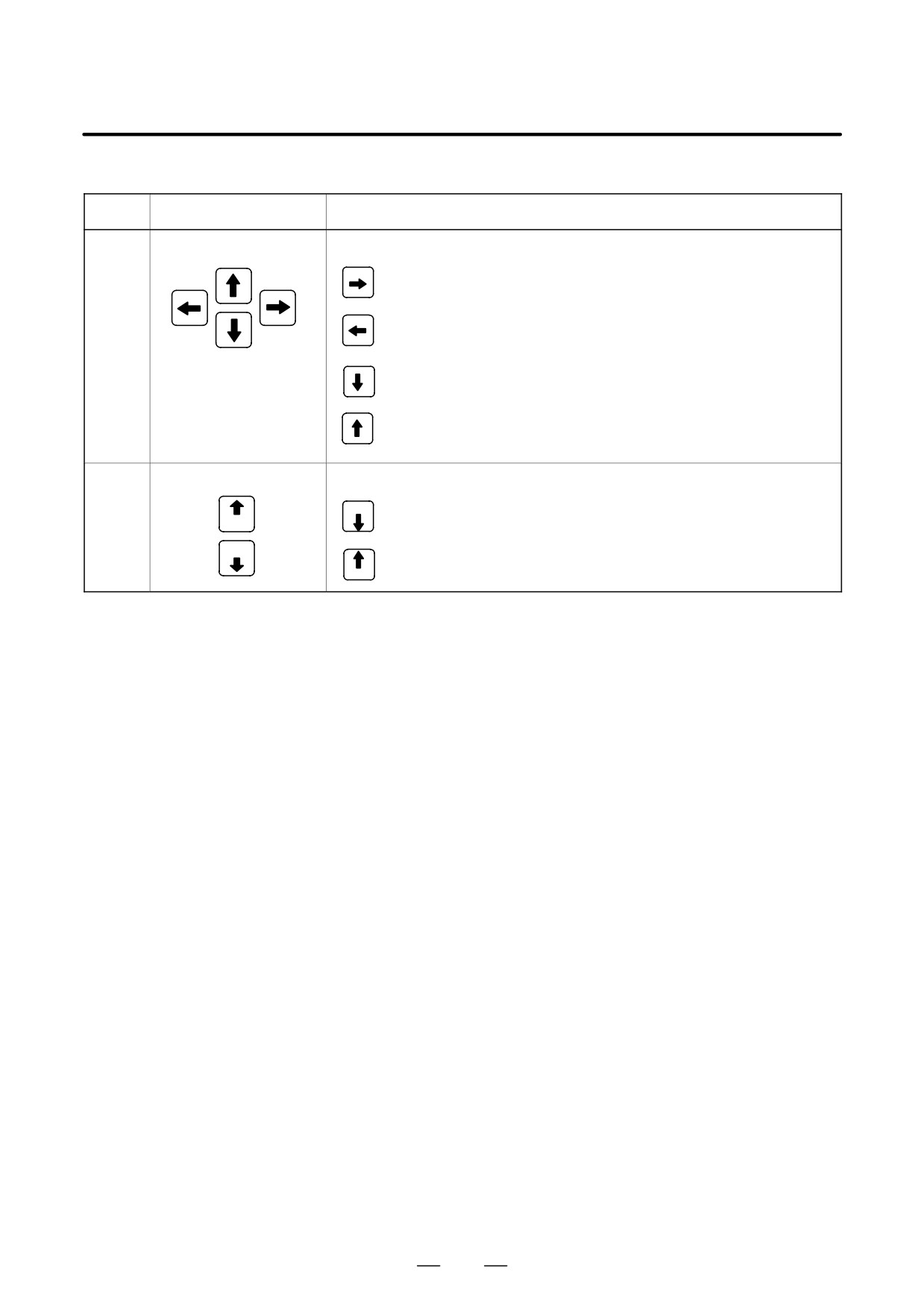
10
Cursor move keys
There are four different cursor move keys.
: This key is used to move the cursor to the right or in the forward
direction. The cursor is moved in short units in the forward direction.
: This key is used to move the cursor to the left or in the reverse
direction. The cursor is moved in short units in the reverse direction.
: This key is used to move the cursor in a downward or forward
direction. The cursor is moved in large units in the forward direction.
: This key is used to move the cursor in an upward or reverse direction.
The cursor is moved in large units in the reverse direction.
11
Page change keys
Two kinds of page change keys are described below.
PAGE
: This key is used to changeover the page on the screen in the forward
PAGE
direction.
PAGE
: This key is used to changeover the page on the screen in the reverse
PAGE
direction.
457
2. OPERATIONAL DEVICES
OPERATION
B-63524EN/01
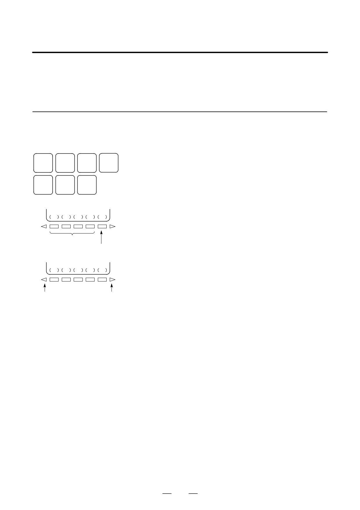
The function keys are used to select the type of screen (function) to be
2.3
displayed. When a soft key
(section select soft key) is pressed
FUNCTION KEYS
immediately after a function key, the screen (section) corresponding to the
AND SOFT KEYS
selected function can be selected.
2.3.1
General Screen
Operations
1
Press a function key on the MDI panel. The chapter selection soft
OFFSET
POS
PROG
CUSTOM
keys that belong to the selected function appear.
SETTING
2
Press one of the chapter selection soft keys. The screen for the
SYSTEM
MESSAGE
GRAPH
selected chapter appears. If the soft key for a target chapter is not
displayed, press the continuous menu key (next-menu key).
Function keys
In some cases, additional chapters can be selected within a chapter.
3
When the target chapter screen is displayed, press the operation
(OPRT)
selection key to display data to be manipulated.
4
To redisplay the chapter selection soft keys, press the return menu
Chapter selection
key.
soft keys
Operation
selection
key
The general screen display procedure is explained above. However,
the actual display procedure varies from one screen to another. For
details, see the description of individual operations.
Return menu
Continuous menu
key
key
458