FANUC Series Series 16i-TB, Series 18i-TB, Series 160i-TB, Series 180i-TB. OPERATOR’S MANUAL - page 15
20. TWO-PATH CONTROL
B-63524EN/01
PROGRAMMING
FUNCTION
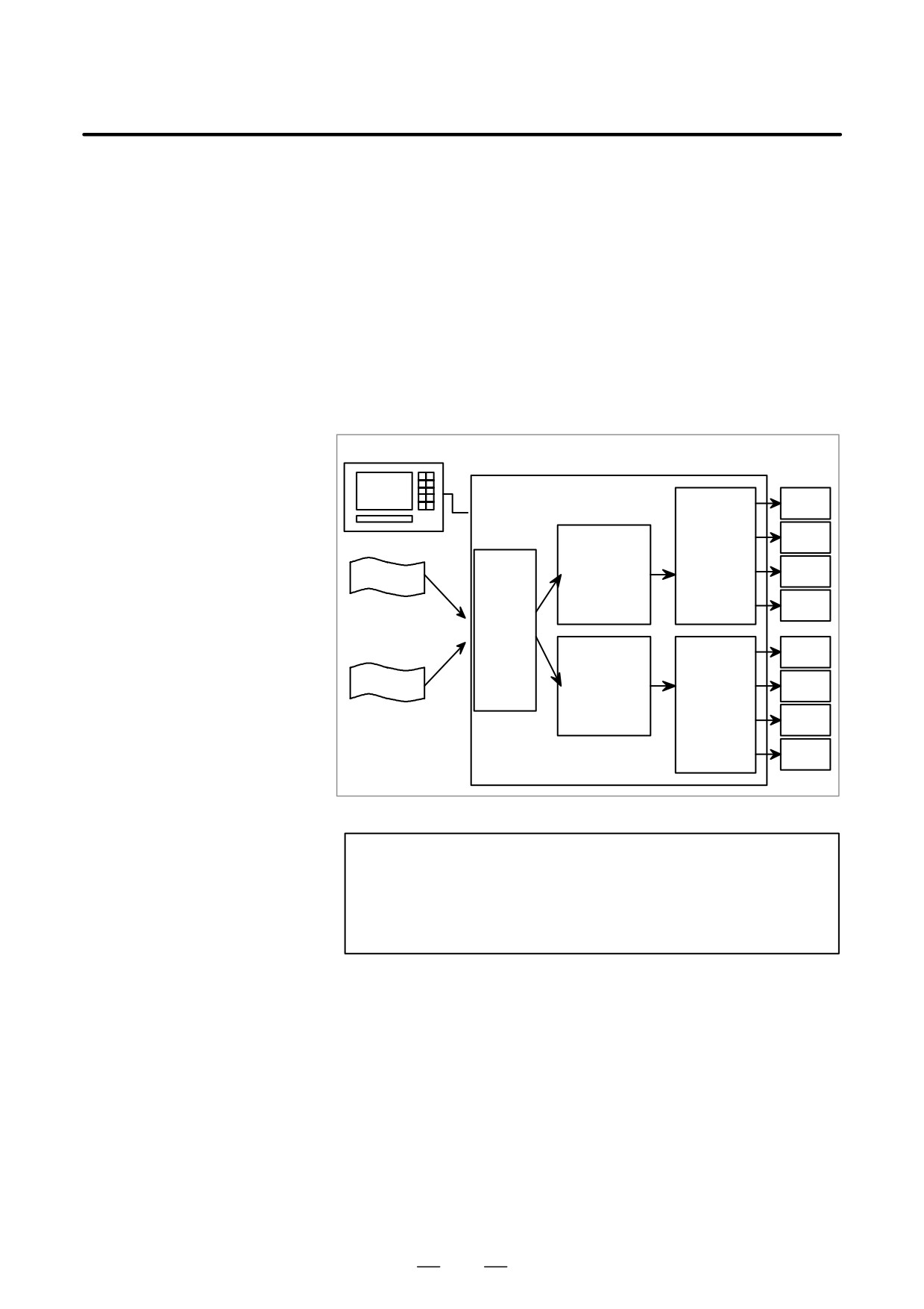
D Controlling two tool
The operations of two tool posts are programmed independently of each
posts independently at
other, and each program is stored in program memory for each tool post.
the same time
When automatic operation is to be performed, each tool post is activated
after selecting a program for machining with tool post 1 and a program
for machining with tool post 2 from the programs stored in program
memory for each tool post. Then the programs selected for the tool posts
are executed independently at the same time. When tool post 1 and tool
post 2 need to wait for each other during machining, the waiting function
is available (Section 20.2)
Just one MDI is provided for the two tool posts. Before operation and
display on the MDI, the tool post selection signal is used to switch
between the two tool posts.
MDI
16/18/160/180-TB
X1 axis
Tool post 1
control
Z1 axis
(such as
Program
interpolation
memory for
and axis
tool post 1
control)
Reader/
Program for tool
punch
post 1
interface
X2 axis
Tool post 2
Program
control
memory for
Z2
axis
(such as
tool post 2
interpolation
Program for tool
and axis
post 2
control)
Fig. 20.1 (c) Controlling two tool posts independently at the same time
NOTE
Simultaneous operation of the two tool posts or the
operation of only a single tool post can be selected by
pressing a key on the machine operator’s panel. For details,
refer to the manual supplied by the machine tool builder.
399
20. TWO-PATH CONTROL
FUNCTION
PROGRAMMING
B-63524EN/01
20.2
WAITING FOR TOOL
POSTS
Explanations
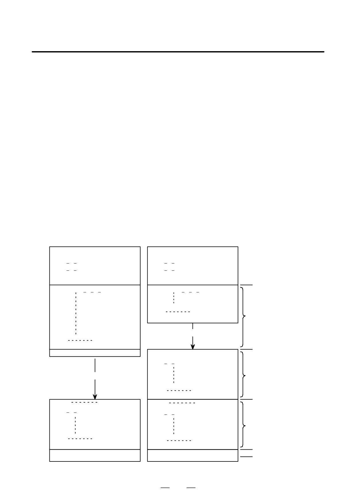
Control based on M codes is used to cause one tool post to wait for the
other during machining. By specifying an M code in a machining
program for each tool post, the two tool posts can wait for each other at
a specified block. When an M code for waiting is specified in a block for
one tool post during automatic operation, the other tool post waits for the
same M code to be specified before staring the execution of the next block.
This function is called the tool post waiting function.
A range of M codes used as M codes for waiting is to be set in the
parameters (Nos. 8110 and 8111) before hand.
Example
M100 to M103 are used as M codes for waiting.
Parameter setting: No. 8110= 100 (Minimum M code for waiting:
M100)
No. 8111= 103 (Maximum M code for waiting:
M103)
Tool post 1 program
Tool post 2 program
01357 ;
02468 ;
G50 X Z ;
G50 X Z ;
G00 X Z T0101 ;
G00 X Z T0202 ;
S1000 M03 ;
S2000 M03 ;
M100 ;
M100 ;
Waiting
N1100 G01 X Z F ;
N2100 G01 X Z F ;
Simultaneous,
independent operation
N2199
;
of tool post 1 (N1100 to
M101 ;
N1199) and tool post 2
(N2100 to N2199)
<Waiting (M101)>
N1199
;
M101 ;
Waiting
M102 ;
N2200 S3000 ;
G00 X Z T0202 ;
Operation of tool post
<Waiting (M102)>
2 (N2200 to N2299)
only
N2299
;
M102 ;
Waiting
N1300
;
N2300
;
Simultaneous,
G00 X Z T0505 ;
G00 X Z T0707 ;
independent operation
of tool post 1 (N1300 to
N1399) and tool post 2
(N2300 to N2399)
N1399
;
N2399
;
M103 ;
M103 ;
Waiting
M30 ;
M30 ;
End of program
400
20. TWO-PATH CONTROL
B-63524EN/01
PROGRAMMING
FUNCTION
NOTE
1
An M code for waiting must always be specified in a single
block.
2
If one tool post is waiting because of an M code for waiting
specified, and a different M code for waiting is specified with
the other tool post, an P/S alarm (No. 160) is raised, In this
case, both tool posts stop operation.
3
PMC-CNC interface
Unlike other M codes, the M code for waiting is not output
to the PMC.
4
Operation of a single tool post
If the operation of a single tool post is required, the M code
for waiting need not be deleted. By using the NOWT signal
to specify that waiting be ignored (G0063, #1), the M code
for waiting in a machining program can be ignored. For
details, refer to the manual supplied by the machine tool
builder.
401
20. TWO-PATH CONTROL
FUNCTION
PROGRAMMING
B-63524EN/01
20.3
TOOL POST
INTERFACE CHECK
20.3.1
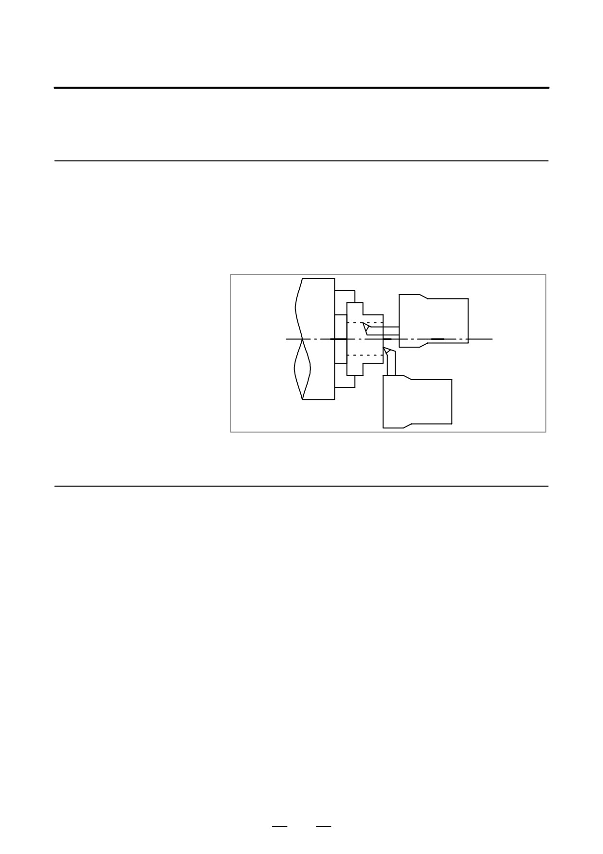
When two tool posts machine the same workpiece simultaneously, the
tool posts can approach each other very closely. If the two tool posts
General
interfere with each other due to a program error or any other setting error,
a serious damage such as a tool or machine destruction can occur.
The function “tool post interference check” is available which can
decelerate and stop the two tool posts before the tool posts interfere with
each other due to an incorrect command.
Tool post 2
Tool post 1
The contours of the two tool posts are checked to determine whether or
not an interference occurs.
To make a tool post interference check, data including the relationships
20.3.2
between the two tool posts and interference forbidden areas (that is, tool
Data Setting for the
shapes) needs to be set. The method of such data setting is described
Tool Post Interference
below.
Check Function
With the tool post interference check function, whether or not the two tool
posts interfere with each other is determined by checking if the
interference forbidden areas (based on the interference forbidden areas of
the currently selected tools) of the tool posts overlap each other after the
movement of the tool posts.
Explanations
D Position setting for
When reference point return operation is completed with all axes (X1, Z1,
reference points of two
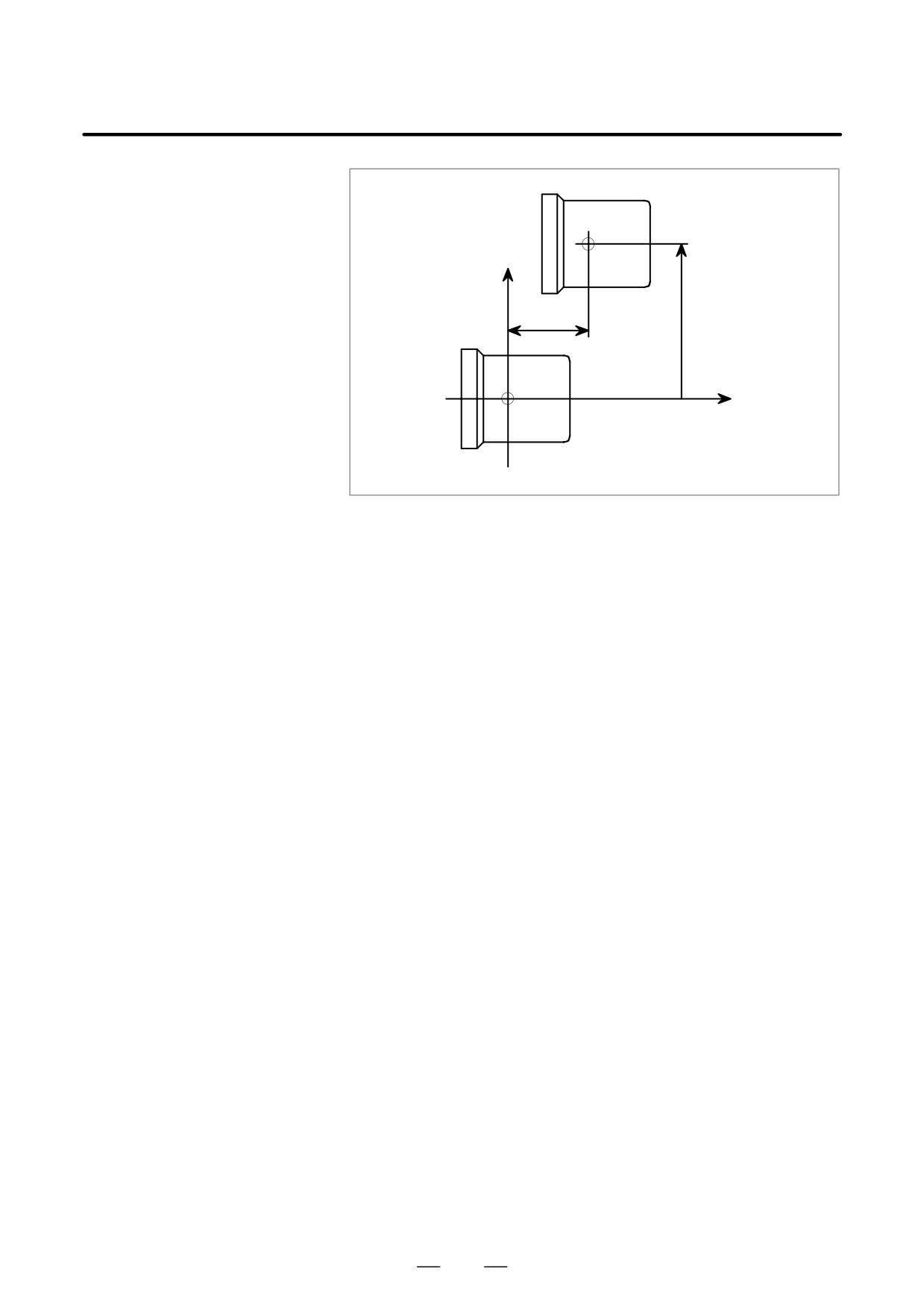
X2, Z2), the reference point of tool post 1 is set at the origin of the ZX
tool posts
plane coordinate system. At this time, the position of the reference point
of tool post 2 is set in a parameter. The next item describes the reference
points.
402
20. TWO-PATH CONTROL
B-63524EN/01
PROGRAMMING
FUNCTION
Tool post 2
+X
ζ
ε
+Z
Tool post 1
In the ZX plane coordinate system at the origin of which the reference
point of tool post 1 is set, set the X coordinate (ε) of the reference point
of tool post 2 in parameter No. 8151, and its Z coordinate (ζ) in parameter
No.8152.
The unit of setting is the least command increment. For an axis subject
to diameter specification, a diameter value is to be specified.
Measure (ε) and (ζ) when reference point return operation is completed
with the four axes (X1, Z1, X2, Z2). When the relative coordinate
parameters (Nos. 8151 and 8152) of the two tool posts are to be updated,
reference point return operation must always be completed with the four
axes beforehand. Otherwise, the internally memorized relational
positions of the tool posts are not updated to new parameter values.
403
20. TWO-PATH CONTROL
FUNCTION
PROGRAMMING
B-63524EN/01
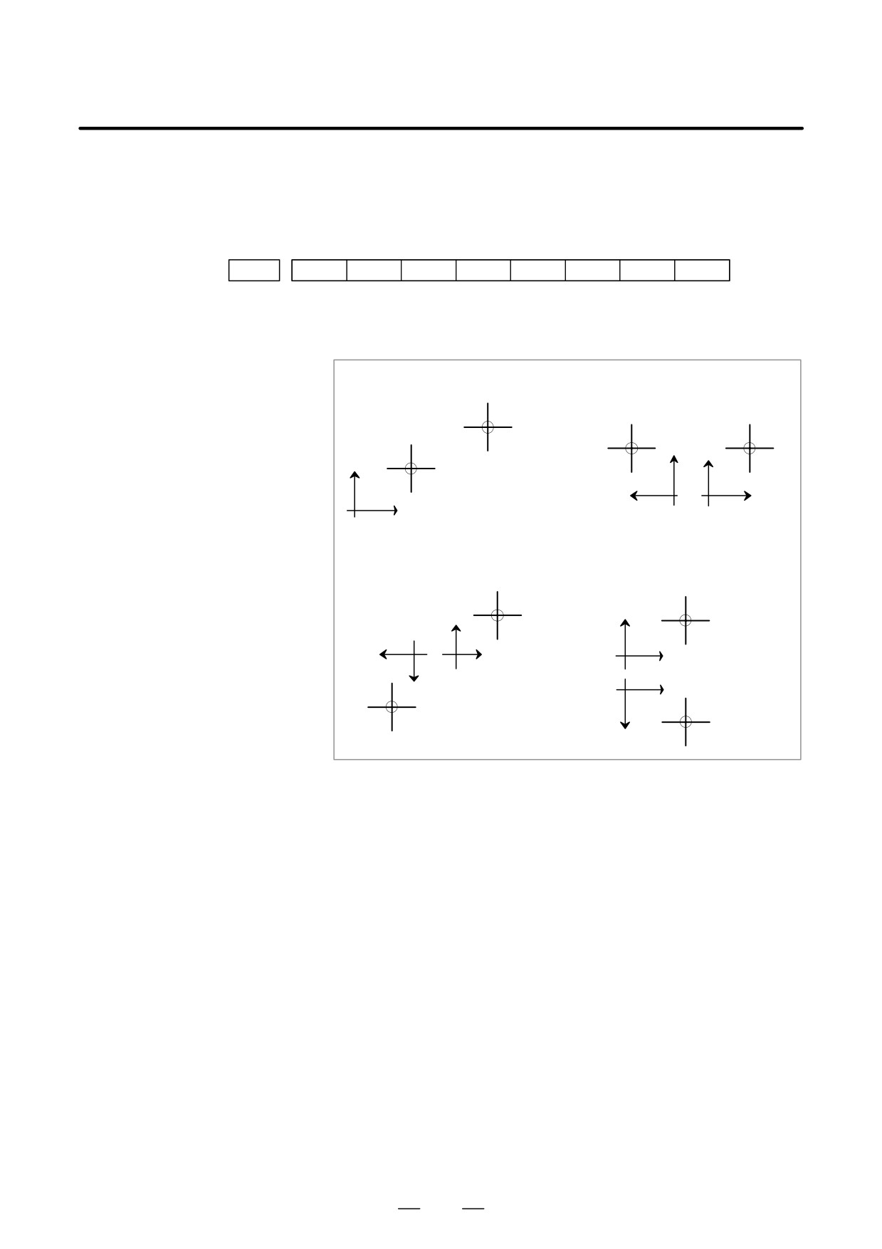
D Set the relationship
between the coordinate
systems of the two tool
posts in parameter
No.8140
#7
#6
#5
#4
#3
#2
#1
#0
8140
TY1
TY0
TY0, TY1:Set the relationship between the coordinate systems of the two
tool posts, with tool post 1 used as the reference.
(1) When TY1=0 and TY0=0
(2) When TY1=0 and TY0=1
Tool post 2
Tool post 2
Tool post 1
X X
X
Tool post 1
Z
Z
Z
(4) When TY1=1 and TY0=1
(3) When TY1=1and TY0=0
Tool post 1
X
Tool post 1
X
Z
Z
Z
Z
X
Tool post 2
X
Tool post 2
404
20. TWO-PATH CONTROL
B-63524EN/01
PROGRAMMING
FUNCTION
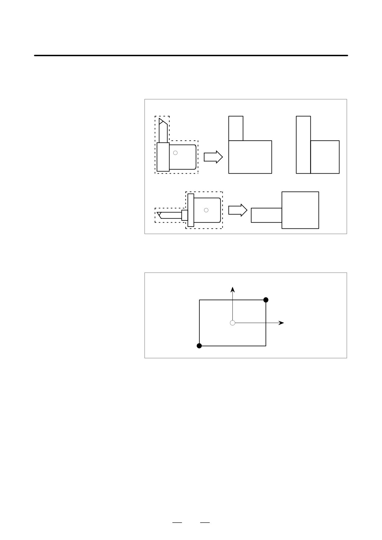
D Setting of interference
An interference forbidden area is set using a combination of two
forbidden area
rectangular areas. Some examples are shown below. The dashed lines
indicate interference forbidden areas.
(Example 1)
Area 1
Area 1
Area 2
or
Area 2
(Example 2)
Area 2
Area 1
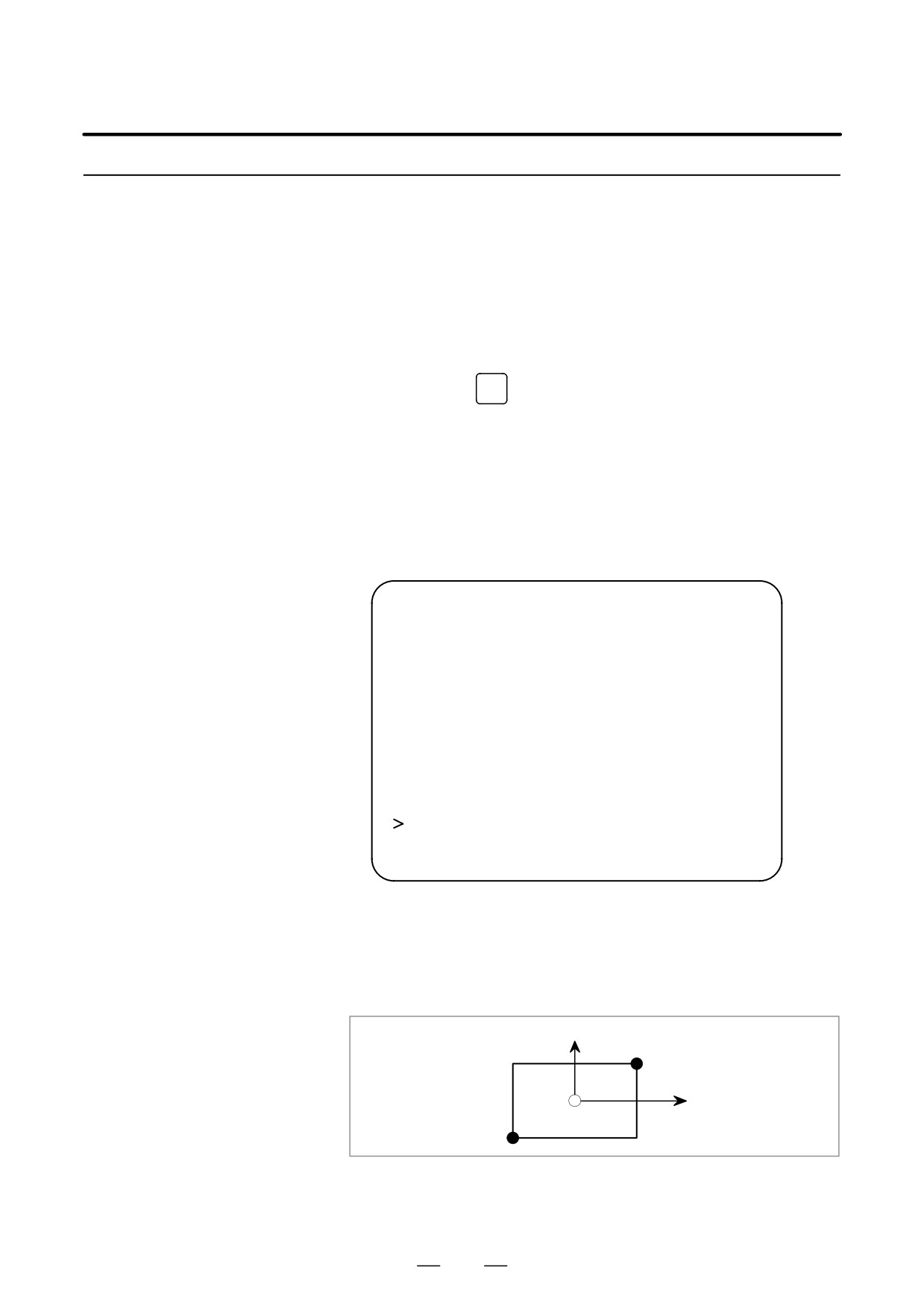
The coordinates of the upper and lower ends (points A and B shown
below) of each of two rectangles are set, with the reference position of the
tool post set as the origin.
X
A (X, Z)
Z
X > I
Reference position
Z > K
B (I, K)
See Section
20.3.3 for information about the coordinate setting
procedure.
405
20. TWO-PATH CONTROL
FUNCTION
PROGRAMMING
B-63524EN/01
20.3.3
Setting and Display of
Interference Forbidden
Areas for Tool Post
Interference Checking
Explanations
Display and set tool shape data (interference forbidden areas) according
to the procedure below.
OFFSET
(1) Press function
SETTING
key.
(2) Press the chapter selection soft key [TOOLFM].
(3) With the tool post selection signal, select a tool post for which
interference forbidden areas for tool post interference checking are to
be displayed and set.
(4) Display the screen including a tool number for which data is to be set.
Method 1:Select the screen by using the page keys and cursor keys.
Method 2:Enter a desired tool number, then press the soft key
[NO.SRH]
TOOL FORM DATA
O0001 N00001
OFFSET NO. = 01
AREA1
AREA 2
X =
20.000
X =
40.000
Z =
70.000
Z =
70.000
I =
-10.000
I =
20.000
K =
-50.000
K =
30.000
OFFSET NO
= 02
AREA1
AREA 2
X =
80.000
X =
-100.000
Z =
170.000
Z =
-60.000
I =
-100.000
I =
-140.000
K =
-120.000
K =
-120.000
_
S
0 T0000
MEM
* * * *
* * *
* * *
12 : 02 : 08 HEAD1
[ NO.SRH
][
][
][ +INPUT ][ INPUT ]
(5) Move the cursor to a data item to be set, with the cursor move keys.
(When data for point A is to be set, move the cursor to X and Z.
When data for point B is to be set, move the cursor to I and K.)
(6) With the numeric keys, enter the coordinates of point A or B.
(Fraction digits can be entered.)
X
A (X, Z)
Z
X > I
Z > K
B (I, K)
(7) By pressing the soft key [INPUT], the entered coordinates are set.
(Press the soft key [+INPUT] when an entered numeric value is to set
after it is added to data already set.)
406

20. TWO-PATH CONTROL
B-63524EN/01
PROGRAMMING
FUNCTION
NOTE
1
Tool number
The tool geometry data must be set for each tool number.
The tool number here refers to the offset number. When
both tool geometry offset and tool wear offset are used, the
tool number corresponds to the wear offset number. To use
two or more offset numbers for the same tool, the same data
for the tool must be set two or more times in the tool
geometry data.
2
Tool offset pairs
As for displaying and setting tool shape data (interference
forbidden areas), the maximum tool number is 64.
20.3.4
A tool post interference check is made when all conditions listed below
are satisfied.
Conditions for Making
(1) Parameter IFE (No. 8140#4) for enabling the tool post interference
a Tool Post
check function is set to 0.
Interference Check
(2) After power is turned on, reference point return operation is completed
with all axes (X1, Z1, X2, Z2). (When an absolute-position detector
is used, the matching between a machine position and
absolute-position detector position must be completed.)
(3) Offset numbers other than 0 are specified using T codes for two tool
posts.
(4) When manual mode is used, parameter IFM (No. 8140#3) for enabling
the tool post interference check function in manual mode is set to 1.
When all conditions for making a tool post interference check are
satisfied, the tool-post-interference-check-in-progress signal is
output to the PMC.
WARNING
The tool post interference check function can be executed
only when the number of the tool actually selected agrees
with the programmed tool number.
The function cannot be executed correctly if the tool is
selected by a manual operation or if no tool selection
command is specified after power-on.
407
20. TWO-PATH CONTROL
FUNCTION
PROGRAMMING
B-63524EN/01
20.3.5
when all conditions described in Section 20.3.4 are satisfied, a tool post
interference check is started. When a tool post interference check is made,
Execution of Tool Post
an interference forbidden area is set for the two tool posts by using the tool
Interference Checking
shape data corresponding to the currently selected tool numbers.
Then whether the areas interfere with each other is checked.
Explanations
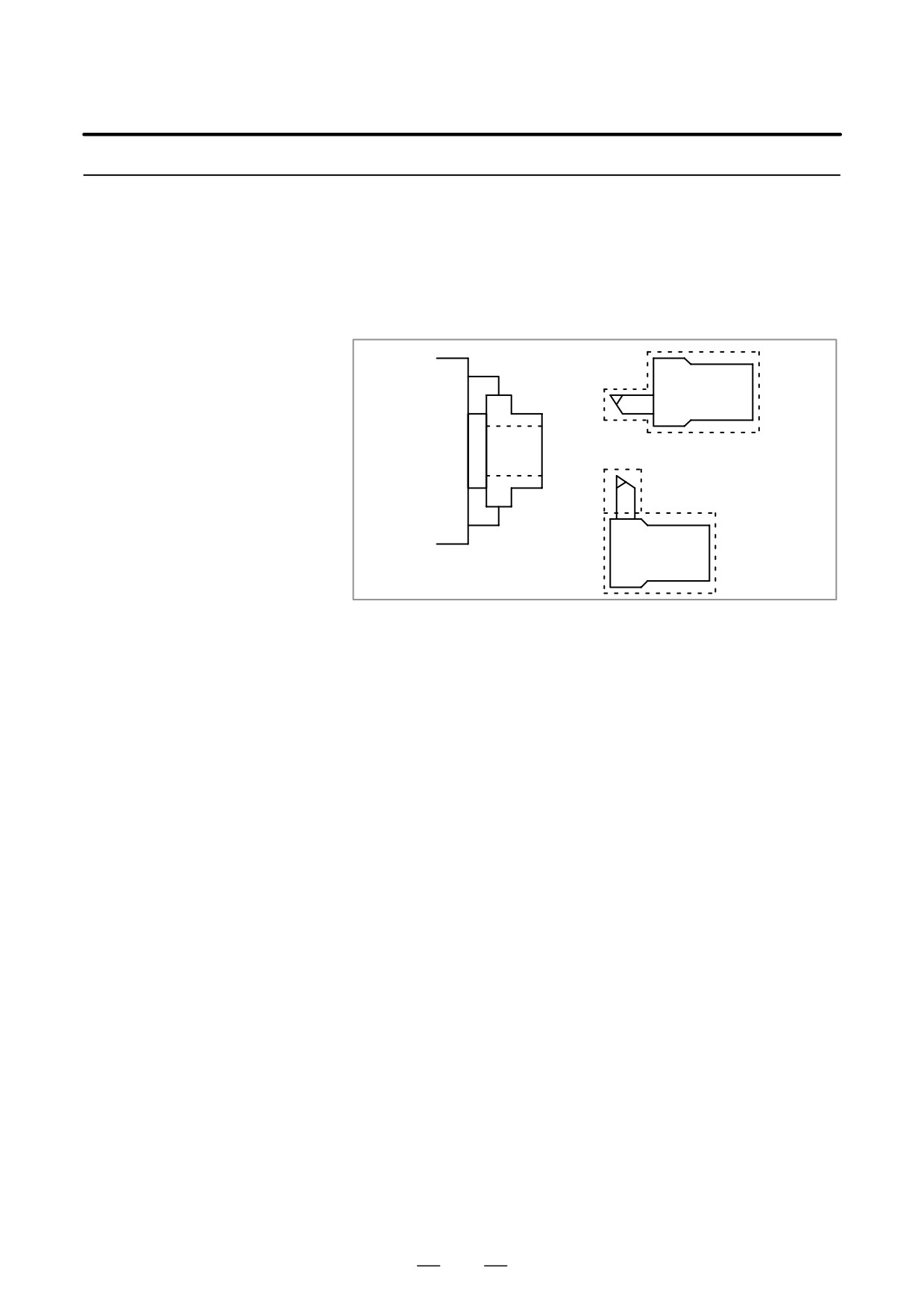
Tool post 1
Tool post 2
When interface forbidden areas (tool shapes) as indicated by dashed lines
are set for tool posts 1 and 2 as shown above, a check is made by
determining whether the two interference forbidden areas indicated by
dashed lines overlap each other after the movement of the tool posts.
If the two areas interfere with each other an P/S alarm (No. 508 or No. 509)
is raised;the two tool posts are decelerated and stopped.
If an interference alarm is raised, a tool post interference alarm signal is
output to the PMC.
If an interference alarm is raised by the interference of the two tool posts
during automatic operation, switch to manual mode to move the tool posts
out of the interference state. Then release the alarm by a reset.
The interference check function can be enabled even in manual mode by
setting the parameter (No. 8140#3) to 1. This allows the tool posts
interfering with each other to be moved along the axes only in such
directions that clear the interference. With this capability, the two tool
posts interfering with each other in automatic operation cannot be
manually moved by mistake further into the interference forbidden areas
after the mode is switched to manual mode to clear the interference, thus
providing safety.
408

20. TWO-PATH CONTROL
B-63524EN/01
PROGRAMMING
FUNCTION
WARNING
When an alarm is raised, the CNC system and machine
system stop with some delay in time.
So an actual stop position can be closer to the other tool
post beyond an interference forbidden position specified
using tool shape data. So, for safety, tool shape data a little
larger than the actual shape should be set. The extra
distance, L, required for this purpose is calculated form a
rapid traverse feedrate as follows
1
L= (Rapid traverse feedrate) ×
7500
For example, when a rapid traverse feedrate of 15 m/min is
used, L=2mm.
CAUTION
When parameters and interface forbidden areas are set to
use the interference check function, be sure to check that
correct interference forbidden areas are set. For this
purpose, set manual mode, and cause the tool posts to
interfere with each other in various directions.
409
20. TWO-PATH CONTROL
FUNCTION
PROGRAMMING
B-63524EN/01
20.3.6
Example of Making a
Tool Post Interference
Check
Explanations
Metric input with metric machine tool
215mm
Tool post 1
+X
115mm
170mm
115mm
Coordinate
T0202
system of tool
75mm
post 1
115mm
0
+Z
0
+Z
200mm
400mm
140mm
100mm
Coordinate system
of tool post 2
60mm
170mm
80mm
T1515
+X
120mm
Tool post 2
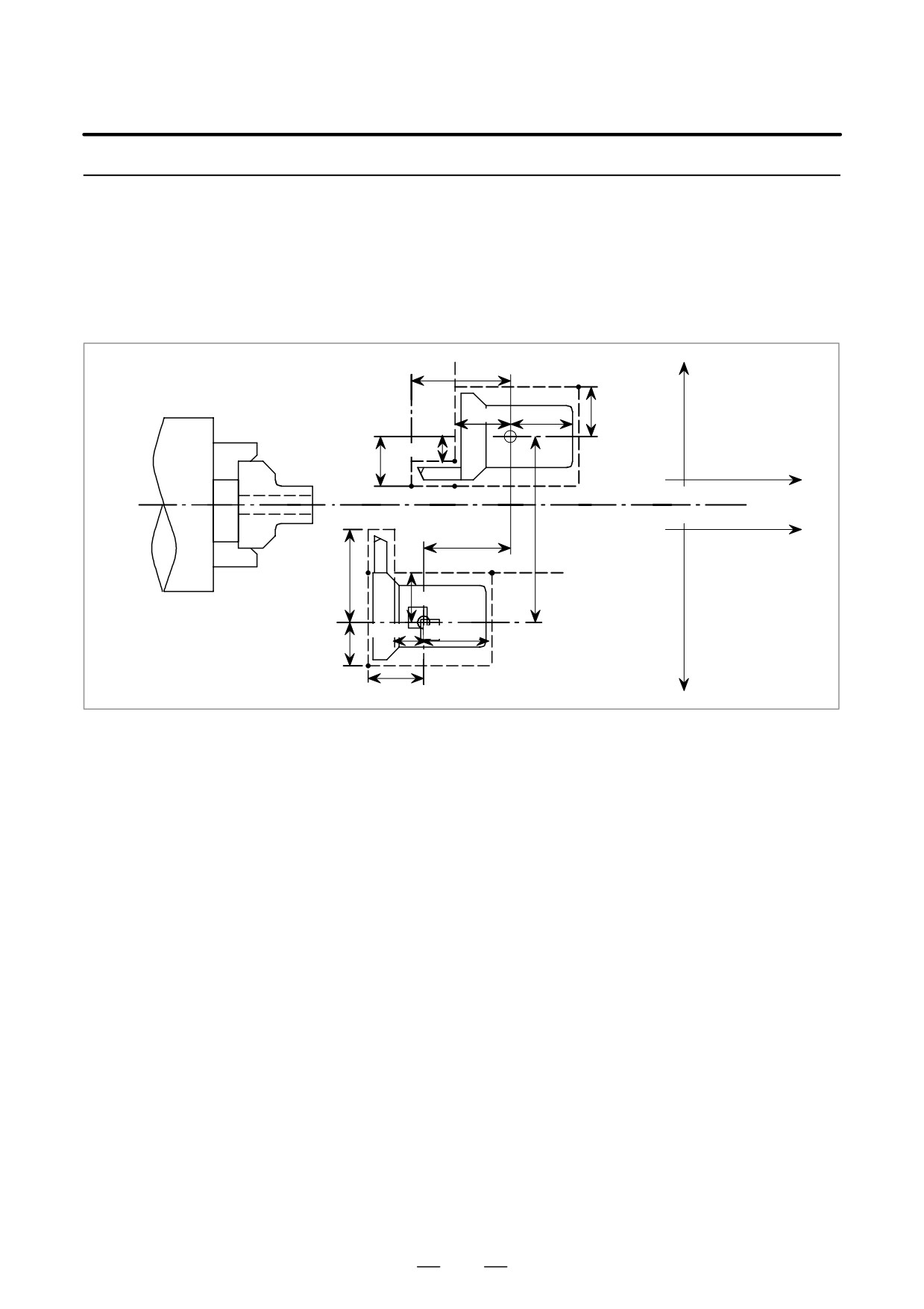
The coordinate systems shown on the right of the figure above are the ZX
plane coordinate systems of tool posts 1 and 2. For clarity, the coordinate
systems are shifted; actually, the origins of the coordinate systems must
match the machine zero points.
Assume the machine configuration shown above. Assume also that offset
number 02 is assigned to tool post 1, and offset number 15 is assigned to
tool post 2.
Suppose that the figure represents the state of reference point return
operation completed with all axes (X1,Z1, X2, Z2). Then set -800
mm(diameter) and
-200 mm in parameter Nos.
8151 and
8152,
respectively.
The positional relationship of the two tool posts matches type (4)
indicated in Section 20.3.2. So set parameters TY0 and TY1 (No.8140#0,
#1) as follows:
Parameter TY1 (No.8140#1)=1
Parameter TY0 (No.8140#0)=1
Then set tool shape data (interference forbidden area) for each tool post.
410
20. TWO-PATH CONTROL
B-63524EN/01
PROGRAMMING
FUNCTION
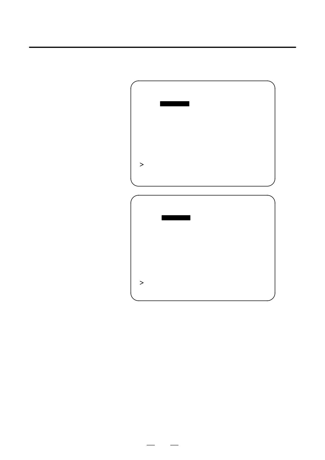
The figures below show the setting of data for tool number 02 assigned
to tool post 1 and for tool number 15 assigned to tool post 2.
TOOL FORM DATA
O0001 N00001
OFFSET NO.
= 01
AREA 1
AREA 2
X=
20.000
X=
40.000
Z=
70.000
Z=
70.000
I=
-10.000
I=
20.000
K=
-50.000
K=
30.000
OFFSET NO.
= 02
AREA 1
AREA 2
X=
115.000
X=
-75.000
Z=
170.000
Z=
-115.000
I=
-115.000
J=
-115.000
K=
-115.000
K=
-215.000
_
S
0 T0000
MEM
12:02:08
HEAD 1
* * * *
* * *
* * *
[ NO.SRH ][
][
][ +INPUT ][ INPUT ]
TOOL FORM DATA
O0001 N00001
OFFSET NO.
= 15
AREA 1
AREA 2
X=
80.000
X=
-100.000
Z=
170.000
Z=
-60.000
I=
-100.000
I=
-140.000
K=
-200.000
K=
-120.000
OFFSET NO.
= 16
AREA 1
AREA 2
X=
0.000
X=
0.000
Z=
0.000
Z=
0.000
I=
0.000
I=
0.000
K=
0.000
K=
0.000
_
S
0 T0000
MEM
* * * *
* * *
* * *
12:02:36
HEAD 2
[ NO.SRH ][
][
][ +INPUT ][ INPUT ]
Set data for other tools similarly. A preparation for an interference check
is completed when data has been set for all tools. Turn on power. Then,
an interference check is started when a T code is specified with each tool
post
after reference point return operation is completed with all of the four axes
(X1, Z1, X2, Z2).
411
20. TWO-PATH CONTROL
FUNCTION
PROGRAMMING
B-63524EN/01
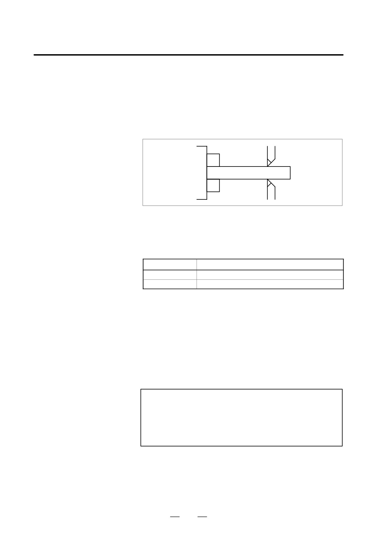
When a thin workpiece is to be machined as shown below, a precision
20.4
machining can be achieved by machining each side of the workpiece with
BALANCE CUT
a tool simultaneously;this function can prevent the workpiece from
(G68, G69)
warpage that can result when only one side is machined at a time. When
both sides are machined at the same time, the movement of one tool must
be in phase with that of the other tool. Otherwise, the workpiece can
vibrate, resulting in poor machining. With this function, the movement
of one tool post can be easily synchronized with that of the other tool post.
Fig. 20.4 Balance cut
Explanations
When G68 is specified in the programs for both tool post 1 and tool post
2, the pulse distribution of tool post 1 is synchronized with that of tool
post 2 to start balance cutting. Thus the two tool posts can move exactly
at the same time to allow balance cutting.
G code
Meaning
G68
Balance cut mode
G69
Balance cut mode cancel
In the balance cut mode, balance cutting is performed only when a move
command is specified for both tool posts. Balance cutting is performed
even when different axes are specified for each tool post or an offset move
command is specified. G68 or G69 must be specified in a single block.
(Otherwise, a P/S alarm (No. 163) is raised. When G68 or G69 is
specified with one tool post, the tool post does not move until the
execution for the other tool post proceeds to G68 or G69. And if cutting
is specified with one tool post in the balance cut mode, the tool post does
not move until the execution of or the other tool post proceeds to a cutting
command.
CAUTION
Balance cut only starts cutting feed on both tool posts at the
same time; it does not maintain synchronization thereafter.
To synchronize all the movements of both tool posts, the
setting for both tool posts, such as the travel distance and
feedrate, must be the same.
412
20. TWO-PATH CONTROL
B-63524EN/01
PROGRAMMING
FUNCTION
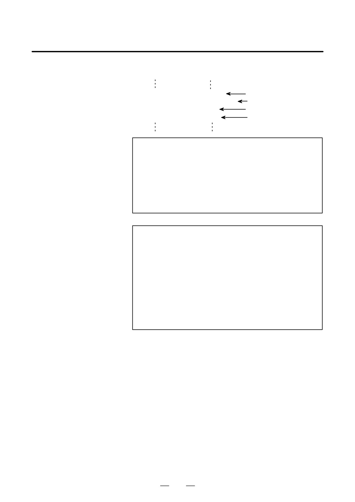
Example
Tool post 1 program Tool post 2 program
G68 ;
G68 ;
Balance cut mode
G01Z100.0 ;
G01Z100.0 ;
Balance cut
Z0 ;
Z0 ;
Balance cut
G69 ;
G69 ;
Balance cut mode
cancel
CAUTION
1
Balance cutting is not performed in dry run or machine lock
state.
2
When rapid traverse operation is specified, balance cut
processing is not performed.
3
A workpiece for which thread cutting has been performed in
the balance cut mode cannot be subjected to thread cutting
in the cancel mode. Thread cutting starts at a different
position.
NOTE
1
Time delay before the pulse distribution of both tool posts
is started is 2 msec or shorter.
2
In the balance cut mode, synchronization is established at
the start of a move block, so movement can momentarily
stop.
3
If feed hold operation is performed during balance cutting
using both tool posts, balance cut processing is not
performed at restart time, it is performed when the next
move command is specified for both tool posts.
4
The cancel mode (G69) is set by a reset.
5
When the option
“mirror image for double turrets” is
selected, the balance cut function cannot be used.
413
20. TWO-PATH CONTROL
FUNCTION
PROGRAMMING
B-63524EN/01
A machine with two tool posts has different custom macro common
20.5
variables and tool compensation memory areas for tool posts 1 and 2.
MEMORY COMMON
Tool posts 1 and 2 can share the custom macro common variables and tool
TO TOOL POSTS
compensation memory areas provided certain parameters are specified
accordingly.
Explanations
D Custom macro common
Tool posts 1 and 2 can share all or part of custom macro common variables
variables
#100 to #149 and #500 to #531, provided parameters 6036 and 6037 are
specified accordingly.
(The data for the shared variables can be written
or read from either tool post.) See Section 15.1 of Part II.
D Tool compensation
Tool post 2 can reference or specify the data in the tool compensation
memory
memory area of tool post 1, provided the CMF bit (bit 5 of parameter
8100) is specified accordingly. This can be executed only when tool posts
1 and 2 have identical data for tool compensation (number of groups,
number of columns, unit system, etc.).
414
20. TWO-PATH CONTROL
B-63524EN/01
PROGRAMMING
FUNCTION
The two-path control function supports two spindle interfaces. Thus,
20.6
16-TB can control a lathe that simultaneously machines a workpiece
SPINDLE CONTROL
attached to one spindle with two tool posts, or can control a lathe that
IN TWO-PATH
simultaneously machines a workpiece attached to each of two spindles
CONTROL
with two tool posts.
The former spindle control is referred to as 1-spindle control, and the
latter is referred to as 2-spindle control.
Parameter 2SP (No. 3703#0) is used to select 1-spindle control or
2-spindle control.
Explanations
D
1-spindle control
One spindle is controlled by programmed commands for tool post 1 or
tool post 2. Programmed commands(Note 1) for the spindle can be
specified from either tool post. However, a spindle speed output selection
signal (Note 2) determines which commands from the two tool posts are
valid. The spindle is controlled according to the commands from a tool
post selected by the signal.
A feedback pulse signal from the position coder attache to the spindle is
applied to both tool posts. Such a feedback pulse signal is used for
processing such as thread cutting and feed per rotation with each tool post.
D
2-spindle control
Two spindles, spindle
1 and spindle
2
(Note
3), are controlled
independently of each other according to programmed commands (Note
1) for each tool post. Usually, programmed commands for tool post 1 are
used to control spindle 1, and programmed commands for tool post 2 are
used to control spindle 2. Feedback pulse signals from the position coders
attached to spindle 1 and spindle 2 are applied to tool post 1 and tool post
2, respectively.
The spindle speed output selection signal (Note 2) can be used to specify
which spindle must be controlled by programmed commands for which
tool post. In addition, a spindle feedback input selection signal (Note 2)
can be used to specify which spindle must be controlled by programmed
commands for which tool post. In addition, a spindle feedback input
selection signal (Note 2) can be used to specify which tool post must
receieve a feedback signal from which spindle. Thus, tool post 1 can
control spindle 2, and tool post 2 can control spindle 1.
415

20. TWO-PATH CONTROL
FUNCTION
PROGRAMMING
B-63524EN/01
NOTE
1
The programmed commands for spindles include the
following.
⋅ S code to specify a spindle speed
⋅ M03
(forward spindle rotation), M04
(reverse spindle
rotation)
⋅ Commands for constant surface speed control (G96, G97,
S code to specify surface speeds, commands to specify
maximum spindle speeds)
2
Refer to the CONNECTION MANUAL (FUNCTION) for
detailed information about the spindle speed output
selection signal and spindle feedback input selection signal.
Control over these signals varies from one machine tool
builder to another. So be sure to read the relevant manual
prepared by the machine tool builder to be familiar with the
commands for the spindles.
3
The spindle connected to spindle interface 1 (main CPU
board) is defined as spindle 1, and the spindle connected to
spindle interface 2 (optional board 2) is defined as spindle 2.
For detail refer to CONNECTION MANUAL (FUNCTION).
416
20. TWO-PATH CONTROL
B-63524EN/01
PROGRAMMING
FUNCTION
In 2-paths control, the synchronization control function and composite
20.7
control function enable synchronization control in a single system or
SYNCHRONIZATION
between two systems, composite control of two systems, and
CONTROL AND
superposition control of two systems.
COMPOSITE
CONTROL
Explanations
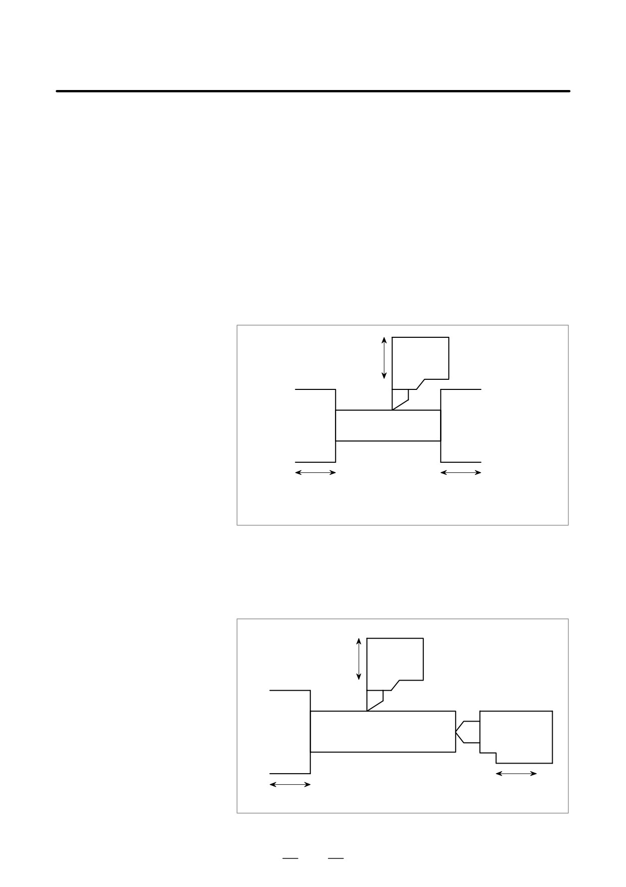
D Synchronization control
Synchronizes movement along an axis of one system with that along an
axis of the other system.
Example)
Synchronizing movement along the Z1 and Z2 axes
Turret 1
X1
Workpiece
Z1
Z2 (Synchronized with move-
ment along the Z1 axis)
Machining according to a program for system 1
Synchronizes movement along an axis of one system with that along
another axis of the same system.
Example)
Synchronizing movement along the Z1 and B1 axes
Turret 1
X1
Tail stock
Workpiece 1
B1 (Synchronized with move-
Z1
ment along the Z1 axis)
417
20. TWO-PATH CONTROL
FUNCTION
PROGRAMMING
B-63524EN/01
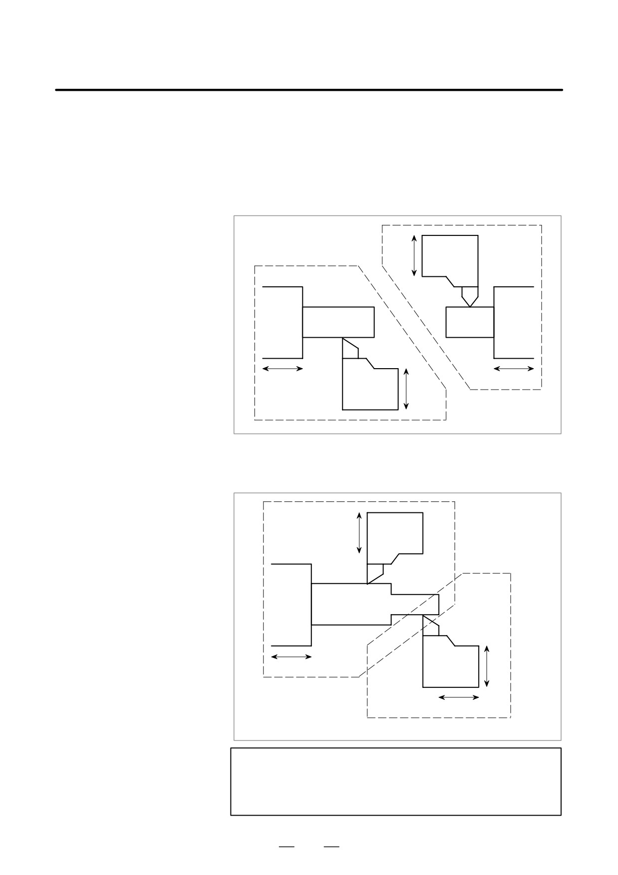
D Composite control
Exchanges the move commands for different axes of different systems.
Example)
Exchanging the commands for the X1 and X2 axes
-> Upon the execution of a command programmed for system 1,
movement is performed along the X2 and Z1 axes.
Upon the execution of a command programmed for system 2,
movement is performed along the X1 and Z2 axes.
Machining according to a
Turret 1
X1
program for system 1
Workpiece 1
Work-
piece 2
Z1
Z2
X2
Turret 2
Machining accord-
ing to a program for
system 2
D Superposition control
Provides a move command of an axis for a different axis in another system.
Example)
Providing the Z2 axis with a move command specified for the Z1 axis
Machining according
to a program for sys-
Turret 1
tem 1
X1
Workpiece 1
Z1
Turret 2
X2
Work-
piece 2
Z2
Machining according to a program
for system 2
NOTE
The method used to specify synchronization or composite
control varies with the machine tool builder. For details,
refer to the manual supplied by the machine tool builder.
418
20. TWO-PATH CONTROL
B-63524EN/01
PROGRAMMING
FUNCTION
In a CNC supporting two-path control, specified machining programs
20.8
can be copied between the two paths by setting bit 0 (PCP) of parameter
COPYING A
No. 3206 to 1. A copy operation can be performed by specifying either
PROGRAM
a single program or a range. For information about operations, see
BETWEEN TWO
Section 9.10 in Part III.
PATHS
Explanations
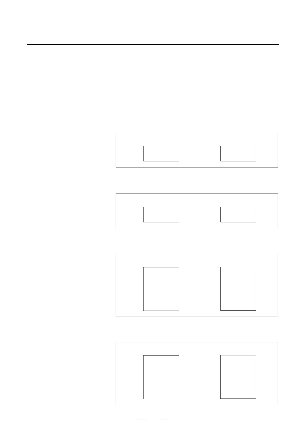
D Single-program copy
Copy source number: 0001
Copy destination number: Not set
Copy source
Copy destination
O0001
³
O0001
Copy source number: 0001
Copy destination 0010
Copy source
Copy destination
O0001
³
O0010
D Specified-range copy
Copy source number: 0001 to 0100
Copy destination number: Not set
Copy source
Copy destination
O0001
³
O0001
O0010
³
O0010
O0100
³
O0100
O1000
O2000
Copy source number: 0001 to 0100
Copy destination 1000
Copy source
Copy destination
O0001
³
O1001
O0010
³
O1001
O0100
³
O1002
O1000
O2000
419
21. PATTERN DATA INPUT
FUNCTION
PROGRAMMING
B-63524EN/01
PATTERN DATA INPUT FUNCTION
21
This function enables users to perform programming simply by extracting
numeric data (pattern data) from a drawing and specifying the numerical
values from the MDI panel.
This eliminates the need for programming using an existing NC language.
With the aid of this function, a machine tool builder can prepare the
program of a hole machining cycle (such as a boring cycle or tapping
cycle) using the custom macro function, and can store it into the program
memory.
This cycle is assigned pattern names, such as BOR1, TAP3, and DRL2.
An operator can select a pattern from the menu of pattern names displayed
on the screen.
Data (pattern data) which is to be specified by the operator should be
created in advance with variables in a drilling cycle.
The operator can identify these variables using names such as DEPTH,
RETURN RELIEF, FEED, MATERIAL or other pattern data names. The
operator assigns values (pattern data) to these names.
420
21. PATTERN DATA INPUT
B-63524EN/01
PROGRAMMING
FUNCTION
21.1
OFFSET
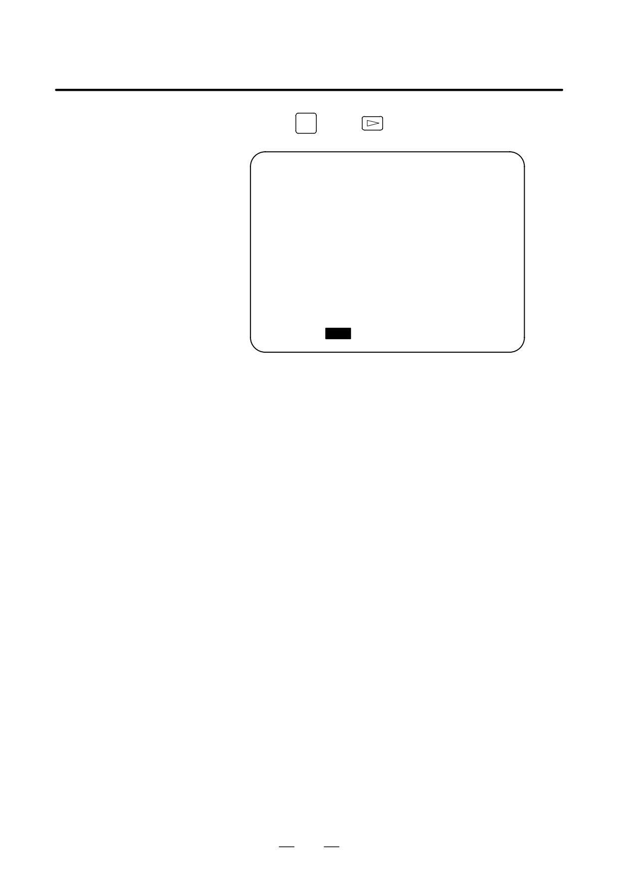
Pressing the
SETTING
key and
[MENU] is displayed on the following
DISPLAYING THE
pattern menu screen.
PATTERN MENU
MENU : HOLE PATTERN
O0000 N00000
1. TAPPING
2. DRILLING
3. BORING
4. POCKET
5. BOLT HOLE
6. LINE ANGLE
7. GRID
8. PECK
9. TEST PATRN
10. BACK
> _
MDI **** *** ***
16:05:59
[ MACRO ] [
MENU
] [ OPR
] [
] [(OPRT)]
HOLE PATTERN :
This is the menu title. An arbitrary character string consisting of up
to 12 characters can be specified.
BOLT HOLE :
This is the pattern name. An arbitrary character string consisting of
up to 10 characters can be specified, including katakana.
The machine tool builder should specify the character strings for the menu
title and pattern name using the custom macro, and load the character
strings into program memory as a subprogram of program No. 9500.
421

21. PATTERN DATA INPUT
FUNCTION
PROGRAMMING
B-63524EN/01
D Macro commands
Menu title : C1 C2 C3 C4 C5 C6 C7 C8 C9C10 C11 C12
specifying the menu
C1,C2,,C12 : Characters in the menu title (12 characters)
title
Macro instruction
G65 H90 Pp Qq Rr Ii Jj Kk :
H90:Specifies the menu title
p : Assume a1 and a2 to be the codes of characters C1 and C2. Then,
Pfff
fff
Code a2 of character C2
Code a1 of character C1
q : Assume a3 and a4 to be the codes of characters C3 and C4. Then,
q=a3 103+a4
r : Assume a5 and a6 to be the codes of characters C5 and C6. Then,
r=a5 103+a6
i : Assume a7 and a8 to be the codes of characters C7 and C8. Then,
i=a7 103+a8
j : Assume a9 and a10 to be the codes of characters C9 and C10. Then,
j=a9 103+a10
k : Assume a11 and a12 to be the codes of characters C11 and C12. Then,
k=a11 103+a12
Example)
If the title of the menu is
“HOLE PATTERN” then the macro
instruction is as follows:
G65 H90 P072079 Q076069 R032080
HO LE
P
I065084 J084069 K082078;
AT
TE
RN
For codes corresponding to these characters, refer to the table in
II-21.3.
422

21. PATTERN DATA INPUT
B-63524EN/01
PROGRAMMING
FUNCTION
D Macro instruction
Pattern name: C1 C2 C3 C4 C5 C6 C7 C8 C9C10
describing the pattern
C1, C2, ,C10: Characters in the pattern name (10 characters)
name
Macro instruction
G65 H91 Pn Qq Rr Ii Jj Kk ;
H91: Specifies the menu title
n : Specifies the menu No. of the pattern name
n=1 to 10
q : Assume a1 and a2 to be the codes of characters C1 and C2. Then,
q=a1 103+a2
r : Assume a3 and a4 to be the codes of characters C3 and C4. Then,
r=a3 103+a4
i : Assume a5 and a6 to be the codes of characters C5 and C6. Then,
i=a5 103+a6
j : Assume a7 and a8 to be the codes of characters C7 and C8. Then,
j=a7 103+a8
k : Assume a9 and a10 to be the codes of characters C9 and C10. Then,
k=a9 103+a10
Example)
If the pattern name of menu No. 1 is “BOLT HOLE” then the macro
instruction is as follows.
G65 H91 P1 Q066079 R076084 I032072 J079076 K069032 ;
BO
LT
H OL
E
D Pattern No. selection
To select a pattern from the pattern menu screen, enter the corresponding
pattern No. The following is an example.
1
INPUT
The selected pattern No. is assigned to system variable #5900. The
custom macro of the selected pattern can be started by starting a fixed
program (external program No. search) with an external signal then
referring to the system variable #5900 in the program.
NOTE
If each characters of P, Q, R, I, J, and K are not specified in
a macro instruction, two spaces are assigned to each
omitted character.
423
21. PATTERN DATA INPUT
FUNCTION
PROGRAMMING
B-63524EN/01
Example
Custom macros for the menu title and hole pattern names.
MENU : HOLE PATTERN
O0000 N00000
1. TAPPING
2. DRILLING
3. BORING
4. POCKET
5. BOLT HOLE
6. LINE ANGLE
7. GRID
8. PECK
9. TEST PATRN
10. BACK
> _
MDI **** *** ***
16:05:59
[ MACRO ] [
MENU ] [ OPR ] [
] [ (OPRT) ]
O9500 ;
N1G65 H90 P072 079 Q076 069 R032 080 I 065 084 J 084 069 K082 078 ; HOLE PATTERN
N2G65 H91 P1 Q066 079 R076 084 I 032 072 J 079 076 K069 032 ;
1.BOLT HOLE
N3G65 H91 P2 Q071 082 R073 068 ;
2.GRID
N4G65 H91 P3 Q076 073 R078 069 I 032 065 J 078071 K076069 ;
3.LINE ANGLE
N5G65 H91 P4 Q084 065 R080 080 I 073 078 J 071 032 ;
4.TAPPING
N6G65 H91 P5 Q068 082 R073 076 I 076 073 J 078 071 ;
5.DRILLING
N7G65 H91 P6 Q066079 R082073 I 078 071 ;
6.BORING
N8G65 H91 P7 Q080 079 R067 075 I 069 084 ;
7.POCKET
N9G65 H91 P8 Q080069 R067075 ;
8.PECK
N10G65 H91 P9 Q084 069 R083 084 I032 080 J065 084 K082 078 ;
9.TEST PATRN
N11G65 H91 P10 Q066 065 R067 0750 ;
10.BACK
N12M99 ;
424
21. PATTERN DATA INPUT
B-63524EN/01
PROGRAMMING
FUNCTION
When a pattern menu is selected, the necessary pattern data is displayed.
21.2
PATTERN DATA
VAR. : BOLT HOLE
O0001 N00000
DISPLAY
NO. NAME
DATA
COMMENT
500
TOOL
0.000
501
STANDARD X
0.000
*BOLT HOLE
502
STANDARD Y
0.000
CIRCLE*
503
RADIUS
0.000
SET PATTERN
504
S. ANGL
0.000
DATA TO VAR.
505
HOLES NO
0.000
NO.500-505.
506
0.000
507
0.000
ACTUAL POSITION (RELATIVE)
X
0.000
Y
0.000
Z
0.000
> _
MDI **** *** ***
16:05:59
[ MACRO ] [ MENU ] [
OPR
] [
] [(OPRT)]
BOLT HOLE :
This is the pattern data title. A character string consisting of up to 12
characters can be set.
TOOL
:
This is the variable name. A character string consisting of up to 10
characters can be set.
*BOLT HOLE CIRCLE* :
This is a comment statement. A character string can be displayed
consisting of up to 8 lines, 12 characters per line.
(It is permissible to use katakana in a character string or line.)
The machine tool builder should program the character strings of pattern
data title, pattern name, and variable name using the custom macro, and
load them into the program memory as a subprogram whose No. is 9500
plus the pattern No. (O9501 to O9510).
425
21. PATTERN DATA INPUT
FUNCTION
PROGRAMMING
B-63524EN/01
D Macro instruction
Menu title : C1 C2 C3 C4 C5 C6 C7 C8 C9C10C11C12
specifying the pattern
C1 ,C2,…, C12 : Characters in the menu title (12 characters)
data title
Macro instruction
(the menu title)
G65 H92 Pn Qq Rr Ii Jj Kk ;
H92 : Specifies the pattern name
p : Assume a1 and a2 to be the codes of characters C1 and C2. Then,
p=a1 103+a2
See 17.3 for character codes.
q : Assume a3 and a4 to be the codes of characters C3 and C4. Then,
q=a3 103+a4
r : Assume a5 and a6 to be the codes of characters C5 and C6. Then,
r=a5 103+a6
i : Assume a7 and a8 to be the codes of characters C7 and C8. Then,
i=a7 103+a8
j : Assume a9 and a10 to be the codes of characters C9 and C10. Then,
j=a9 103+a10
k : Assume a11 and a12 to be the codes of characters C11 and C12. Then,
k=a11 103+a12
Example)
Assume that the pattern data title is “BOLT HOLE.” The macro
instruction is given as follows:
G65 H92 P066079 Q076084 R032072 I079076 J069032;
BO
LT
H OL
E
D Macro instruction
Variable name : C1 C2 C3 C4 C5 C6 C7 C8 C9 C10
specifying the variable
C1, C2,…, C10 : Characters in the variable name (10 characters)
name
Macro instruction
G65 H93 Pn Qq Rr Ii Jj Kk ;
H93 : Specifies the variable name
n : Specifies the menu No. of the variable name
n=1 to 10
q : Assume a1 and a2 to be the codes of characters C1 and C2. Then,
q=a1 103+a2
r : Assume a3 and a4 to be the codes of characters C3 and C4. Then,
r=a3 103+a4
i : Assume a5 and a6 to be the codes of characters C5 and C6. Then,
i=a5 103+a6
j : Assume a7 and a8 to be the codes of characters C7 and C8. Then,
j=a7 103+a8
k : Assume a9 and a10 to be the codes of characters C9 and C10. Then,
k=a9 103a+a10
Example)
Assume that the variable name of the variable No. 503 is “RADIUS.”
The macro instruction is given as follows:
G65 H93 P503 Q082065 R068073 I085083 ;
RA
DI
US
426
21. PATTERN DATA INPUT
B-63524EN/01
PROGRAMMING
FUNCTION
D Macro instruction to
One comment line: C1 C2 C3 C4 C5 C6 C7 C8 C9 C10 C11 C12
describe a comment
C1, C2,…, C12 : Character string in one comment line (12 characters)
Macro instruction
G65 H94 Pn Qq Rr Ii Jj Kk ;
H94 : Specifies the comment
p : Assume a1 and a2 to be the codes of characters C1 and C2. Then,
p=a1 103+a2
See 17.7 for character codes.
q : Assume a3 and a4 to be the codes of characters C3 and C4. Then,
q=a3 103+a4
r : Assume a5 and a6 to be the codes of characters C5 and C6. Then,
r=a5 103+a6
i : Assume a7 and a8 to be the codes of characters C7 and C8. Then,
i=a7 103+a8
j : Assume a9 and a10 to be the codes of characters C9 and C10. Then,
j=a9 103+a10
k : Assume a11 and a12 to be the codes of characters C11 and C12. Then,
k=a11 103+a12
A comment can be displayed in up to eight lines. The comment consists
of the first line to the eighth line in the programmed sequence of G65 H94
for each line.
Example)
Assume that the comment is “BOLT HOLE.” The macro instruction
is given as follows:
G65 H94 P042066 Q079076 R084032 I072079 J076069;
*B
OL
T
HO LE
427
21. PATTERN DATA INPUT
FUNCTION
PROGRAMMING
B-63524EN/01
Examples
Macro instruction to describe a parameter title , the variable name, and
a comment.
VAR. : BOLT HOLE
O0001 N00000
NO. NAME
DATA
COMMENT
500
TOOL
0.000
501
STANDARD X
0.000
*BOLT HOLE
502
STANDARD Y
0.000
CIRCLE*
503
RADIUS
0.000
SET PATTERN
504
S. ANGL
0.000
DATA TO VAR.
505
HOLES NO
0.000
NO.500-505.
506
0.000
507
0.000
ACTUAL POSITION (RELATIVE)
X
0.000
Y
0.000
Z
0.000
> _
MDI **** *** ***
16:05:59
[ MACRO ] [ MENU ] [
OPR
] [
] [(OPRT)]
O9501 ;
N1G65 H92 P066 079 Q076 084 R032 072 I 079 076 J069 032 ;
VAR : BOLT HOLE
N2G65 H93 P500 Q084 079 R079076 ;
#500 TOOL
N3G65 H93 P501 Q075 073 R074 085 I078 032 J088 032 ;
#501 KIJUN X
N4G65 H93 P502 Q075 073 R074 085 I 078 032 J089 032 ;
#502 KIJUN Y
N5G65 H93 P503 Q082 065 R068 073 I 085 083 ;
#503 RADIUS
N6G65 H93 P504 Q083 046 R032 065 I 078 071 J 076 032 ;
#504 S.ANGL
N7G65 H93 P505 Q072 079 R076 069 I 083 032 J078 079 K046 032 ;
#505 HOLES NO
N8G65 H94 ;
Comment
N9G65 H94 P042 066 Q079 076 R084 032 I072 079 J076 069 ;
*BOLT HOLE
N10G65 H94 R032 067 I073 082 J067 076 K069 042 ;
CIRCLE*
N11G65 H94 P083 069 Q084 032 080 065 I084 084 J069 082 K078 032 ; SET PATTERN
N12G65 H94 P068 065 Q084 065 R032 084 I079 032 J086 065 K082046 ; DATA NO VAR.
N13G65 H94 P078 079 Q046 053 R048 048 I045 053 J048 053 K046 032 ; No.500-505
N14M99 ;
428