FANUC Series Series 16i-TB, Series 18i-TB, Series 160i-TB, Series 180i-TB. OPERATOR’S MANUAL - page 5

B-63524EN/01
PROGRAMMING
7. COORDINATE SYSTEM
A coordinate system used for machining a workpiece is referred to as a
7.2
workpiece coordinate system. A workpiece coordinate system is to be set
WORKPIECE
with the NC beforehand (setting a workpiece coordinate system).
COORDINATE
A machining program sets a workpiece coordinate system (selecting a
SYSTEM
workpiece coordinate system).
A set workpiece coordinate system can be changed by shifting its origin
(changing a workpiece coordinate system).
7.2.1
A workpiece coordinate system can be set using one of three methods:
Setting a Workpiece
(1) Method using G50
A workpiece coordinate system is set by specifying a value after G50
Coordinate System
in the program.
(2) Automatic setting
If bit
0 of parameter No. 1201 is set beforehand, a workpiece
coordinate system is automatically set when manual reference
position return is performed (see III-3.1.).
This function is, however, disabled when the workpiece coordinate
system option is being used.
(3) Input using the MDI panel
Six workpiece coordinate systems can be set beforehand using the
MDI panel.
Program commands G54 to G59 can be used to select the work axis
to be used. (see III-11.4.10.)
When an absolute command is used, a workpiece coordinate system
must be established in any of the ways described above.
Format
D Setting a workpiece
G50 IP_
coordinate system by G50
Explanations
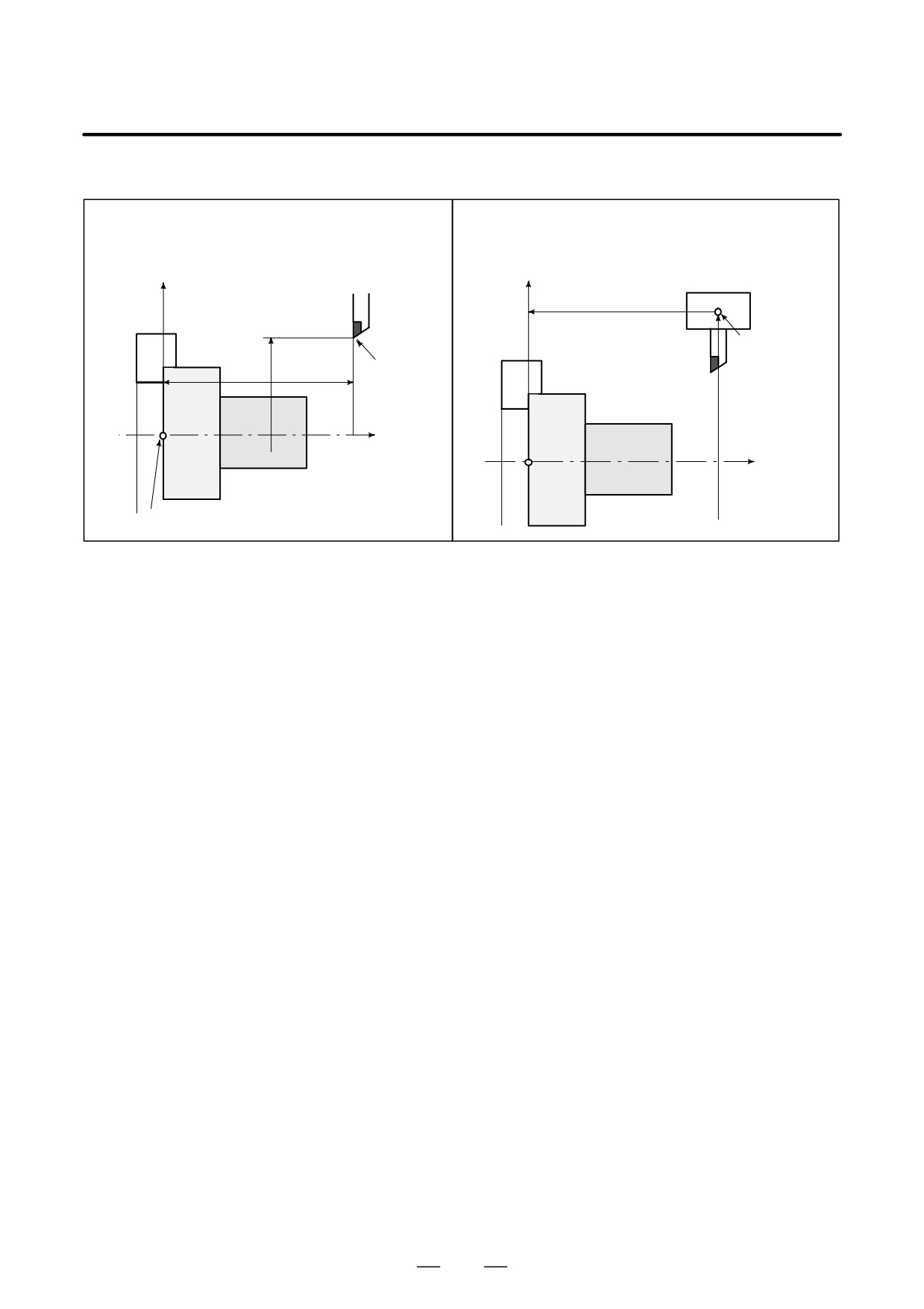
A workpiece coordinate system is set so that a point on the tool, such as
the tool tip, is at specified coordinates. If IP is an incremental command
value, the work coordinate system is defined so that the current tool
position coincides with the result of adding the specified incremental
value to the coordinates of the previous tool position. If a coordinate
system is set using G50 during offset, a coordinate system in which the
position before offset matches the position specified in G50 is set.
99
7. COORDINATE SYSTEM
PROGRAMMING
B-63524EN/01
Examples
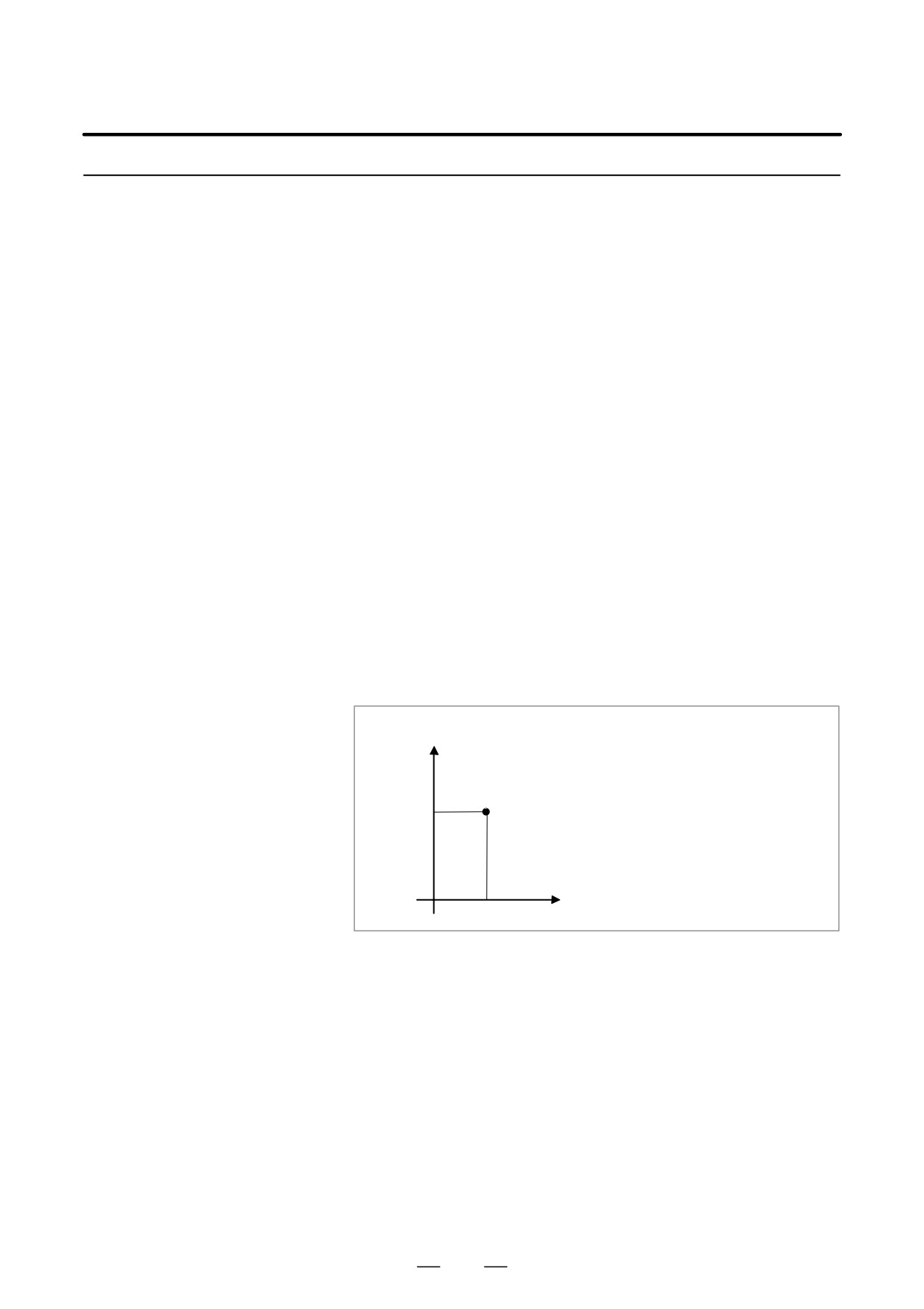
Example 1
Example 2
Base point
Setting the coordinate system by the
Setting the coordinate system by the
G50X128.7Z375.1; command (Diameter designation)
G50X1200.0Z700.0; command (Diameter designation)
X
X
700.0
ÎÎÎ
Start point
ÎÎÎ
(standard point)
ÎÎ
375.1
Start point
ÎÎ
Î
φ128.7
φ1200.0
Î
Z
Z
Zero point
100
B-63524EN/01
PROGRAMMING
7. COORDINATE SYSTEM
7.2.2
The user can choose from set workpiece coordinate systems as described
below.
(For information about the methods of setting, see Subsec.
Selecting a Workpiece
II-7.2.1.)
Coordinate System
(1) G50 or automatic workpiece coordinate system setting
Once a workpiece coordinate system is selected, absolute commands
work with the workpiece coordinate system.
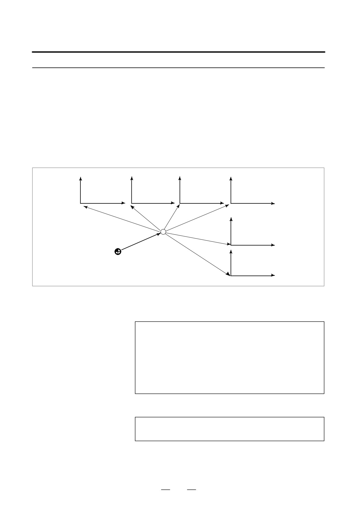
(2) Choosing from six workpiece coordinate systems set using the
MDI
By specifying a G code from G54 to G59, one of the workpiece
coordinate systems 1 to 6 can be selected.
G54 Workpiece coordinate system 1
G55 Workpiece coordinate system 2
G56 Workpiece coordinate system 3
G57 Workpiece coordinate system 4
G58 Workpiece coordinate system 5
G59 Workpiece coordinate system 6
Workpiece coordinate system 1 to 6 are established after reference
position return after the power is turned on. When the power is turned
on, G54 coordinate system is selected.
When bit 2 (G50) of parameter No. 1202 is set to 1, executing the G50
command results in the issue of P/S alarm No. 10. This is designed
to prevent the user from confusing coordinate systems.
Examples
G55 G00 X100.0 Z40.0 ;
X
Workpiece coordinate system 2 (G55)
100.0
In this example, positioning is made to
positions (X=100.0, Z=40.0) in workpiece
coordinate system 2.
40.0
Z
Fig. 7.2.2
101
7. COORDINATE SYSTEM
PROGRAMMING
B-63524EN/01
7.2.3
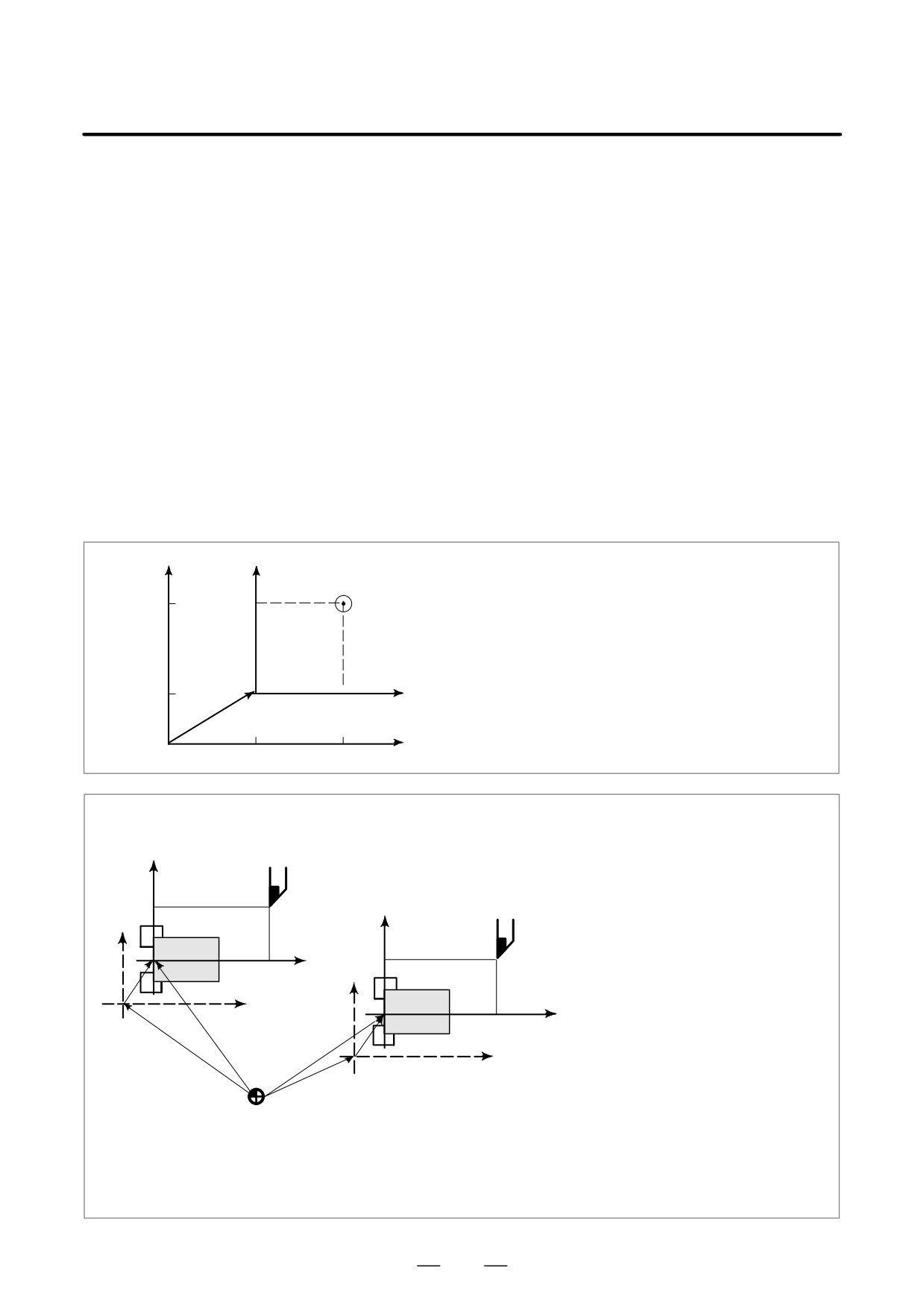
The six workpiece coordinate systems specified with G54 to G59 can be
changed by changing an external workpiece zero point offset value or
Changing Workpiece
workpiece zero point offset value.
Coordinate System
Three methods are available to change an external workpiece zero point
offset value or workpiece zero point offset value.
(1) Inputting from the MDI panel (see III-11.4.10)
(2) Programming by G10 or G50
(3) Using the external data input function
An external workpiece origin offset can be changed by using a signal
input to the CNC. For details, refer to the relevant manual supplied
by the machine tool builder.
Workpiece
Workpiece
Workpiece
Workpiece
coordinate
coordinate
coordinate
coordinate
system 1 (G54)
system 2 (G55)
system 3 (G56)
system 4 (G57)
ZOFS2
ZOFS3
ZOFS1
ZOFS4
Workpiece
coordinate
ZOFS5
system 5 (G58)
EXOFS
ZOFS6
Workpiece
Machine zero
coordinate
system 6 (G59)
EXOFS : External workpiece zero point offset value
ZOFS1 to ZOFS6 : Workpiece zero point offset value
Fig. 7.2.3 Changing an external workpiece zero point offset value or workpiece zero point offset value
Format
G10 L2 Pp IP _;
D Changing by G10
p=0 : External workpiece zero point offset value
p=1 to 6 : Workpiece zero point offset value correspond to
workpiece coordinate system 1 to 6
IP : For an absolute command (G90), workpiece zero point off-
set for each axis.
For an incremental command (G91), value to be added to
the set workpiece zero point offset for each axis (the sum
is set as the new offset).
D Changing by G50
G50 IP _;
102
B-63524EN/01
PROGRAMMING
7. COORDINATE SYSTEM
Explanations
D Changing by G10
With the G10 command, each workpiece coordinate system can be
changed separately.
D Changing by G50
By specifying G50IP_;, a workpiece coordinate system (selected with a
code from G54 to G59) is shifted to set a new workpiece coordinate
system so that the current tool position matches the specified coordinates
(IP_).
If IP is an incremental command value, the work coordinate system is
defined so that the current tool position coincides with the result of adding
the specified incremental value to the coordinates of the previous tool
position.
(Coordinate system shift)
Then, the amount of coordinate system shift is added to all the workpiece
zero point offset values. This means that all the workpiece coordinate
systems are shifted by the same amount.
Examples
XȀ
X
G54 workpiece coordinate system
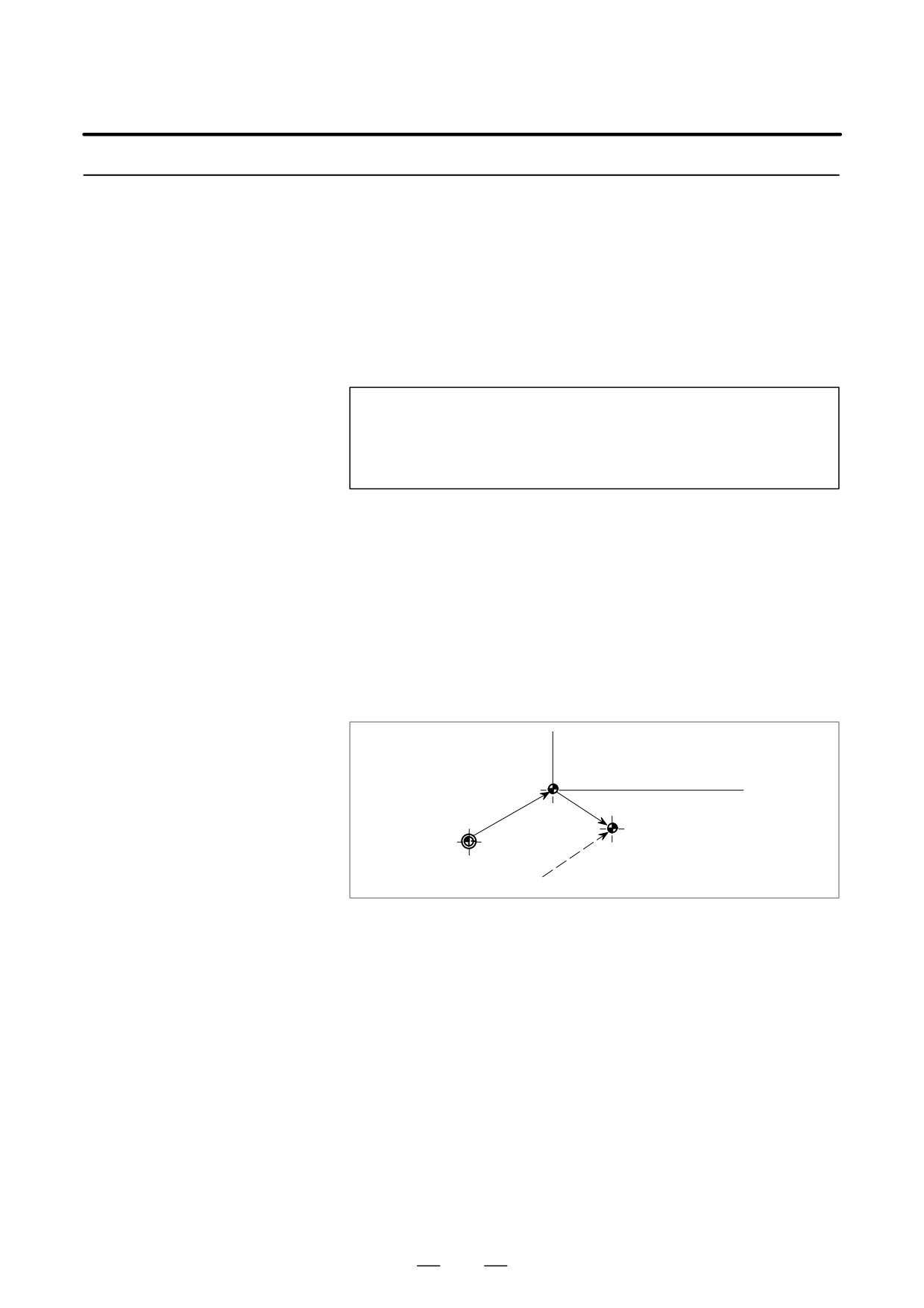
If G50X100Z100; is commanded when the tool
is positioned at (200, 160) in G54 mode, work-
160
100
Tool position
piece coordinate system 1 (X′ - Z′) shifted by
vector A is created.
A
Z′
New workpiece coordinate system
60
100
Z
Original workpiece coordinate system
100
200
<G54 Workpiece coordinate system>
Suppose that a G54 workpiece coordi-
nate system is specified. Then, a G55
X′
workpiece coordinate system where
the black circle on the tool (figure at
<G55 Workpiece coordinate system>
the left) is at (600.0,12000.0) can be
set with the following command if the
X′
600.0
relative relationship between the G54
workpiece coordinate system and
ÎÎ
X
G55 workpiece coordinate system is
Î
Z′
set correctly:G50X600.0Z1200.0;Also,
600.0
1200.0
suppose that pallets are loaded at two
ÎA
ÎÎ
X
different positions. If the relative rela-
ÎÎ
Z
Î
tionship of the coordinate systems of
Z′
the pallets at the two positions is cor-
Î
1200.0
rectly set by handling the coordinate
B
A Î
systems as the G54 workpiece coordi-
Z
nate system and G55 workpiece coor-
dinate system, a coordinate system
C
shift with G50 in one pallet causes the
same coordinate system shift in the
X′ - Z′ New workpiece coordinate system
other pallet. This means that work-
pieces on two pallets can be ma-
X - Z Original workpiece coordinate system
chined with the same program just by
A : Offset value created by G50
B : Workpiece zero point offset value in G54
specifying G54 or G55.
C : Workpiece zero point offset value in G55
103
7. COORDINATE SYSTEM
PROGRAMMING
B-63524EN/01
7.2.4
The workpiece coordinate system preset function presets a workpiece
coordinate system shifted by manual intervention to the pre-shift
Workpiece Coordinate
workpiece coordinate system. The latter system is displaced from the
System Preset (G92.1)
machine zero point by a workpiece zero point offset value.
There are two methods for using the workpiece coordinate system preset
function. One method uses a programmed command (G92.1). The other
uses MDI operations on the absolute position display screen, relative
position display screen, and overall position display screen (III - 11.1.4).
Format
G92.1 IP 0 ;
(G50.3 P0 ; for G code system A)
IP 0 ; Specifies axis addresses subject to the workpiece
coordinate system preset operation. Axes that are
not specified are not subject to the preset operation.
Explanations
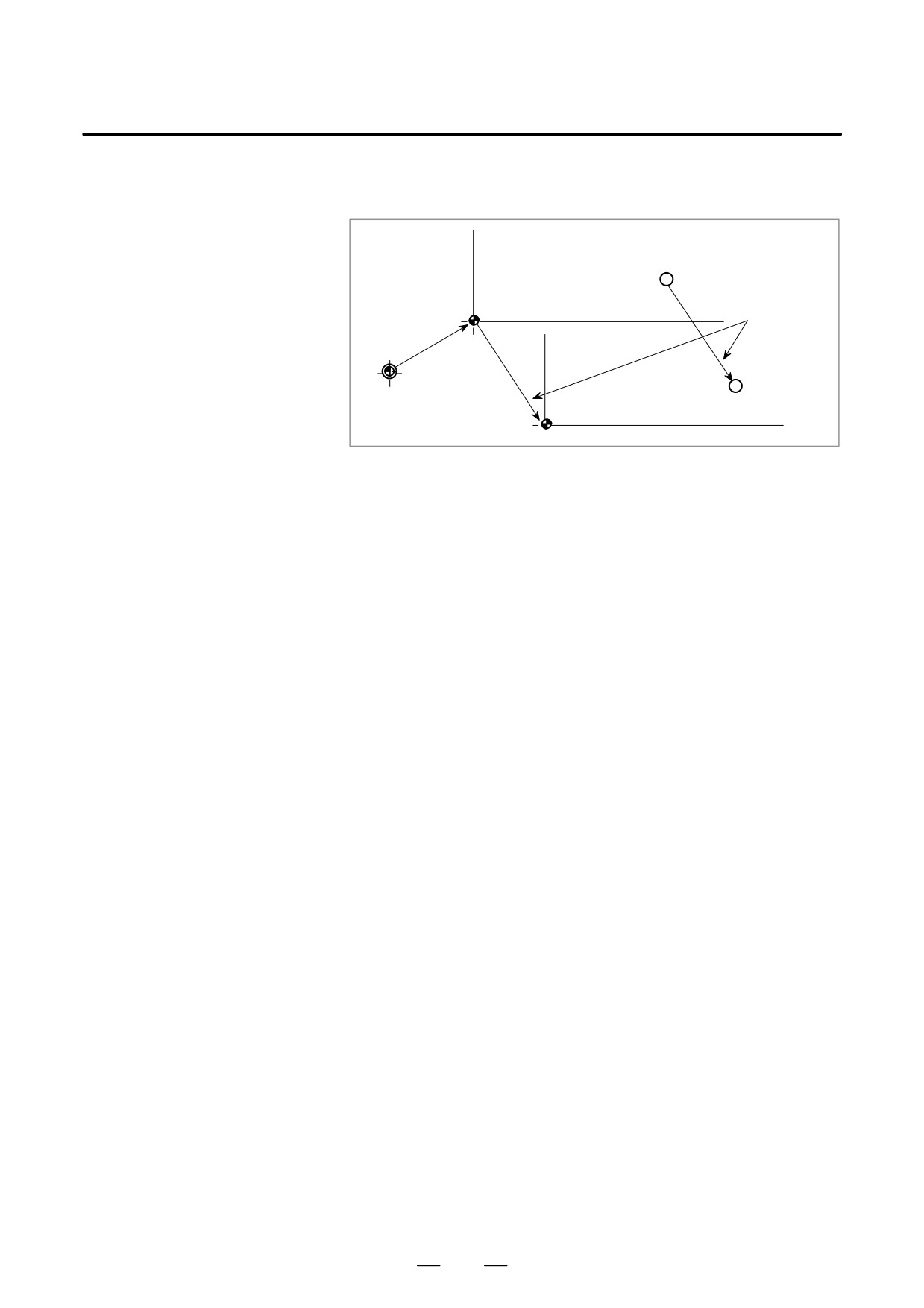
When manual reference position return operation is performed in the reset
state, a workpiece coordinate system is shifted by the workpiece zero
point offset value from the machine coordinate system zero point.
Suppose that the manual reference position return operation is performed
when a workpiece coordinate system is selected with G54. In this case,
a workpiece coordinate system is automatically set which has its zero
point displaced from the machine zero point by the G54 workpiece zero
point offset value; the distance from the zero point of the workpiece
coordinate system to the reference position represents the current position
in the workpiece coordinate system.
G54 workpiece coordinate system
G54 workpiece zero
point offset value
Reference position
Reference position
Manual reference position return
If an absolute position detector is provided, the workpiece coordinate
system automatically set at power-up has its zero point displaced from
the machine zero point by the G54 workpiece zero point offset value. The
machine position at the time of power-up is read from the absolute
position detector and the current position in the workpiece coordinate
system is set by subtracting the G54 workpiece zero point offset value
from this machine position. The workpiece coordinate system set by
these operations is shifted from the machine coordinate system using the
commands and operations listed next page.
(a) Manual intervention performed when the manual absolute signal is off
(b) Move command executed in the machine lock state
(c) Movement by handle interrupt
(d) Operation using the mirror image function
(e) Setting the local coordinate system using G52, or shifting the
workpiece coordinate system using G92
104
B-63524EN/01
PROGRAMMING
7. COORDINATE SYSTEM
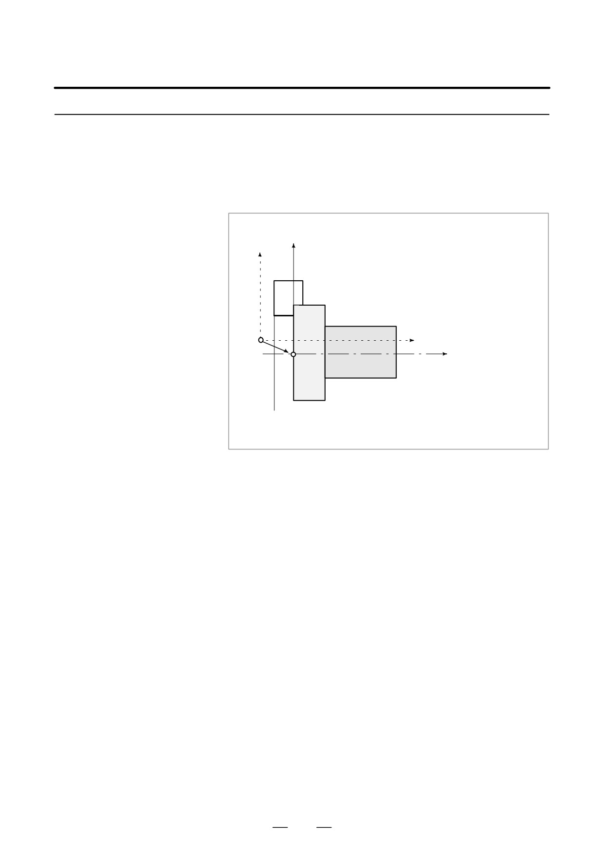
In the case of (a) above, the workpiece coordinate system is shifted by the
amount of movement during manual intervention.
G54 workpiece coordinate
system before manual
Po
intervention
Amount of movement
during manual
Workpiece zero
WZo
intervention
point offset
value
Pn
G54 workpiece coordinate
Machine zero point
system after manual intervention
WZn
In the operation above, a workpiece coordinate system once shifted can
be preset using G code specification or MDI operation to a workpiece
coordinate system displaced by a workpiece zero point offset value from
the machine zero point. This is the same as when manual reference
position return operation is performed on a workpiece coordinate system
that has been shifted. In this example, such G code specification or MDI
operation has the effect of returning workpiece coordinate system zero
point WZn to the original zero point WZo, and the distance from WZo to
Pn is used to represent the current position in the workpiece coordinate
system.
Bit 3 (PPD) of parameter No. 3104 specifies whether to preset relative
coordinates (RELATIVE) as well as absolute coordinates.
When no workpiece coordinate system option (G54 to G59) is selected,
the workpiece coordinate system is preset to the coordinate system set by
automatic workpiece coordinate system setting. When automatic
workpiece coordinate system setting is not selected, the workpiece
coordinate system is preset with its zero point placed at the reference
position.
Restrictions
D Cutter compensation,
When using the workpiece coordinate system preset function, cancel
tool length
compensation modes: cutter compensation, tool length compensation,
compensation, tool
and tool offset. If the function is executed without cancelling these
offset
modes, compensation vectors are temporarily cancelled.
D Program restart
The workpiece coordinate system preset function is not executed during
program restart.
D Prohibited modes
Do not use the workpiece coordinate system preset function when the
scaling, coordinate system rotation, programmable image, or drawing
copy mode is set.
105
7. COORDINATE SYSTEM
PROGRAMMING
B-63524EN/01
7.2.5
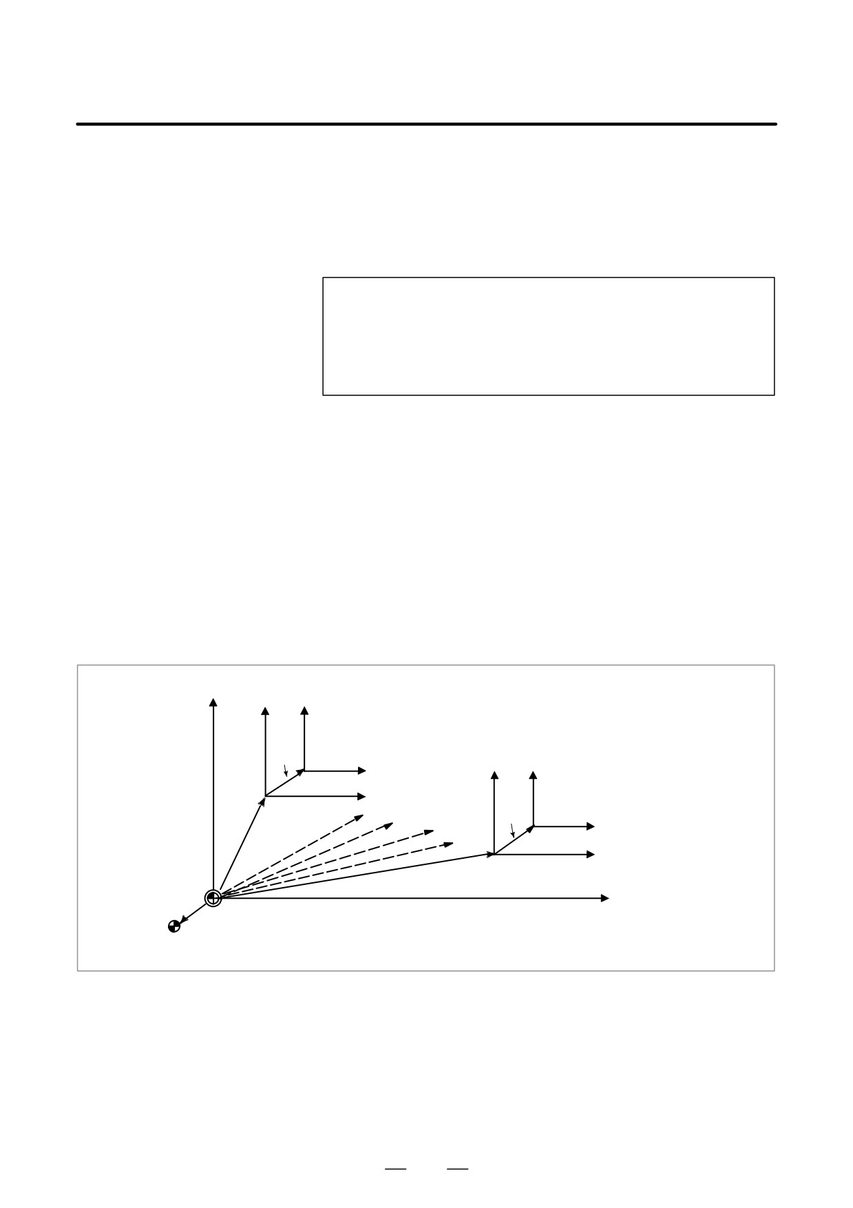
When the coordinate system actually set by the G50 command or the
automatic system setting deviates from the programmed work system, the
Workpiece Coordinate
set coordinate system can be shifted (see III-3.1).
System Shift
Set the desired shift amount in the work coordinate system shift memory.
Explanations
X
x
X-Z: Coordinate system in programming
x-z : Current set coordinate system with shift amount 0
(coordinate system to be modified by shifting)
ÎÎÎ
ÎÎÎ
ÎÎÎ
ÎÎ
O′
z
Shift
Z
O
Set the shift amount from O′ to O in the work coordinate system shift memory.
Fig. 7.2.5 Workpiece Coordinate System shift
See Section III-11.4.5 of Part III for how to specify the distance the work
coordinate system is shifted.
106
B-63524EN/01
PROGRAMMING
7. COORDINATE SYSTEM
When a program is created in a workpiece coordinate system, a child
7.3
workpiece coordinate system may be set for easier programming. Such
LOCAL COORDINATE
a child coordinate system is referred to as a local coordinate system.
SYSTEM
Format
G52 IP _; Setting the local coordinate system
G52 IP 0 ; Canceling of the local coordinate system
IP _ : Origin of the local coordinate system
Explanations
By specifying G52IP_;, a local coordinate system can be set in all the
workpiece coordinate systems (G54 to G59). The origin of each local
coordinate system is set at the position specified by IP_ in the workpiece
coordinate system.
Once a local coordinate system is established, the coordinates in the local
coordinate system are used in an axis shift command. The local
coordinate system can be changed by specifying the G52 command with
the zero point of a new local coordinate system in the workpiece
coordinate system.
To cancel the local coordinate system and specify the coordinate value in
the workpiece coordinate system, match the zero point of the local
coordinate system with that of the workpiece coordinate system.
IP_
(Local coordinate system)
(G54 : Workpiece coordinate
system 1)
G55
IP_
(Local coordinate system)
G56
G57
G58
(G59 : Workpiece coordinate system 6)
(Machine coordinate system)
Machine coordinate system origin
Reference point
Fig. 7.3 Setting the local coordinate system
107

7. COORDINATE SYSTEM
PROGRAMMING
B-63524EN/01
WARNING
1
The local coordinate system setting does not change the
workpiece and machine coordinate systems.
2
When G50 is used to define a work coordinate system, if
coordinates are not specified for all axes of a local
coordinate system, the local coordinate system remains
unchanged.
If coordinates are specified for any axis of a local coordinate
system, the local coordinate system is canceled.
3
G52 cancels the offset temporarily in tool nose radius
compensation.
4
Command a move command immediately after the G52
block in the absolute mode.
5
Whether the local coordinate system is canceled upon reset
depends on the specified parameters. The local coordinate
system is canceled upon reset when bit
6 (CLR) of
parameter No. 3402 or bit 3 (RLC) of parameter No. 1202
is set to 1.
108
B-63524EN/01
PROGRAMMING
7. COORDINATE SYSTEM
Select the planes for circular interpolation, tool nose radius
7.4
compensation, coordinate system rotation, and drilling by G-code.
PLANE SELECTION
The following table lists G-codes and the planes selected by them.
Explanations
Table 7.4 Plane selected by G code
Selected
G code
Xp
Yp
Zp
plane
G17
Xp Yp plane
X-axis or an
Y-axis or an
Z-axis or an
G18
Zp Xp plane
axis parallel
axis parallel
axis parallel
to it
to it
to it
G19
Yp Zp plane
Xp, Yp, Zp are determined by the axis address appeared in the block in
which G17, G18 or G19 is commanded.
When an axis address is omitted in G17, G18 or G19 block, it is assumed
that the addresses of basic three axes are omitted.
Parameter No. 1022 specifies whether each axis is a basic axis (X-axis,
Y-axis, or Z-axis) or an axis parallel to a basic axis.
The plane is unchanged in the block in which G17, G18 or G19 is not
commanded.
When the power is turned on, G18 (ZX plane) is selected .
The movement instruction is irrelevant to the plane selection.
NOTE
1
U-, V-, and W-axes (parallel to a basic axis) can be used
with G-codes B and C.
2
Direct drawing dimension programming, chamfering, corner
R, multiple repetitive canned cycle, and simple canned
cycle are enabled only for the ZX plane.
Specifying these functions for other planes causes P/S
alarm No. 212 to be generated.
Examples
Plane selection when the X-axis is parallel with the U-axis.
G17X_Y_; XY plane,
G17U_Y_; UY plane
G18X_Z_; ZX plane
X_Y_; Plane is unchanged (ZX plane)
G17 ;
XY plane
G18 ;
ZX plane
G17 U_ ;
UY plane
G18Y_ ;
ZX plane, Y axis moves regardless without any
relation to the plane.
109
8. COORDINATE VALUE
AND DIMENSION
PROGRAMMING
B-63524EN/01
COORDINATE VALUE AND DIMENSION
8
This chapter contains the following topics.
8.1 ABSOLUTE AND INCREMENTAL PROGRAMMING (G90, G91)
8.2 INCH/METRIC CONVERSION (G20, G21)
8.3 DECIMAL POINT PROGRAMMING
8.4 DIAMETER AND RADIUS PROGRAMMING
110
8. COORDINATE VALUE
B-63524EN/01
PROGRAMMING
AND DIMENSION
There are two ways to command travels of the tool; the absolute
8.1
command, and the incremental command. In the absolute command,
ABSOLUTE AND
coordinate value of the end position is programmed; in the incremental
INCREMENTAL
command, move distance of the position itself is programmed. G90 and
PROGRAMMING
G91 are used to command absolute or incremental command,
respectively.
(G90, G91)
Absolute programming or incremental programming is used depending
on the command used. See following tables.
G code system
A
B or C
Command method
Address word
G90, G91
Format
D G code system A
Absolute command
Incremental command
X axis move command
X
U
Z axis move command
Z
W
Y axis move command
Y
V
C axis move command
C
H
D G code system B or C
Absolute command
G90 IP_ ;
Incremental command G91 IP_ ;
Examples
D Tool movement from point
G code system A
G code system B or C
P to point Q (diameter
Absolute command
X400.0 Z50.0 ;
G90 X400.0 Z50.0 ;
programming is used for
the X-axis)
Incremental command
U200.0 W-400.0 ;
G91 X200.0 Z-400.0 ;
X
Q
(400, 50)
P
(200, 450)
φ400
φ200
Z
50
450
NOTE
1
Absolute and incremental commands can be used together
in a block.
In the above example, the following command can be
specified :
X400.0 W-400.0 ;
2
When both X and U or W and Z are used together in a block,
the one specified later is effective.
3
Incremental commands cannot be used when names of the
axes are A and B during G code system A is selected.
111
8. COORDINATE VALUE
AND DIMENSION
PROGRAMMING
B-63524EN/01
Either inch or metric input can be selected by G code.
8.2
INCH/METRIC
CONVERSION
(G20, G21)
Format
G20 ; Inch input
G21 ; mm input
This G code must be specified in an independent block before setting the
coordinate system at the beginning of the program. After the G code for
inch/metric conversion is specified, the unit of input data is switched to
the least inch or metric input increment of increment system IS-B or IS-C
(Section II-2.3). The unit of data input for degrees remains unchanged.
The unit systems for the following values are changed after inch/metric
conversion:
- Feedrate commanded by F code
- Positional command
- Work zero point offset value
- Tool compensation value
- Unit of scale for manual pulse generator
- Movement distance in incremental feed
- Some parameters
When the power is turned on, the G code is the same as that held before
the power was turned off.
WARNING
1
G20 and G21 must not be switched during a program.
2
When switching inch input (G20) to metric input (G21) and
vice versa, the tool compensation value must be re-set
according to the least input increment.
However, when bit 0 (OIM) of parameter 5006 is 1, tool
compensation values are automatically converted and
need not be re-set.
CAUTION
Movement from the intermediate point is the same as that
for manual reference position return. The direction in which
the tool moves from the intermediate point is the same as
the reference position return direction, as specified with bit
5 (ZMI) of parameter No. 1006.
NOTE
1
When the least input increment and the least command
increment systems are different, the maximum error is half
of the least command increment. This error is not
accumulated.
2
The inch and metric input can also be switched using setting
of data setting (III-11.4.7).
112
8. COORDINATE VALUE
B-63524EN/01
PROGRAMMING
AND DIMENSION
Numerical values can be entered with a decimal point. A decimal point
8.3
can be used when entering a distance, time, or speed. Decimal points can
DECIMAL POINT
be specified with the following addresses:
PROGRAMMING
X, Y, Z, U, V, W, A, B, C, I, J, K, R, and F.
Explanations
There are two types of decimal point notation: calculator-type notation
and standard notation.
When calculator-type decimal notation is used, a value without decimal
point is considered to be specified in millimeters. When standard decimal
notation is used, such a value is considered to be specified in least input
increments. Select either calculator-type or standard decimal notation by
using the DPI bit (bit 0 of parameter 3401).Values can be specified both
with and without decimal point in a single program.
Examples
Pocket calculator
Standard type decimal
Program command
type decimal point
point programming
programming
X1000
1000mm
1mm
Command value with-
Unit : mm
Unit : Least input increment
out decimal point
(0.001 mm)
X1000.0
1000mm
1000mm
Command value with
Unit : mm
Unit : mm
decimal point
WARNING
In a single block, specify a G code before entering a value. The position of decimal point may
depend on the command.
Examples:
G20; Input in inches
X1.0 G04; X1.0 is considered to be a distance and processed as X10000. This command
is equivalent to G04 X10000. The tool dwells for 10 seconds.
G04 X1.0; Equivalent to G04 X1000. The tool dwells for one second.
NOTE
1
Fractions less than the least input increment are truncated.
Examples:
X1.23456;
Truncated to X1.234 when the least input increment is 0.001 mm.
Processed as X1.2345 when the least input increment is 0.0001 inch.
2
When more than eight digits are specified, an alarm occurs. If a value is entered with a decimal
point, the number of digits is also checked after the value is converted to an integer according
to the least input increment.
Examples:
X1.23456789; P/S alarm 003 occurs because more than eight digits are specified.
X123456.7; If the least input increment is 0.001 mm, the value is converted to integer
123456700. Because the integer has more than eight digits, an P/S alarm 003
occurs.
113
8. COORDINATE VALUE
AND DIMENSION
PROGRAMMING
B-63524EN/01
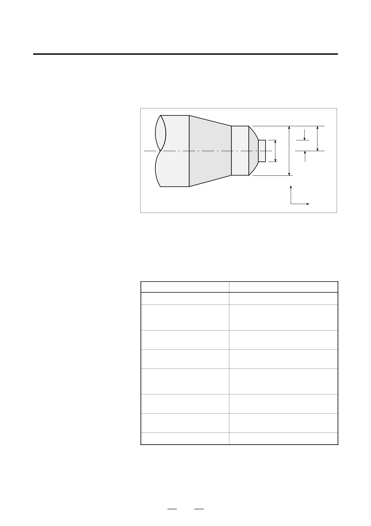
Since the work cross section is usually circular in CNC lathe control
8.4
programming, its dimensions can be specified in two ways :
DIAMETER AND
Diameter and Radius
RADIUS
When the diameter is specified, it is called diameter programming and
PROGRAMMING
when the radius is specified, it is called radius programming.
A
B
R2
R1
D1
D2
X axis
D1, D2 : Diameter programming
R1, R2
: Radius programming
Z axis
Explanations
D Notes on diameter
Radius programming or diameter programming can be specified by
programming/radius
parameter DIA (No.1006#3). When using diameter programming, note
programming for each
the conditions listed in the table 8.4.
command
Table 8.4 Notes on specifying diameter value
Item
Notes
X axis command
Specified with a diameter value
Incremental command
Specified with a diameter value
In the above figure, specifies D2 minus
D1 for tool path B to A.
Coordinate system setting (G50)
Specifies a coordinate value with a diam-
eter value
Component of tool offset value
Parameter (No.5004#1) determines either
diameter or radius value
Parameters in canned cycle,
Specifies a radius value
such as cutting depth along X
axis. (R)
Radius designation in circular in-
Specifies a radius value
terpolation (R, I, K, and etc.)
Feedrate along axis
Specifies change of radius/rev. or change
of radius/min.
Display of axis position
Displayed as diameter value
114
B-63524EN/01
PROGRAMMING
9. SPINDLE SPEED FUNCTION
SPINDLE SPEED FUNCTION
9
The spindle speed can be controlled by specifying a value following
address S.
In addition, the spindle can be rotated by a specified angle.
This chapter contains the following topics.
9.1 SPECIFYING THE SPINDLE SPEED WITH A CODE
9.2 SPECIFYING THE SPINDLE SPEED VALUE DIRECTLY
(S5-DIGIT COMMAND)
9.3 CONSTANT SURFACE SPEED CONTROL (G96, G97)
9.4 SPINDLE SPEED FLUCTUATION DETECTION FUNCTION
(G25, G26)
9.5 SPINDLE POSITIONING FUNCTION
115

9. SPINDLE SPEED FUNCTION
PROGRAMMING
B-63524EN/01
Specifying a value following address S sends code and strobe signals to
9.1
the machine. On the machine, the signals are used to control the spindle
SPECIFYING THE
speed. A block can contain only one S code. Refer to the appropriate
SPINDLE SPEED
manual provided by the machine tool builder for details such as the
WITH A CODE
number of digits in an S code or the execution order when a move
command and an S code command are in the same block.
The spindle speed can be specified directly by address S followed by a
9.2
five-digit value (min-1). The unit for specifying the spindle speed may
SPECIFYING THE
vary depending on the machine tool builder. Refer to the appropriate
SPINDLE SPEED
manual provided by the machine tool builder for details.
VALUE DIRECTLY
(S5-DIGIT
COMMAND)
Specify the surface speed (relative speed between the tool and workpiece)
9.3
following S. The spindle is rotated so that the surface speed is constant
CONSTANT
regardless of the position of the tool.
SURFACE SPEED
CONTROL
(G96, G97)
Format
D Constant surface speed
control command
G96 Sfffff ;
↑Surface speed (m/min or feet/min)
Note : This surface speed unit may change according to
machine tool builder’s specification.
D Constant surface speed
control cancel command
G97 Sfffff ;
↑Spindle speed (min-1)
Note : This surface speed unit may change according to
machine tool builder’s specification.
D Clamp of maximum
spindle speed
G50 S_ ;
The maximum spindle speed (min-1) follows S.
116
B-63524EN/01
PROGRAMMING
9. SPINDLE SPEED FUNCTION
Explanations
D Constant surface speed
G96 (constant surface speed control command) is a modal G code. After
control command (G96)
a G96 command is specified, the program enters the constant surface
speed control mode (G96 mode) and specified S values are assumed as a
surface speed. A G96 command must specify the axis along which
constant surface speed control is applied. A G97 command cancels the
G96 mode.When constant surface speed control is applied, a spindle
speed higher than the value specified in G50S_; (maximum spindle
speed) is clamped at the maximum spindle speed. When the power is
turned on, the maximum spindle speed is not yet set and the speed is not
clamped.S (surface speed) commands in the G96 mode are assumed as S
= 0 (the surface speed is 0) until M03 (rotating the spindle in the positive
direction) or M04 (rotating the spindle in the negative direction) appears
in the program.
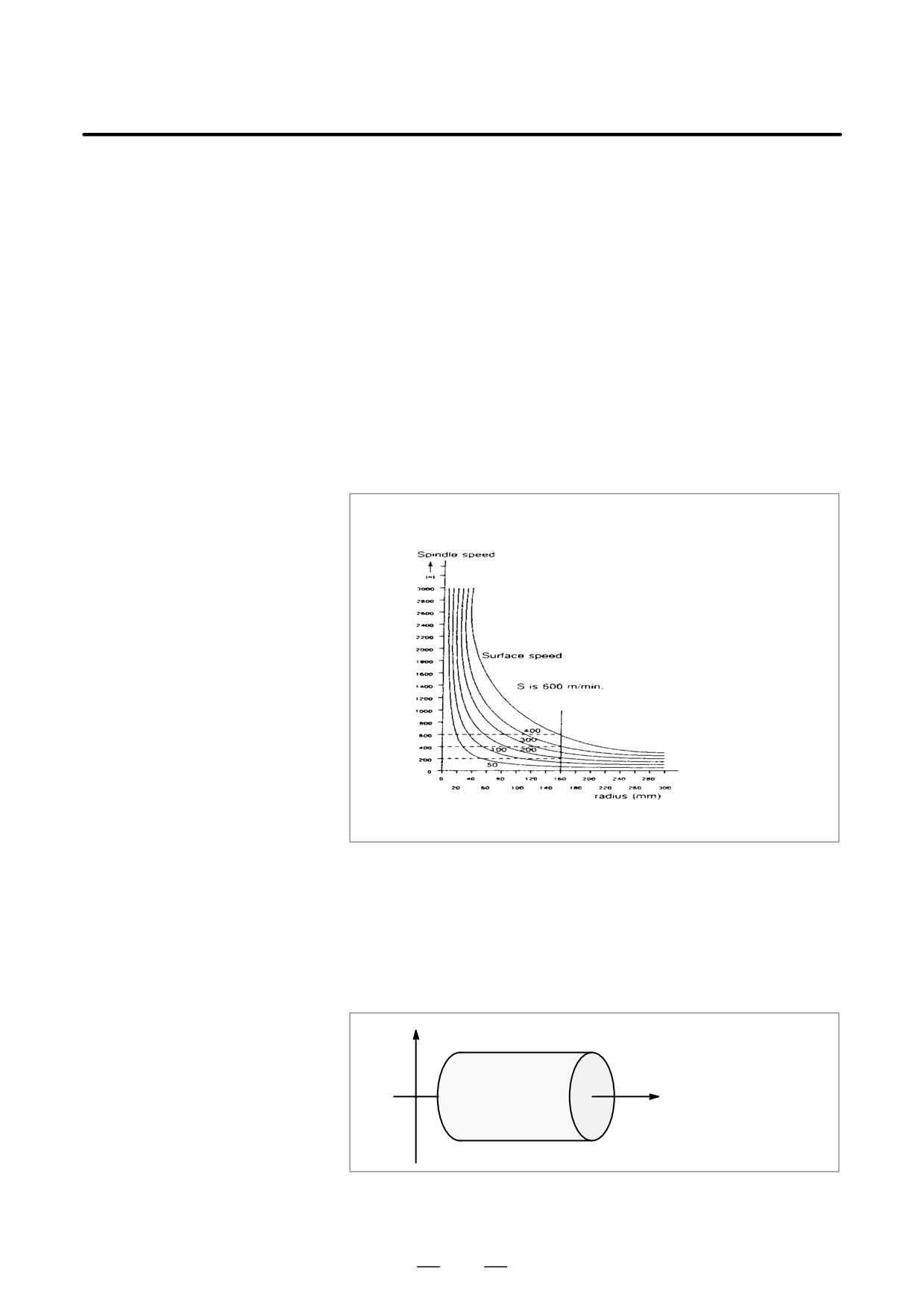
The spindle speed (min-1) almost
(min-1)
coincides with the surface speed
(m/min) at approx. 160 mm (radius).
Fig. 9.3 (a) Relation between workpiece radius, spindle speed
and surface speed
D Setting the workpiece
To execute the constant surface speed control, it is necessary to set the
coordinate system for
work coordinate system , Z axis, (axis to which the constant surface speed
constant surface speed
control applies) becomes zero.
control
X
Z
0
Fig. 9.3 (b) Example of the Workpiece Coordinate
System for Constant Surface Speed Control
117
9. SPINDLE SPEED FUNCTION
PROGRAMMING
B-63524EN/01
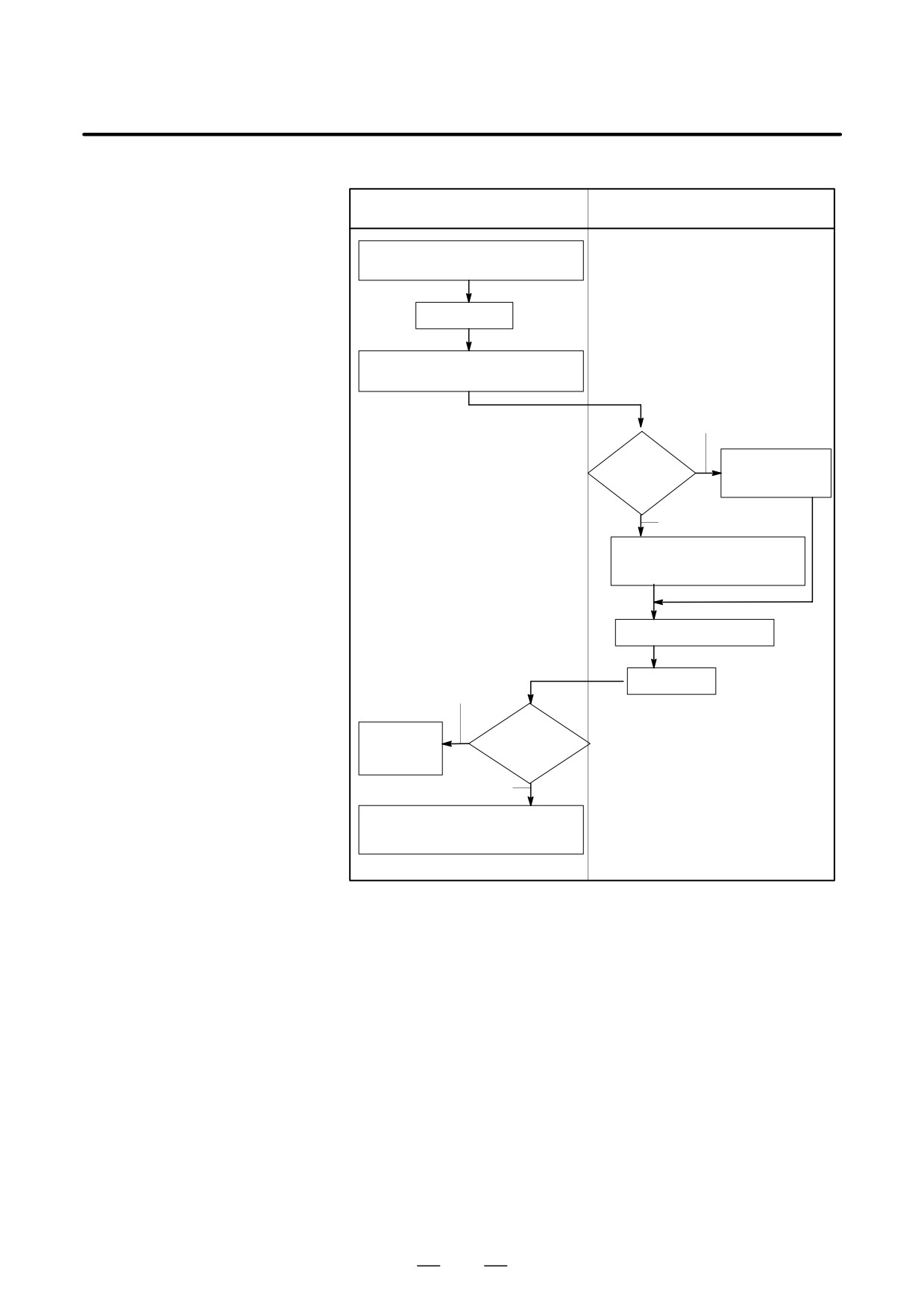
D Surface speed specified
in the G96 mode
G96 mode
G97 mode
Specify the surface speed in m/min
(or feet/min)
G97 command
Store the surface speed in m/min
(or feet/min)
Specified
Command for
The specified
the spindle
spindle speed
speed
(min-1) is used
Not specified
The surface speed (m/min or
feet/min) is converted to the
spindle speed (min-1)
Commands other than G96
G96 command
Specified
The specified
Command
surface
for the surface
speed is used
speed
Not specified
The stored surface speed (m/min or
feet/min) is used. If no surface speed is
stored, 0 is assumed.
Restrictions
D Constant surface speed
The constant surface speed control is also effective during threading.
control for threading
Accordingly, it is recommended that the constant surface speed control
be invalidated with G97 command before starting the scroll threading and
taper threading, because the response problem in the servo system may
not be considered when the spindle speed changes.
118
B-63524EN/01
PROGRAMMING
9. SPINDLE SPEED FUNCTION
D Constant surface speed
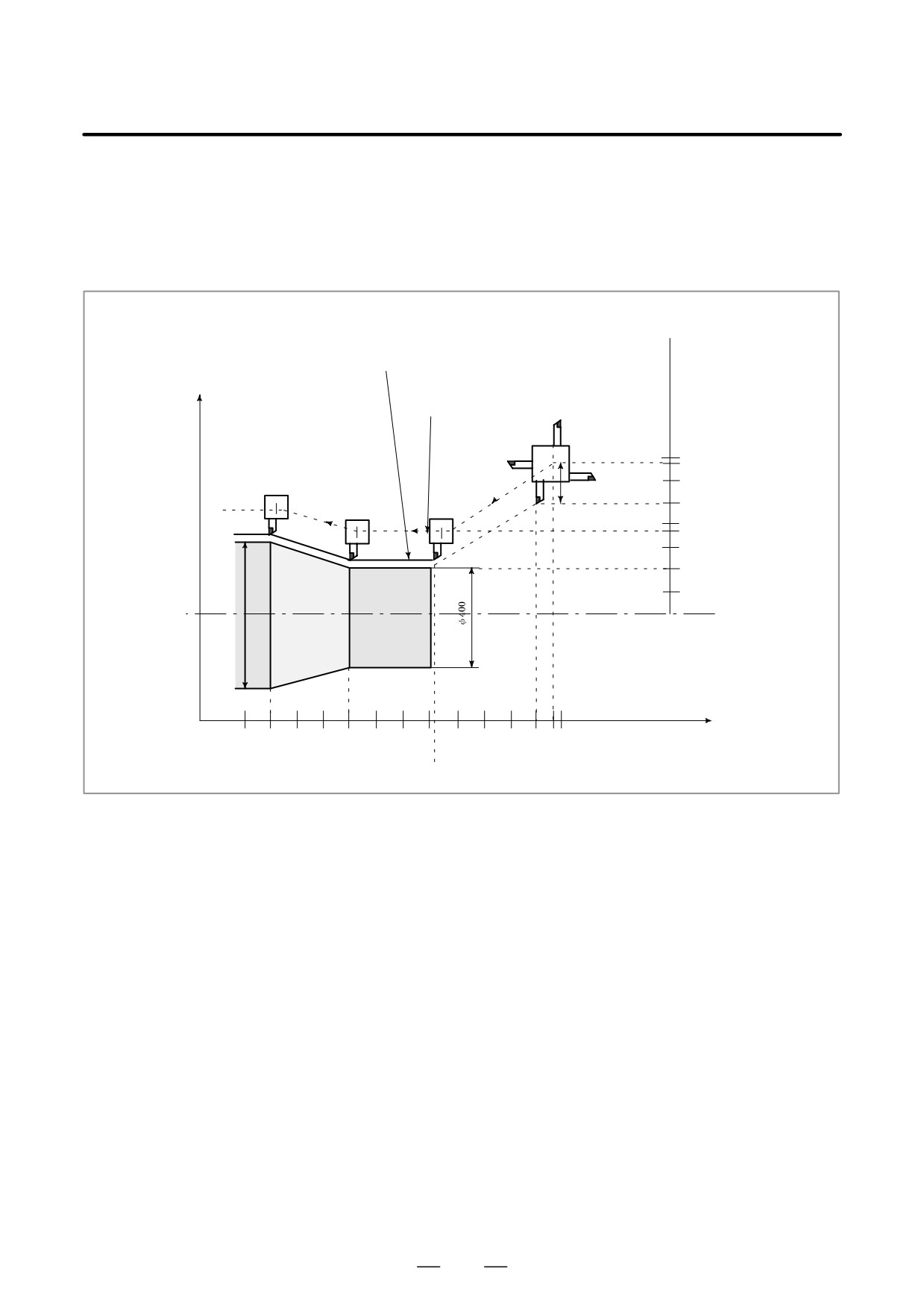
In a rapid traverse block specified by G00, the constant surface speed
control for rapid traverse
control is not made by calculating the surface speed to a transient change
(G00)
of the tool position, but is made by calculating the surface speed based on
the position at the end point of the rapid traverse block, on the condition
that cutting is not executed at rapid traverse.
Radius value
Programmed path
X
Tool path after offset
1
2
700
4
675
600
N11
N16
3
N15
500
N11
N14
400
N16
N15
375
N14
300
200
100
φ600
Z
300
400
500
600
700
800
900
1000
1100 1200
1300 1400
1500
1475
1050
Example
N8 G00 X1000.0Z1400.0 ;
N9 T33;
N11 X400.0Z1050.0;
N12 G50S3000 ; (Designation of max. spindle speed)
N13 G96S200 ; (Surface speed 200 m/min)
N14 G01 Z 700.0F1000 ;
N15 X600.0Z 400.0;
N16 Z … ;
The CNC calculates the spindle speed which is proportional to the
specified surface speed at the position of the programmed coordinate
value on the X axis. This is not the value calculated according to the X
axis coordinate after offset when offset is valid. At the end point N15 in
the example above, the speed at 600 dia. (Which is not the turret center
but the tool nose) is 200 m/min. If X axis coordinate value is negative,
the CNC uses the absolute value.
119
9. SPINDLE SPEED FUNCTION
PROGRAMMING
B-63524EN/01
With this function, an overheat alarm (No. 704) is raised when the spindle
9.4
speed deviates from the specified speed due to machine conditions.
SPINDLE SPEED
This function is useful, for example, for preventing the seizure of the
FLUCTUATION
guide bushing.
DETECTION
FUNCTION
(G25, G26)
Format
G26 enables spindle speed fluctuation detection.
G25 disables spindle speed fluctuation detection.
G26 Pp Qq Rr ;
Spindle fluctuation detection on
G25 ;
Spindle fluctuation detection off
p : Time (in ms) from the issue of a new spindle rotation command (S
command) to the start of checking whether the actual spindle speed is
so fast that an overheat can occur.
When a specified speed is reached within the time period of P, spindle
speed is checked at that time.
q : Tolerance (%) of a specified spindle speed
1-actual spindle speed
q+
100
specified spindle speed
If a specified spindle speed lies within this range, it is regarded as
having reached the specified value. Then, an actual spindle speed is
checked.
r : Spindle speed fluctuation (%) at which the actual spindle speed is so
fast that an overheat can occur
1-speed that can cause overheat
r+
100
specified spindle speed
G26 enables the spindle speed fluctuation detection function, and G25
disables the spindle speed fluctuation detection.
Even if G25 is specified, p, q, and r are not cleared.
120
B-63524EN/01
PROGRAMMING
9. SPINDLE SPEED FUNCTION
Explanations
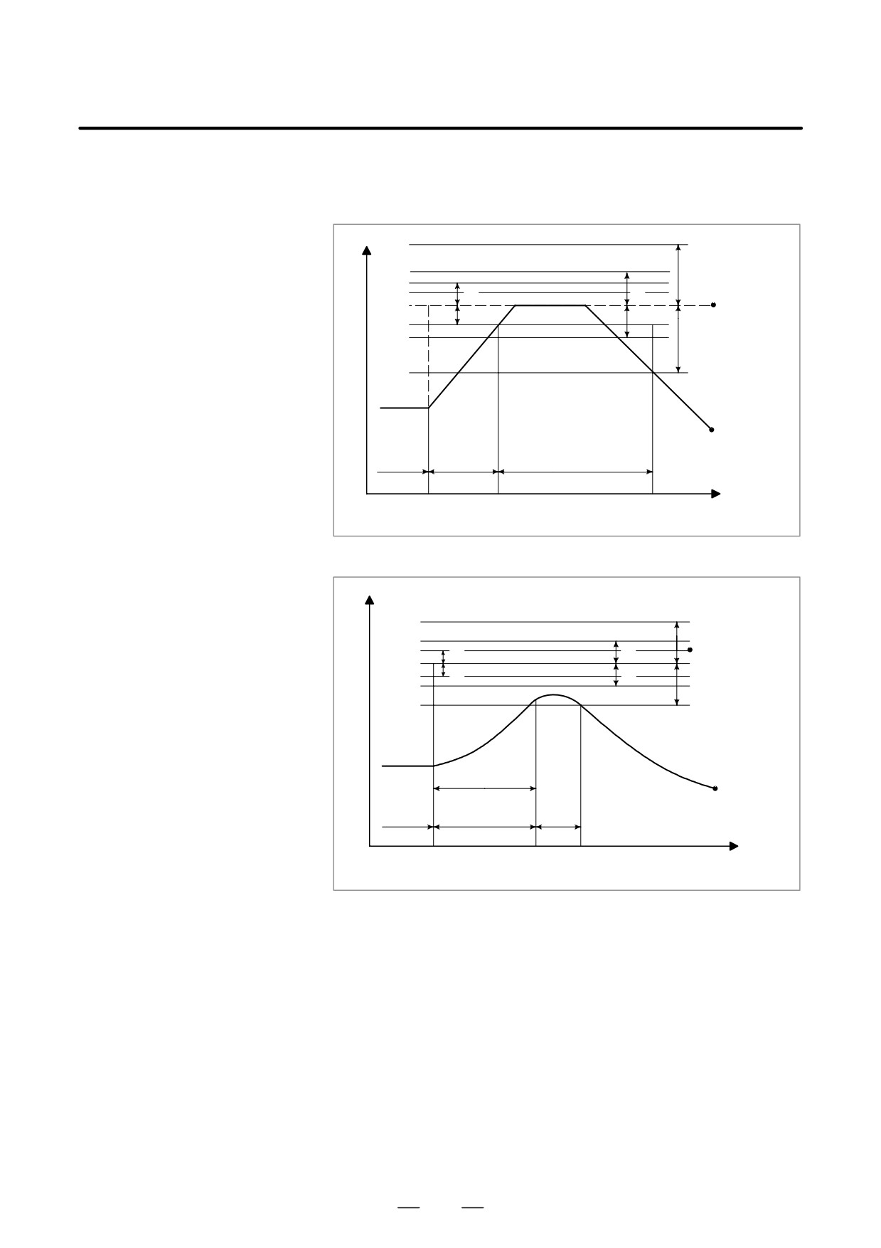
The fluctuation of the spindle speed is detected as follows:
1. When an alarm is issued after a specified spindle speed is reached
Spindle speed
r
d
q
Specified
q
d
speed
r
Actual speed
Check
No
check
Check
Time
Specification of Start of check
Alarm
another speed
2. When an alarm is issued before a specified spindle speed is reached
Spindle speed
r
q
d
Specified
speed
q
d
r
Actual speed
p
Check
No check
Check
Time
Specification of
Start of check
Alarm
another speed
Specified speed :
(Speed specified by address S and five-digit value)
(spindle
override)
Actual speed : Speed detected with a position coder
p : Time elapses since the specified speed changes until a check starts.
q : (Percentage tolerance for a check to start)
(specified speed)
r :
(Percentage fluctuation detected as an alarm condition)
(specified
speed)
d : Fluctuation detected as an alarm (specified in parameter 4913)
An alarm is issued when the difference between the specified speed and
the actual speed exceeds both r and d.
121

9. SPINDLE SPEED FUNCTION
PROGRAMMING
B-63524EN/01
NOTE
1
When an alarm is issued in automatic operation, a single
block stop occurs. The spindle overheat alarm is indicated
on the CRT screen, and the alarm signal “SPAL” is output
(set to 1 for the presence of an alarm). This signal is cleared
by resetting.
2
Even when reset operation is performed after an alarm
occurs, the alarm is issued again unless the cause of the
alarm is corrected.
3
No check is made during spindle stop state (*SSTP = 0).
4
By setting the parameter (No. 4913), an allowable range of
speed fluctuations can be set which suppresses the
occurrence of an alarm. However, an alarm is issued one
second later if the actual speed is found to be 0 min-1.
122
B-63524EN/01
PROGRAMMING
9. SPINDLE SPEED FUNCTION
In turning, the spindle connected to the spindle motor is rotated at a certain
9.5
speed to rotate the workpiece mounted on the spindle. The spindle
SPINDLE
positioning function turns the spindle connected to the spindle motor by
POSITIONING
a certain angle to position the workpiece mounted on the spindle at a
FUNCTION
certain angle. The spindle is positioned about the C-axis.
The spindle positioning function involves the following three operations:
1. Canceling the spindle rotation mode and entering the spindle
positioning mode (spindle orientation)
2. Positioning the spindle in the spindle positioning mode
3. Canceling the spindle positioning mode, and entering the spindle
rotation mode
9.5.1
When spindle positioning is first performed after the spindle motor is used
for normal spindle operation, or when spindle positioning is interrupted,
Spindle Orientation
the spindle orientation is required.
Orientation permits the spindle to stop at a predetermined position.
Orientation is directed by the M code set in parameter No. 4960. The
direction of orientation can be set with a parameter. For the analog
spindle, the direction is set in ZMIx (bit 5 of parameter 1006).
For the serial spindle, it is set in RETRN (bit 5 of parameter 4005).
9.5.2
The spindle can be positioned with an arbitrary angle or semi-fixed angle.
Spindle Positioning
D Positioning with a
Address M is followed by a 2-digit numeric. The specifiable value may
semi-fixed angle
be one of the six values from Mα to M (α+5). Value α must be set in
specified by an M code
parameter No. 4962 beforehand. The positioning angles corresponding
to Mα to M (α+5) are listed below. Value β must be set in parameter No.
4963 beforehand.
M-code
Positioning angle
(Ex.)β=30°
Mα
β
30°
M(α+1)
2β
60°
M(α+2)
3β
90°
M(α+3)
4β
120°
M(α+4)
5β
150°
M(α+5)
6β
180°
Specify the command with incremental values. The direction of rotation
can be specified in parameter IDM (bit 1 of parameter 4950).
123
9. SPINDLE SPEED FUNCTION
PROGRAMMING
B-63524EN/01
D Positioning with a given
Specify the position using address C or H followed by a signed numeric
angle specified by
value or numeric values. Addresses C and H must be specified in the G00
address C or H
mode.
(Example) C-1000
H4500
The end point must be specified with a distance from the program
reference position (in absolute mode) using address C. Alternatively, the
end point must also be specified with a distance from the start point to the
end point (in incremental mode) using address H.
A numeric with the decimal point can be entered.
The value must be specified in degrees.
(Example) C35.0=C35 degrees
D Program reference
The position to which the spindle is oriented is assumed as the program
position
reference position. The program reference position can be changed by
setting of a coordinate system (G50) or automatic setting of a coordinate
system (#OZPR of parameter 1202).
D Feedrate for positioning
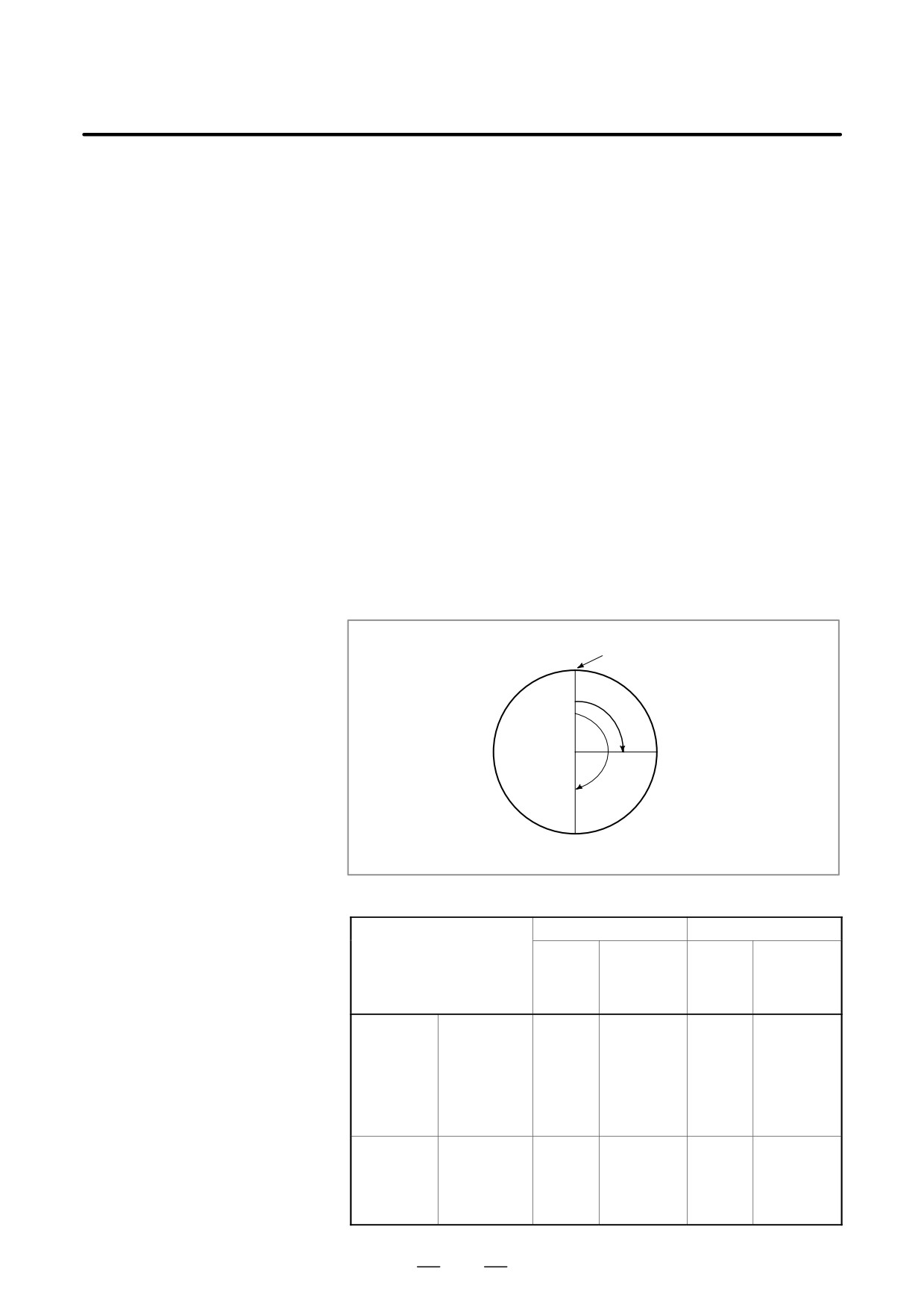
Program reference
position
90°
A
180°
B
G code A
G code B and C
Command
Addres
Command
Command format
Addres
A-B in the
s used
A-B in the
s used
above
and G
above
figure
code
figure
Specify the
end point
with a dis-
Absolute
tance from
C
C180.0 ;
G90,C
G90C180.;
command
the program
reference
position.
Specify a dis-
tance from
Incremental
the start
H
H90.0 ;
G91,C
G90C90. ;
command
point to the
end point.
124

B-63524EN/01
PROGRAMMING
9. SPINDLE SPEED FUNCTION
D Feedrate during
The feedrate during positioning equals the rapid traverse speed specified
positioning
in parameter No. 1420. Linear acceleration/deceleration is performed.
For the specified speed, an override of 100%, 50%, 25%, and F0
(parameter No. 1421) can be applied.
D Speed during orientation
The tool moves at the rapid traverse speed set in parameter No.1420 until
a sufficient speed for orientation is attained. After the speed for
orientation has been attained, orientation is performed at the speed set in
parameter No. 1425.
9.5.3
When modes are to be switched from spindle positioning to normal
spindle rotation, the M code set in parameter No. 4961 is specified.
Canceling Spindle
Positioning
WARNING
1
Feed hold, dry run, machine lock, and auxiliary function lock
cannot be performed during spindle positioning.
2
Parameter No.
4962 must always be set even when
positioning with a semi-fixed angle specified in an M-code
is not performed. If the parameter is not set, M-codes from
the M00 to M05 do not function properly.
NOTE
1
Specify spindle positioning alone in a block. A move
command for the X or Z axis cannot be specified within the
same block.
2
When emergency stop is applied during spindle positioning,
spindle positioning stops. To resume it, restart with the
orientation step.
3
The serial spindle Cs-axis contour control function and the
spindle positioning function cannot be used at a time. If both
options are specified, the spindle positioning function has
priority.
4
The spindle positioning axis is indicated in pulses in the
machine coordinate system.
125
10. TOOL FUNCTION (T FUNCTION)
PROGRAMMING
B-63524EN/01
TOOL FUNCTION (T FUNCTION)
10
Two tool functions are available. One is the tool selection function, and
the other is the tool life management function.
126
B-63524EN/01
PROGRAMMING
10. TOOL FUNCTION (T FUNCTION)
By specifying a 2-digit/4-digit numerical value following address T, a
10.1
code signal and a strobe signal are transmitted to the machine tool. This
TOOL SELECTION
is mainly used to select tools on the machine.
One T code can be commanded in a block. Refer to the machine tool
builder’s manual for the number of digits commandable with address T
and the correspondence between the T codes and machine operations.
When a move command and a T code are specified in the same block, the
commands are executed in one of the following two ways:
1. Simultaneous execution of the move command and T function
commands.
2. Executing T function commands upon completion of move command
execution.
The selection of either sequence depends on the machine tool builder’s
specifications. Refer to the machine tool builder’s manual for details.
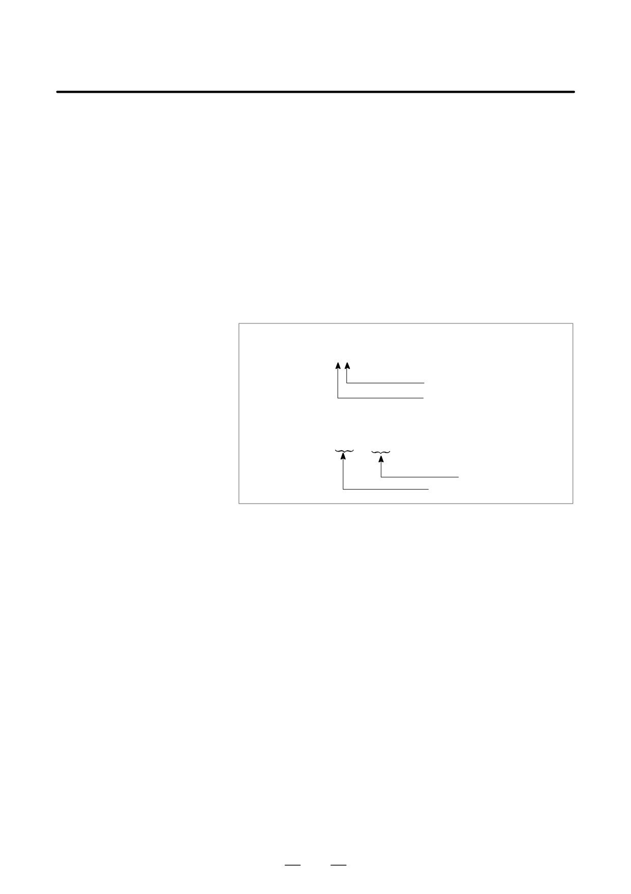
1. Last one digit of T-code designates the offset number.
T ff
Tool offset number
Tool selection
2. Last two digits of T-code designate the offset number.
T ff
ff
Tool offset number
Tool selection
Explanations
The value after the T code indicates the desired tool. Part of the values
is also used as the offset number indicating the compensation amount for
tool offset.
Refer to the machine tool builder’s manual for correspondence between
the T-code and the tool and the number of digit to specify tool selection.
Example (T2+2)
N1G00X1000Z1400
N2T0313; (Select Tool No. 3 and Offset value No. 13)
N3X400Z1050;
Some machines use a 1-digit value to specify tool selection.
127
10. TOOL FUNCTION (T FUNCTION)
PROGRAMMING
B-63524EN/01
Tools are classified into some groups. For each group, a tool life (time
10.2
or frequency of use) is specified. Each time a tool is used, the time for
TOOL LIFE
which the tool is used is accumulated. When the tool life has been
MANAGEMENT
reached, the next tool previously determined in the same group is used.
This function is called the tool life management function.
With 2-path control, tool life management is performed for each tool post
separately. So tool life management data is also set for each tool post.
10.2.1
Program of Tool Life
Data
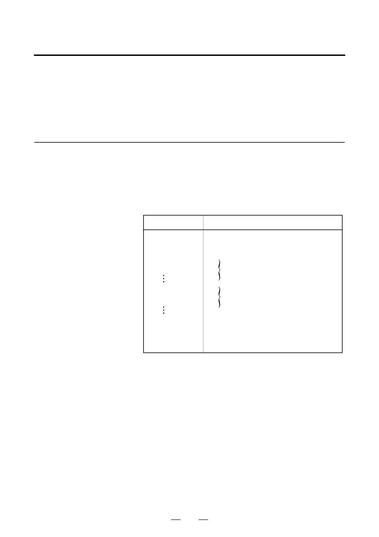
Format
Tools used sequentially in each group and their tool life are registered in
the CNC as following program format of table 10.2.1 (a).
Table 10.2.1 (a) Program format of life management
Tape format
Meaning
O_ _ _ _
;
Program number
G10L3;
Start of setting tool life data
P_ _ _ L_ _ _ _
;
P___ :Group number (1 to 128)
L___ :Tool life (1 to 9999)
T_ _ _ _
;
(1)
T:____ Tool number
T_ _ _ _
;
(2)
Tools are selected from
(n)
(1)to (2) to ... to (n).
P_ _ _ L_ _ _ _ ;
T_ _ _ _
;
Data for the next group
T_ _ _ _
;
G11;
End of setting tool life data
M02(M30);
End of program
For the method of registering tool life data in CNC, refer to Subsec.
III-11.4.14.
128