FANUC Series Series 16i-TB, Series 18i-TB, Series 160i-TB, Series 180i-TB. OPERATOR’S MANUAL - page 4
B-63524EN/01
PROGRAMMING
4. INTERPOLATION FUNCTIONS
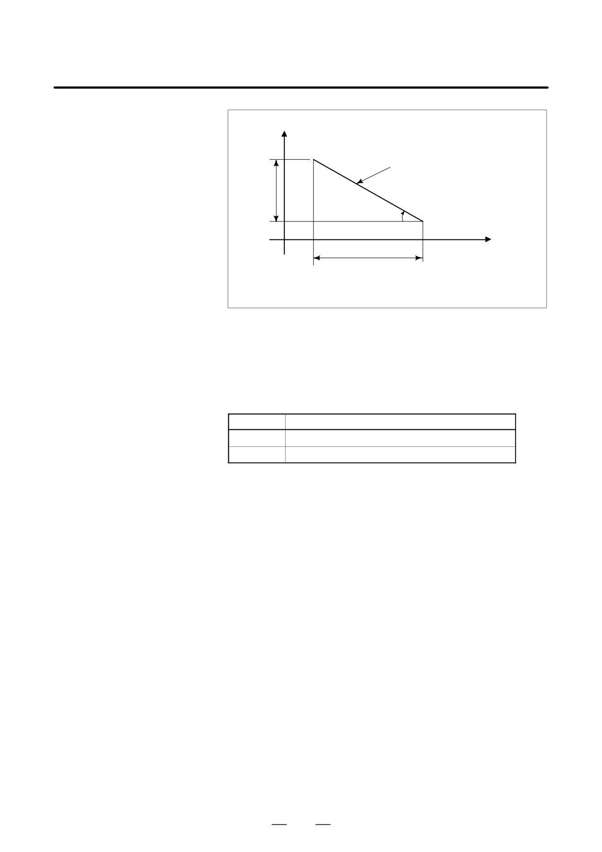
X
Tapered thread
LX
α
Z
LZ
αx45° lead is LZ
αy45° lead is LX
Fig. 4.9 (e) LZ and LX of a Tapered Thread
In general, the lag of the servo system, etc. will produce somewhat
incorrect leads at the starting and ending points of a thread cut. To
compensate for this, a threading length somewhat longer than required
should be specified.
Table 4.9 lists the ranges for specifying the thread lead.
Table. 4.9 Ranges of lead sizes that can be specified
Least command increment
mm input
0.0001 to 500.0000mm
Inch input
0.000001 inch to 9.999999inch
69
4. INTERPOLATION FUNCTIONS
PROGRAMMING
B-63524EN/01
Explanations
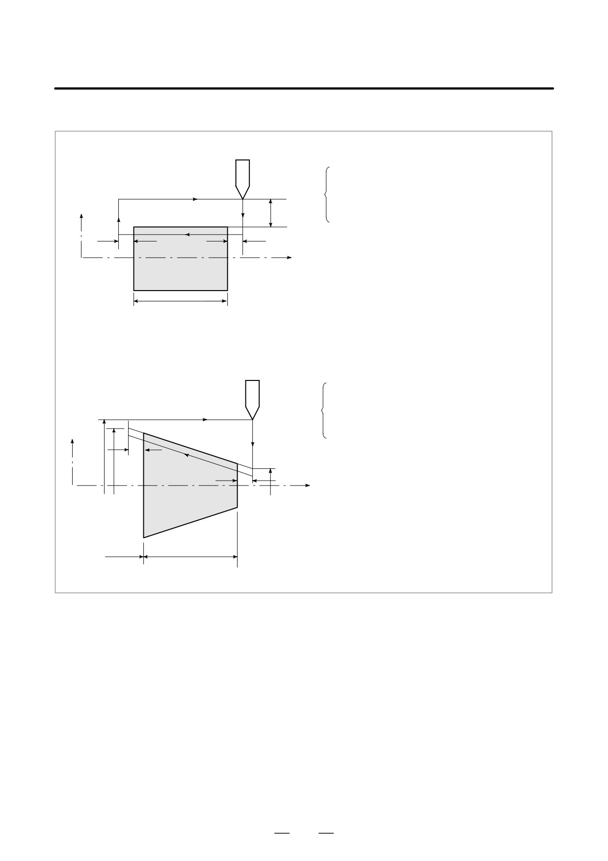
1. Straight thread cutting
The following values are used in programming :
Thread lead :4mm
δ1=3mm
δ2=1.5mm
X axis
30mm
Depth of cut :1mm (cut twice)
(Metric input, Diameter programming)
δ2
δ1
G00
U-62.0 ;
G32
W-74.5 F4.0 ;
Z axis
G00
U62.0 ;
W74.5 ;
U-64.0 ;
(For the second cut, cut 1mm more)
70
G32 W-74.5 ;
G00
U64.0 ;
W74.5 ;
2. Tapered thread cutting
The following values are used in programming :
Thread lead : 3.5mm in the direction of the Z axis
δ1=2mm
δ2=1mm
X axis
Cutting depth in the X axis direction is 1mm
(Cut twice)
φ50
δ2
(Metric input, Diameter programming)
φ43
G00
X 12.0 Z72.0 ;
δ1
G32
X 41.0 Z29.0 F3.5 ;
G00
X 50.0 ;
0
Z axis
Z 72.0 ;
φ14
X 10.0 ;
(Cut 1mm more for the second cut)
G32 X 39.0 Z29.0 ;
G00
X 50.0 ;
30
40
Z 72.0 ;
70
B-63524EN/01
PROGRAMMING
4. INTERPOLATION FUNCTIONS
WARNING
1
Feedrate override is effective (fixed at 100%) during thread cutting.
2
It is very dangerous to stop feeding the thread cutter without stopping the spindle. This will
suddenly increase the cutting depth. Thus, the feed hold function is ineffective while thread
cutting. If the feed hold button is pressed during thread cutting, the tool will stop after a block
not specifying thread cutting is executed as if the SINGLE BLOCK button were pushed.
However, the feed hold lamp (SPL lamp) lights when the FEED HOLD button on the machine
control panel is pushed. Then, when the tool stops, the lamp is turned off (Single Block stop
status).
3
When the FEED HOLD button is held down, or is pressed again in the first block that does not
specify thread cutting immediately after a thread cutting block, the tool stops at the block that
does not specify thread cutting.
4
When thread cutting is executed in the single block status, the tool stops after execution of the
first block not specifying thread cutting.
5
When the mode was changed from automatic operation to manual operation during thread
cutting, the tool stops at the first block not specifying thread cutting as when the feed hold button
is pushed as mentioned in Note 3.
However, when the mode is changed from one automatic operation mode to another, the tool
stops after execution of the block not specifying thread cutting as for the single block mode in
Note 4.
6
When the previous block was a thread cutting block, cutting will start immediately without
waiting for detection of the 1-turn signal even if the present block is a thread cutting block.
G32Z _ F_ ;
Z _;
(A 1-turn signal is not detected before this block.)
G32 ;
(Regarded as threading block.)
Z_ F_ ;(One turn signal is also not detected.)
7
Because the constant surface speed control is effective during scroll thread or tapered screw
cutting and the spindle speed changes, the correct thread lead may not be cut. Therefore, do
not use the constant surface speed control during thread cutting. Instead, use G97.
8
A movement block preceding the thread cutting block must not specify chamfering or corner
R.
9
A thread cutting block must not specifying chamfering or corner R.
10 The spindle speed override function is disabled during thread cutting. The spindle speed is
fixed at 100%.
11 Thread cycle retract function is ineffective to G32.
71
4. INTERPOLATION FUNCTIONS
PROGRAMMING
B-63524EN/01
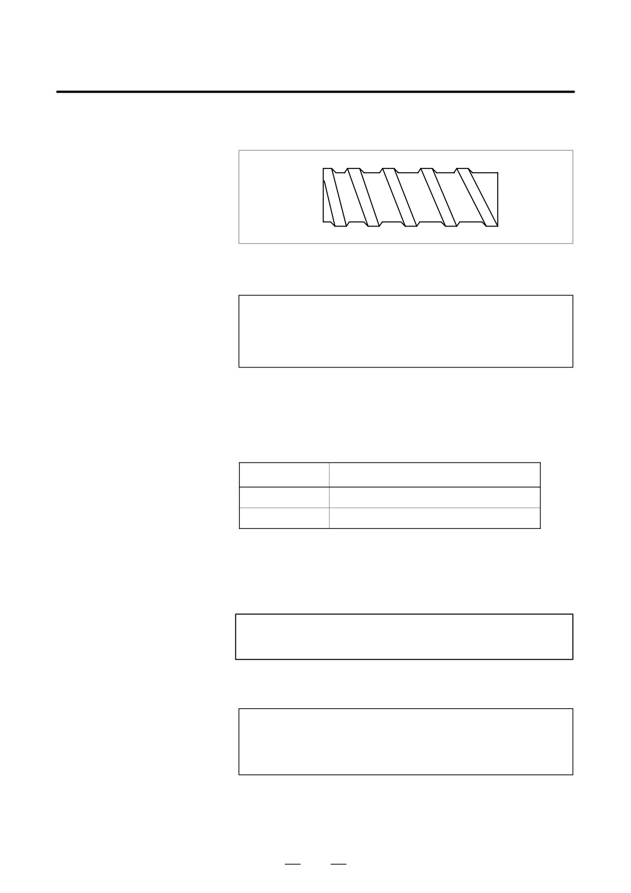
Specifying an increment or a decrement value for a lead per screw
4.10
revolution enables variable-lead thread cutting to be performed.
VARIABLE-LEAD
THREAD CUTTING
(G34)
Fig. 4.10 Variable-lead screw
Format
G34 IP_F_K_;
IP : End point
F : Lead in longitudinal axis direction at the start point
K : Increment and decrement of lead per spindle revolution
Explanations
Address other than K are the same as in straight/taper thread cutting with
G32.
Table 4.10 lists a range of values that can be specified as K.
Table 4.10 Range of valid K values
Metric input
0.0001 to
500.0000 mm/rev
Inch input
0.000001 to
9.999999 inch/rev
P/S alarm (No. 14) is produced, for example, when K such that the value
in Table 4.10 is exceeded is directed, the maximum value of lead is
exceeded as a result of increase or decrease by K or the lead has a negative
value.
WARNING
The “Thread Cutting Cycle Retract” is not effective for G34.
Examples
Lead at the start point: 8.0 mm
Lead increment: 0.3 mm/rev
G34 Z-72.0 F8.0 K0.3 ;
72

B-63524EN/01
PROGRAMMING
4. INTERPOLATION FUNCTIONS
This function for continuous thread cutting is such that fractional pulses
4.11
output to a joint between move blocks are overlapped with the next move
CONTINUOUS
for pulse processing and output (block overlap) .
THREAD CUTTING
Therefore, discontinuous machining sections caused by the interruption
of move during continuously block machining are eliminated, thus
making it possible to continuously direct the block for thread cutting
instructions.
Explanations
Since the system is controlled in such a manner that the synchronism
with the spindle does not deviate in the joint between blocks wherever
possible, it is possible to performed special thread cutting operation in
which the lead and shape change midway.
G32
G32
G32
Fig. 4.11 Continuous Thread Cutting
Even when the same section is repeated for thread cutting while changing
the depth of cut, this system allows a correct machining without impairing
the threads.
NOTE
1
Block overlap is effective even for G01 command,
producing a more excellent finishing surface.
2
When extreme micro blocks continue, no block overlap may
function.
73
4. INTERPOLATION FUNCTIONS
PROGRAMMING
B-63524EN/01
Using the Q address to specify an angle between the one-spindle-rotation
4.12
signal and the start of threading shifts the threading start angle, making
MULTIPLE-THREAD
it possible to produce multiple-thread screws with ease.
CUTTING
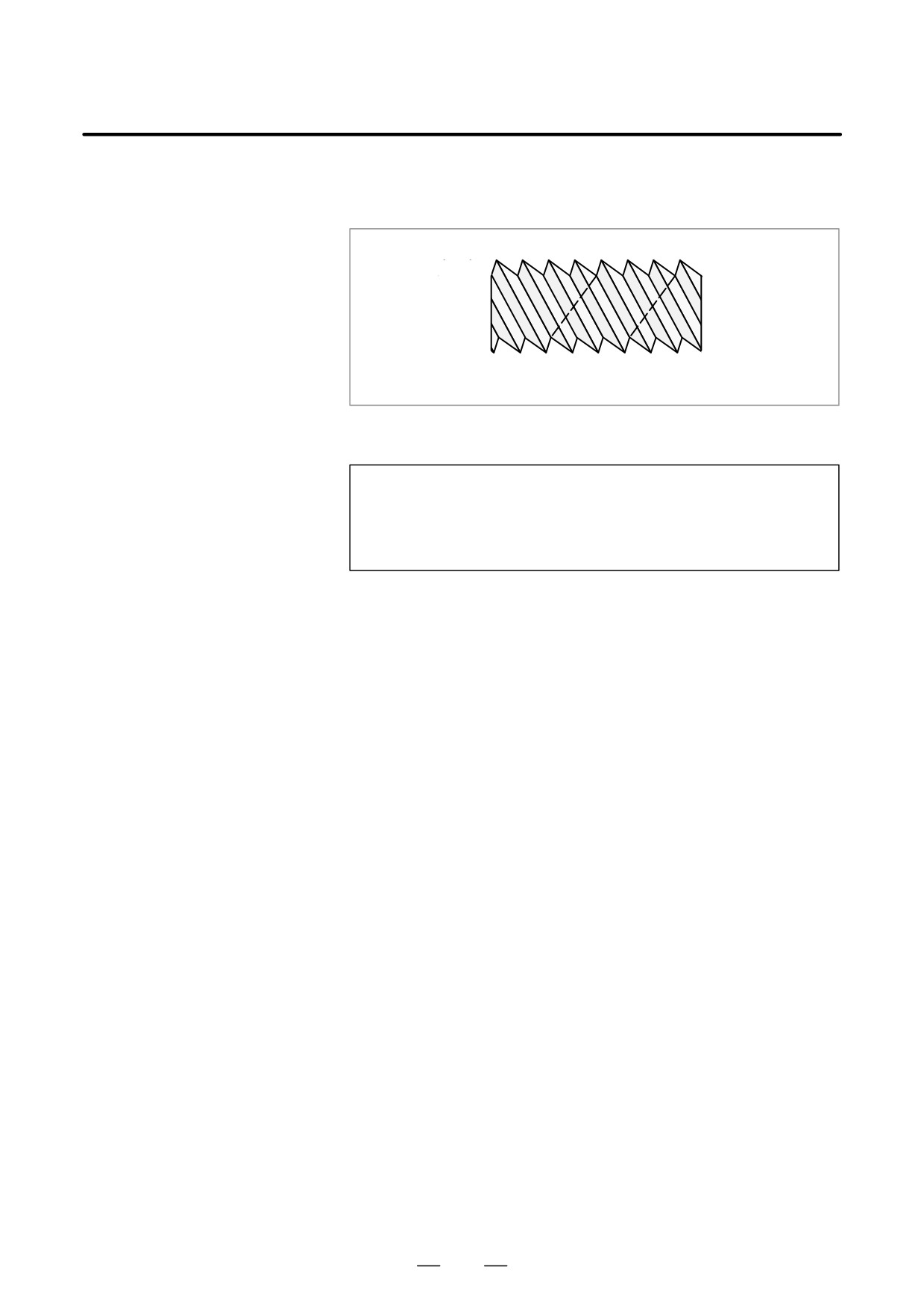
Multiple-thread screws.
Format
(constant-lead threading)
G32 IP_ F_ Q_ ;
IP_ : End point
G32 IP_ Q_ ;
F_ : Lead in longitudinal direction
Q_ : Threading start angle
Explanations
D Available thread cutting
G32: Constant-lead thread cutting
commands
G34: Variable-lead thread cutting
G76: Multiple-thread cutting cycle
G92: Thread cutting cycle
Limitations
D Start angle
The start angle is not a continuous-state (modal) value. It must be
specified each time it is used. If a value is not specified, 0 is assumed.
D Start angle increment
The start angle (Q) increment is 0.001 degrees. Note that no decimal point
can be specified.
Example:
For a shift angle of 180 degrees, specify Q180000.
Q180.000 cannot be specified, because it contains a decimal point.
D Specifiable start angle
A start angle (Q) of between 0 and 360000 (in 0.001-degree units) can be
range
specified. If a value greater than 360000 (360 degrees) is specified, it is
rounded down to 360000 (360 degrees).
D Multiple-thread cutting
For the G76 multiple-thread cutting command, always use the FS15 tape
(G76)
format.
74

B-63524EN/01
PROGRAMMING
4. INTERPOLATION FUNCTIONS
Examples
Program for producing double-threaded screws
(with start angles of 0 and 180 degrees)
G00
X40.0 ;
G32
W-38.0 F4.0 Q0 ;
G00
X72.0 ;
W38.0 ;
X40.0 ;
G32
W-38.0 F4.0 Q180000 ;
G00
X72.0 ;
W38.0 ;
75
4. INTERPOLATION FUNCTIONS
PROGRAMMING
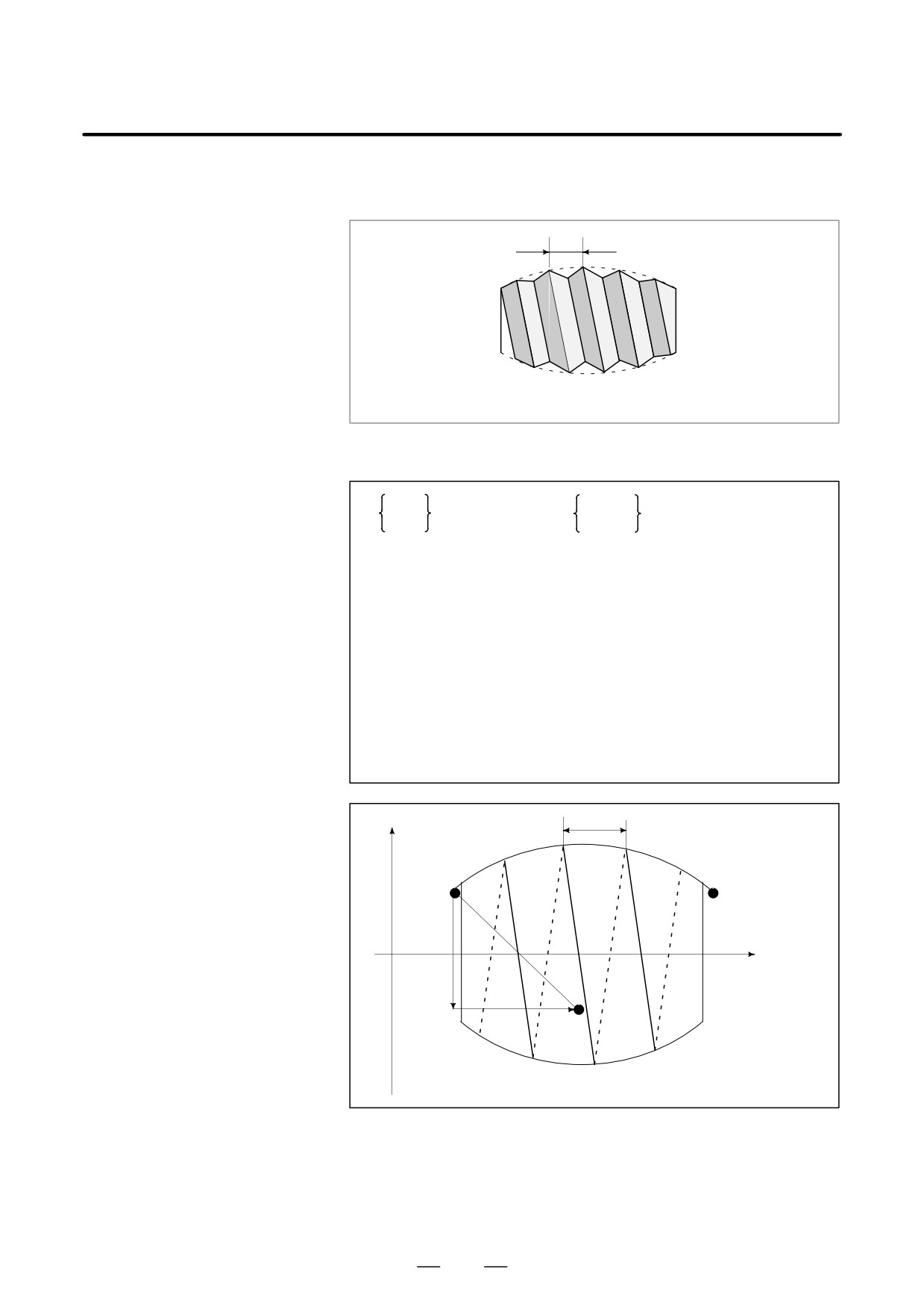
B-63524EN/01
Using the G35 and G36 commands, a circular thread, having the specified
4.13
lead in the direction of the major axis, can be machined.
CIRCULAR
THREADING
L
(G35, G36)
Circular thread
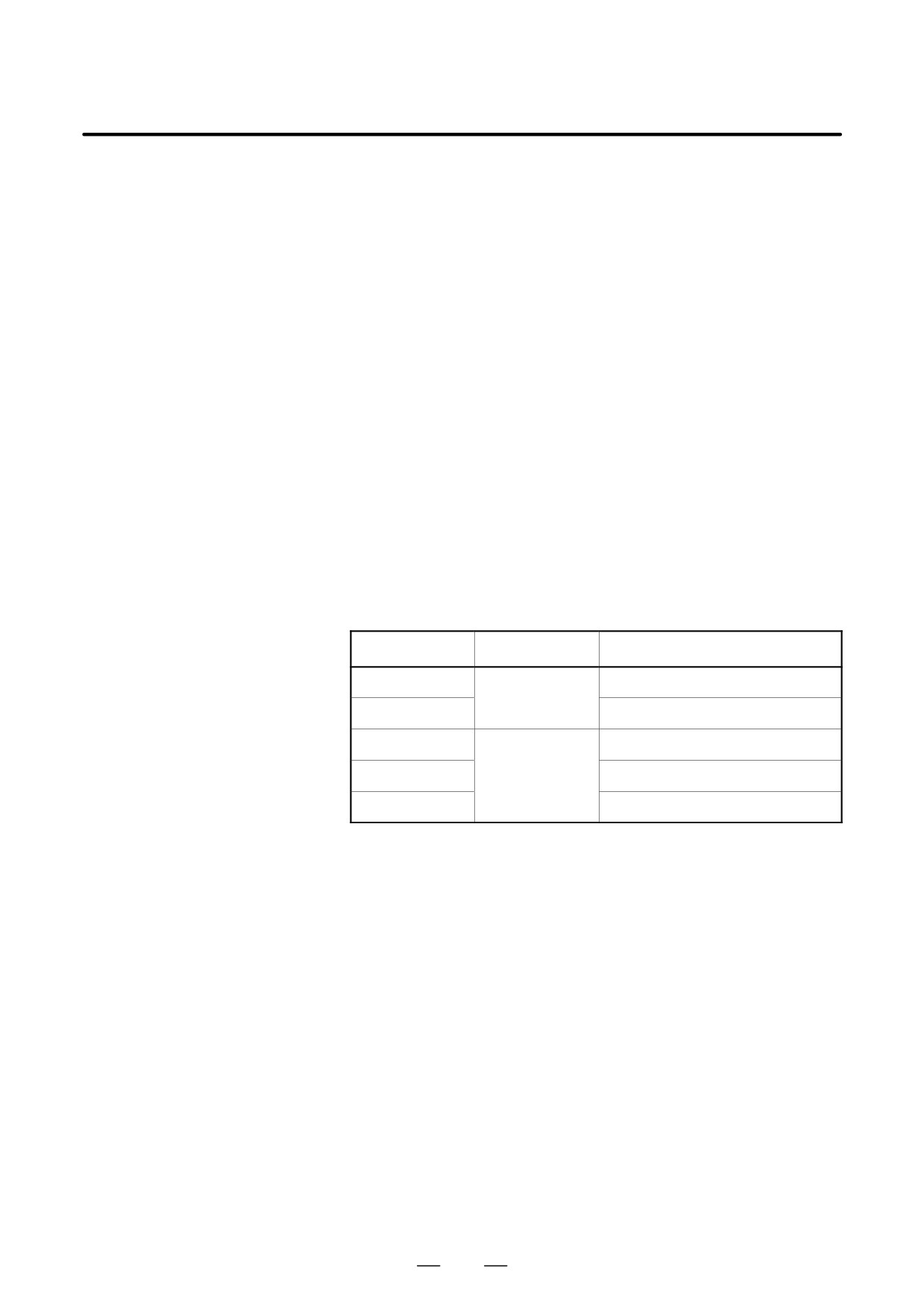
Format
G35
I _ K _
X (U) _ Z (W) _
F _ Q _ ;
G36
R _ _ _
G35
: Clockwise circular threading command
G36
: Counterclockwise circular threading command
X (U) : Specify the arc end point (in the same way as for G02,
G03).
Z (W)
I, K
: Specify the arc center relative to the start point, using
relative coordinates (in the same way as for G02, G03).
R
: Specify the arc radius.
F
: Specify the lead in the direction of the major axis.
Q
: Specify the shift of the threading start angle (0 to 360°
in units of 0.001°)
X
F
Start point
End point (Z, X)
I
R
Z
K
Arc center
76
B-63524EN/01
PROGRAMMING
4. INTERPOLATION FUNCTIONS
Explanations
D Specifying the arc radius
If R is specified with I and K, only R is effective.
D Selecting a plane other
If an additional axis other than the X- and Z-axes is provided, circular
than the ZX plane
threading can be specified for a plane other than the ZX plane. The
method of specification is the same as that for G02 and G03.
D Automatic tool
The G36 command is used to specify the following two functions:
compensation
Automatic tool compensation X and counterclockwise circular threading.
The function for which G36 is to be used depends on bit 3 (G36) of
parameter No. 3405.
D When parameter G36 is set to 0, the G36 command is used for
automatic tool compensation X.
D When parameter G36 is set to 1, the G36 command is used for
counterclockwise circular threading.
G37.1 can be used to specify automatic tool compensation X and G37.2
can be used to specify automatic tool compensation Z.
(Specification method)
G37.1 X_
G37.2 Z_
G code when bit 3 of parameter No. 3405 is set to 1
G code
G code group
Function
G35
Clockwise circular threading
01
G36
Counterclockwise circular threading
G37
Automatic tool compensation Z
G37.1
00
Automatic tool compensation X
G37.2
Automatic tool compensation Z
77
4. INTERPOLATION FUNCTIONS
PROGRAMMING
B-63524EN/01
Limitations
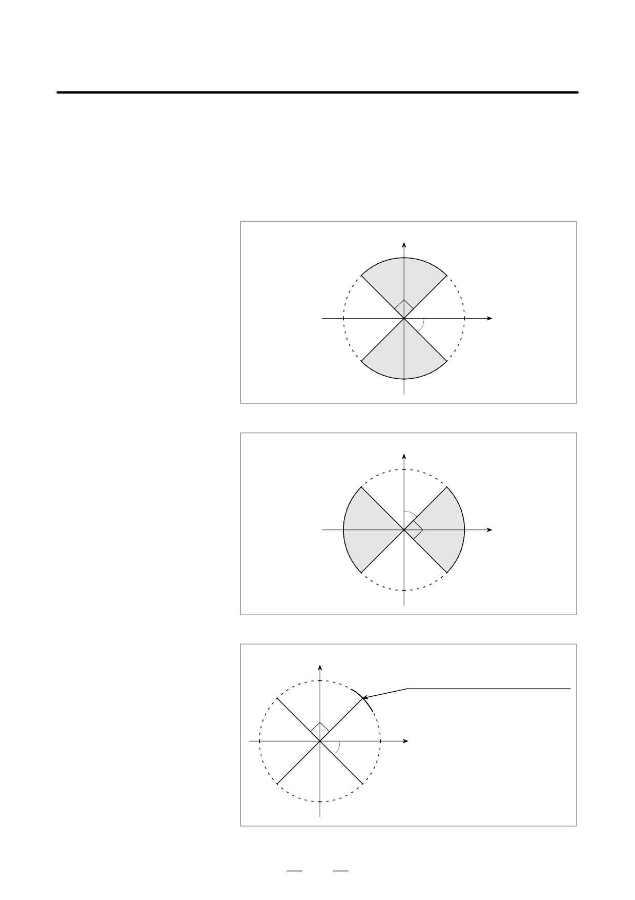
D Range of specifiable arc
An arc must be specified such that it falls within a range in which the
major axis of the arc is always the Z-axis or always the X-axis, as shown
in Fig. 4.13 (a) and (b). If the arc includes a point at which the major axis
changes from the X-axis to Z-axis, or vice versa, as shown in Fig. 4.13
(c), P/S alarm 5058 is issued.
X
Start point
End point
Z
45°
Fig. 4.13 (a) Range in which the Z-axis is the major axis
X
Start point
45°
Z
End point
Fig. 4.13 (b) Range in which the X-axis is the major axis
X
Start point
The major axis changes at this point.
End point
Z
45°
Fig. 4.13 (c) Example of arc specification which causes an alarm
78

B-63524EN/01
PROGRAMMING
4. INTERPOLATION FUNCTIONS
Linear interpolation can be commanded by specifying axial move
4.14
following the G31 command, like G01. If an external skip signal is input
SKIP FUNCTION
during the execution of this command, execution of the command is
(G31)
interrupted and the next block is executed.
The skip function is used when the end of machining is not programmed
but specified with a signal from the machine, for example, in grinding. It
is used also for measuring the dimensions of a workpiece.
For details of how to use this function, refer to the manual supplied by the
machine tool builder.
Format
G31 IP_ ;
G31: One-shot G code (If is effective only in the block in which
it is specified)
Explanations
The coordinate values when the skip signal is turned on can be used in a
custom macro because they are stored in the custom macro system
variable #5061 to #5068, as follows:
#5061 X axis coordinate value
#5062 Z axis coordinate value
#5063 3rd axis coordinate value
:
:
#5068 8th axis coordinate value
WARNING
To increase the precision of the tool position when the skip
signal is input, feedrate override, dry run, and automatic
acceleration/deceleration is disabled for the skip function
when the feedrate is specified as a feed per minute value.
To enable these functions, set bit 7 (SKF) of parameter No.
6200 to 1. If the feedrate is specified as a feed per rotation
value, feedrate override, dry run, and automatic
acceleration/deceleration are enabled for the skip function,
regardless of the setting of the SKF bit.
NOTE
1
If G31 command is issued while tool nose radius
compensation is applied, an P/S alarm of No. 035 is
displayed. Cancel the cutter compensation with the G40
command before the G31 command is specified.
2
For the high-speed skip option, executing G31 during
feed-per- rotation mode causes P/S alarm (No. 211) to be
generated.
79
4. INTERPOLATION FUNCTIONS
PROGRAMMING
B-63524EN/01
Examples
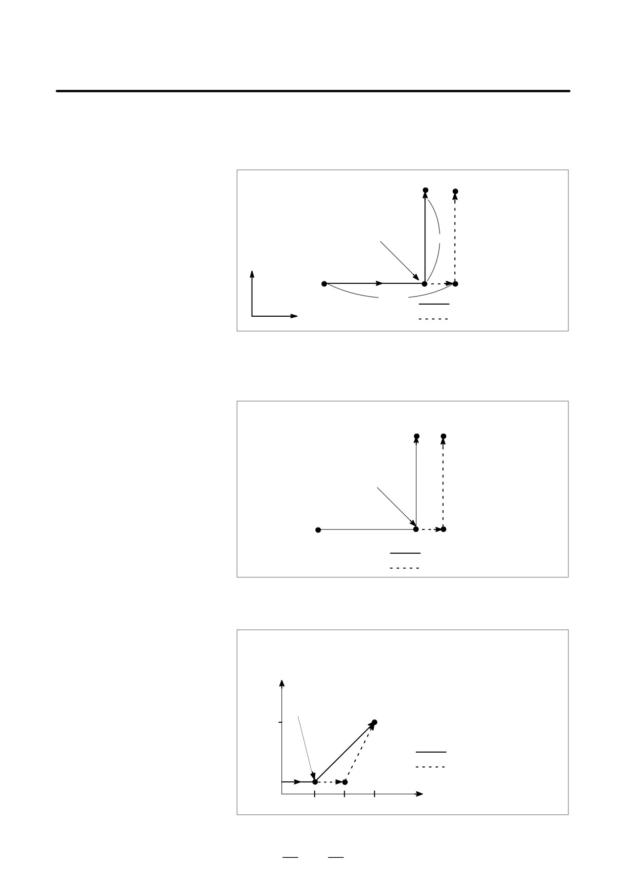
D The next block to G31 is an
incremental command
G31
W100.0 F100;
U50.0;
Skip signal is input here
50.0
X
100.0
Actual motion
Motion without skip signal
Z
Fig.4.14 (a) The next block is an incremental command
D The next block to G31 is an
absolute command for 1
axis
G31
Z200.00 F100;
X100.0
X100.0;
Skip signal is input here
Z200.0
Actual motion
Motion without skip signal
Fig.4.14 (b) The next block is an absolute command for 1 axis
D The next block to G31 is an
absolute command for 2
axes
G31
G90X200.0 F100;
X300.0 Z100.0;
X
Skip signal is input here
100
(100,300)
Actual motion
Motion without skip signal
Z
100
200
300
Fig 4.14 (c) The next block is an absolute command for 2 axes
80

B-63524EN/01
PROGRAMMING
4. INTERPOLATION FUNCTIONS
In a block specifying P1 to P4 after G31, the multistage skip function
4.15
stores coordinates in a custom macro variable when a skip signal (4-point
MULTISTAGE SKIP
or 8-point ; 8-point when a high-speed skip signal is used) is turned on.
(G31)
Then, the function skips the entire amount of remaining movement. In
a block specifying Q1 to Q4 after G04, the function skips a dwell when
a skip signal (4-point or 8-point; 8-point when a high-speed skip signal
is used) is turned on.
A skip signal from equipment such as a fixed-dimension size measuring
instrument can be used to skip programs being executed.
In plunge grinding, for example, a series of operations from rough
machining to spark-out can be performed automatically by applying a
skip signal each time rough machining, semi-fine machining,
fine-machining, or spark-out operation is completed.
For details of how to use this function, refer to the manuals supplied by
the machine tool builder.
Format
Move command
G31 IP __ F __ P __ ;
IP_ : End point
F_ : Feedrate
P_ : P1-P4
Dwell
G04 X (U, P)__ (Q__) ;
X(U, P)_ : Dwell time
Q_ : Q1 - Q4
Explanations
Multistage skip is caused by specifying P1, P2, P3, or P4 in a G31 block.
For an explanation of selecting (P1, P2, P3, or P4), refer to the manual
supplied by the machine tool builder.
Specifying Q1, Q2, Q3, or Q4 in G04 (dwell command) enables dwell
skip in a similar way to specifying G31. A skip may occur even if Q is
not specified. For an explanation of selecting (Q1, Q2, Q3, or Q4), refer
to the manual supplied by the machine tool builder.
D Correspondence to skip
Parameter Nos. 6202 to 6205 can be used to specify whether the 4-point
signals
or 8-point skip signal is used (when a high-speed skip signal is used).
Specification is not limited to one-to-one correspondence. It is possible
to specify that one skip signal correspond to two or more Pn’s or Qn’s
(n=1, 2, 3, 4). Also, bits 0 (DS1) to 7 (DS8) of parameter No. 6206 can
be used to specify dwell.
CAUTION
Dwell is not skipped when Qn is not specified and
parameters DS1-DS8 (No. 6206#0-#7) are not set.
81
4. INTERPOLATION FUNCTIONS
PROGRAMMING
B-63524EN/01
With the motor torque limited (for example, by a torque limit command,
4.16
issued through the PMC window), a move command following G31 P99
TORQUE LIMIT SKIP
(or G31 P98) can cause the same type of cutting feed as with G01 (linear
(G31 P99)
interpolation).
With the issue of a signal indicating a torque limit has been reached
(because of pressure being applied or for some other reason), a skip
occurs.
For details of how to use this function, refer to the manuals supplied by
the machine tool builder.
Format
G31 P99 IP_ F_ ;
G31 P98 IP_ F_ ;
G31: One-shot G code (G code effective only in the block in which it
is issued)
Explanations
D G31 P99
If the motor torque limit is reached, or a SKIP signal is received during
execution of G31 P99, the current move command is aborted, and the next
block is executed.
D G31 P98
If the motor torque limit is reached during execution of G31 P98, the
current move command is aborted, and the next block is executed. The
SKIP signal <X0004#7/Tool post 2 X0013#7> does not affect G31 P98.
Entering a SKIP signal during the execution of G31 P98 does not cause
a skip.
D Torque limit command
If a torque limit is not specified before the execution of G31 P99/98, the
move command continues; no skip occurs even if a torque limit is
reached.
D Custom macro system
When G31 P99/98 is specified, the custom macro variables hold the
variable
coordinates at the end of a skip.
(See Section 4.9.)
If a SKIP signal causes a skip with G31 P99, the custom macro system
variables hold the coordinates based on the machine coordinate system
when it stops, rather than those when the SKIP signal is entered.
Limitations
D Axis command
Only one axis can be controlled in each block with G31 P98/99.
If two or more axes are specified to be controlled in such blocks, or no axis
command is issued, P/S alarm No. 015 is generated.
D Degree of servo error
When a signal indicating that a torque limit has been reached is input
during execution of G31 P99/98, and the degree of servo error exceeds
32767, P/S alarm No. 244 is generated.
D High-speed skip
With G31 P99, a SKIP signal can cause a skip, but not a high-speed skip.
82
B-63524EN/01
PROGRAMMING
4. INTERPOLATION FUNCTIONS
D Simplified
G31 P99/98 cannot be used for axes subject to simplified synchronization
synchronization and
or the X-axis or Z-axis when under slanted axis control.
slanted axis control
D Speed control
Bit 7 (SKF) of parameter No. 6200 must be set to disable dry run,
override, and auto acceleration or deceleration for G31 skip commands.
Do not use G31 P99/98 in consecutive blocks.
D Consecutive commands
WARNING
Always specify a torque limit before a G31 P99/98
command.
Otherwise, G31 P99/98 allows move
commands to be executed without causing a skip.
NOTE
If G31 is issued with tool nose radius compensation
specified, P/S alarm No. 035 is generated. Therefore,
before issuing G31, execute G40 to cancel tool nose radius
compensation.
Examples
O0001 ;
:
:
Mjj ;
The PMC specifies the torque limit
:
through the window.
:
G31 P99 X200. F100 ;
Torque limit skip command
:
Move command for which a torque
G01 X100. F500 ;
limit is applied
:
:
MDD ;
Torque limit canceled by the PMC
:
:
M30 ;
:
%
83
5. FEED FUNCTIONS
PROGRAMMING
B-63524EN/01
FEED FUNCTIONS
5
84
B-63524EN/01
PROGRAMMING
5. FEED FUNCTIONS
The feed functions control the feedrate of the tool. The following two feed
5.1
functions are available:
GENERAL
D Feed functions
1. Rapid traverse
When the positioning command (G00) is specified, the tool moves at!a
rapid traverse feedrate set in the CNC (parameter No. 1420).
2. Cutting feed
The tool moves at a programmed cutting feedrate.
D Override
Override can be applied to a rapid traverse rate or cutting feedrate using
the switch on the machine operator’s panel.
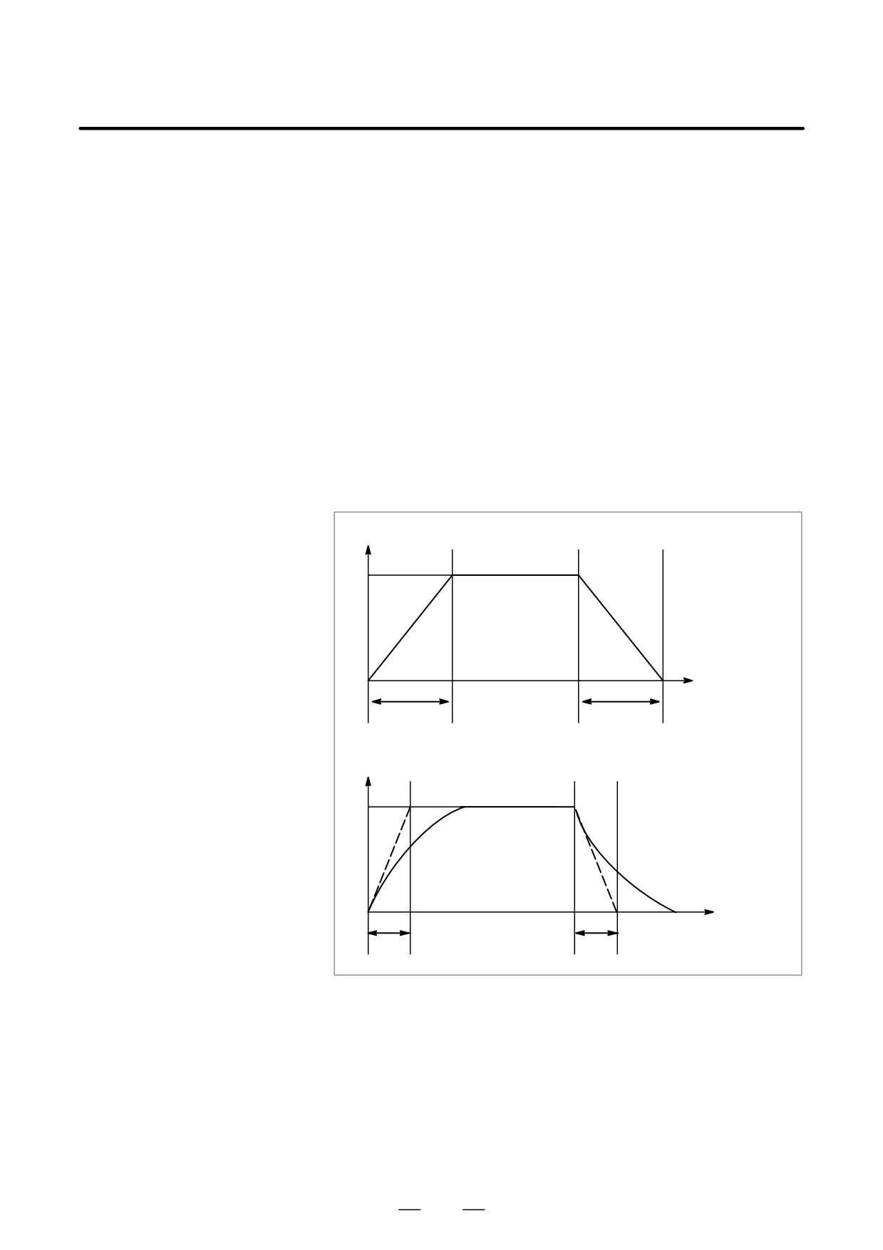
D Automatic acceleration/
To prevent a mechanical shock, acceleration/deceleration is automatically
deceleration
applied when the tool starts and ends its movement (Fig. 5.1 (a)).
Rapid traverse rate
FR :Rapid traverse
FR
rate
: Acceleration/
TR
deceleration
time constant for
rapid traverse
rate
0
Time
TR
TR
Feed rate
FC
: Feedrate
FC
TC : Acceleration/
deceleration time
constant for a cut-
ting feedrate
0
Time
TC
TC
Fig. 5.1 (a) Automatic acceleration/deceleration (example)
85
5. FEED FUNCTIONS
PROGRAMMING
B-63524EN/01
D Tool path in a cutting
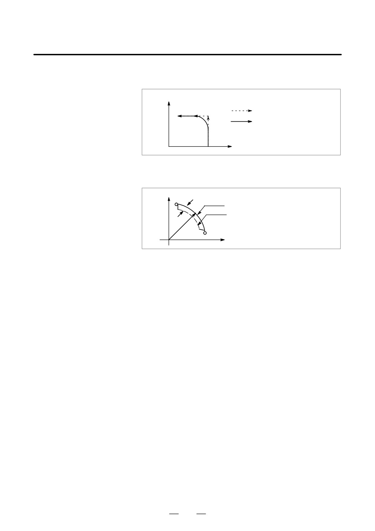
If the direction of movement changes between specified blocks during
feed
cutting feed, a rounded-corner path may result (Fig. 5.1 (b)).
X
Programmed path
Actual tool path
Z
0
Fig. 5.1 (b) Example of Tool Path between Two Blocks
In circular interpolation, a radial error occurs (Fig. 5.1 (c)).
X
∆r:Error
Programmed path
Actual tool path
r
Z
0
Fig. 5.1 (c) Example of Radial Error in Circular Interpolation
The rounded-corner path shown in Fig. 5.1 (b) and the error shown in Fig.
5.1 (c) depend on the feedrate. So, the feedrate needs to be controlled for
the tool to move as programmed.
86
B-63524EN/01
PROGRAMMING
5. FEED FUNCTIONS
5.2
RAPID TRAVERSE
Format
G00 IP_ ;
G00 : G code (group 01) for positioning (rapid traverse)
IP_ ; Dimension word for the end point
Explanations
The positioning command (G00) positions the tool by rapid traverse. In
rapid traverse, the next block is executed after the specified feedrate
becomes 0 and the servo motor reaches a certain range set by the machine
tool builder (in-position check).
A rapid traverse rate is set for each axis by parameter No. 1420, so no rapid
traverse feedrate need be programmed.
The following overrides can be applied to a rapid traverse rate with the
switch on the machine operator’s panel:F0, 25, 50, 100%
F0: Allows a fixed feedrate to be set for each axis by parameter No. 1421.
For detailed information, refer to the appropriate manual of the machine
tool builder.
87
5. FEED FUNCTIONS
PROGRAMMING
B-63524EN/01
Feedrate of linear interpolation (G01), circular interpolation (G02, G03),
5.3
etc. are commanded with numbers after the F code.
CUTTING FEED
In cutting feed, the next block is executed so that the feedrate change from
the previous block is minimized.
Two modes of specification are available:
1. Feed per minute (G98)
After F, specify the amount of feed of the tool per minute.
2. Feed per revolution (G99)
After F, specify the amount of feed of the tool per spindle revolution.
Format
Feed per minute
G98 ; G code (group 05) for feed per minute
F_ ;
Feedrate command (mm/min or inch/min)
Feed per revolution
G99 ; G code (group 05) for feed per revolution
F_ ;
Feedrate command (mm/rev or inch/rev)
Explanations
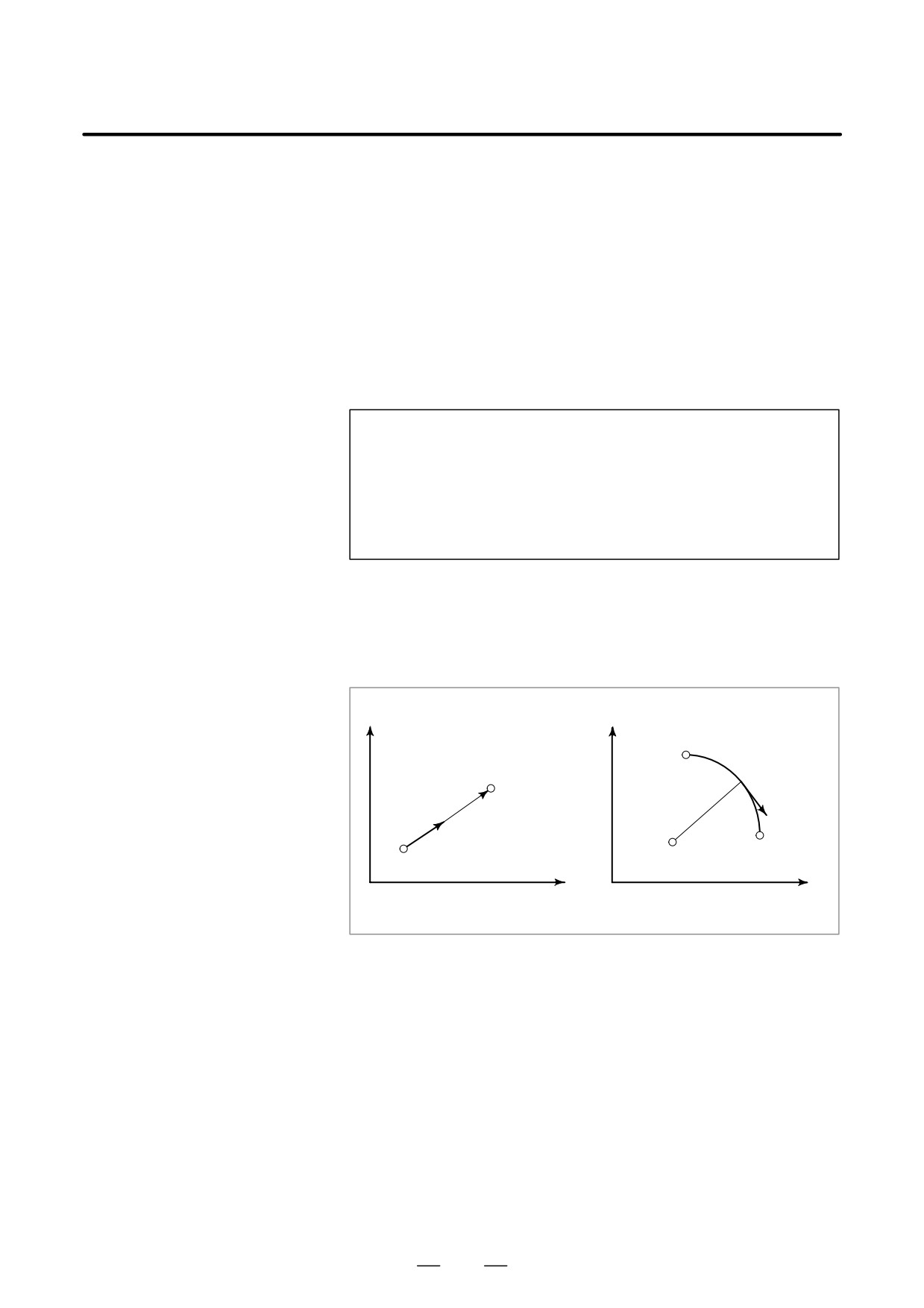
D Tangential speed
Cutting feed is controlled so that the tangential feedrate is always set at
constant control
a specified feedrate.
X
X
Starting
End point
point
F
F
Start
Center
End point
point
Z
Z
Linear interpolation
Circular interpolation
Fig. 5.3 (a) Tangential feedrate (F)
After specifying G98 (in the feed per minute mode), the amount of feed
D Feed per minute (G98)
of the tool per minute is to be directly specified by setting a number after
F. G98 is a modal code. Once a G98 is specified, it is valid until G99 (feed
per revolution) is specified. At power-on, the feed per revolution mode
is set.
An override from 0% to 254% (in 1% steps) can be applied to feed per
minute with the switch on the machine operator’s panel. For detailed
information, see the appropriate manual of the machine tool builder.
88
B-63524EN/01
PROGRAMMING
5. FEED FUNCTIONS
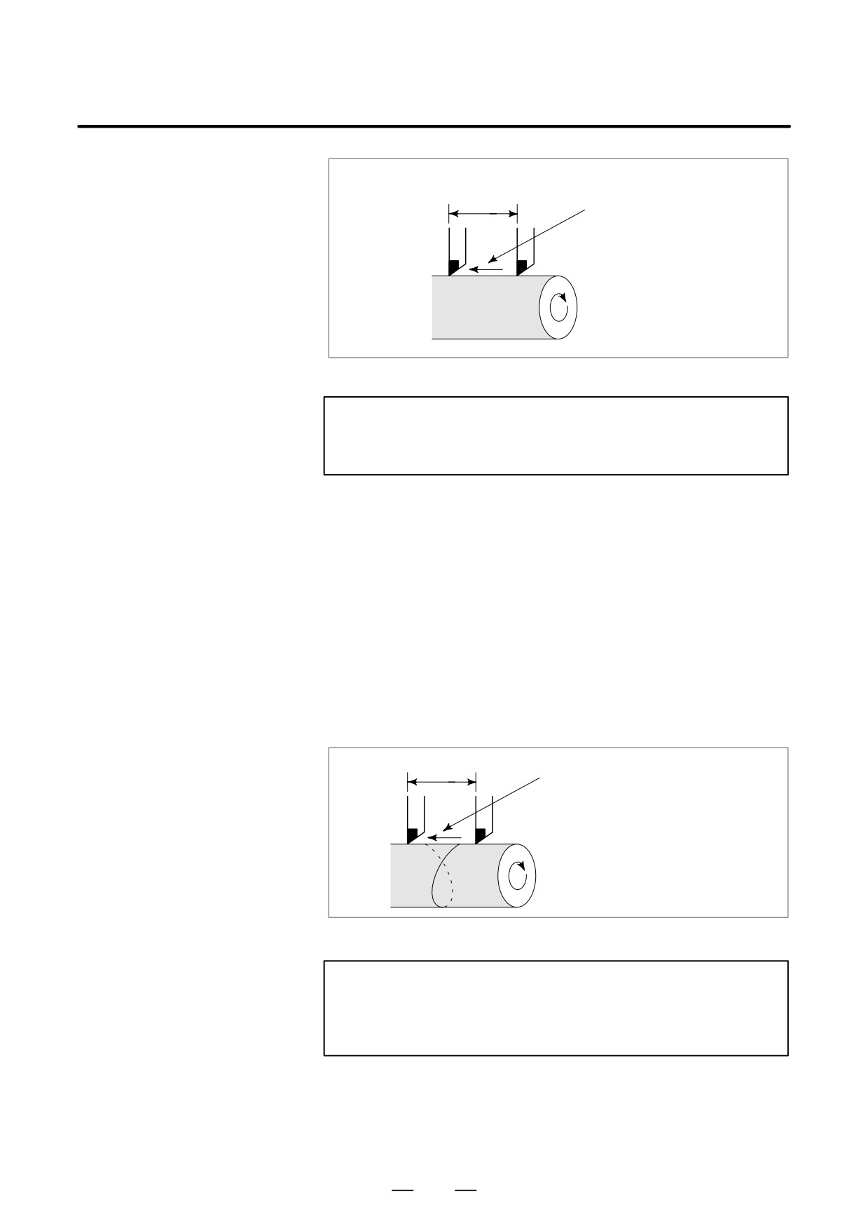
Feed amount per minute
F
(mm/min or inch/min)
Fig. 5.3 (b) Feed per minute
WARNING
No override can be used for some commands such as for
threading.
D Feed per revolution
After specifying G99 (in the feed per revolution mode), the amount of
(G99)
feed of the tool per spindle revolution is to be directly specified by setting
a number after F. G99 is a modal code. Once a G99 is specified, it is valid
until G98 (feed per minute) is specified.
An override from 0% to 254% (in 1% steps) can be applied to feed per
revolution with the switch on the machine operator’s panel. For detailed
information, see the appropriate manual of the machine tool builder.
If bit 0 (NPC) of parameter No. 1402 has been set to 1, feed-per-rotation
commands can be specified even when a position coder is not being used.
(The CNC converts feed-per-rotation commands to feed-per-minute
commands.)
F
Feed amount per spindle revolution
(mm/rev or inch/rev)
Fig. 5.3 (c) Feed per revolution
CAUTION
When the speed of the spindle is low, feedrate fluctuation
may occur. The slower the spindle rotates, the more
frequently feedrate fluctuation occurs.
A common upper limit can be set on the cutting feedrate along each axis
D Cutting feedrate clamp
with parameter No. 1422. If an actual cutting feedrate (with an override
applied) exceeds a specified upper limit, it is clamped to the upper limit.
89
5. FEED FUNCTIONS
PROGRAMMING
B-63524EN/01
NOTE
An upper limit is set in mm/min or inch/min. CNC calculation
may involve a feedrate error of "2% with respect to a
specified value.
However, this is not true for
acceleration/deceleration. To be more specific, this error is
calculated with respect to a measurement on the time the
tool takes to move 500 mm or more during the steady state:
D Reference
See Appendix C for a range of feedrates that can be specified.
90
B-63524EN/01
PROGRAMMING
5. FEED FUNCTIONS
5.4
DWELL (G04)
Format
Dwell G04 X_ ; or G04 U_ ; or G04 P_ ;
X_ : Specify a time (decimal point permitted)
U_ : Specify a time (decimal point permitted)
P_ : Specify a time (decimal point not permitted)
Explanations
By specifying a dwell, the execution of the next block is delayed by the
specified time.
Bit 1 (DWL) of parameter No. 3405 can specify dwell for each rotation
in feed per rotation mode (G99).
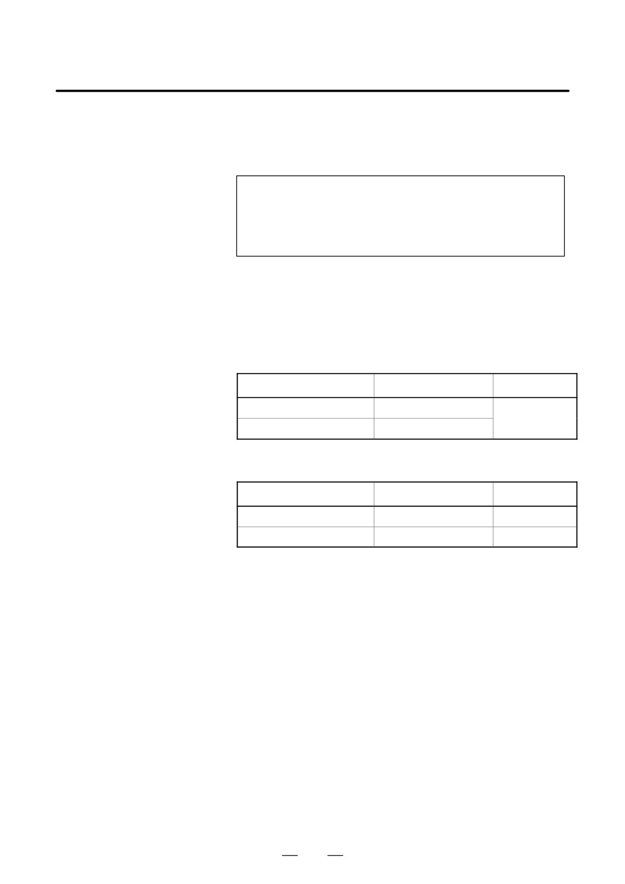
Table 5.4 (a)
Command value range of the dwell time (Command by X or U)
Increment system
Command value range
Dwell time unit
IS-B
0.001 to 99999.999
s or rev
IS-C
0.0001 to 9999.9999
Table 5.4 (b)
Command value range of the dwell time (Command by P)
Increment system
Command value range
Dwell time unit
IS-B
1 to 99999999
0.001 s or rev
IS-C
1 to 99999999
0.0001 s or rev
91
6. REFERENCE POSITION
PROGRAMMING
B-63524EN/01
REFERENCE POSITION
6
A CNC machine tool has a special position where, generally, the tool is
exchanged or the coordinate system is set, as described later. This
position is referred to as a reference position.
92
B-63524EN/01
PROGRAMMING
6. REFERENCE POSITION
6.1
REFERENCE
POSITION RETURN
D Reference position
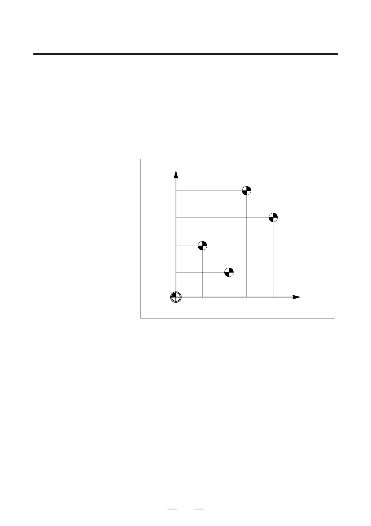
The reference position is a fixed position on a machine tool to which the
tool can easily be moved by the reference position return function.
For example, the reference position is used as a position at which tools
are automatically changed. Up to four reference positions can be
specified by setting coordinates in the machine coordinate system in
parameters (No. 1240 to 1243).
Y
2nd reference position
3rd reference position
Reference position
4th reference
position
X
Machine zero point
Fig. 6.1 (a) Machine zero point and reference positions
93
6. REFERENCE POSITION
PROGRAMMING
B-63524EN/01
D Reference position
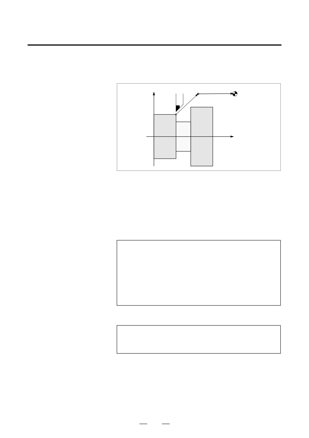
Tools are automatically moved to the reference position via an
return
intermediate position along a specified axis. When reference position
return is completed, the lamp for indicating the completion of return goes
on.
Intermediate position
X
Reference position
Z
Fig. 6.2 (b) Reference position return
D Reference position
The reference position return check (G27) is the function which checks
return check
whether the tool has correctly returned to the reference position as
specified in the program. If the tool has correctly returned to the reference
position along a specified axis, the lamp for the axis goes on.
Format
D Reference position
return
G28IP
_ ;
Reference position return
G30 P2
IP
_ ;2nd reference position return
(P2 can
be omitted.)
G30 P3
IP
_ ;3rd reference position return
4th reference position return
G30 P4
IP
_ ;
IP : Command specifying the intermediate position
(Absolute/incremental command)
D Reference position
return check
G27 IP _ ;
IP : Command specifying the reference position
(Absolute/incremental command)
94
B-63524EN/01
PROGRAMMING
6. REFERENCE POSITION
Explanations
D Reference position
Positioning to the intermediate or reference positions are performed at the
return (G28)
rapid traverse rate of each axis.
Therefore, for safety, the tool nose radius compensation, and tool offset
should be cancelled before executing this command.
D 2nd, 3rd, and 4th
In a system without an absolute-position detector, the first, third, and
reference position return
fourth reference position return functions can be used only after the
(G30)
reference position return (G28) or manual reference position return (see
III-3.1) is made. The G30 command is generally used when the automatic
tool changer (ATC) position differs from the reference position.
D Reference position
G27 command positions the tool at rapid traverse rate. If the tool reaches
return check (G27)
the reference position, the reference position return lamp lights up.
However, if the position reached by the tool is not the reference position,
an alarm (No. 092) is displayed.
Restrictions
D Status the machine lock
The lamp for indicating the completion of return does not go on when the
being turned on
machine lock is turned on, even when the tool has automatically returned
to the reference position. In this case, it is not checked whether the tool
has returned to the reference position even when a G27 command is
specified.
D First return to the
When the G28 command is specified when manual return to the reference
reference position after
position has not been performed after the power has been turned on, the
the power has been
movement from the intermediate point is the same as in manual return to
turned on (without an
the reference position.
absolute position
In this case, the tool moves in the direction for reference position return
detector)
specified in parameter ZMIx (bit 5 of No. 1006). Therefore the specified
intermediate position must be a position to which reference position
return is possible.
D Reference position
In an offset mode, the position to be reached by the tool with the G27
return check in an offset
command is the position obtained by adding the offset value. Therefore,
mode
if the position with the offset value added is not the reference position, the
lamp does not light up, but an alarm is displayed instead. Usually, cancel
offsets before G27 is commanded.
D Lighting the lamp when
When the machine tool is an inch system with metric input, the reference
the programmed position
position return lamp may also light up even if the programmed position
does not coincide with
is shifted from the reference position by least input increment. This is
the reference position
because the least input increment of the machine is smaller than its least
command increment.
Reference
D Manual reference
See III-3.1.
position return
95
6. REFERENCE POSITION
PROGRAMMING
B-63524EN/01
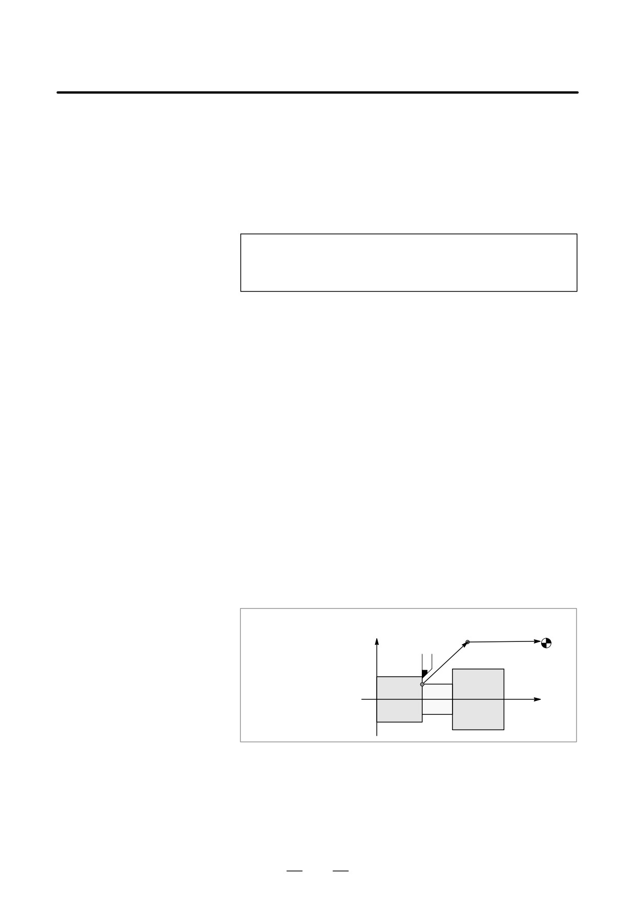
Tools ca be returned to the floating reference position.
6.2
A floating reference point is a position on a machine tool, and serves as
FLOATING
a reference point for machine tool operation.
REFERENCE
A floating reference point need not always be fixed, but can be moved as
POSITION RETURN
required.
(G30.1)
Format
G30.1
IP
;
IP _ : Command of the intermediate position of the floating reference
position
(Absolute command/incremental command)
Explanations
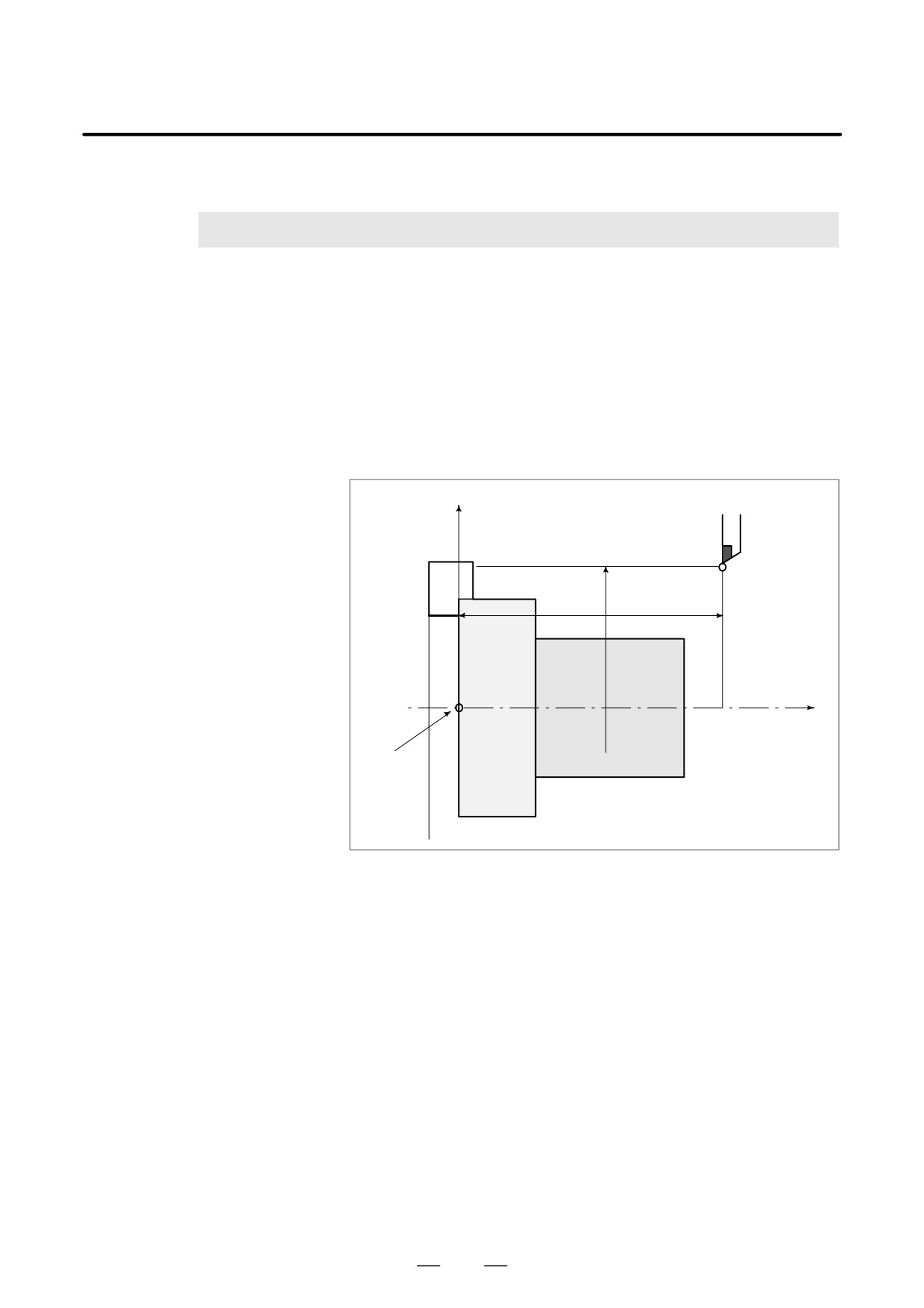
On some machine tools, the cutting tools can be replaced at any position
unless they interfere with the workpiece or tail stock.
With these machines, the cutting tools should be replaced at a position as
close to the workpiece as possible so as to minimize the machine cycle
time. For this purpose, the tool change position is to be changed,
depending on the figure of the workpiece. This operation can easily be
performed using this function. That is, a tool change position suitable for
the workpiece is memorized as a floating reference point. Then command
G30. 1 can easily cause return to the tool change position.
D Floating reference
The G30.1 block first positions the tool at the intermediate point along the
position
specified axes at rapid traverse rate, then further moves the tool from the
intermediate point to the floating reference point at rapid traverse rate.
Before using G30.1, cancel cutter compensation and tool offset.
D Setting of floating
A floating reference point becomes a machine coordinate position
reference position
memorized by pressing the soft key [SET FRP] on the current positions
display screen.
A floating reference point is not lost even if power is turned off.
Examples
G30.1 X40.0 Z50.0 ;
Intermediate position (40, 50)
X
Floating
reference
Workpiece
position
Z
96
B-63524EN/01
PROGRAMMING
7. COORDINATE SYSTEM
COORDINATE SYSTEM
7
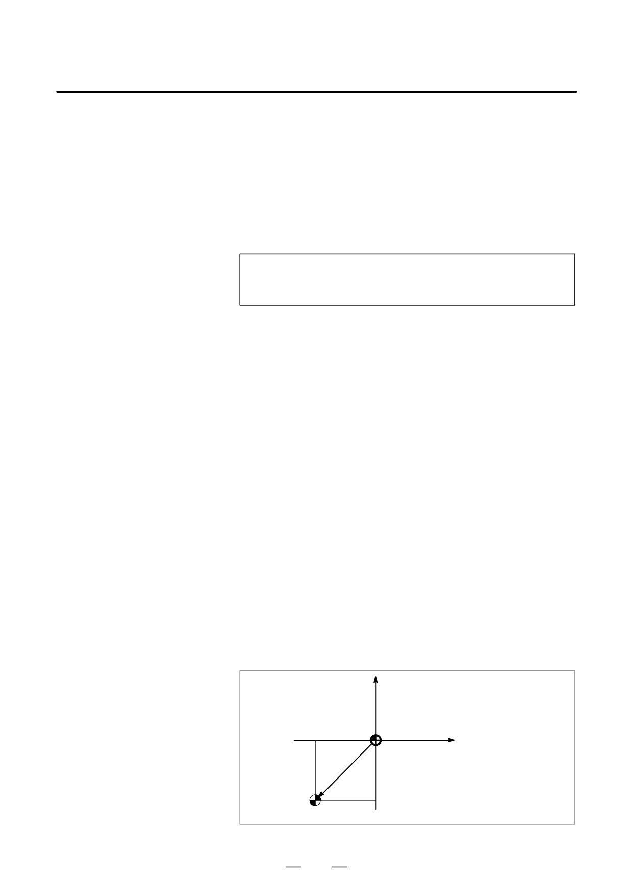
By teaching the CNC a desired tool position, the tool can be moved to the
position. Such a tool position is represented by coordinates in a
coordinate system. Coordinates are specified using program axes.
When two program axes, the X-axis and Z-axis, are used, coordinates
are specified as follows:
X_Z_
This command is referred to as a dimension word.
X
ÎÎÎ
ÎÎÎ
β
ÎÎ
α
Z
Zero point
Fig. 7 Tool Position Specified by XαZβ
Coordinates are specified in one of following three coordinate systems:
(1) Machine coordinate system
(2) Workpiece coordinate system
(3) Local coordinate system
The number of the axes of a coordinate system varies from one machine
to another. So, in this manual, a dimension word is represented as IP_.
97
7. COORDINATE SYSTEM
PROGRAMMING
B-63524EN/01
The point that is specific to a machine and serves as the reference of the
7.1
machine is referred to as the machine zero point. A machine tool builder
MACHINE
sets a machine zero point for each machine.
COORDINATE
A coordinate system with a machine zero point set as its origin is referred
SYSTEM
to as a machine coordinate system.
A machine coordinate system is set by performing manual reference
position return after power-on (see III-3.1). A machine coordinate
system, once set, remains unchanged until the power is turned off.
Format
G53 IP _ ;
IP _; Absolute dimension word
Explanations
D Selecting a machine
When a position has been specified as a set of machine coordinates, the
coordinate system (G53)
tool moves to that position by means of rapid traverse. G53, used for
selecting the machine coordinate system, is a one-shot G code. Any
commands based on the selected machine coordinate system are thus
effective only in the block containing G53. The G53 command must be
specified using absolute values. If incremental values are specified, the
G53 command is ignored. When the tool is to be moved to a
machine-specific position such as a tool change position, program the
movement in a machine coordinate system based on G53.
Restrictions
D Cancel of the
When the G53 command is specified, cancel the tool nose radius
compensation function
compensation and tool offset.
D G53 specification
Since the machine coordinate system must be set before the G53
immediately after
command is specified, at least one manual reference position return or
power-on
automatic reference position return by the G28 command must be
performed after the power is turned on. This is not necessary when an
absolute-position detector is attached.
Reference
When manual reference position return is performed after power-on, a
machine coordinate system is set so that the reference position is at the
coordinate values of (α, β) set using parameter No.1240.
Machine coordinate system
Machine zero
β
α
Reference position
98