FANUC Series Series 16i-TB, Series 18i-TB, Series 160i-TB, Series 180i-TB. OPERATOR’S MANUAL - page 3
3. PREPARATORY FUNCTION
B-63524EN/01
PROGRAMMING
(G FUNCTION)
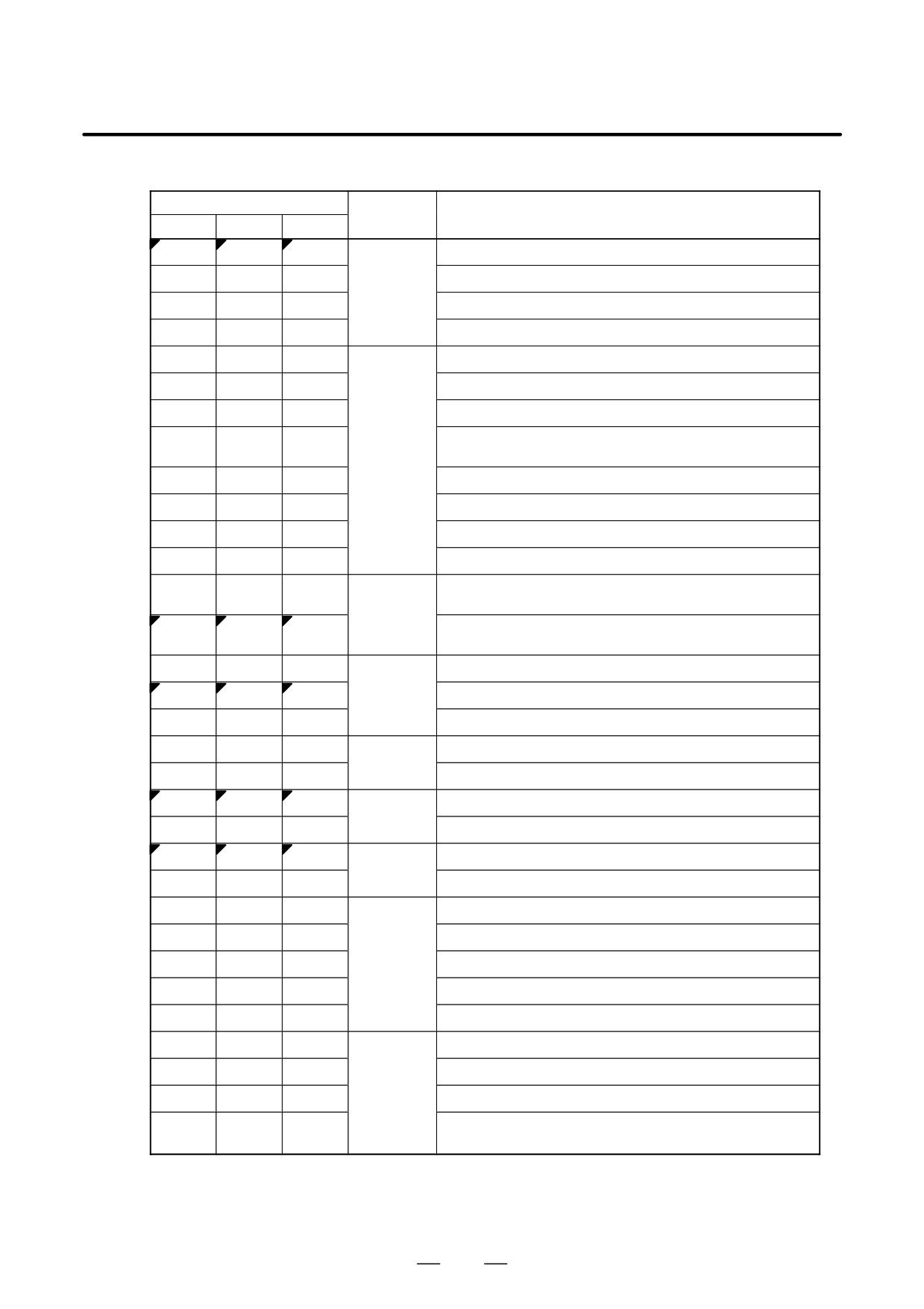
Table 3 G code list for T series (1/3)
G code
Group
Function
A
B
C
G00
G00
G00
Positioning (Rapid traverse)
G01
G01
G01
Linear interpolation (Cutting feed)
01
G02
G02
G02
Circular interpolation CW or helical interpolation CW
G03
G03
G03
Circular interpolation CCW or helical interpolation CCW
G04
G04
G04
Dwell
G05
G05
G05
High-speed cycle cutting
G07
G07
G07
Hypothetical axis interpolation
G07.1
G07.1
G07.1
Cylindrical interpolation
(G107)
(G107)
(G107)
00
G08
G08
G08
Look-ahead control
G10
G10
G10
Programmable data input
G10.6
G10.6
G10.6
Tool retract and return
G11
G11
G11
Programmable data input mode cancel
G12.1
G12.1
G12.1
Polar coordinate interpolation mode
(G112)
(G112)
(G112)
21
G13.1
G13.1
G13.1
Polar coordinate interpolation cancel mode
(G113)
(G113)
(G113)
G17
G17
G17
XpYp plane selection
G18
G18
G18
16
ZpXp plane selection
G19
G19
G19
YpZp plane selection
G20
G20
G70
Input in inch
06
G21
G21
G71
Input in mm
G22
G22
G22
Stored stroke check function on
09
G23
G23
G23
Stored stroke check function off
G25
G25
G25
Spindle speed fluctuation detection off
08
G26
G26
G26
Spindle speed fluctuation detection on
G27
G27
G27
Reference position return check
G28
G28
G28
Return to reference position
G30
G30
G30
00
2nd, 3rd and 4th reference position return
G30.1
G30.1
G30.1
Floating reference point return
G31
G31
G31
Skip function
G32
G33
G33
Thread cutting
G34
G34
G34
Variable-lead thread cutting
01
G35
G35
G35
Circular threading CW
Circular threading CCW (When the bit 3 (G36) of parameter
G36
G36
G36
No. 3405 is set to 1)
39
3.
PREPARATORY FUNCTION
(G FUNCTION)
PROGRAMMING
B-63524EN/01
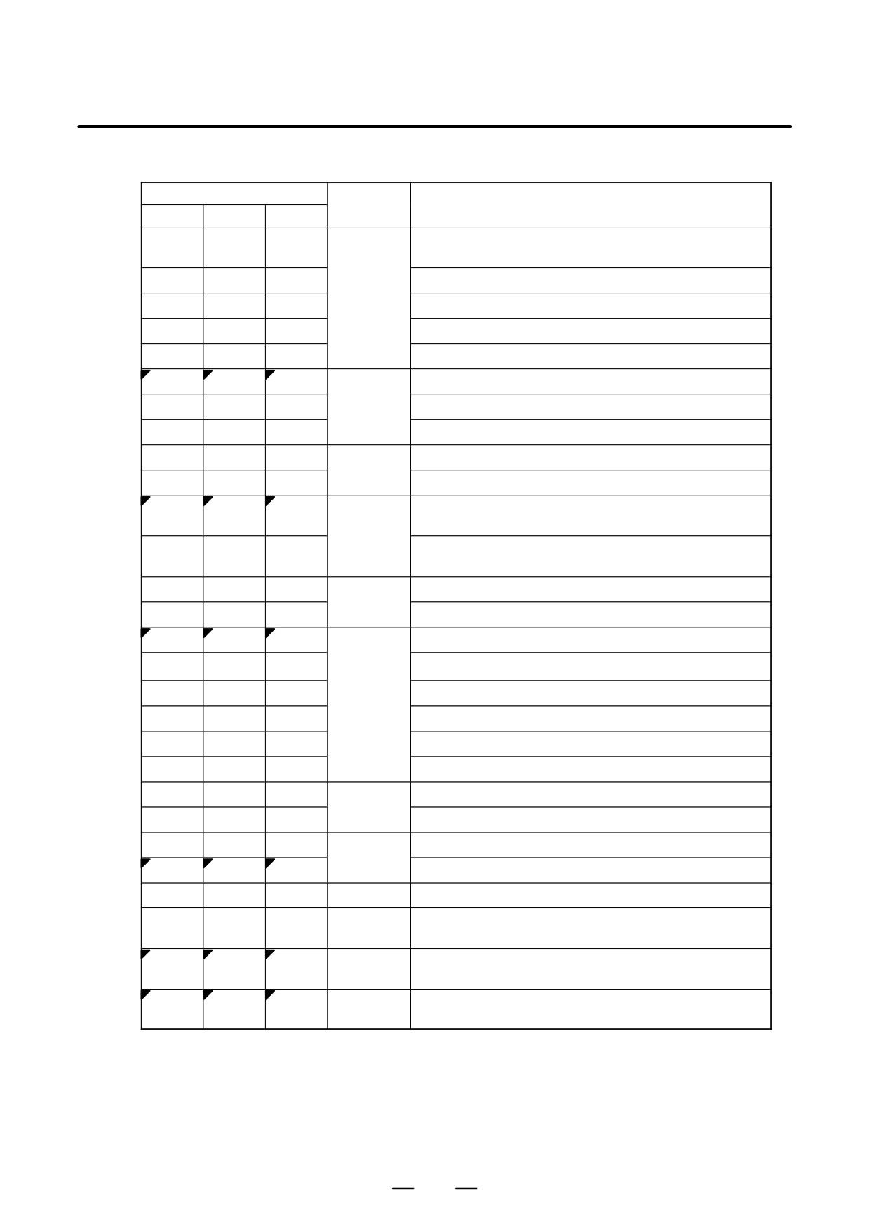
Table 3 G code list for T series (2/3)
G code
Group
Function
A
B
C
Automatic tool compensation X (When the bit 3 (G36) of
G36
G36
G36
parameter No. 3405 is set to 0)
G37
G37
G37
Automatic tool compensation Z
00
G37.1
G37.1
G37.1
Automatic tool compensation X
G37.2
G37.2
G37.2
Automatic tool compensation Z
G39
G39
G39
Corner circular interpolation
G40
G40
G40
Tool nose radius compensation cancel
G41
G41
G41
07
Tool nose radius compensation left
G42
G42
G42
Tool nose radius compensation right
G50
G92
G92
Coordinate system setting or max. spindle speed setting
00
G50.3
G92.1
G92.1
Workpiece coordinate system preset
G50.2
G50.2
G50.2
Polygonal turning cancel
(G250)
(G250)
(G250)
20
G51.2
G51.2
G51.2
Polygonal turning
(G251)
(G251)
(G251)
G52
G52
G52
Local coordinate system setting
00
G53
G53
G53
Machine coordinate system setting
G54
G54
G54
Workpiece coordinate system 1 selection
G55
G55
G55
Workpiece coordinate system 2 selection
G56
G56
G56
Workpiece coordinate system 3 selection
14
G57
G57
G57
Workpiece coordinate system 4 selection
G58
G58
G58
Workpiece coordinate system 5 selection
G59
G59
G59
Workpiece coordinate system 6 selection
G60
G60
G60
Single direction positioning
00
G65
G65
G65
Macro calling
G66
G66
G66
Macro modal call
12
G67
G67
G67
Macro modal call cancel
G68
G68
G68
04
Mirror image for double turrets ON or balance cut mode
Coordinate system rotation start or three-dimensional coor-
G68.1
G68.1
G68.1
17
dinate system conversion mode on
Mirror image for double turrets OFF or balance cut mode
G69
G69
G69
04
cancel
Coordinate system rotation cancel or three-dimensional
G69.1
G69.1
G69.1
17
coordinate system conversion mode off
40
3. PREPARATORY FUNCTION
B-63524EN/01
PROGRAMMING
(G FUNCTION)
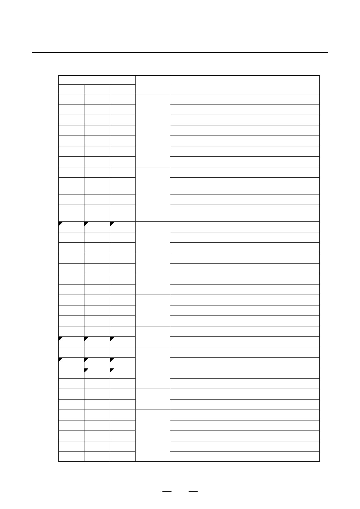
Table 3 G code list for T series (3/3)
G code
Group
Function
A
B
C
G70
G70
G72
Finishing cycle
G71
G71
G73
Stock removal in turning
G72
G72
G74
Stock removal in facing
G73
G73
G75
00
Pattern repeating
G74
G74
G76
End face peck drilling
G75
G75
G77
Outer diameter/internal diameter drilling
G76
G76
G78
Multiple threading cycle
G71
G71
G72
Traverse grinding cycle (for grinding machine)
Traverse direct constant-dimension grinding cycle
G72
G72
G73
01
(for grinding machine)
G73
G73
G74
Oscilation grinding cycle (for grinding machine)
Oscilation direct constant-dimension grinding cycle
G74
G74
G75
(for grinding machine)
G80
G80
G80
Canned cycle for drilling cancel
G83
G83
G83
Cycle for face drilling
G84
G84
G84
Cycle for face tapping
G86
G86
G86
10
Cycle for face boring
G87
G87
G87
Cycle for side drilling
G88
G88
G88
Cycle for side tapping
G89
G89
G89
Cycle for side boring
G90
G77
G20
Outer diameter/internal diameter cutting cycle
G92
G78
G21
01
Thread cutting cycle
G94
G79
G24
Endface turning cycle
G96
G96
G96
Constant surface speed control
02
G97
G97
G97
Constant surface speed control cancel
G98
G94
G94
Per minute feed
05
G99
G95
G95
Per rotation feed
G90
G90
Absolute programming
03
G91
G91
Incremental programming
G98
G98
Return to initial level (See Explanation 6.)
11
G99
G99
Return to R point level (See Explanation 6.)
G100
G100
G100
B axis control-Program registration completion
G101
G101
G101
B axis control-First program registration start
G102
G102
G102
00
B axis control-Second program registration start
G103
G103
G103
B axis control-Third program registration start
G110
G110
G110
B axis control-One motion operation programming
41
4. INTERPOLATION FUNCTIONS
PROGRAMMING
B-63524EN/01
INTERPOLATION FUNCTIONS
4
42
B-63524EN/01
PROGRAMMING
4. INTERPOLATION FUNCTIONS
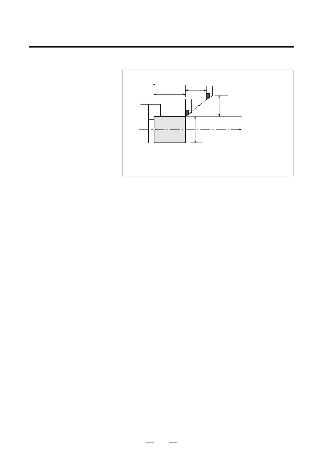
The G00 command moves a tool to the position in the workpiece system
4.1
specified with an absolute or an incremental command at a rapid traverse
POSITIONING
rate.
(G00)
In the absolute command, coordinate value of the end point is
programmed.
In the incremental command the distance the tool moves is programmed.
Format
G00IP_;
IP_:
For an absolute command, the coordinates of an end
position, and for an incremental command, the distance
the tool moves.
Explanations
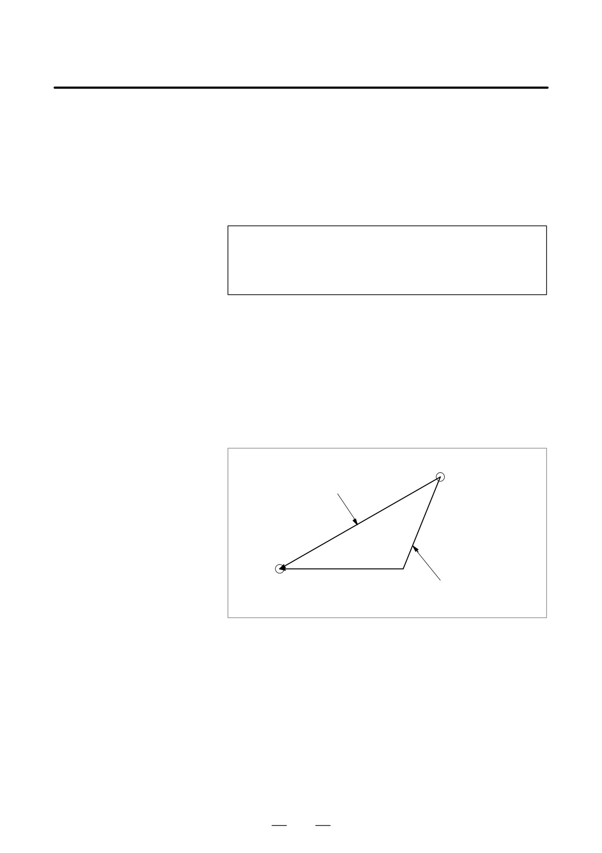
Either of the following tool paths can be selected according to bit 1 (LRP)
of parameter No. 1401.
D Nonlinear interpolation positioning
The tool is positioned with the rapid traverse rate for each axis
separately. The tool path is normally straight.
D Linear interpolation positioning
The tool path is the same as in linear interpolation (G01). The tool is
positioned within the shortest possible time at a speed that is not more
than the rapid traverse rate for each axis.
Start position
Linear interpolation positioning
End position
Non linear interpolation positioning
The rapid traverse rate in the G00 command is set to the parameter
No. 1420 for each axis independently by the machine tool builder. In the
positioning mode actuated by G00, the tool is accelerated to a
predetermined speed at the start of a block and is decelerated at the end
of a block. Execution proceeds to the next block after confirming the
in-position.
“In-position” means that the feed motor is within the specified range.
This range is determined by the machine tool builder by setting to
parameter No. 1826.
43
4. INTERPOLATION FUNCTIONS
PROGRAMMING
B-63524EN/01
Examples
X
30.5
56.0
ÎÎÎ
30.0
ÎÎÎ
Î
Z
φ40.0
< Radius programming >
G00X40.0Z56.0 ; (Absolute command)
or
G00U-60.0W-30.5;(Incremental command)
Restrictions
The rapid traverse rate cannot be specified in the address F.
Even if linear interpolation positioning is specified, nonlinear
interpolation positioning is used in the following cases. Therefore, be
careful to ensure that the tool does not foul the workpiece.
D G28 specifying positioning between the reference and intermediate
positions.
D G53
44
B-63524EN/01
PROGRAMMING
4. INTERPOLATION FUNCTIONS
4.2
Single Direction
Positioning (G60)
General
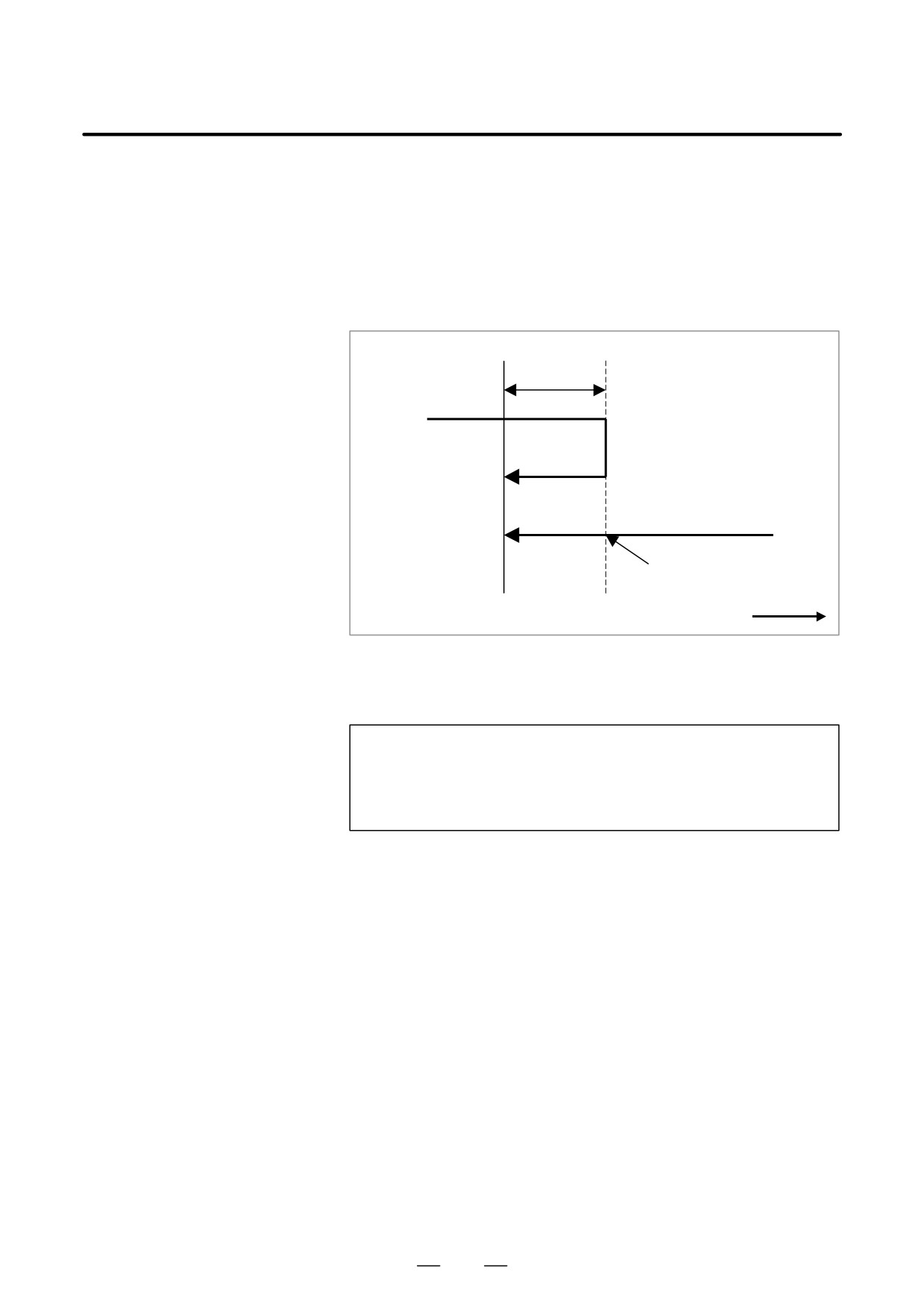
For accurate positioning without play of the machine (backlash), final
positioning from one direction is available.
Overrun
distance
Start
position
Start
position
Temporary
stop
End
+
position
Fig. 4.2 (a) When the positioning direction is minus
Format
G60IP_;
IP_:
For an absolute command, the coordinates of an end
position, and for an incremental command, the distance
the tool moves.
Explanations
An overrun and a positioning direction are set by the parameter
(No.5440). Even when a commanded positioning direction coincides
with that set by the parameter, the tool stops once before the end point.
G60, which is an one-shot G code, can be used as a modal G code in group
01 by setting 1 to the parameter (No. 5431 bit 0 MDL). This setting can
eliminate specifying a G60 command for every block. Other
specifications are the same as those for an one-shot G60 command. When
an one-shot G code is specified in the single direction positioning mode,
the one-shot G command is effective like G codes in group 01.
45
4. INTERPOLATION FUNCTIONS
PROGRAMMING
B-63524EN/01
(example)
When one-shot G60 command are used
When modal G60 command is used
:
:
G90 ;
G90 G60 ;
S.D.P. mode start
G60 X0 Z0 ;
Single
X0 Z0 ;
Single
G60 X100 ;
direction
X100 ;
direction
G60 Z100 ;
positioning
Z100 ;
positioning
G04 X10 ;
G04 X10 ;
G00 X0 Z0 ;
G00 X0 Z0 ;
S.D.P. mode cancel
:
:
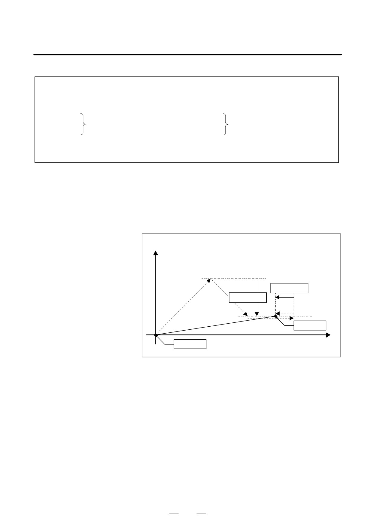
Summary of motion
D When the non-linear
The axes are positioned independently from start point by single direction
positioning is used
positioning as follows.
(parameter No.1401#1
LRP=0)
X
Overrun(Z-axis)
Overrun(X-axis)
End position
Z
Start position
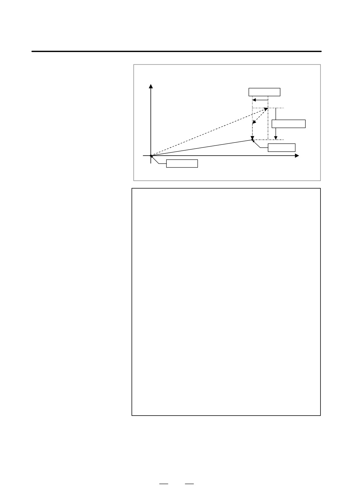
D When the linear
The axes are positioned linear from start position to temporary stop
positioning is used
position or overrun position, and are positioned independently from
(parameter No.1401#1
temporary stop position or overrun position to end position.
LRP=1)
46
B-63524EN/01
PROGRAMMING
4. INTERPOLATION FUNCTIONS
X
Overrun(Z-axis)
Overrun(X-axis)
End position
Z
Start position
NOTE
1
Single direction positioning is not performed in an axis for
which an overrun has not been set by the parameter
(No.5440).
2
When the move distance 0 is commanded, the single
direction positioning is not performed.
3
The mirror image does not influence direction set by the
parameter.
The direction does not change during mirror image.
4
The G-code for single direction positioning is always G60,
if G-code system is A or B or C in all case.
5
The single direction positioning can not be commanded
during the cylindrical interpolation mode (G07.1).
6
The single direction positioning can not be commanded
during the polar coordinate interpolation mode (G12.1).
7
The single direction positioning can not be commanded
during the multiple repetitive cycle (G70-G76).
8
The single direction positioning can not be commanded
during the canned grinding cycle (G71-G74).
9
No single direction positioning is effected in the drilling or
patting axis, during canned cycle for drilling (G83-G89)
and the rigid tapping (G84, G88). But the single direction
positioning is effected in the drilling or patting axis.
10
The single direction positioning can not be commanded
during the canned cycle (G90, G92, G94).
11
During the single direction positioning mode (G60), the
following G-code can not be commanded.
G07.1, G12.1, G70-G76, G90-G94.
47
4. INTERPOLATION FUNCTIONS
PROGRAMMING
B-63524EN/01
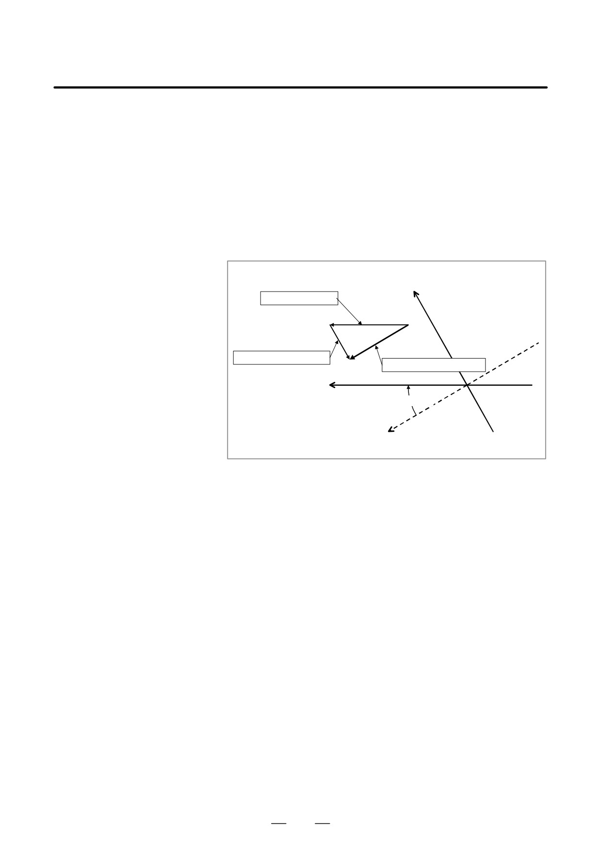
D Notice in case of using
In the angular axis control, the distance traveled along the perpendicular
with the angular axis
axis (X) is corrected by the inclination of the angular axis (Y), and is
control.
determined by the following formula.
Xa = - Yp × tanθ
The direction of ”Xa” is determined by the inclination angle (θ) and the
direction of the motion command to the angular axis (Y). In case the value
of tanθ is plus, the motion command of the angular axis (Y) and the
corrected command of the perpendicular (X) is opposite direction. For
example, if the inclination angle is 30 degree and the motion command
is plus to the angular axis (Y), the corrected command to the perpendicular
axis (X) is minus.
+X(perpendicular axis)
move to plus direction
correct to minus direction : Xa
motion command to plus : Yp
+Y (anglar axis)
coordinate system actually used
θ (inclination angle)
program coordinate system
Therefore positioning direction may be disagree with the actual correct
direction and the positioning direction of the parameter No.5440 in the
perpendicular axis (X) in the single direction positioning with angular
axis control.
For avoiding this disagreement, please set the parameter as follows.
48
B-63524EN/01
PROGRAMMING
4. INTERPOLATION FUNCTIONS
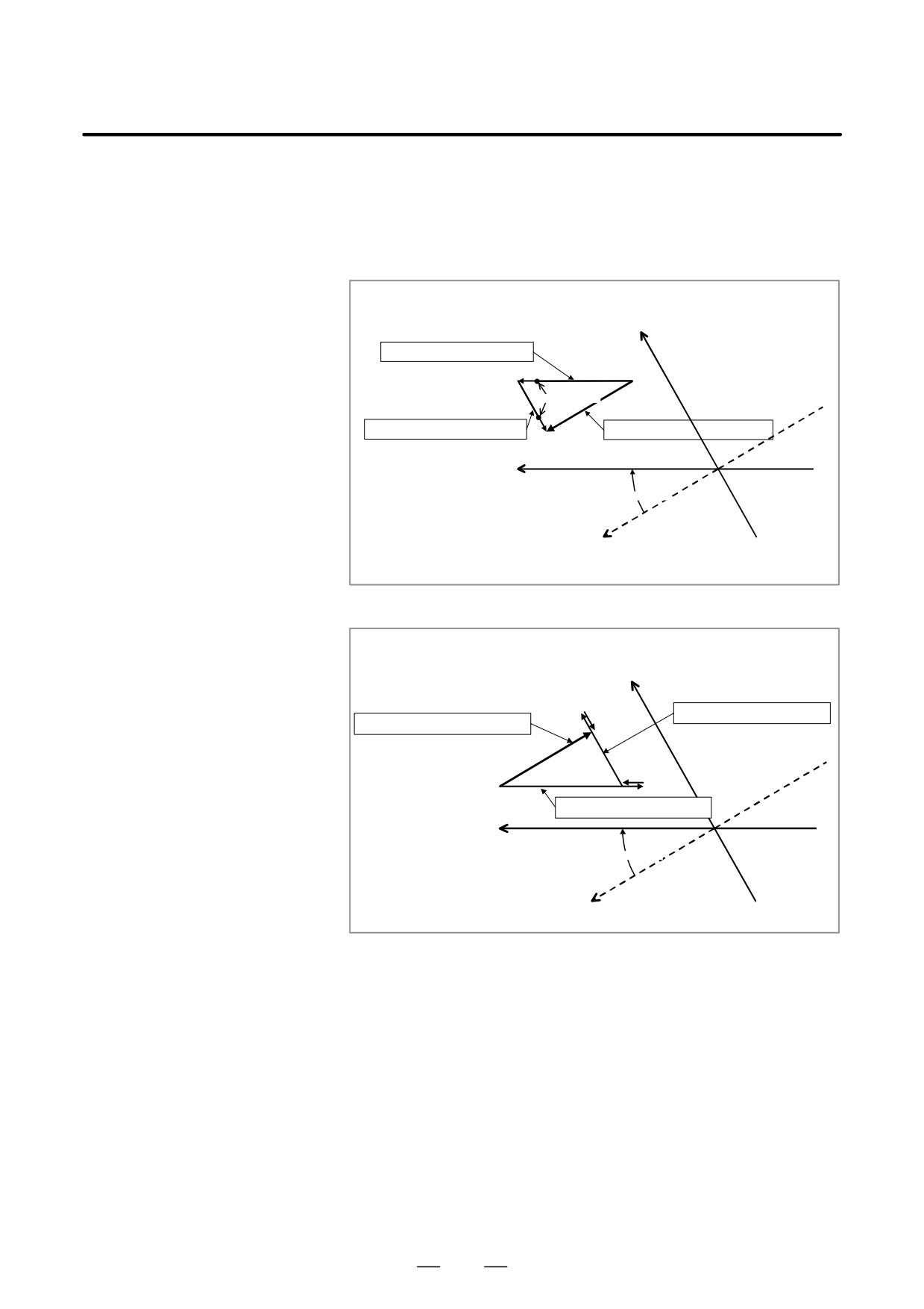
D In case the tan value of
Please set the opposite direction between the angular axis (Y) and the
the inclination angle is
perpendicular axis
(X) into the direction of the single direction
plus. (parameter
positioning. If the positioning direction of the perpendicular axis (X) is
No.8201=1° to 89° or 181°
minus, and the positioning direction of the angular axis (Y) is plus, the
to 269°)
motion of the each axes is as follows.
+X (perpendicular axis)
Y-axis:move to plus direction
temporary stop
X-axis:correct to minus direction
motion command to plus direction
+Y (angular axis)
coordinate system actually used
θ (inclination angle)
program coordinate system
Motion command to plus direction
+X (perpendicular axis)
X-axis:correct to plus direction
motion command to minus direction
Y-axis:move to minus direction
+Y (angular axis)
coordinate system actually used
θ (inclination angle)
program coordinate system
Motion command to minus direction
49
4. INTERPOLATION FUNCTIONS
PROGRAMMING
B-63524EN/01
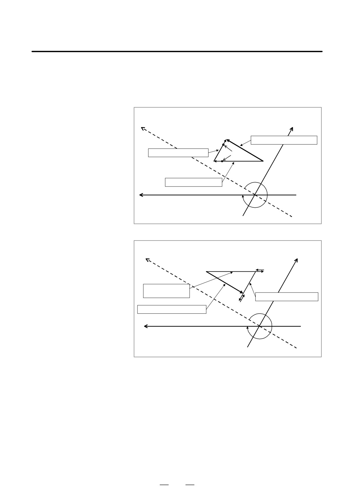
D In case the tan value of
Please set the same direction between the angular axis (Y) and the
the inclination angle is
perpendicular axis
(X) into the direction of the single direction
minus. (parameter
positioning. If the positioning direction of the perpendicular axis (X) is
No.8201=91° to 179° or
plus, and the positioning direction of the angular axis (Y) is plus, the
271° to 359°
motion of the each axes is as follows.
program coordinate system
+X (perpendicular axis)
motion command to plus direction
X-axis:correct to plus direction
temporary stop
Y-axis:mov to plus direction
θ (inclination angle)
+Y (angular axis)
coordinate system actually used
Motion command to plus direction
program coordinate system
+X (perpendicular axis)
Y-axis:move to minus
direction
X-axis:correct to minus direction
motion command to minus direction
θ (inclination angle)
+Y (angluar axis)
coordinate system actually used
Motion command to minus direction
50
B-63524EN/01
PROGRAMMING
4. INTERPOLATION FUNCTIONS
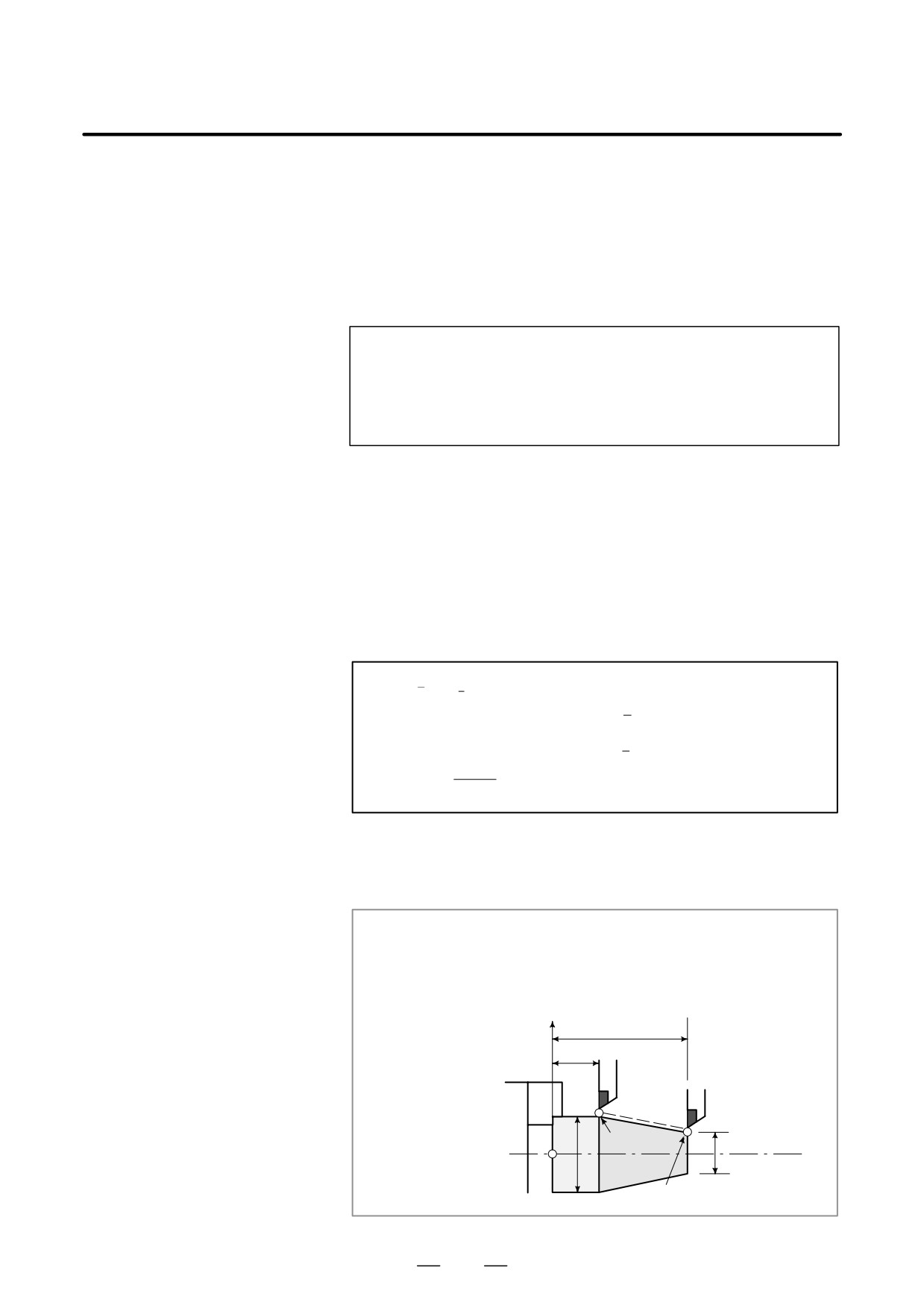
Tools can move along a line.
4.3
LINEAR
INTERPOLATION
(G01)
Format
G01 IP_F_;
IP_:
For an absolute command, the coordinates of an end
point , and for an incremental command, the distance
the tool moves.
F_:
Speed of tool feed (Feedrate)
Explanations
A tools move along a line to the specified position at the feedrate
specified in F.
The feedrate specified in F is effective until a new value is specified. It
need not be specified for each block.
The feedrate commanded by the F code is measured along the tool path.
If the F code is not commanded, the feedrate is regarded as zero.
For feed-per-minute mode under 2-axis simultaneous control, the
feedrate for a movement along each axis as follows :
G01ααββ Ff ;
Feed rate of α axis direction : Fa +a
f
L
b
Feed rate of β axis direction :
Fb +
f
L
L + a2 ) b2Ǹ
Examples
D Linear interpolation
< Diameter programming >
G01X40.0Z20.1F20 ; (Absolute command)
or
G01U20.0W-25.9F20 ; (Incremental command)
X
46.0
20.1
ÎÎ
ÎÎ
ÎÎ
End point
φ20.0
Z
φ40.0
Start point
51
4. INTERPOLATION FUNCTIONS
PROGRAMMING
B-63524EN/01
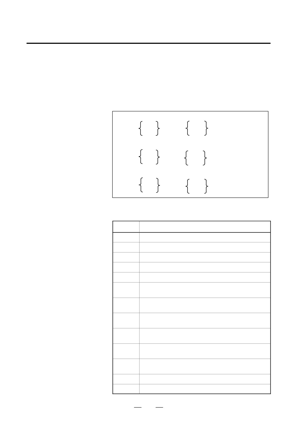
The command below will move a tool along a circular arc.
4.4
CIRCULAR
INTERPOLATION
(G02, G03)
Format
Arc in the XpYp plane
G17
G02
I_J_
Xp_Yp_
F_
G03
R_
Arc in the ZpXp plane
G02
I_K_
G18
Xp_Zp_
F_
G03
R_
Arc in the YpZp plane
G02
Yp_Zp_
J_K_ F_
G19
G03
R_
Table 4.4 Description of the Command Format
Command
Description
G17
Specification of arc on XpYp plane
G18
Specification of arc on ZpXp plane
G19
Specification of arc on YpZp plane
G02
Circular Interpolation Clockwise direction (CW)
G03
Circular Interpolation Counterclockwise direction (CCW)
Xp_
Command values of X axis or its parallel axis
(set by parameter No. 1022)
Yp_
Command values of Y axis or its parallel axis
(set by parameter No. 1022)
Zp_
Command values of Z axis or its parallel axis
(set by parameter No. 1022)
I_
Xp axis distance from the start point to the center of an arc with
sign, radius value
J_
Yp axis distance from the start point to the center of an arc with
sign, radius value
k_
Zp axis distance from the start point to the center of an arc with
sign, radius value
R_
Arc radius with no sign (always with radius value)
F_
Feedrate along the arc
52
B-63524EN/01
PROGRAMMING
4. INTERPOLATION FUNCTIONS
NOTE
The U-, V-, and W-axes (parallel with the basic axis) can
be used with G-codes B and C.
Explanations
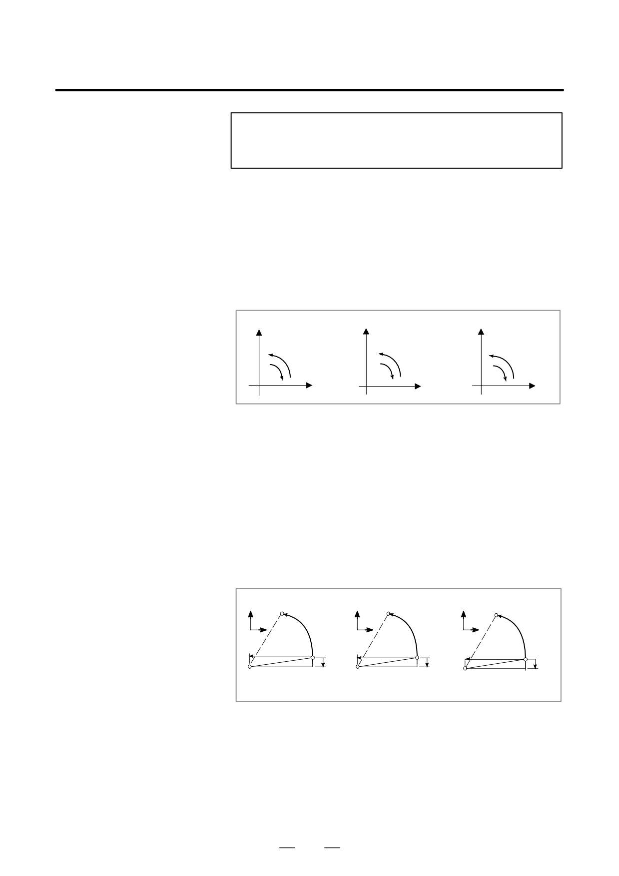
D Direction of the circular
“Clockwise” (G02) and “counterclockwise” (G03) on the XpYp plane
interpolation
(ZpXp plane or YpZp plane) are defined when the XpYp plane is viewed
in the positive-to-negative direction of the Zp axis (Yp axis or Xp axis,
respectively) in the Cartesian coordinate system. See the figure below.
Yp
Xp
Zp
G03
G03
G03
G02
G02
G02
Xp
Zp
Yp
G17
G18
G19
D Distance moved on an
The end point of an arc is specified by address Xp, Yp or Zp, and is
arc
expressed as an absolute or incremental value according to G90 or G91.
For the incremental value, the distance of the end point which is viewed
from the start point of the arc is specified.
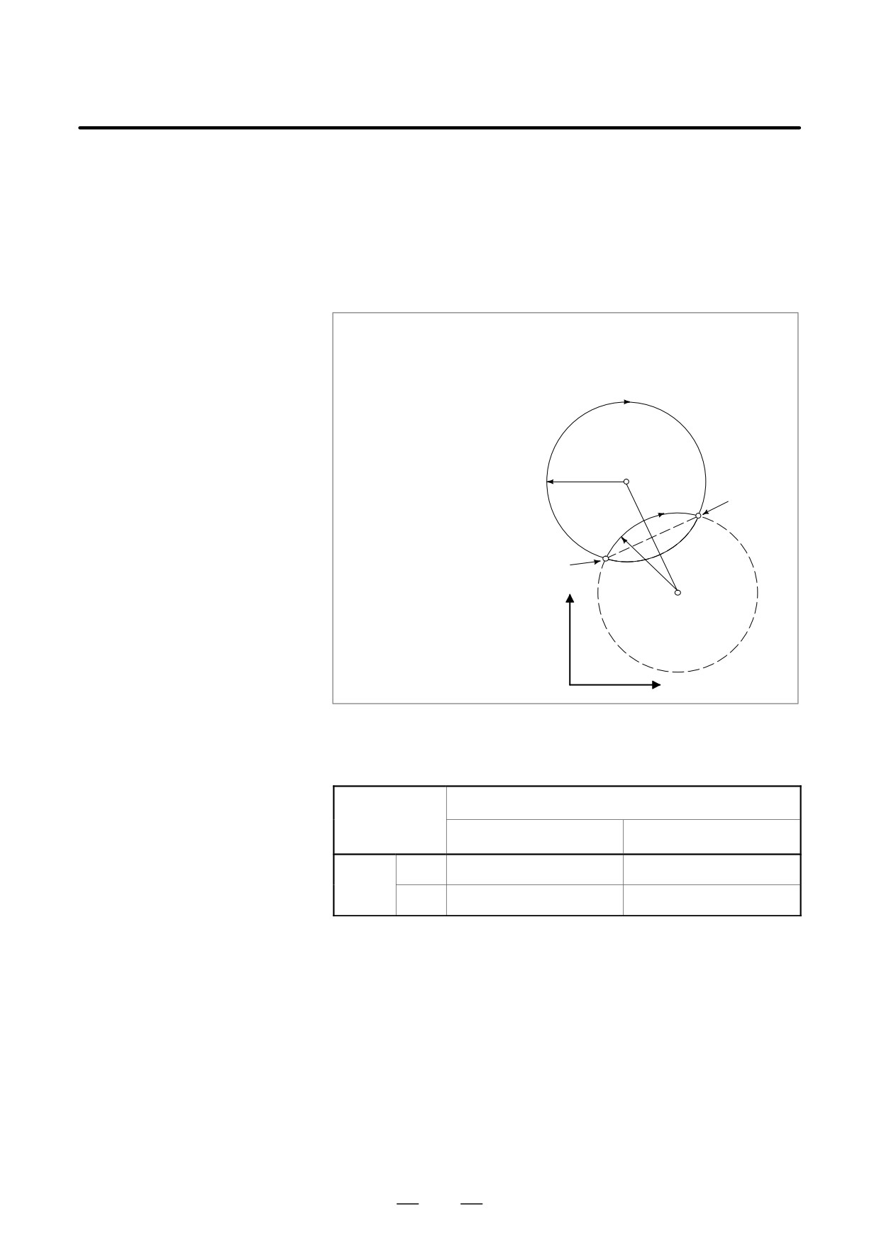
D Distance from the start
The arc center is specified by addresses I, J, and K for the Xp, Yp, and Zp
point to the center of arc
axes, respectively. The numerical value following I, J, or K, however, is
a vector component in which the arc center is seen from the start point,
and is always specified as an incremental value irrespective of G90 and
G91, as shown below.
I, J, and K must be signed according to the direction.
End point (x,y)
End point (z,x)
End point (y,z)
y
x
z
x
Start
z
y
Start
j
Start
i
k
point
point
point
j
i
k
Center
Center
Center
I0, J0, and K0 can be omitted.
If the difference between the radius at the start point and that at the end
point exceeds the value in a parameter (No. 3410), an P/S alarm (No. 020)
occurs.
When Xp, Yp , and Zp are omitted (the end point is the same as the start
D Full-circle programming
point) and the center is specified with I, J, and K, a 360° arc (circle) is
specified.
53
4. INTERPOLATION FUNCTIONS
PROGRAMMING
B-63524EN/01
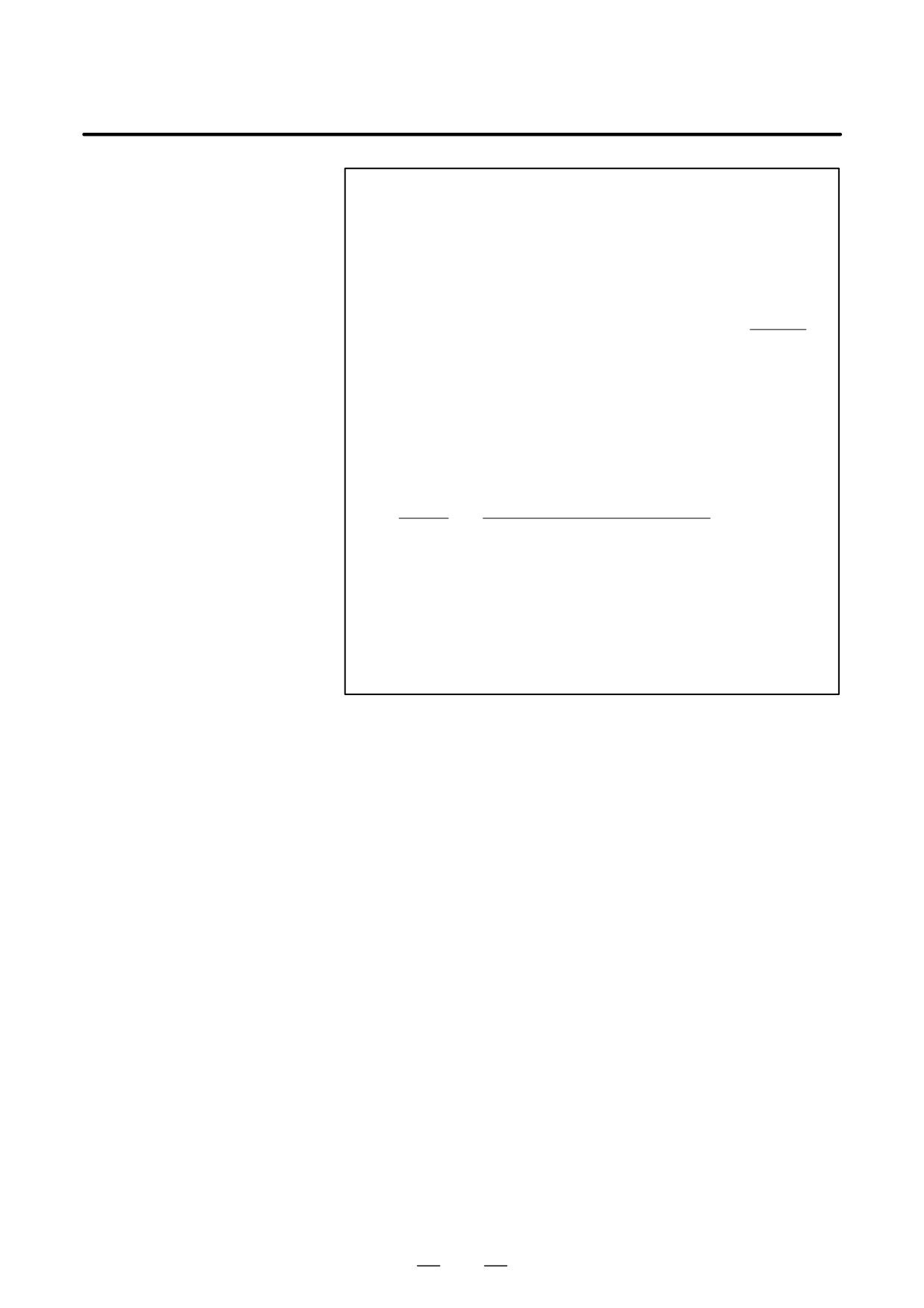
D Arc radius
The distance between an arc and the center of a circle that contains the arc
can be specified using the radius, R, of the circle instead of I, J, and K.
In this case, one arc is less than 180°, and the other is more than 180° are
considered. An arc with a sector angle of 180° or wider cannot be
specified. If Xp, Yp, and Zp are all omitted, if the end point is located at
the same position as the start point and when R is used, an arc of 0° is
programmed
G02R ; (The cutter does not move.)
For arc (1) (less than 180°)
G02 W60.0 U10.0 R50.0 F300.0 ;
For arc (2) (greater than 180°)
An arc with a sector angle of 180°
or wider cannot be specified
within a single block.
(2)
r=50mm
End point
(1)
Start point
r=50mm
X
Z
D Arc radius R with nine
When the option for specifying arc radius R with nine digits is selected,
digits (option)
the valid radius range for circular interpolation is expanded as follows:
Input increments
Metric input
Inch input
Incre-
IS-B
0.001 to 999999.999 mm
0.0001 to 99999.9999 inch
ment
system
IS-C
0.0001 to 99999.9999 mm
0.00001 to 9999.99999 inch
54
B-63524EN/01
PROGRAMMING
4. INTERPOLATION FUNCTIONS
NOTE
When using the nine-digit arc radius R function, note the
following points.
1
Specifying an arc center with addresses I, K, and J
When the distance from the arc start point to the arc center
is specified with addresses I, K, and J, a P/S alarm (No.
5059) is issued if:
Ǹ
Maximum value which can be specified t I2 ) K2
Example: When IS-B and metric input are selected,
issuing the following command
(radius
specification) will result in a P/S alarm
(No.
5059):
G50 X0 Z0;
G18G02X11.250 Z10. I-800000.000 K900000.000 F5.0;
MǸ
I2 ) K2
+ (* 800000.000)2 ) 900000.0002Ǹ
+ 1204159.458
u 999999.999
2
Tool nose radius compensation
In tool nose radius compensation mode, a P/S alarm (No.
5059) is issued if the distance from the tool nose radius
center to the arc center exceeds the maximum value which
can be specified.
D Feedrate
The feedrate in circular interpolation is equal to the feed rate specified by
the F code, and the feedrate along the arc (the tangential feedrate of the
arc) is controlled to be the specified feedrate.
The error between the specified feedrate and the actual tool feedrate is
±2% or less. However, this feed rate is measured along the arc after the
tool nose radius compensation is applied.
Restrictions
D Simultaneously
If I, J, K, and R addresses are specified simultaneously, the arc specified
specifying R with I, J,
by address R takes precedence and the other are ignored.
and K
D Specifying an axis that is
If an axis not contained in the specified plane is commanded, an alarm
not contained in the
is displayed.
specified plane
For example, when a ZX plane is specified in G-code B or C, specifying
the X-axis or U-axis (parallel to the X-axis) causes P/S alarm No. 028
to be generated.
D Difference in the radius
If the difference in the radius between the start and end points of the arc
between the start and
exceeds the value specified in parameter No. 3410, P/S alarm No. 020 is
end points
generated.
If the end point is not on the arc, the tool moves in a straight line along
one of the axes after reaching the end point.
55
4. INTERPOLATION FUNCTIONS
PROGRAMMING
B-63524EN/01
D Specifying a semicircle
If an arc having a central angle approaching 180° is specified with R, the
with R
calculation of the center coordinates may produce an error. In such a case,
specify the center of the arc with I, J, and K.
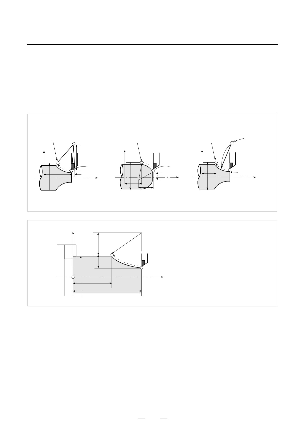
Examples
D Command of circular
interpolation X, Z
G02X_Z_I_K_F_;
G03X_Z_I_K_F_;
G02X_Z_R_F_;
Center of arc
End point
End point
End point
Center of arc
X-axis
X-axis
X-axis
(Diameter
R
(Diameter
(Diameter
programming)
programming)
programming)
Start point
Start point
X
X
X
Start point
Z
K
Z
Z-axis
Z
Z-axis
Z-axis
K
(Absolute programming)
(Absolute programming)
(Absolute programming)
X
R25.0
(Diameter programming)
15.0
G02X50.0Z30.0I25.0F0.3; or
ÎÎ
G02U20.0W-020.0I25.0F0.3; or
G02X50.0Z30.0R25.0F0.3 or
ÎÎ
10.0
G02U20.0W-20.0R25.F0.3;
φ50.0
Z
30.0
50.0
56
B-63524EN/01
PROGRAMMING
4. INTERPOLATION FUNCTIONS
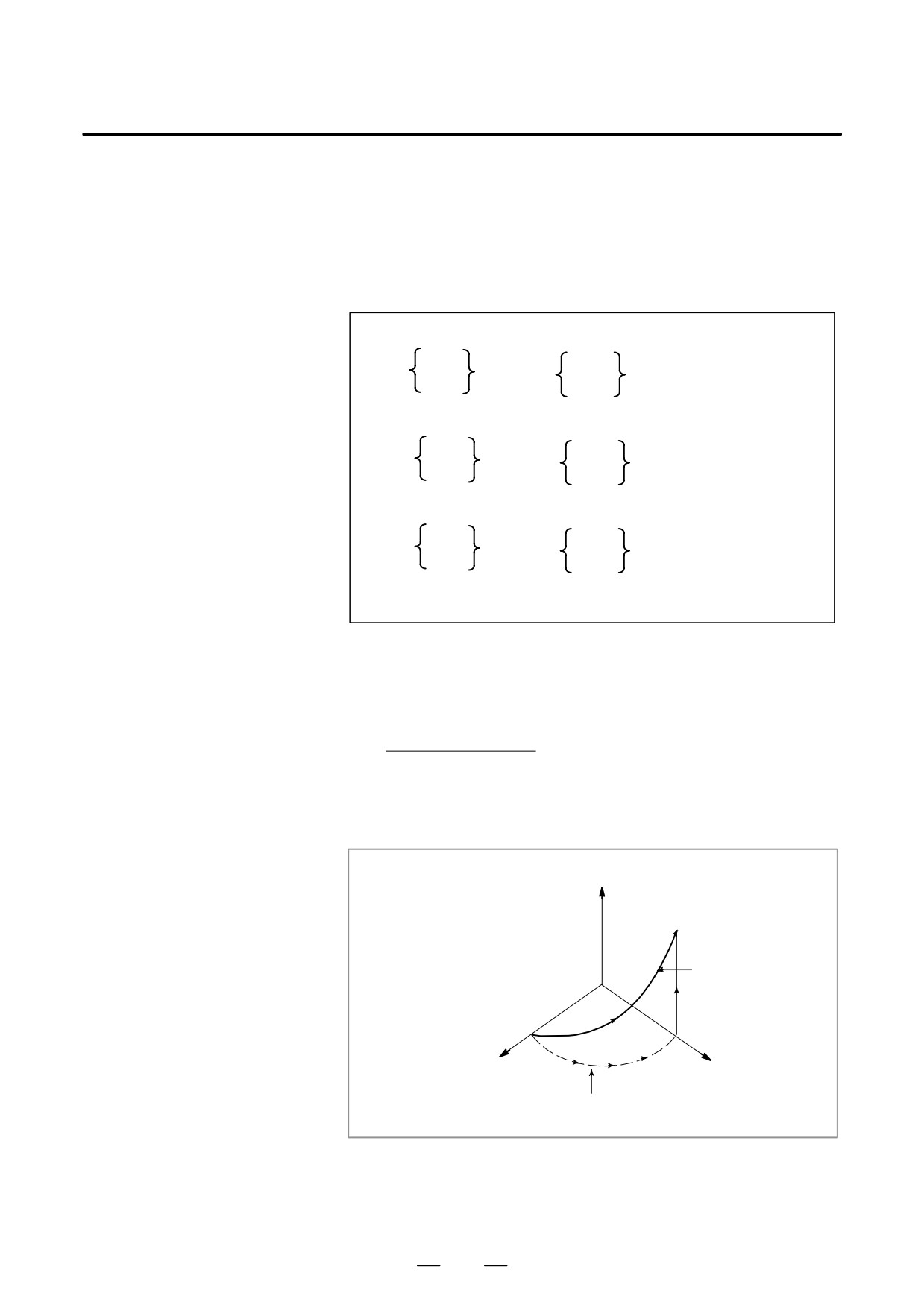
Helical interpolation which moved helically is enabled by specifying up
4.5
to two other axes which move synchronously with the circular
HELICAL
interpolation by circular commands.
INTERPOLATION
(G02, G03)
Format
Synchronously with arc of XpYp plane
G02
G17
I_J_
Xp_Yp_
a_(b_)F_;
G03
R_
Synchronously with arc of ZpXp plane
G02
G18
I_K_
Xp_Zp_
a_(b_)F_;
G03
R_
Synchronously with arc of YpZp plane
G02
J_K_
G19
Yp_Zp_
a_(b_)F_;
G03
R_
a, b : Any one axis where circular interpolation is not applied.
Up to two other axes can be specified.
Explanations
The command method is to simply or secondary add a move command
axis which is not circular interpolation axes. An F command specifies a
feed rate along a circular arc. Therefore, the feed rate of the linear axis
is as follows:
Length of linear axis
F×
Length of circular arc
Determine the feed rate so the linear axis feed rate does not exceed any
of the various limit values. Bit 0 (HFC) of parameter No. 1404 can be used
to prevent the linear axis feedrate from exceeding various limit values.
Z
Tool path
X
Y
The feedrate along the circumference of two cir-
cular interpolated axes is the specified feedrate.
Limitations
D Tool nose radius compensation is applied only for a circular arc.
D Tool offset and tool length compensation cannot be used in a block in
which a helical interpolation is commanded.
57
4. INTERPOLATION FUNCTIONS
PROGRAMMING
B-63524EN/01
Polar coordinate interpolation is a function that exercises contour control
4.6
in converting a command programmed in a Cartesian coordinate system
POLAR COORDINATE
to the movement of a linear axis (movement of a tool) and the movement
INTERPOLATION
of a rotary axis (rotation of a workpiece). This method is useful in cutting
(G12.1, G13.1)
a front surface and grinding a cam shaft on a lathe.
Format
G12.1 ;
Starts polar coordinate interpolation mode (enables
D Specify G12.1 and G13.1
polar coordinate interpolation)
in Separate Blocks.
Specify linear or circular interpolation using coordinates
in a Cartesian coordinate system consisting of a linear
axis and rotary axis (virtual axis).
G13.1 ;
Polar coordinate interpolation mode is cancelled (for
not performing polar coordinate interpolation)
G112 and G113 can be used in place of G12.1 and G13.1,
respectively.
Explanations
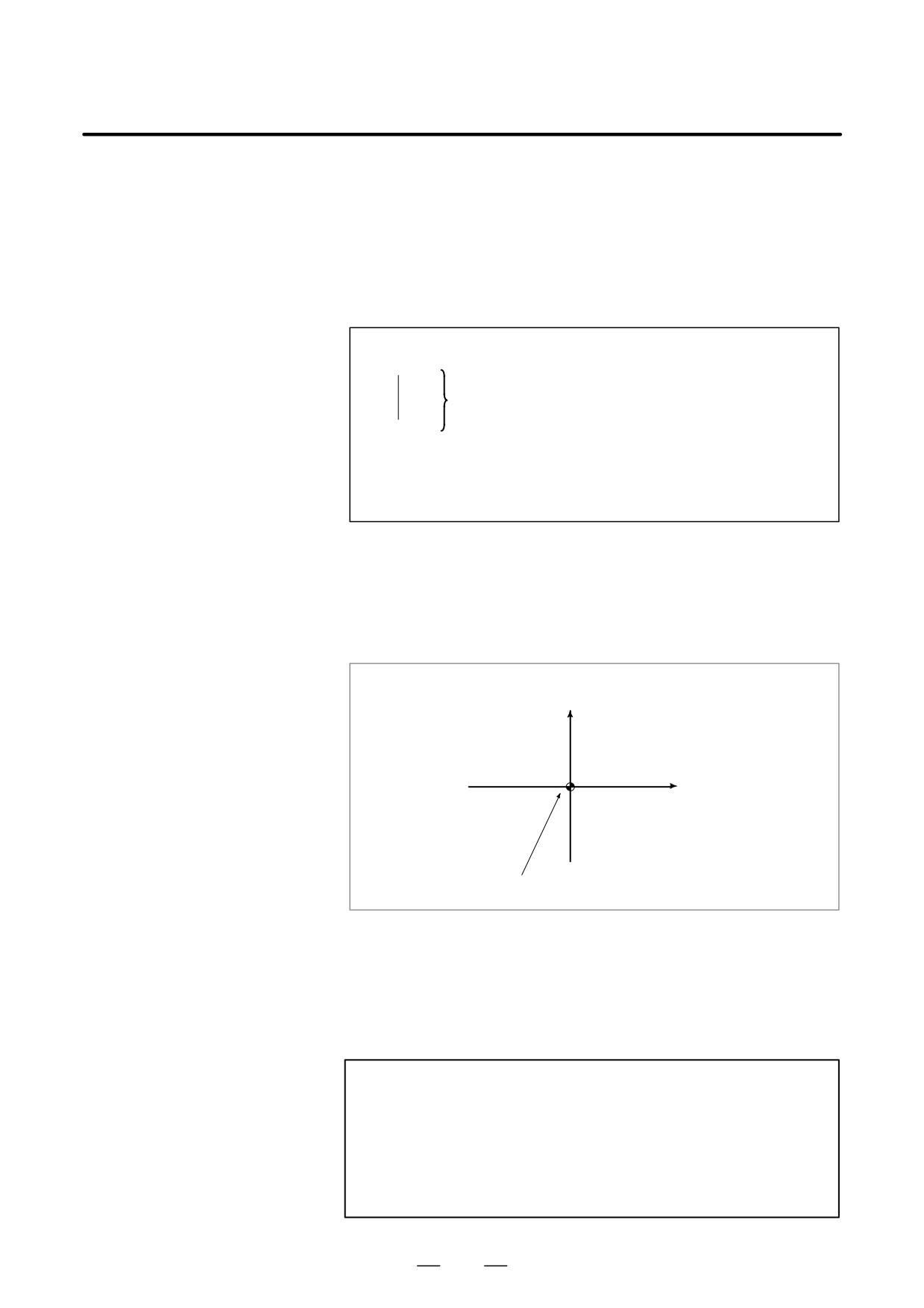
D Polar coordinate
G12.1 starts the polar coordinate interpolation mode and selects a polar
interpolation plane
coordinate interpolation plane
(Fig.
4.6
(a)).
Polar coordinate
interpolation is performed on this plane.
Rotary axis (virtual axis)
(unit:mm or inch)
Linear axis
(unit:mm or inch)
Origin of the workpiece coordinate system
Fig. 4.6 (a) Polar coordinate interpolation plane.
When the power is turned on or the system is reset, polar coordinate
interpolation is canceled (G13.1).
The linear and rotation axes for polar coordinate interpolation must be set
in parameters (No. 5460 and 5461) beforehand.
CAUTION
The plane used before G12.1 is specified (plane selected
by G17, G18, or G19) is canceled. It is restored when G13.1
(canceling polar coordinate interpolation) is specified.
When the system is reset, polar coordinate interpolation is
canceled and the plane specified by G17, G18, or G19 is
used.
58
B-63524EN/01
PROGRAMMING
4. INTERPOLATION FUNCTIONS
D Distance moved and
In the polar coordinate interpolation mode, program commands are
feedrate for polar
specified with Cartesian coordinates on the polar coordinate interpolation
coordinate interpolation
plane. The axis address for the rotation axis is used as the axis address
for the second axis (virtual axis) in the plane. Whether a diameter or
The unit for coordinates
radius is specified for the first axis in the plane is the same as for the
on the hypothetical axis
rotation axis regardless of the specification for the first axis in the plane.
is the same as the unit for
The virtual axis is at coordinate 0 immediately after G12.1 is specified.
the linear axis (mm/inch)
Polar interpolation is started assuming the angle of 0 for the position of
the tool when G12.1 is specified.
The unit for the feedrate
Specify the feedrate as a speed (relative speed between the workpiece and
is mm/min or inch/min
tool) tangential to the polar coordinate interpolation plane (Cartesian
coordinate system) using F.
D G codes which can be
G01
. . . . . . . . . . . . Linear interpolation
specified in the polar
G02, G03
Circular interpolation
coordinate interpolation
G04
Dwell
mode
G40, G41, G42 .
Tool nose radius compensation
(Polar coordinate interpolation is applied to the
path after cutter compensation.)
G65, G66, G67
Custom macro command
G98, G99
Feed per minute, feed per revolution
D Circular interpolation in
The addresses for specifying the radius of an arc for circular interpolation
the polar coordinate
(G02 or G03) in the polar coordinate interpolation plane depend on the
plane
first axis in the plane (linear axis).
D I and J in the Xp-Yp plane when the linear axis is the X-axis or an axis
parallel to the X-axis.
D J and K in the Yp-Zp plane when the linear axis is Y-axis or an axis
parallel to the Y-axis.
D K and I in the Zp-Xp plane when the linear axis is the Z-axis or an axis
parallel to the Z-axis.
The radius of an arc can be specified also with an R command.
NOTE
The U-, V-, and W-axes (parallel with the basic axis) can
be used with G-codes B and C.
D Movement along axes
The tool moves along such axes normally, independent of polar
not in the polar
coordinate interpolation.
coordinate interpolation
plane in the polar
coordinate interpolation
mode
D Current position display
Actual coordinates are displayed. However, the remaining distance to
in the polar coordinate
move in a block is displayed based on the coordinates in the polar
interpolation mode
coordinate interpolation plane (Cartesian coordinates).
59
4. INTERPOLATION FUNCTIONS
PROGRAMMING
B-63524EN/01
Restrictions
D Coordinate system for the
Before G12.1 is specified, a workpiece coordinate system) where the
polar coordinate
center of the rotary axis is the origin of the coordinate system must be set.
interpolation
In the G12.1 mode, the coordinate system must not be changed (G92,
G52, G53, relative coordinate reset, G54 through G59, etc.).
D Tool nose radius
The polar coordinate interpolation mode cannot be started or terminated
compensation command
(G12.1 or G13.1) in the tool nose radius compensation mode (G41 or
G42). G12.1 or G13.1 must be specified in the tool nose radius
compensation canceled mode (G40).
D Program restart
For a block in the G12.1 mode, the program cannot be restarted.
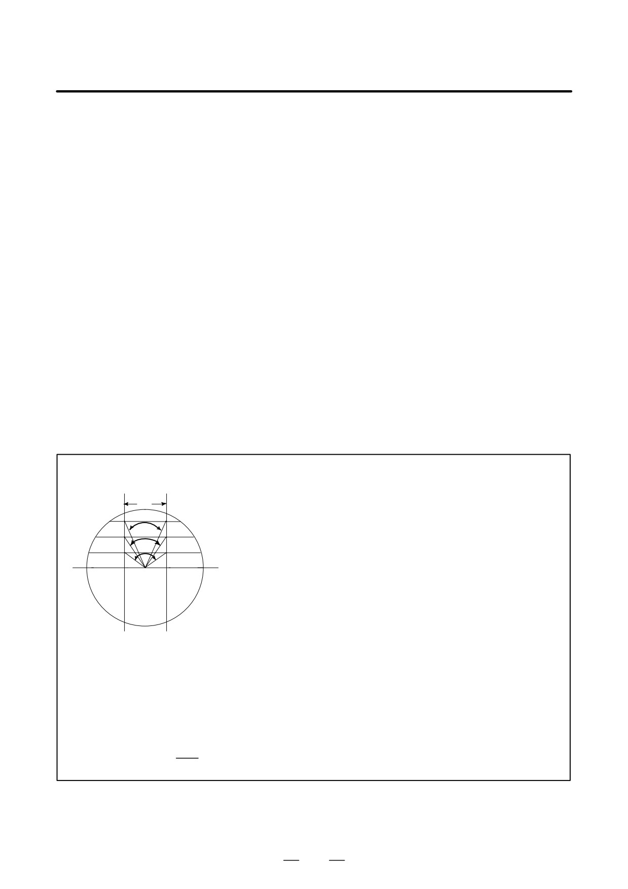
D Cutting feedrate for the
Polar coordinate interpolation converts the tool movement for a figure
rotation axis
programmed in a Cartesian coordinate system to the tool movement in the
rotation axis (C-axis) and the linear axis (X-axis). When the tool moves
closer to the center of the workpiece, the C-axis component of the
feedrate becomes larger and may exceed the maximum cutting feedrate
for the C-axis (set in parameter (No. 1422)), causing an alarm (see the
figure below). To prevent the C-axis component from exceeding the
maximum cutting feedrate for the C-axis, reduce the feedrate specified
with address F or create a program so that the tool (center of the tool when
tool nose radius compensation is applied) does not move close to the
center of the workpiece.
WARNING
Consider lines L1, L2, and L3. ∆X is the distance the tool moves
per time unit at the feedrate specified with address F in the
∆
X
Cartesian coordinate system. As the tool moves from L1 to L2 to
θ1
L1
L3, the angle at which the tool moves per time unit corresponding
θ2
L2
to ∆X in the Cartesian coordinate system increases fromθ1 toθ 2
θ3
to θ3.
L3
In other words, the C-axis component of the feedrate becomes
larger as the tool moves closer to the center of the workpiece.
The C component of the feedrate may exceed the maximum
cutting feedrate for the C-axis because the tool movement in the
Cartesian coordinate system has been converted to the tool
movement for the C-axis and the X-axis.
L : Distance (in mm) between the tool center and workpiece center when the tool center is the
nearest to the workpiece center
R :Maximum cutting feedrate (deg/min) of the C axis
Then, a speed specifiable with address F in polar coordinate interpolation can be given by the
formula below. Specify a speed allowed by the formula. The formula provides a theoretical
value; in practice, a value slightly smaller than a theoretical value may need to be used due to
a calculation error.
π
F < L × R ×
(mm/min)
180
D Diameter and radius
Even when diameter programming is used for the linear axis (X-axis),
programming
radius programming is applied to the rotary axis (C-axis).
60
B-63524EN/01
PROGRAMMING
4. INTERPOLATION FUNCTIONS
Examples
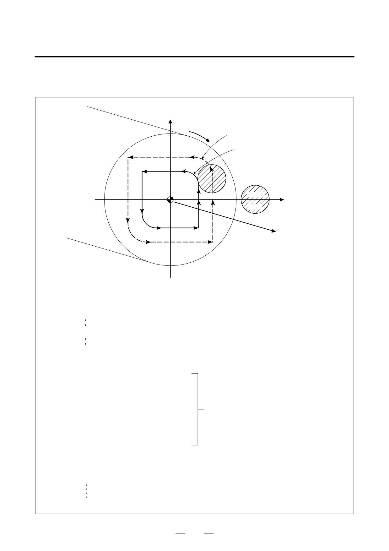
Example of Polar Coordinate Interpolation Program Based on X Axis
(Linear Axis) and C Axis (Rotary Axis)
C′ (hypothetical axis)
C axis
Path after tool nose radius compensation
Program path
N204
N203
N205
N202
N201
N200
X axis
Tool
N208
N206
N207
Z axis
X axis is by diameter programming, C axis is by radius programming.
O0001 ;
N010 T0101
N0100 G00 X120.0 C0 Z _ ;
Positioning to start position
N0200 G12.1 ;
Start of polar coordinate interpolation
N0201 G42 G01 X40.0 F _ ;
N0202 C10.0 ;
N0203 G03 X20.0 C20.0 R10.0 ;
N0204 G01 X-40.0 ;
Geometry program
N0205 C-10.0 ;
(program based on cartesian coordinates on
N0206 G03 X-20.0 C-20.0 I10.0 J0 ;
X-C′ plane)
N0207 G01 X40.0 ;
N0208 C0 ;
N0209 G40 X120.0 ;
N0210 G13.1 ;
Cancellation of polar coordinate interpolation
N0300 Z __ ;
N0400 X __C __ ;
N0900M30 ;
61
4. INTERPOLATION FUNCTIONS
PROGRAMMING
B-63524EN/01
The amount of travel of a rotary axis specified by an angle is once
4.7
internally converted to a distance of a linear axis along the outer surface
CYLINDRICAL
so that linear interpolation or circular interpolation can be performed with
INTERPOLATION
another axis. After interpolation, such a distance is converted back to the
(G07.1)
amount of travel of the rotary axis.
The cylindrical interpolation function allows the side of a cylinder to be
developed for programming. So programs such as a program for
cylindrical cam grooving can be created very easily.
Format
G07.1 IP r ; Starts the cylindrical interpolation mode
:
(enables cylindrical interpolation).
:
:
G07.1 IP 0 ; The cylindrical interpolation mode is cancelled.
IP : An address for the rotation axis
r : Radius value of the cylinder
Specify G07.1 IP r ; and G07.1 IP 0; in separate blocks.
G107 can be used instead of G07.1.
Explanations
D Plane selection
Use parameter No. 1002 to specify whether the rotation axis is the X-, Y-,
(G17, G18, G19)
or Z-axis, or an axis parallel to one of these axes. Specify the G code to
select a plane for which the rotation axis is the specified linear axis.
For example, when the rotation axis is an axis parallel to the X-axis, G17
must specify an Xp-Yp plane, which is a plane defined by the rotation axis
and the Y-axis or an axis parallel to the Y-axis.
Only one rotation axis can be set for cylindrical interpolation.
NOTE
The U-, V-, and W-axes (parallel with the basic axis) can
be used with G-codes B and C.
D Feedrate
A feedrate specified in the cylindrical interpolation mode is a speed on the
developed cylindrical surface.
62
B-63524EN/01
PROGRAMMING
4. INTERPOLATION FUNCTIONS
D Circular interpolation
In the cylindrical interpolation mode, circular interpolation is possible
(G02,G03)
with the rotation axis and another linear axis. Radius R is used in
commands in the same way as described in Section 4.4.
The unit for a radius is not degrees but millimeters (for metric input) or
inches (for inch input).
< Example Circular interpolation between the Z axis and C axis >
For the C axis of parameter No. 1022, 5 (axis parallel with the X axis)
is to be set. In this case, the command for circular interpolation is
G18 Z__C__;
G02 (G03) Z__C__R__;
For the C axis of parameter No. 1022, 6 (axis parallel with the Y axis)
may be specified instead. In this case, however, the command for
circular interpolation is
G19 C__Z__;
G02 (G03) Z__C__R__;
D Tool nose radius
To perform tool nose radius compensation in the cylindrical interpolation
compensation
mode, cancel any ongoing tool nose radius compensation mode before
entering the cylindrical interpolation mode. Then, start and terminate tool
nose radius compensation within the cylindrical interpolation mode.
D Cylindrical interpolation
In the cylindrical interpolation mode, the amount of travel of a rotary axis
accuracy
specified by an angle is once internally converted to a distance of a linear
axis on the outer surface so that linear interpolation or circular
interpolation can be performed with another axis. After interpolation,
such a distance is converted back to an angle. For this conversion, the
amount of travel is rounded to a least input increment.
So when the radius of a cylinder is small, the actual amount of travel can
differ from a specified amount of travel. Note, however, that such an error
is not accumulative.
If manual operation is performed in the cylindrical interpolation mode
with manual absolute on, an error can occur for the reason described
above.
MOTION REV
2×2πR
The actual amount
Specified value
=
of travel
2×2πR
MOTION REV
MOTION REV : The amount of travel per rotation of the rotation axis (Set-
ting value of parameter No. 1260)
R
:
Workpiece radius
: Rounded to the least input increment
Restrictions
D Arc radius specification
In the cylindrical interpolation mode, an arc radius cannot be specified
in the cylindrical
with word address I, J, or K.
interpolation mode
D Circular interpolation
If the cylindrical interpolation mode is started when tool nose radius
and tool nose radius
compensation is already applied, circular interpolation is not correctly
compensation
performed in the cylindrical interpolation mode.
63
4. INTERPOLATION FUNCTIONS
PROGRAMMING
B-63524EN/01
D Positioning
In the cylindrical interpolation mode, positioning operations (including
those that produce rapid traverse cycles such as G28, G80 through G89)
cannot be specified. Before positioning can be specified, the cylindrical
interpolation mode must be cancelled. Cylindrical interpolation (G07.1)
cannot be performed in the positioning mode (G00).
D Coordinate system
In the cylindrical interpolation mode, a workpiece coordinate system G50
setting
cannot be specified.
D Cylindrical interpolation
In the cylindrical interpolation mode, the cylindrical interpolation mode
mode setting
cannot be reset. The cylindrical interpolation mode must be cancelled
before the cylindrical interpolation mode can be reset.
D Canned cycle for drilling
Canned cycles for drilling, G81 to G89, cannot be specified during
during cylindrical
cylindrical interpolation mode.
interpolation mode
D Mirror Image for Double
Mirror image for double turret, G68 and G69, cannot be specified during
Turret
cylindrical interpolation mode.
64
B-63524EN/01
PROGRAMMING
4. INTERPOLATION FUNCTIONS
Examples
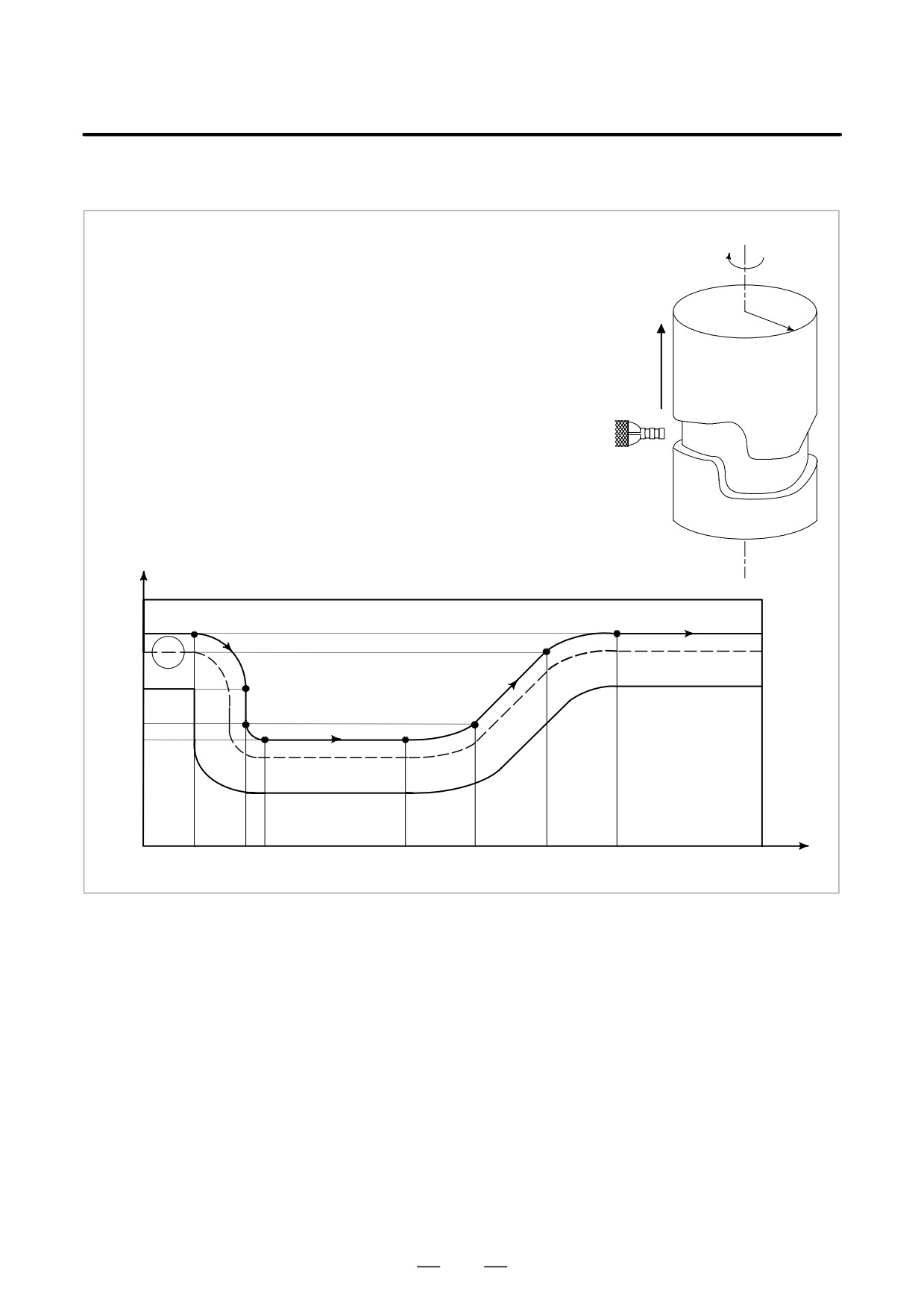
Example of a Cylindrical Interpolation Program
C
O0001 (CYLINDRICAL INTERPOLATION );
N01 G00 Z100.0 C0 ;
N02 G01 G18 W0 H0 ;
Z
R
N03 G07.1 H57299 ;
N04 G01 G42 Z120.0 D01 F250 ;
N05 C30.0 ;
N06 G03 Z90.0 C60.0 R30.0 ;
N07 G01 Z70.0 ;
N08 G02 Z60.0 C70.0 R10.0 ;
N09 G01 C150.0 ;
N10 G02 Z70.0 C190.0 R75.0 ;
N11 G01 Z110.0 C230.0 ;
N12 G03 Z120.0 C270.0 R75.0 ;
N13 G01 C360.0 ;
N14 G40 Z100.0 ;
N15 G07.1 C0 ;
N16 M30 ;
Z
mm
N0
N12
N13
120
5
110
N06
N11
90
N07
70
N08
N09
N10
60
C
0
30
60 70
150
190
230
270
360
deg
65
4. INTERPOLATION FUNCTIONS
PROGRAMMING
B-63524EN/01
In helical interpolation, when pulses are distributed with one of the
4.8
circular interpolation axes set to a hypothetical axis, sine interpolation is
HYPOTHETICAL AXIS
enable.
INTERPOLATION
When one of the circular interpolation axes is set to a hypothetical axis,
(G07)
pulse distribution causes the speed of movement along the remaining axis
to change sinusoidally. If the major axis for threading (the axis along
which the machine travels the longest distance) is set to a hypothetical
axis, threading with a fractional lead is enabled. The axis to be set as the
hypothetical axis is specified with G07.
Format
G07 a 0; Hypothetical axis setting
G07 a 1; Hypothetical axis cancel
Where, a is any one of the addresses of the controlled axes.
Explanations
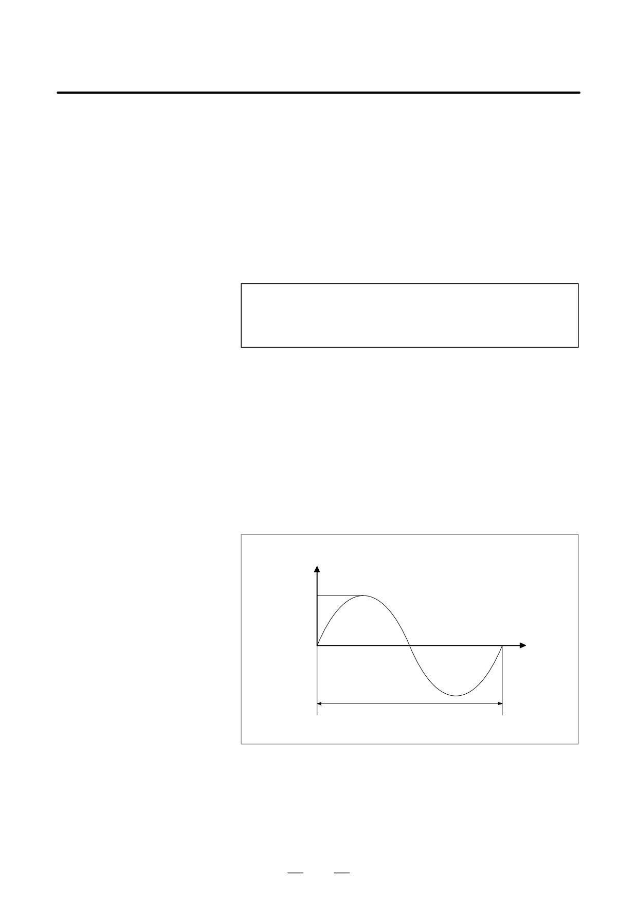
D Sine interpolation
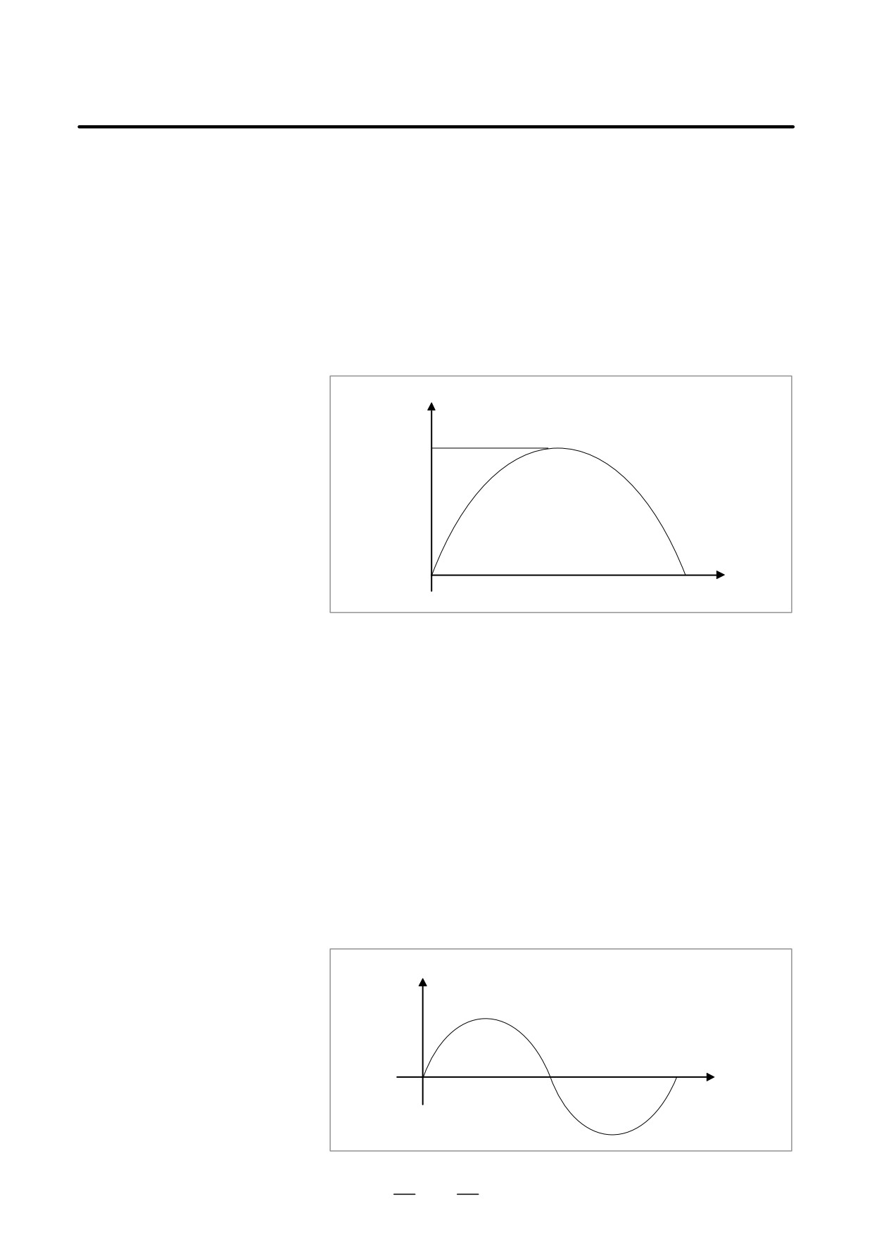
The a axis is regarded as a hypothetical axis for the period of time from
the G07 a 0 command until the G07 a 1 command appears.
Suppose sine interpolation is performed for one cycle in the YZ plane.
The hypothetical axis is them the X axis.
X2 + Y2 = r2 (r is the radius of an arc.)
2p
Y = r SIN (
Z )
1
1 is the distance traveled along the Z-axis in one cycle.)
Y
r
p
2p
Z
0
p
2
1
D Interlock, stroke limit,
Interlock, stroke limit, and external deceleration can also apply to the
and external
hypothetical axis.
deceleration
D Handle interrupt
An interrupt caused by the handle also applies to the hypothetical axis.
This means that movement for a handle interrupt is performed.
66
B-63524EN/01
PROGRAMMING
4. INTERPOLATION FUNCTIONS
Limitations
D Manual operation
The hypothetical axis can be used only in automatic operation. In manual
operation, it is not used, and movement takes place.
D Move command
Specify hypothetical axis interpolation only in the incremental mode.
D Coordinate rotation
Hypothetical axis interpolation does not support coordinate rotation.
Examples
D Sine interpolation
Y
10.0
Z
0
20.0
N001 G07 X0 ;
N002 G91 G17 G03 X-20.0 Y0.0 I-10.0 Z20.0 F100 ;
N003 G01 X10.0 ;
N004 G07 X1 ;
From the N002 to N003 blocks, the X-axis is set to a hypothetical axis.
The N002 block specifies helical cutting in which the Z-axis is the linear
axis. Since no movement takes place along the X axis, movement along
the Y-axis is performed while performing sine interpolation along the
Z-axis.
In the N003 block, there is no movement along the X-axis, and so the
machine dwells until interpolation terminates.
D Changing the feedrate to
(Sample program)
form a sine curve
G07Z0 ;
The Z-axis is set to a hypothetical axis.
G02X0Z0I10.0F4. ; The feedrate on the X-axis changes sinusoidally.
G07Z1 ;
The use of the Z-axis as a hypothetical axis is
canceled.
F
4.0
Xt
67
4. INTERPOLATION FUNCTIONS
PROGRAMMING
B-63524EN/01
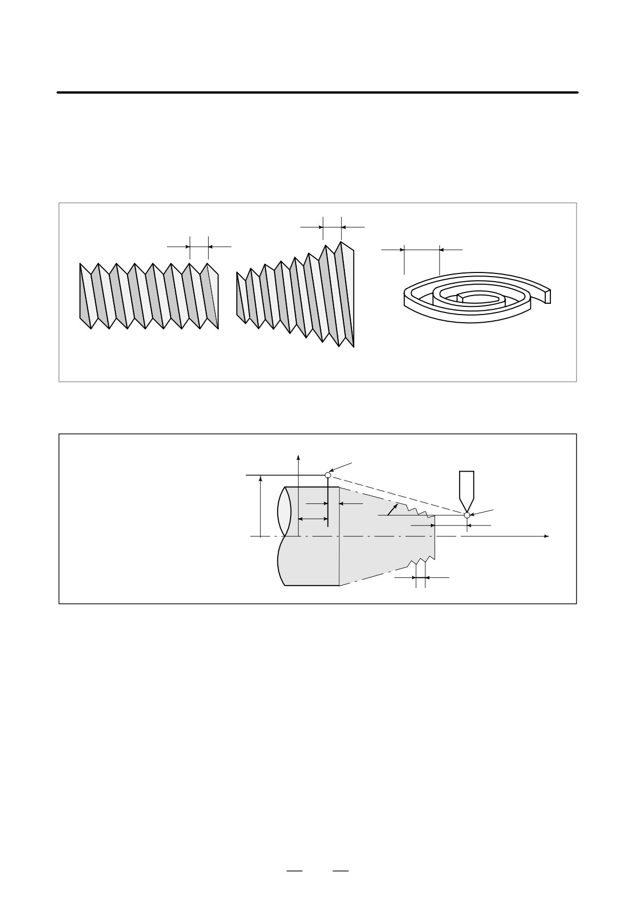
Tapered screws and scroll threads in addition to equal lead straight threads
4.9
can be cut by using a G32 command.
CONSTANT LEAD
The spindle speed is read from the position coder on the spindle in real
THREADING (G32)
time and converted to a cutting feedrate for feed-per minute mode, which
is used to move the tool.
L
L
L
Fig. 4.8 (a) Straight Thread
Fig. 4.8 (b) Tapered Screw
Fig. 4.8 (c) Scroll Thread
Format
X axis
G32IP_F_;
End point
IP_: End point
F_: Lead of the long axis
(always radius programming)
δ2
X
α
Start point
Z
δ1
0
Z axis
L
Fig. 4.9 (d) Example of Thread Cutting
Explanations
In general, thread cutting is repeated along the same tool path in rough
cutting through finish cutting for a screw. Since thread cutting starts when
the position coder mounted on the spindle outputs a 1-turn signal,
threading is started at a fixed point and the tool path on the workpiece is
unchanged for repeated thread cutting. Note that the spindle speed must
remain constant from rough cutting through finish cutting. If not,
incorrect thread lead will occur.
68