FANUC Series 30i/300i/300is-MODEL A. Machining Center System. User's manual - page 235
 

  Index      Manuals     FANUC Series 30i/300i/300is-MODEL A. Machining Center System. User's manual (B-63944EN/03)


Search            copyright infringement  


Content      ..     233      234      235      236     ..


FANUC Series 30i/300i/300is-MODEL A. Machining Center System. User's manual - page 235


12.SETTING AND DISPLAYING DATA

 OPERATION 

B-63944EN/03


- 1836 - 

12.4.27.3 

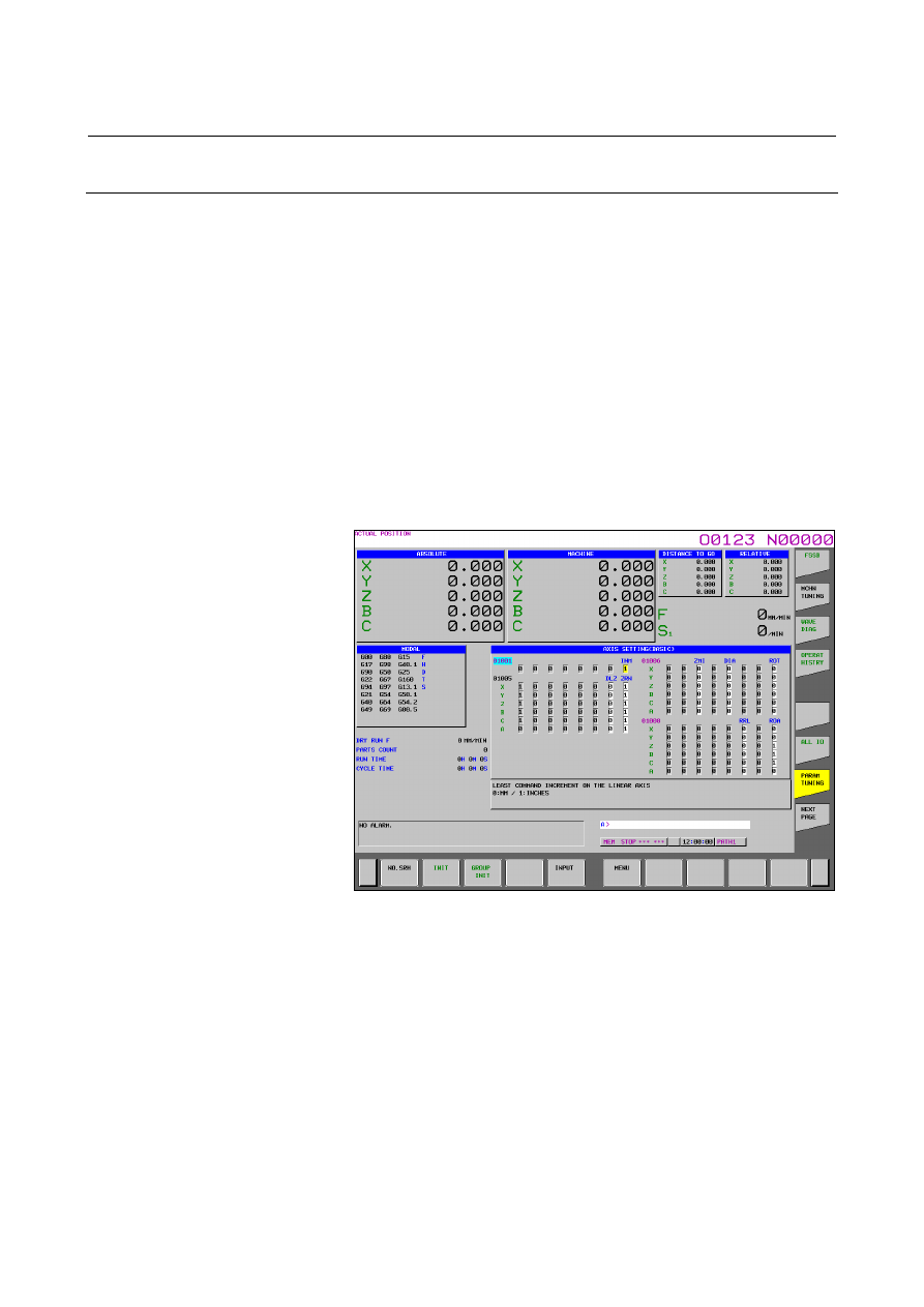
Parameter tuning screen (axis setting) (15-inch display unit) 

 
This screen enables the CNC parameters related to axes, coordinates, 
feedrate, and acceleration/deceleration to be displayed and set. The 
parameters displayed can be divided into four groups: 
(Basic) group : 
 

The parameters related to basic settings are displayed. 

(Coordinate) group : 
 

  The parameters related to coordinates are displayed. 

(Feedrate) group : 
 

The parameters related to feedrate are displayed. 

(Acceleration/deceleration) group: 
 

The parameters related to acceleration/deceleration are displayed. 

The parameters can be initialized to the standard values 
(recommended by FANUC). For the display and setting procedure, see 
the description of the parameter tuning screen (axis setting) in 
Subsection III-12.4.27.2. 


Fig. 12.4.27.3 (a) Parameter tuning screen (axis setting) (15-inch) 


B-63944EN/03

 OPERATION 

12.SETTING AND DISPLAYING DATA


- 1837 - 

12.4.27.4 

Displaying and setting the FSSB amplifier setting screen 

(15-inch display unit) 

 
From the parameter tuning screen, the FSSB amplifier setting screen 
can be displayed. For details of the FSSB amplifier setting screen, see 
the description of the FSSB amplifier setting screen in Subsection 
1.4.4 in the Connection Manual (Function) (B-63943EN-1). 


Fig. 12.4.27.4 (a) FSSB amplifier setting screen (15-inch) 


Fig. 12.4.27.4 (b) FSSB amplifier setting screen 2 (15-inch) 


12.SETTING AND DISPLAYING DATA

 OPERATION 

B-63944EN/03


- 1838 - 

12.4.27.5 

Displaying and setting the FSSB axis setting screen (15-inch 

display unit) 


From the parameter tuning screen, the FSSB axis setting screen can be 
displayed. For details of the FSSB axis setting screen, see the 
description of the FSSB axis setting screen Subsection 1.4.4 in the 
Connection Manual (Function) (B-63943EN-1). 


Fig. 12.4.27.5 (a) FSSB axis setting screen (15-inch) 


B-63944EN/03

 OPERATION 

12.SETTING AND DISPLAYING DATA


- 1839 - 

12.4.27.6 

Displaying and setting the servo setting screen (15-inch 

display unit) 

 
From the parameter tuning screen, the servo setting screen can be 
displayed. For details of the servo setting screen, see the description of 
the servo setting screen in Subsection III-12.4.19. 


Fig. 12.4.27.6 (a) Servo setting screen (15-inch) 

12.SETTING AND DISPLAYING DATA

 OPERATION 

B-63944EN/03


- 1840 - 

12.4.27.7 

Parameter tuning screen (spindle setting) (15-inch display 

unit) 

 
The spindle-related parameters can be displayed and modified. 
For the display and setting procedure, see the description of the 
parameter tuning screen (system setting) in Subsection III-12.4.27.2. 


Fig. 12.4.27.7 (a) Parameter tuning screen (spindle setting) (15-inch) 


B-63944EN/03

 OPERATION 

12.SETTING AND DISPLAYING DATA


- 1841 - 

12.4.27.8 

Parameter tuning screen (miscellaneous settings) (15-inch 

display unit) 

 
The parameters related to the allowable number of M code digits and 
whether to display the servo setting and spindle tuning screens can be 
displayed and modified. Moreover, the parameters can be initialized to 
the standard values (recommended by FANUC). 
For the display and setting procedure, see the description of the 
parameter tuning screen (system setting) in Subsection III-12.4.27.2. 


Fig. 12.4.27.8 (a) Parameter tuning screen (Miscellaneous setting) 

(15-inch) 


12.SETTING AND DISPLAYING DATA

 OPERATION 

B-63944EN/03


- 1842 - 

12.4.27.9 

Displaying and setting the servo tuning screen (15-inch 

display unit) 


From the parameter tuning screen, the servo tuning screen can be 
displayed. For details of the servo tuning screen, see the description of 
the servo tuning screen in Subsection III-12.4.20. 


Fig. 12.4.27.9 (a) Servo tuning screen (15-inch) 


12.4.27.10 

Displaying and setting the spindle tuning screen (15-inch 

display unit) 


From the parameter tuning screen, the spindle tuning screen can be 
displayed. For details of the spindle tuning screen, see the description 
of the spindle tuning screen in Subsection III-12.4.22. 


Fig. 12.4.27.10 (a) Spindle tuning screen (15-inch) 

B-63944EN/03

 OPERATION 

12.SETTING AND DISPLAYING DATA


- 1843 - 

12.4.27.11 

Displaying and setting the machining parameter tuning 

screen (15-inch display unit) 

 
From the parameter tuning screen, the machining parameter tuning 
screen can be displayed.  For details of the machining parameter 
tuning screen, see the description of the machining parameter tuning 
screen in Subsection III-12.4.25. 


Fig. 12.4.27.11 (a) Machining parameter tuning screen (15-inch) 


Explanation 
  - Parameters displayed for parameter tuning 


Table 12.4.27 (a) Parameters displayed for parameter tuning (1) 

Menu Group 

Parameter 

No. 

Name Brief 

description 

Standard 

setting

981 


Sets the path of each axis. 


982 


Sets the path of each spindle. 


983 


Sets the T series/M series of each path.    0:T series/1:M series 


984#0 

LCP  Sets the attribute of each path.  0:Normal/1:Loader control


*1 

3021 


Sets the G/F signal address of each axis. 

*2 

3022 


Sets the G/F signal address of each spindle. 

*3 

3006#0 

GDC  The deceleration signal for reference position return is: 

0:X signal/1:G signal 

3008#2 

XSGx  The signal address allocated to address X is:   

0:Fixed/1:Set by the parameter 

3013 


Address allocated to the deceleration signal for reference position 
return 

*4 

SYSTEM 

SETTING 

System 

setting 

3014 


Bit position allocated to the deceleration signal for reference 
position return 

*5 


Content      ..     233      234      235      236     ..