FANUC Series 30i/300i/300is-MODEL A. Machining Center System. User's manual - page 147
 

  Index      Manuals     FANUC Series 30i/300i/300is-MODEL A. Machining Center System. User's manual (B-63944EN/03)


Search            copyright infringement  


Content      ..     145      146      147      148     ..


FANUC Series 30i/300i/300is-MODEL A. Machining Center System. User's manual - page 147


4.AUTOMATIC OPERATION

 OPERATION 

B-63944EN/03


- 1132 - 

  - Relation with other functions 

The following table indicates the relation between other functions and 
the movement by handle interruption. 

Table 4.6(a)    Relation between other functions and the movement by 

handle interruption 

Signals Relation 

Machine lock 

Machine lock is effective.    When machine lock is on, no 
movement is made due to handle interruption. 

Interlock 

Interlock is effective.    When interlock is on, no movement 
is made due to handle interruption. 

Mirror image 

Mirror image is not effective. Interrupt functions on the plus 
direction by plus direction command, even if this signal 
turns on.   


 - Position display 

The following table shows the relation between various position 
display data and the movement by handle interruption. 

Table4.6(b)    relation between various position display data and the 

movement by handle interruption 

Signals Relation 

Absolute coordinate 
value 

Handle interruption does not change absolute 
coordinates. 

Relative coordinate value

Relative coordinates are changed by the travel 
distance specified by handle interruption. 

Machine coordinate 
value 

Machine coordinates are changed by the travel 
distance specified by handle interruption. 


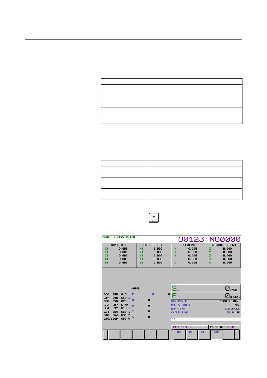
  - Travel distance display 

Press the function key 

, then press the chapter selection soft key 

[HNDL].    The move amount by the handle interruption is displayed. 
The following 4 kinds of data are displayed concurrently. 


Fig. 4.6 (b)     

B-63944EN/03

 OPERATION 

4.AUTOMATIC OPERATION


- 1133 - 

(a) INPUT 

UNIT: 


Handle interruption move amount in input unit system   


Indicates the travel distance specified by handle interruption 
according to the least input increment. 

(b)  OUTPUT UNIT : 
 

Handle interruption move amount in output unit system 


Indicates the travel distance specified by handle interruption 
according to the least command increment. 

(c) RELATIVE: 
 

Position in relative coordinate system 


These values have no effect on the travel distance specified by 
handle interruption. 

(d)  DISTANCE TO GO: 
 

The remaining travel distance in the current block has no effect 
on the travel distance specified by handle interruption. 

The handle interruption move amount is cleared when the manual 
reference position return ends every axis. 
 

  - Display for five-axis systems or better 

Systems having five or more axes provide the same display as the 
overall position display. See III-12.1.3. 
 

Note 

NOTE 

1  In a manual operation mode such as the jog feed 

mode, manual handle feed mode, or TEACH IN 
HANDLE mode, handle interruption cannot be 
performed.  

2  During a machine lock or interlock, handle 

interruption does not cause movement. 

3  Manual handle interruption is disabled for the axis in 

any of the following states. 
-  Follow-up state 
-    PMC axis control state 

4  Manual handle interruption cannot be performed for 

the axis specified in the G00 mode. 


4.AUTOMATIC OPERATION

 OPERATION 

B-63944EN/03


- 1134 - 

4.7 

MIRROR IMAGE 

 
During automatic operation, the mirror image function can be used for 
movement along an axis. To use this function, set the mirror image 
switch to ON on the machine operator's panel, or set the mirror image 
setting to ON from the MDI panel. 

Y

X

Tool

Y-axis mirror image goes on.

Programmed tool
path

Tool path after the
mirror image
function is used


Fig. 4.7 (a)    Mirror image 


Procedure for mirror image 

Procedure 

The following procedure is given as an example. For actual operation, 
refer to the manual supplied by the machine tool builder. 

Press the single block switch to stop automatic operation.   


When the mirror image function is used from the beginning of 
operation, this step is omitted. 

Press the mirror image switch for the target axis on the machine 
operator's panel. 


Alternatively, turn on the mirror image setting by following the 
steps below: 
2-1  Set the MDI mode. 
2-2  Press the function key 

B-63944EN/03

 OPERATION 

4.AUTOMATIC OPERATION


- 1135 - 

2-3  Press the [SETING] soft key for chapter selection to display 

the setting screen. 


Fig. 4.7 (b)    Setting screen 


2-4  Move the cursor to the mirror image setting position, then 

set the target axis to 1. 

3  Enter an automatic operation mode (memory mode or MDI 

mode), then press the cycle start button to start automatic 
operation. 


Explanation 


The mirror image function can also be turned on and off by 
setting bit 0 (MIRx) of parameter No.0012 to 1 or 0. 


For the mirror image switches, refer to the manual supplied by 
the machine tool builder. 


Limitation 

The direction of movement during manual operation, the direction of 
movement from an intermediate point to the reference position during 
automatic reference position return (G28), the direction of approach 
during single direction positioning (G60), and the shift direction in a 
boring cycle (G76, G87) cannot be reversed. 
 

4.AUTOMATIC OPERATION

 OPERATION 

B-63944EN/03


- 1136 - 

4.8 

PROGRAM RESTART 

 
This function specifies Sequence No. of a block to be restarted when a 
tool is broken down or when it is desired to restart machining 
operation after a day off, and restarts the machining operation from 
that block.  It can also be used  as a high-speed program check 
function. 
There are two restart methods:  the P-type method and Q-type 
method. 


B-63944EN/03

 OPERATION 

4.AUTOMATIC OPERATION


- 1137 - 

Procedure for program restart by specifying a sequence number 

Procedure 1   

[P TYPE] 

Retract the tool and replace it with a new one.    When necessary, 
change the offset.    (Go to step 2.) 


[Q TYPE] 

1  When power is turned ON or emergency stop is released, 

perform all necessary operations at that time, including the 
reference position return. 

2  Move the machine manually to the program starting point 

(machining start point), and keep the modal data and coordinate 
system in the same conditions as at the machining start. 

If necessary, modify the offset amount.    (Go to step 2.) 


Procedure 2 

[COMMON TO P TYPE / Q TYPE] 

Turn the program restart switch on the machine operator's panel 
ON. 

2 Press 

  key to display the desired program. 

Find the program head. Press 

 key. 

4  Enter the sequence number of the block to be restarted, then 

press the [P TYPE] or [Q TYPE] soft key. 


If the same sequence number appears more than once, the 
location of the target block must be specified.  Specify a 
frequency and a sequence number. 


xxxxx  


[Q TYPE]
or 
[P TYPE]
Sequence 
number 


xxxyyyyy  


[Q TYPE]
or 
[P TYPE]

Sequence number (The rightmost five digits.) 

Frequency

4.AUTOMATIC OPERATION

 OPERATION 

B-63944EN/03


- 1138 - 

The sequence number is searched for, and the program restart 
screen appears on the LCD display. 


Fig. 4.8 (a)    Program restart screen 


DESTINATION shows the position at which machining is to 
restart. 


DISTANCE TO GO shows the distance from the current tool 
position to the position where machining is to restart.  A 
number to the left of each axis name indicates the order of axes 
(determined by parameter setting) along which the tool moves to 
the restart position. 


The coordinates and amount of travel for restarting the program 
can be displayed for up to four axes.    If your system supports 
five or more axes, pressing the [RSTR] soft key again displays 
the data for the fifth and subsequent axes.   
M :  Up to 35 most recently specified M codes.    The maximum 

number of displayed M codes differs depending on the size 
of the display. 
With 15-inch or 10.4-inch LCD/MDI panel : 
 

Up to 30 M codes 

With 7.2/8.4-inch LCD/MDI panel : Up to 6 M codes 

T  :  Two most recently specified T codes 
S  :  Most recently specified S code 
B  :  Most recently specified B code 


Codes are displayed in the order in which they are specified.  
All codes are cleared by a program restart command or cycle 
start in the reset state. 

Turn the program re-start switch OFF.    At this time, the figure 
at the left side of axis name DISTANCE TO GO blinks. 

Check the screen for the M, S, T, and B codes to be executed.   
If they are found, enter the MDI mode, then execute the M, S, T, 
and B functions.  After execution, restore the previous mode.  
These codes are not displayed on the program restart screen. 

B-63944EN/03

 OPERATION 

4.AUTOMATIC OPERATION


- 1139 - 

Check that the distance indicated under DISTANCE TO GO is 
correct.  Also check whether there is the possibility that the tool 
might hit a workpiece or other objects when it moves to the 
machining restart position.    If such a possibility exists, move the 
tool manually to a position from which the tool can move to the 
machining restart position without encountering any obstacles. 

Press the cycle start button.    The tool moves to the machining 
restart position at the dry run feedrate sequentially along axes in 
the order specified by parameter No. 7310 settings.    Machining 
is then restarted. 


Procedure for program restart by specifying a block Number 

Procedure 1   

[P TYPE] 

Retract the tool and replace it with a new one.    When necessary, 
change the offset.    (Go to step 2.) 


[Q TYPE] 

1  When power is turned ON or emergency stop is released, 

perform all necessary operations at that time, including the 
reference position return. 

2  Move the machine manually to the program starting point 

(machining start point), and keep the modal data and coordinate 
system in the same conditions as at the machining start. 

If necessary, modify the offset amount.    (Go to step 2.) 


Procedure 2 

[COMMON TO P TYPE / Q TYPE] 

Turn the program restart switch on the machine operator's panel 
ON. 

2 Press 

  key to display the desired program. 

Find the program head. Press 

 key. 

Enter the number of the block to be restarted then press the [P 
TYPE] or [Q TYPE] soft key.    The block number cannot exceed 
eight digits. 


B

xxxxxxxx  


[Q TYPE]
or 
[P TYPE]

Block number


Content      ..     145      146      147      148     ..