FANUC Series 30i/300i/300is-MODEL A. Machining Center System. User's manual - page 136
 

  Index      Manuals     FANUC Series 30i/300i/300is-MODEL A. Machining Center System. User's manual (B-63944EN/03)


Search            copyright infringement  


Content      ..     134      135      136      137     ..


FANUC Series 30i/300i/300is-MODEL A. Machining Center System. User's manual - page 136


3.MANUAL OPERATION

 OPERATION 

B-63944EN/03


- 1044 - 


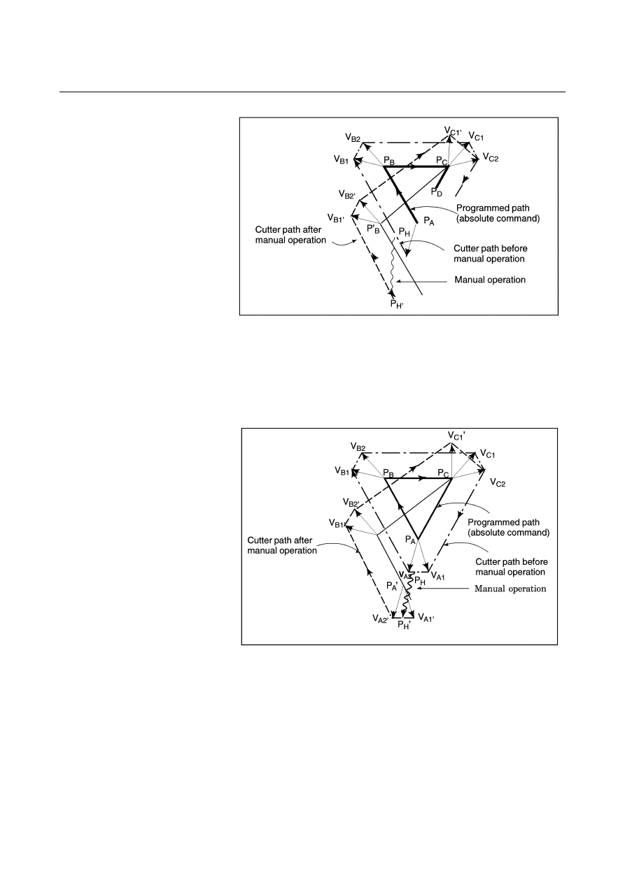
Manual operation during cornering 


This is an example when manual operation is performed during 
cornering. V

A2

', V

B1

', and V

B2

' are vectors moved in parallel with 

V

A2

, V

B1

 and V

B2

 by the amount of manual movement. The new 

vectors are calculated from V

C1

 and V

C2

. Then correct cutter or 

tool nose radius compensation is performed for the blocks 
following P

C


Manual operation after single block stop 


Manual operation was performed when execution of a block was 
terminated by single block stop. 

 Vectors 

V

B1

 and V

B2

 are shifted by the amount of manual 

operation. Sub-sequent processing is the same as case a described 
above. An MDI operation can also be intervened as well as 
manual operation. The movement is the same as that by manual 
operation. 

B-63944EN/03

 OPERATION 

3.MANUAL OPERATION


- 1045 - 


3.MANUAL OPERATION

 OPERATION 

B-63944EN/03


- 1046 - 

3.6 

MANUAL LINEAR/CIRCULAR INTERPOLATION 

 
In manual handle feed or jog feed, the following types of feed 
operations are possible along with the conventional feed operation 
with simultaneous single-axis control (for X, Y, Z, or other axis). 


Feed along a tilted straight line in the XY, YZ, or ZX plane 
based on simultaneous 2-axis control (linear feed) 

  Feed along a circle in the XY, YZ, or ZX plane based on 

simultaneous 2-axis control (circular feed) 


NOTE 

1  Two control axes should be included in the three 

standard axes. 

2  In the following, only the case of the XY plane is 

described.    If any other plane is used, replace XY 
with YZ or ZX.    (Refer to the table below.) 


XY plane 

YZ plane 

ZX plane 

X Y Z 
Y Z X 


Tool 

Workpiece

Tool 

Workpiece 

<Linear feed> 

<Circular feed> 

B-63944EN/03

 OPERATION 

3.MANUAL OPERATION


- 1047 - 

Explanations 
Procedure


For manual handle feed, select the manual handle feed mode.  
For jog feed, select the jog feed mode. 

For manual handle feed, use the handle feed axis selection switch 
to select the feed axis (simultaneous 1-axis feed in the X-, Y-, or 
Z-axis or simultaneous 2-axes feed of the X- and Y-axes along a 
specified line or circle) used when the manual handle is turned. 


For jog feed, use the feed axis direction selection switch to select 
the feed axis and its direction.    The tool moves at the feedrate 
(jog feedrate) set in parameter No. 1423 in the specified axis 
direction or along the specified line or circle while the feed axis 
and its direction are selected. 

3  For the manual handle, the tool moves in the specified axis 

direction when the manual handle is turned.  The feedrate 
depends on the rotation speed of the manual handle.  The 
amount of movement when the manual handle is turned for one 
pulse can be selected by the manual handle feed movement scale 
switch. 


For jog feed, the manual feedrate override dial can be used to 
override the feedrate. 

 
The above procedure is an example.  For actual operation, refer to 
the manual provided by the machine tool builder. 
 

 - Line/circle definition 

A line or circle definition is not required for axis direction feed.    For 
linear or circular feed, however, a line or circle must be defined.  
(For example, in the case of circular feed, the center and radius of the 
circle must be specified.) 
Refer to the manual provided by the machine tool builder. 
 

3.MANUAL OPERATION

 OPERATION 

B-63944EN/03


- 1048 - 

  - Manual handle feed 

In manual handle feed, the tool can be moved along a specified axis 
(X-axis, Y-axis, Z-axis, or N

th

-axis), along a rotated straight line 

(linear feed), or along a circle (circular feed). 
 
(1)  Feed along a specified axis (simultaneous 1-axis control) 
 

A single manual handle operation can move the tool along the 
desired axis, such as X-axis, Y-axis, or Z-axis, on a simultaneous 
1-axis control basis. 


Path of travel using the Y-axis handle

Path of travel using the X-axis handle


Feed along a specified axis 

 
(2)  Linear feed (simultaneous 2-axis control) 
 

A single manual handle operation can move the tool in parallel to 
the straight line on a simltaneous 2-axis control basis.  This 
manual handle is referred to as the "guidance handle".    Also, the 
tool can be moved at right angles to a specified straight line on a 
simultaneous 2-axis control basis.  This manual handle is 
referred to as the "approach handle".    When the guidance handle 
or approach handle is turned clockwise or counterclockwise, the 
tool travels forward or backward along the respective path. 


Path of travel using the 
approach handle 

Path of travel using the 
guidance handle 

Specified straight line

Tool 


Linear feed 


B-63944EN/03

 OPERATION 

3.MANUAL OPERATION


- 1049 - 

(3)  Circular feed (simultaneous 2-axis control) 
 

A single manual handle operation can move the tool from the 
current position along a concentric circle that has the same center 
as a specified circle on a simultaneous 2-axis control basis.  
This manual handle is referred to as the guidance handle.    Also, 
a single manual handle operation can move the tool along a 
straight line normal to a specified circle on simultaneous 2-axis 
control.    This manual handle is refrred to as the approach handle.   
When the guidance handle or approach handle is turned 
clockwise or counterclockwise, the tool travels forward or 
backward along the respective path. 


Specified circle


Path of travel using the 
guidance handle


Path of travel using the 
approach handle 

Tool 


Circular feed 


  - Feedrate for manual handle feed 

The feedrate depends on the speed at which a manual handle is turned.   
The distance to be traveled by the tool (along a tangent in the case of 
linear or circular feed) per manual handle pulse can be selected using 
the manual handle feed travel distance magnification switch. 
The approach handle clamp feedrate can be set using parameter No. 
7160.  The guidance handle clamp feedrate can be set using 
parameter No. 7161. 
 

  - Manual handle selection 

Up to five manual handles to be connected.  For information on 
specifying the usage of the manual handle connected to each interface 
(for feed in the axis direction, use as a guidance handle, or use as an 
approach handle), refer to the manual issued by the machine tool 
builder. 
 

  - Direction of movement using manual handles 

When the tool is moved along a straight line or circle using the 
guidance handle or approach handle, the direction of the tool 
movement (for example, whether to make a clockwise or 
counterclockwise movement along a circle) when the handle is turned 
clockwise or counterclockwise can be specified. 
Refer to the manual provided by the machine tool builder. 
 

3.MANUAL OPERATION

 OPERATION 

B-63944EN/03


- 1050 - 

 - Jog feed 

In jog feed, the tool can be moved along a specified axis (X-axis, 
Y-axis, Z-axis, etc.), along a rotated straight line (linear feed), or 
along a circle (circular feed). 
 
(1)  Feed along a specified axis (simultaneous 1-axis control) 
 

While a feed axis and its direction are specified with the feed 
axis direction selection switch, the tool moves in the specified 
axis direction at the feedrate specified in parameter No. 1423.  
The feedrate can be overriden using the manual feedrate override 
dial. 

 
(2)  Linear feed (simultaneous 2-axis control) 
 

By defining a straight line, the tool can be moved as follows: 


While a feed axis and its direction are selected using the 
feed axis direction selection switch, the tool moves along a 
straight line parallel to the specified straight line on a 
simultaneous 2-axis control basis. 


While a feed axis and its direction are selected using the 
feed axis direction selection switch, the tool moves along a 
straight line perpendicular to the specified staight line on a 
simultaneous 2-axis control basis. 


The feedrate in the tangential direction is specified in parameter 
No. 1410. 


The feedrate can be overridden using the manual feedrate 
override dial. 

 
(3)  Circular feed (simultaneous 2-axis control) 
 

By defining a circle, the tool can be moved as follows: 


While a feed axis and its direction are selected using the 
feed axis direction selection switch, the tool moves from the 
current position along the concentric circle that has the 
same center as the specified circle. 


While a feed axis and its direction are selected using the 
feed axis direction selection switch, the tool moves along a 
straight line normal to the specified circle. 


The feedrate in the tangential direction is specified in parameter 
No. 1410.  The feedrate can be overridden using the manual 
feedrate override dial. 


  - Manual handle feed in JOG mode 

Even in JOG mode, manual handle feed can be enabled using bit 0 
(JHD) of parameter No. 7100.    In this case, however, manual handle 
feed is enabled only when the tool is not moved using jog feed. 
 

B-63944EN/03

 OPERATION 

3.MANUAL OPERATION


- 1051 - 

Limitations 
 - Mirror image 

The mirror image function is not available during the manual 
operation.    (The manual operation can be executed when the mirror 
image switch is off and the mirror image setting is off.) 
 

NOTE 


If the tool is operated with the mirror image 
function activated, the normal operation will not be 
guaranteed. 


 - Rotation direction 

When this function is effective, bit 0 (HNGx) of parameter No. 7102 
is invalid which is used to change the axis movement direction with 
respect to the rotation direction of the manual pulse generator.    (The 
rotation direction of the manual pulse generator is always the same as 
the axis movement direction; that is, the operation is the same as when 
bit 0 of parameter No. 7102 is set to "0".) 
 

  - The amount of the shift for manual handle feed 

When this function is effective, parameters No. 12350 and No. 12351 
used to determine the magnification of manual handle feed for each 
axis are invalid and the values of parameter No. 7113 and No. 7114 
are used.  (Parameters No. 7131 and No. 7132 are used for the 
second manual pulse generator, parameters No. 7133 and No. 7134 for 
the third, parameters No. 7135 and No. 7136 for the fourth, and 
parameters No. 7137 and No. 7138 for fifth.) 
 

 - Incremental feed 

This function is invalid for the incremental feed. 
 

 - Synchronous/composite control 

If the axis is set as the synchronous/composite control axis, this 
function is invalid. 


Content      ..     134      135      136      137     ..