FANUC Series 30i/300i/300is-MODEL A. Machining Center System. User's manual - page 16
 

  Index      Manuals     FANUC Series 30i/300i/300is-MODEL A. Machining Center System. User's manual (B-63944EN/03)


Search            copyright infringement  


Content      ..     14      15      16      17     ..


FANUC Series 30i/300i/300is-MODEL A. Machining Center System. User's manual - page 16


4.INTERPOLATION FUNCTIONS

 PROGRAMMING 

B-63944EN/03


- 84 - 

Example 

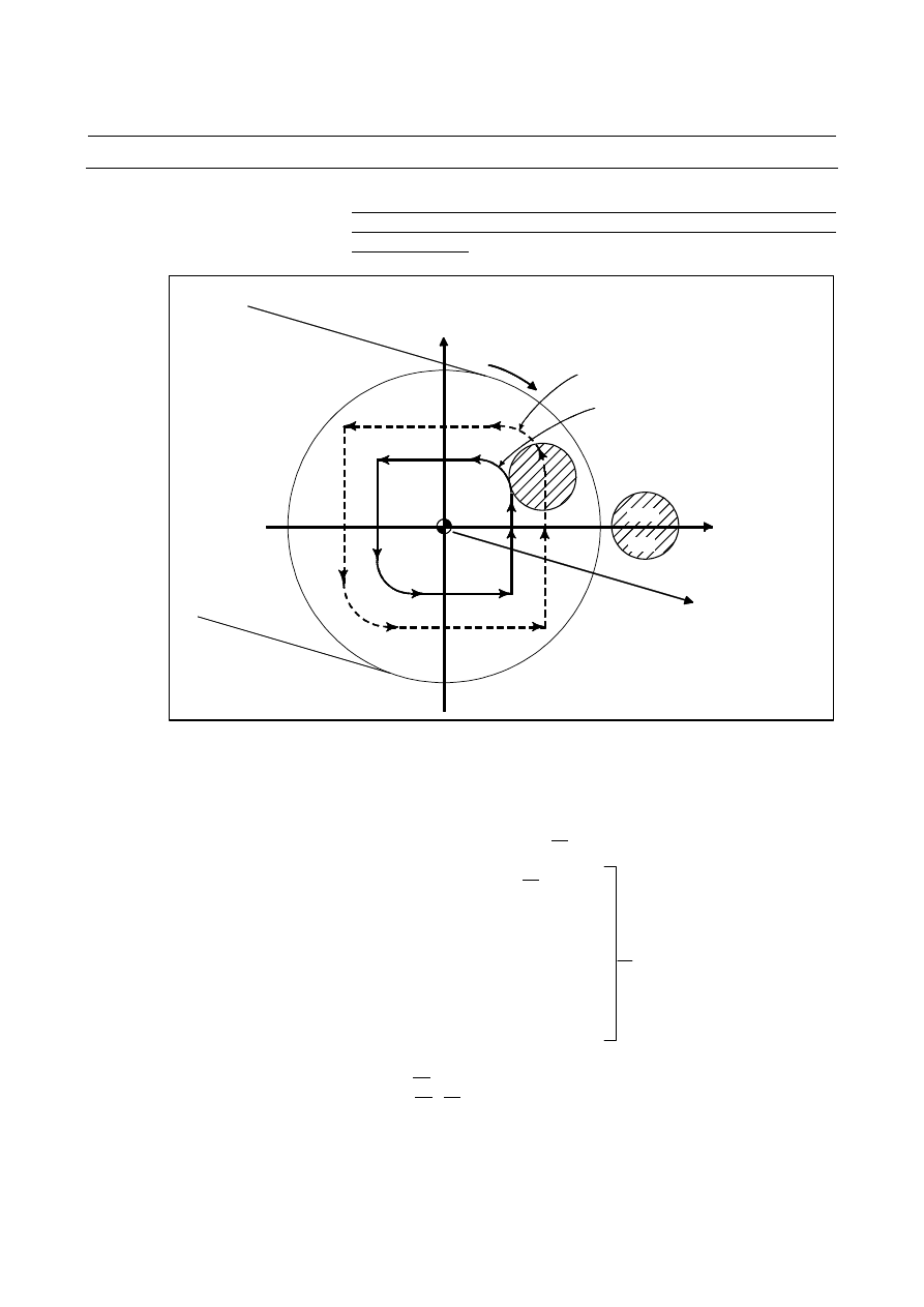
Sample program for polar coordinate interpolation in a Cartesian 
coordinate system consisting of the X-axis (a linear axis) and a 
hypothetical axis 
 

N204

N205

N206

N203

N202

N201

N208

N207

N200

Tool

C axis

Hypothetical axis

Path after cutter compensation

Program path

X axis

Z axis


O001; 
    . 
No10 T0101 
    . 
N0100 G90 G00 X60.0 C0 Z    ; 

Positioning to start point


N0200 G12.1; 


N0201 G42 G01 X20.0F    ; 
N0202 C10.0; 
N0203 G03 X10.0 C20.0 R10.0; 
N0204 G01 X-20.0; 
N0205 C-10.0; 
N0206 G03 X-10.0 C-20.0 I10.0 J0; 
N0207 G01 X20.0; 
N0208 C0; 
N0209 G40 X60.0; 
N0210 G13.1; 
N0300 Z    ; 
N0400 X    C  ; 
    . 
N0900M30; 
 

Start of polar coordinate interpolation

Geometry program 
(program based on cartesian 
coordinates on X 
axis-hypothetical axis plane) 

Cancellation of polar coordinate 
interpolation 

B-63944EN/03

 PROGRAMMING 

4.INTERPOLATION FUNCTIONS


- 85 - 

4.9 

CYLINDRICAL INTERPOLATION (G07.1) 

 
In cylindrical interpolation function, the amount of movement of a 
rotary axis specified by angle is converted to the amount of movement 
on the circumference to allow linear interpolation and circular 
interpolation with another axis. 
Since programming is enabled with the cylinder side face expanded, 
programs such as a program for grooving cylindrical cams can be 
created very easily. 
 

Format 

G07.1 

IP 

r; 

Starts the cylindrical interpolation mode   


(enables cylindrical interpolation).


 : 
 : 
 : 

G07.1 

IP

 0; 

The cylindrical interpolation mode is 
cancelled.


IP 

:


An address for the rotary axis 

r  : The radius of the workpiece 
Specify G07.1 

IP

r; and G07.1 

IP

0; in separate blocks. 

G107 can be used instead of G07.1. 


Explanation 
  - Plane selection (G17, G18, G19) 

To specify a G code for plane selection, set the rotary axis in 
parameter No. 1022 as a linear axis that is one of the basic three axes 
of the basic coordinate system or an axis parallel to one of the basic 
axes. For example, when rotary axis C-axis is assumed to be parallel 
to the X-axis, specifying G17, axis address C, and Y at the same time 
can select a plane formed by the C-axis and Y-axis (the Xp-Yp plane). 
 

T


NOTE 


The U-, V-, and W-axes can be used with G-codes 
B and C. 


 - Feedrate 

A feedrate specified in the cylindrical interpolation mode is the 
feedrate on the circumference. 
 

4.INTERPOLATION FUNCTIONS

 PROGRAMMING 

B-63944EN/03


- 86 - 

  - Circular interpolation (G02, G03) 

Circular interpolation can be performed between the rotary axis set for 
cylindrical interpolation and another linear axis. Radius R is used in 
commands in the same way as described. 
The unit for a radius is not degrees but millimeters (for metric input) 
or inches (for inch input). 
 
<Example Circular interpolation between the Z axis and C axis> 
 

For the C axis of parameter (No.1022), 5 (axis parallel with the X 
axis) is to be set. In this case, the command for circular 
interpolation is 
 G18 

Z_C_; 


G02 (G03) Z_C_R_; 


For the C axis of parameter (No.1022), 6 (axis parallel with the Y 
axis) may be specified instead. In this case, however, the 
command for circular interpolation is   
 G19 

C_Z_; 


G02 (G03) Z_C_R_; 


  - Tool radius/tool nose radius compensation 

To perform tool radius/tool nose radius compensation in the 
cylindrical interpolation mode, cancel any ongoing tool radius/tool 
nose radius compensation mode before entering the cylindrical 
interpolation mode. Then, start and terminate tool radius/tool nose 
radius compensation within the cylindrical interpolation mode. 
 

  - Cylindrical interpolation accuracy 

In the cylindrical interpolation mode, the amount of travel of a rotary 
axis specified by an angle is once internally converted to a distance of 
a linear axis on the outer surface so that linear interpolation or circular 
interpolation can be performed with another axis. After interpolation, 
such a distance is converted back to an angle. For this conversion, the 
amount of travel is rounded to a least input increment. 
So when the radius of a cylinder is small, the actual amount of travel 
can differ from a specified amount of travel. Note, however, that such 
an error is not accumulative. 
If manual operation is performed in the cylindrical interpolation mode 
with manual absolute on, an error can occur for the reason described 
above.


=

 travel

of

amount 


actual


The






×

×

×

×

REV


MOTION

R

2

2

 value

Specified

R

2

2

REV


MOTION

π

π


MOTION REV  : The amount of travel per rotation of the rotary axis 

(360

°

R : 


Workpiece 

radius 

[ ]


:   Rounded to the least input increment 


B-63944EN/03

 PROGRAMMING 

4.INTERPOLATION FUNCTIONS


- 87 - 

Limitation 
  - Arc radius specification in the circular interpolation 

In the cylindrical interpolation mode, an arc radius cannot be specified 
with word address I, J, or K. 
 

 - Positioning 

In the cylindrical interpolation mode, positioning operations 
(including those that produce rapid traverse cycles such as G28, G53, 
G73, G74, G76, G80 to G89) cannot be specified. Before positioning 
can be specified, the cylindrical interpolation mode must be cancelled. 
Cylindrical interpolation (G07.1) cannot be performed in the 
positioning mode (G00). 
 

  - Cylindrical interpolation mode setting 

In the cylindrical interpolation mode, the cylindrical interpolation 
mode cannot be reset. The cylindrical interpolation mode must be 
cancelled before the cylindrical interpolation mode can be reset. 
 

 - Rotary axis 

Only one rotary axis can be set for cylindrical interpolation.  
Therefore, it is impossible to specify more than one rotary axis in the 
G07.1 command. 
 

  - Rotary axis roll-over 

If a rotary axis using the roll-over function is specified at the start of 
the cylindrical interpolation mode, the roll-over function is 
automatically disabled in the cylindrical interpolation mode. After the 
cylindrical interpolation mode is canceled, the roll-over function is 
enabled automatically. 
 

  - Rotary axis control function 

If a rotary axis using the multiple rotary axis control function is 
specified at the start of the cylindrical interpolation mode, the rotary 
axis control function is automatically disabled in the cylindrical 
interpolation mode. After the cylindrical interpolation mode is 
canceled, the rotary axis control function is enabled automatically. 
 

  - Tool radius/tool nose radius compensation 

If the cylindrical interpolation mode is specified when tool radius/tool 
nose radius compensation is already being applied, correct 
compensation is not performed. Specify compensation in the 
cylindrical interpolation mode. 
 

  - Canned cycle for drilling 

Canned cycles (G73, G74, and G81 to G89 for M series / G80 to G89 
for T series) for drilling, cannot be specified during cylindrical 
interpolation mode. 
 

4.INTERPOLATION FUNCTIONS

 PROGRAMMING 

B-63944EN/03


- 88 - 

M


  - Coordinate system setting 

In the cylindrical interpolation mode, a workpiece coordinate system 
(G92, G54 to G59) or local coordinate system (G52) cannot be 
specified. 
 

 - Tool offset 

A tool offset must be specified before the cylindrical interpolation 
mode is set. No offset can be changed in the cylindrical interpolation 
mode. 
 

  - Index table indexing function 

Cylindrical interpolation cannot be specified when the index table 
indexing function is being used. 
 

 - Parallel axis 

The rotary axis specified for cylindrical interpolation must not be a 
parallel axis. 
 

T


  - Coordinate system setting 

In the cylindrical interpolation mode, a workpiece coordinate system 
G50 cannot be specified. 
 

  - Mirror image for double turret 

Mirror image for double turret, G68 and G69, cannot be specified 
during cylindrical interpolation mode. 


B-63944EN/03

 PROGRAMMING 

4.INTERPOLATION FUNCTIONS


- 89 - 

Example 


Z

C

230

190

150

mm 

deg

110 

90 

70 

120 

30 

60 70

270

N05 

N06

N07

N08 

N09 

N10

N11

N12

N13 

360

60 

Example of a Cylindrical Interpolation 
O0001 (CYLINDRICAL INTERPOLATION ); 
N01 G00 G90 Z100.0 C0 ; 
N02 G01 G91 G18 Z0 C0 ; 
N03 G07.1 C57299 ;* 
N04 G90 G01 G42 Z120.0 D01 F250. ; 
N05 C30.0 ; 
N06 G03 Z90.0 C60.0 R30.0 ; 
N07 G01 Z70.0 ; 
N08 G02 Z60.0 C70.0 R10.0 ; 
N09 G01 C150.0 ; 
N10 G02 Z70.0 C190.0 R75.0 ; 
N11 G01 Z110.0 C230.0 ; 
N12 G03 Z120.0 C270.0 R75.0 ; 
N13 G01 C360.0 ; 
N14 G40 Z100.0 ; 
N15 G07.1 C0 ; 
N16 M30 ; 
 

(* A command with a decimal point can also be used.)


4.INTERPOLATION FUNCTIONS

 PROGRAMMING 

B-63944EN/03


- 90 - 

4.10 

CUTTING POINT INTERPOLATION FOR CYLINDRICAL 
INTERPOLATION (G07.1) 

 
The conventional cylindrical interpolation function controls the tool 
center so that the tool axis always moves along a specified path on the 
cylindrical surface, towards the rotary axis (cylindrical axis) of the 
workpiece. The cutting point interpolation for cylindrical interpolation 
function controls the tool so that the tangent of the tool and the cutting 
surface of a contour always passes the rotation center of the workpiece. 
This means that the cutting surface of the contour is always 
perpendicular to the cylinder. With this function, the figure on the 
cutting surface can always be kept constant regardless of the tool 
radius compensation value of the tool used. 
 

Format 

This command is specified in the same way as for the 
conventional cylindrical interpolation function. 

G07.1 

IP

r ; 

Circular interpolation mode on start 
(enabling cylindrical interpolation)


:


G07.1 

IP

0 ; 

Circular interpolation mode cancel


IP

  :  One rotary axis address 

r  :  Cylinder radius of rotary axis 
Specify each of G07.1 

IP

r; and G07.1 

IP

0; singly in a block. 

G107 can also be specified. 


Explanation 
  - Comparison with conventional circular interpolation 

As shown in Fig. 4.10 (a), the tool is controlled in the offset axis 
(Y-axis) direction that is perpendicular to the tool center and 
workpiece rotation center. 
 

Workpiece

Rotation

axis

Rotation

axis

Tool

Center of

tool

Y-axis

Conventional cylindrical interpolation

Cylindrical interpolation with this function

Y-axis


Fig. 4.10 (a)    Comparison with conventional circular interpolation 


B-63944EN/03

 PROGRAMMING 

4.INTERPOLATION FUNCTIONS


- 91 - 

  - Cutting point compensation 

(1)  Cutting point compensation between blocks 
 

As shown in Fig. 4.10 (b), cutting point compensation is 
achieved by moving between blocks N1 and N2. 
(a)  Let C1 and C2 be the heads of the vectors normal to N1 and 

N2 from S1, which is the intersection of the tool center 
paths of blocks N1 and N2 

(b)  After the tool moves to S1 according to the command of N1, 

the tool moves through V on the C-axis as a result of cutting 

point compensation, then through 

r

V

×

×

180

π

 along the 

Y-axis. 


Z-axis

C-axis on the 
cylindrical surface

Y-axis

S1

C1

C2

N1

N2

V


Tool center path


Programmed path 

V  : C-axis component of C1 - C2
C1  : Cutting surface of block N1


C2  : Cutting surface of block N2


Fig.4.10 (b)    Cutting point compensation between blocks 


(2)  Cutting point compensation in a circular command block 
 

As shown in Fig. 4.10 (c), the movement required for cutting 
point compensation is made simultaneously with circular 
interpolation in block N1. 
(a)  Let C0 be the head of the vector normal to N1 from S0, 

which is the tool center position at the start point of circular 
block N1. Let C1 be the head of the similar vector at the end 
point. 

(b)  As the tool moves from S0 to S1, a superimposed 

movement is made by the C-axis component of (C1 - C2) 
(V in the figure) on the C-axis, and a superimposed 

movement is made by 

r

V

×

×

180

π

 along the Y-axis. 

along the Y-axis.   
That is, the following expressions are valid. As movement 
is made through L as shown in Fig. 4.10 (c), the 
superimposed movements are made on the C-axis and 
Y-axis as follows: 

V

C

=


r

V

Y

)

(

180

=

π


Content      ..     14      15      16      17     ..