FANUC Series 30i/300i/300is-MODEL A. Machining Center System. User's manual - page 14
 

  Index      Manuals     FANUC Series 30i/300i/300is-MODEL A. Machining Center System. User's manual (B-63944EN/03)


Search            copyright infringement  


Content      ..     12      13      14      15     ..


FANUC Series 30i/300i/300is-MODEL A. Machining Center System. User's manual - page 14


4.INTERPOLATION FUNCTIONS

 PROGRAMMING 

B-63944EN/03


- 68 - 

4.7 

SPIRAL INTERPOLATION, CONICAL INTERPOLATION 
(G02, G03) 

 
Spiral interpolation is enabled by specifying the circular interpolation 
command together with a desired number of revolutions or a desired 
increment (decrement) for the radius per revolution. 
Conical interpolation is enabled by specifying the spiral interpolation 
command together with an additional axis of movement, as well as a 
desired increment (decrement) for the position along the additional 
axes per spiral revolution. 
 

Format 
 - Spiral interpolation 

XpYp plane 

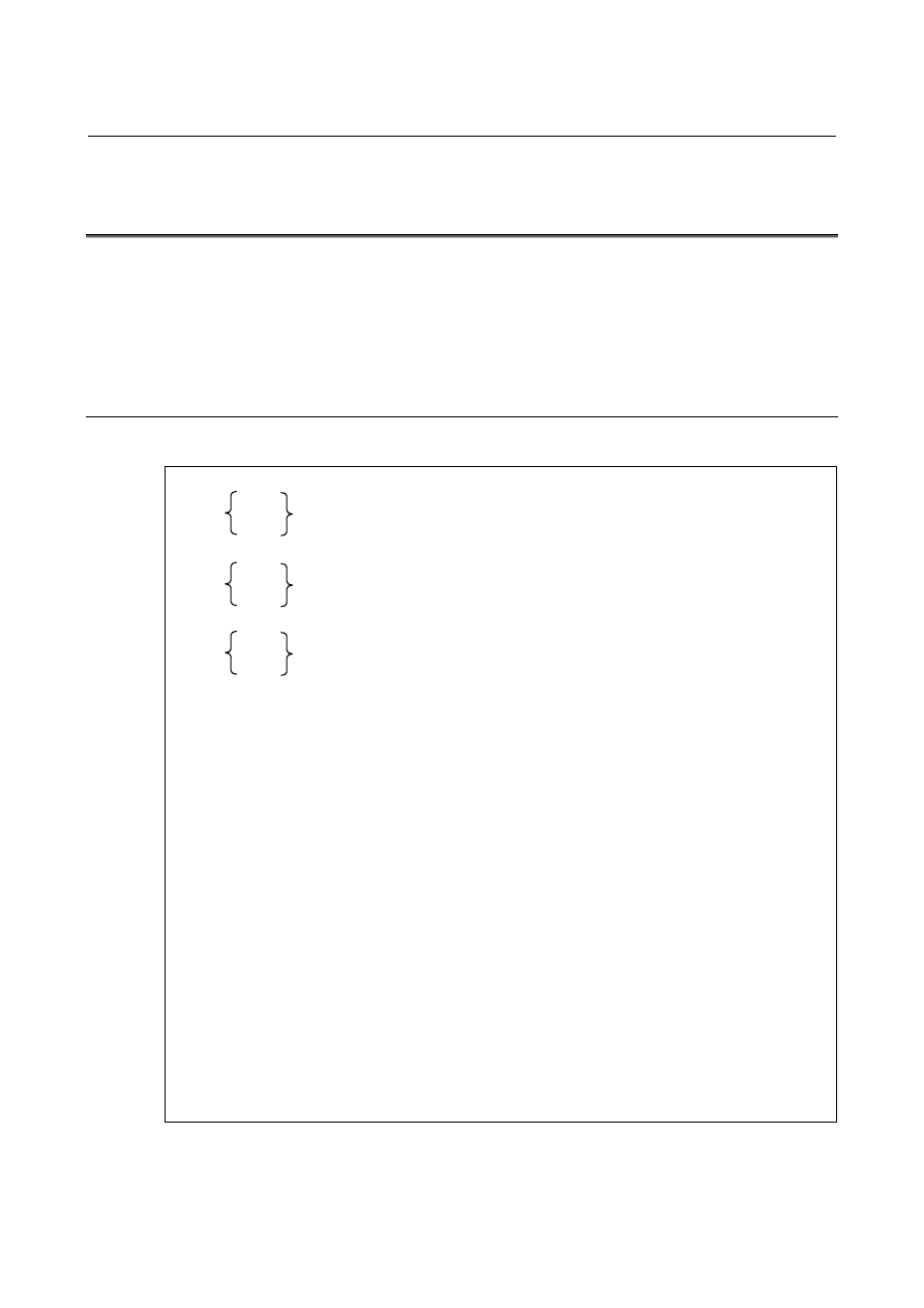
G02 

G17 

G03 

X_Y_I_J_Q_L_F_; 

ZpXp plane 

G02 

G18 

G03 

Z_X_K_I_Q_L_F_; 

YpZp plane 

G02 

G19 

G03 

Y_Z_J_K_Q_L_F_; 

X, Y, Z  : Coordinates of the end point 

: Number of revolutions (positive value without a decimal point) (*1) 

: Radius increment or decrement per spiral revolution (*1, *2) 

I, J, K  : Signed distance from the start point to the center (same as the distance 

specified for circular interpolation) 

F : 

Feedrate 

 
(*1)  Either the number of revolutions (L) or the radius increment or decrement (Q) 

can be omitted. When L is omitted, the number of revolutions is automatically 
calculated from the distance between the current position and the center, the 
position of the end point, and the radius increment or decrement.    When Q is 
omitted, the radius increment or decrement is automatically calculated from the 
distance between the current position and the center, the position of the end 
point, and the number of revolutions. If both L and Q are specified but their 
values contradict, Q takes precedence. Generally, either L or Q should be 
specified. The L value must be a positive value without a decimal point. To 
specify four revolutions plus 90°, for example, round the number of revolutions 
up to five and specify L5. 

(*2)  The increment system for Q depends on the reference axis. 


B-63944EN/03

 PROGRAMMING 

4.INTERPOLATION FUNCTIONS


- 69 - 

 - Conical interpolation 

XpYp plane 

G02 

G17 

G03 

X_ Y_ I_ J_ Z_ Q_ L_ F_ ; 

ZpXp plane 

G02 

G18 

G03 

Z_ X_ K_ I_ Y_ Q_ L_ F_ ; 

YpZp plane 

G02 

G19 

G03 

Y_ Z_ J_ K_ X_ Q_ L_ F_ ; 

X, Y, Z : Coordinates of the end point 

: Number of revolutions (positive value without a decimal point) (*1) 

: Radius increment or decrement per spiral revolution (*1, *2) 

I, J, K  : Two of the three values represent a signed vector from the start point to 

the center. The remaining value is a height increment or decrement per 
spiral revolution in conical interpolation. (*1) 
When the XpYp plane is selected: 
  The I and J values represent a signed vector from the start point to the 

center.    The K value represents a height increment or decrement per 
spiral revolution. 

When the ZpXp plane is selected: 
  The K and I values represent a signed vector from the start point to the 

center.    The J value represents a height increment or decrement per 
spiral revolution. 

When the YpZp plane is selected: 
  The J and K values represent a signed vector from the start point to the 

center.    The I value represents a height increment or decrement per 
spiral revolution. 

: Feedrate (The tangential velocity about the linear axis is specified.) 

(*1)  One of the height increment/decrement (I, J, K), radius increment/decrement 

(Q), and the number of revolutions (L) must be specified. The other two items 
can be omitted. 

 Sample command for the XpYp plane 

G02 K_ 

Q_ 

G18 

G03 

X_ Y_ I_ J_ Z_ 

L_ 

F_ ; 


If both L and Q are specified, but their values contradict, Q takes precedence. 
If both L and a height increment or decrement are specified, but their values 
contradict, the height increment or decrement takes precedence. If both Q 
and a height increment or decrement are specified, but their values 
contradict, Q takes precedence. The L value must be a positive value without 
a decimal point. To specify four revolutions plus 90°, for example, round the 
number of revolutions up to five and specify L5. 

(*2)  The increment system for Q depends on the reference axis. 

4.INTERPOLATION FUNCTIONS

 PROGRAMMING 

B-63944EN/03


- 70 - 

Explanation 
  - Function of spiral interpolation 

Spiral interpolation in the XY plane is defined as follows: 
 

2

2

0

2

0

)

Q'

(R

)

Y

(Y

)

X

(X

+

=

+


X

0

 :  X coordinate of the center 

Y

0

 :  Y coordinate of the center 

R  :  Radius at the beginning of spiral interpolation 
Q' :  Variation in radius 

 
When the programmed command is assigned to this function, the 
following expression is obtained: 


2

2

2

)Q)

360

(L'

(R

J)

Y

(Y

I)

X

(X

S

S

θ

+

+

=

+


 where 

X

S

 :  X coordinate of the start point 

Y

S

 :  Y coordinate of the start point 

I  :  X coordinate of the vector from the start point to the 

center 

J  :  Y coordinate of the vector from the start point to the 

center 

R  :  Radius at the beginning of spiral interpolation 
Q  :  Radius increment or decrement per spiral revolution 
L' :  (Current number of revolutions) - 1 

θ

  :  Angle between the start point and the current position 

(degrees) 


 - Controlled axes 

For conical interpolation, two axes of a plane and two additional axes, 
that is, four axes in total, can be specified. A rotary axis can be 
specified as the additional axis. 
 

B-63944EN/03

 PROGRAMMING 

4.INTERPOLATION FUNCTIONS


- 71 - 

  - Difference between end points 

If the difference between the programmed end point and the calculated 
end point of a spiral exceeds a value specified in parameter No. 3471 
about any axis of a selected plane, an alarm PS5123 will be issued. 
If the difference between the programmed height and calculated height 
of the end point a cone exceeds a value specified in parameter No. 
3471, an alarm PS5123 will be issued. The figure below illustrates 
details. 


G90 G02 X0 Y-33.5 I0 J-100.

F300; 


  Q-20. 
        L4 


The coordinates of the programmed end point are (0, -33.5) while the coordinates of 
the calculated end point are (0, -30.0). A value greater than the difference (

α

:  

Tolerance) is specified in parameter No. 3471. If the end point is exceeded, an alarm 
PS5123 will be issued. The same is specified for the height of conical interpolation. 

-33.5

-30.0

100.0 

Y

X

20.0

20.0

20.0

α


4.INTERPOLATION FUNCTIONS

 PROGRAMMING 

B-63944EN/03


- 72 - 

  - Tool radius compensation 

M


The spiral or conical interpolation command can be programmed in 
tool radius compensation mode. This compensation is performed in 
the same way as described in "When it is exceptional" in "Tool 
Movement in Offset Mode" section. A virtual circle centered on the 
center of spiral interpolation is thought at the end of a block. The tool 
path is obtained by performing tool radius compensation along the 
virtual circle and the blocks before and after the spiral interpolation. 
When the end point of the block is at the center of the spiral 
interpolation, no virtual circle can be drawn. If drawing is attempted, 
an alarm PS5124 is issued. 

Programmed spiral 
interpolation 

Virtual circle 

Tool center path 

r


Center 

After cutter 

compensation 


  - Actual cutting feedrate 

A constant speed is maintained in spiral interpolation or conical 
interpolation. The angular velocity near the center, however, may 
increase because of the small radius of the spiral. This can be avoided 
by maintaining the angular velocity after the radius of the spiral 
reaches a value specified in parameter No. 3472. Consequently, the 
actual cutting feedrate decreases. 
An example is illustrated below. 

Specified feedrate:    F100.
Parameter 3472 (r) = 1.000
IS-B

While the radius of the spiral shown
at the left is greater than the value
specified in parameter No. 3472, the
actual cutting feedrate is F100. As
the radius decreases, the actual
feedrate also decreases, the actual
feedrate near the end point being
about F65.

r

1.5

-0.5


B-63944EN/03

 PROGRAMMING 

4.INTERPOLATION FUNCTIONS


- 73 - 


  - Deceleration by acceleration 

 
During spiral interpolation, the function of deceleration by 
acceleration is enabled. The feedrate may decrease as the tool 
approaches the center of the spiral. 
 

 - Dry run 

When the dry run signal is inverted from 0 to 1 or from 1 to 0 during 
movement along an axis, the movement is accelerated or decelerated 
to the desired speed without first reducing the speed to zero. 
 

Limitation 
 - Radius 

During spiral interpolation and conical interplation, the addresses "C", 
"R", ",C", or ",R" cannot be specified. 
 

 - Feed functions 

The functions of feed per rotation, inverse time feed, F command with 
one digit, and automatic corner override cannot be used. 
 

 - Retrace 

A program including spiral or conical interpolation cannot be retraced. 
 

  - Polar coordinate interpolation, scaling, and normal direction control 

Spiral interpolation and conical interpolation cannot be specified in 
these modes. 
 

 - Optional function 

To use the conical interpolation function, the optional function for 
helical interpolation is also necessary. 
 

4.INTERPOLATION FUNCTIONS

 PROGRAMMING 

B-63944EN/03


- 74 - 

Example 
 - Spiral interpolation 

The path indicated below is programmed with absolute and 
incremental values as follows: 
 

-120 -100  -80 -60  -40 –20     20  40  60  80  100 120

20

Y axis

X axis

40

60

80

100

20. 20.

-20

-40

-60

-80

-100

-120

120


This sample path has the following values: 

  Start point 

:  (0, 100.0) 

  End point (X, Y) 

:    (0, -30.0) 

  Distance to the center (I, J) 

:    (0, -100.0) 

  Radius increment or decrement (Q) :    -20.0 

  Number of revolutions (L) 

:    4 

 
(1)  With absolute values, the path is programmed as follows: 

Q-20.0 

G90 G02 X0 Y-30.0 I0 J-100.0 

L4 

F300.0 ; 

 
(2)  With incremental values, the path is programmed as follows: 

Q-20.0 

G91 G02 X0 Y-130.0 I0 J-100.0

L4 

F300.0 ; 

(Either the Q or L setting can be omitted.) 
 

B-63944EN/03

 PROGRAMMING 

4.INTERPOLATION FUNCTIONS


- 75 - 

 - Conical interpolation 

The sample path shown below is programmed with absolute and 
incremental values as follows: 
 

+Z

+Y

+X

(0,-37.5,62.5)

25.0 25.0

25.0

25.0

100.0

-100.0


This sample path has the following values: 

  Start point 

:    (0, 100.0, 0) 

  End point (X, Y, Z) 

:    (0, -37.5, 62.5) 

  Distance to the center (I, J) 

:    (0, -100.0) 

  Radius increment or decrement (Q) :    -25.0 

  Height increment or decrement (K)  :    25.0 

  Number of revolutions (L) 

:    3 

 
(1)  With absolute values, the path is programmed as follows: 

G90 G02 X0 Y-37.5 Z62.5 I0 J-100.0 

K25.0 

Q-25.0 

L3 

F300.0 ; 

 
(2)  With incremental values, the path is programmed as follows: 

G91 G02 X0 Y-137.5 Z62.5 I0 J-100.0 

K25.0 

Q-25.0 

L3 

F300.0; 

(Either the Q or L setting can be omitted.) 


Content      ..     12      13      14      15     ..