FANUC Series 30i/300i/300is-MODEL A. Machining Center System. User's manual - page 13
 

  Index      Manuals     FANUC Series 30i/300i/300is-MODEL A. Machining Center System. User's manual (B-63944EN/03)


Search            copyright infringement  


Content      ..     11      12      13      14     ..


FANUC Series 30i/300i/300is-MODEL A. Machining Center System. User's manual - page 13


4.INTERPOLATION FUNCTIONS

 PROGRAMMING 

B-63944EN/03


- 60 - 

Explanation 
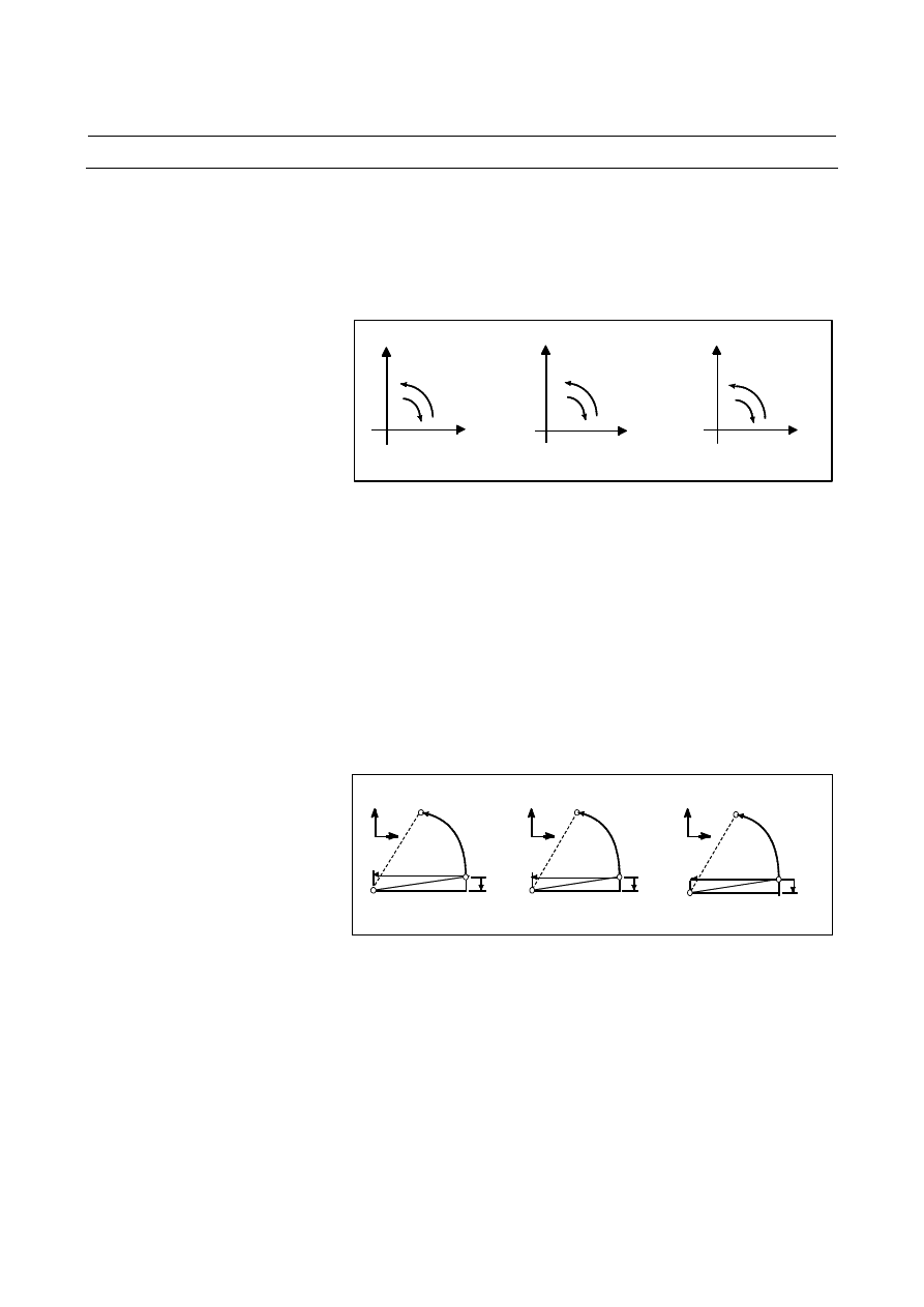
  - Direction of the circular interpolation 

"Clockwise"(G02) and "counterclockwise"(G03) on the XpYp plane 
(ZpXp plane or YpZp plane) are defined when the XpYp plane is 
viewed in the positive-to-negative direction of the Zp axis (Yp axis or 
Xp axis, respectively) in the Cartesian coordinate system. See the 
figure below. 


G02

G03

X

G17

G18

G19 

G02

G03

Z

G02 

G03

Y

Y

Z

X


  - Distance moved on an arc 

The end point of an arc is specified by address Xp, Yp or Zp, and is 
expressed as an absolute or incremental value according to G90 or 
G91. For the incremental value, the distance of the end point which is 
viewed from the start point of the arc is specified with sign. 
 

  - Distance from the start point to the center of arc 

The arc center is specified by addresses I, J, and K for the Xp, Yp, and 
Zp axes, respectively. The numerical value following I, J, or K, 
however, is a vector component in which the arc center is seen from 
the start point, and is always specified as an incremental value 
irrespective of G90 and G91, as shown below. 
I, J, and K must be signed according to the direction. 

End point (x,y)

Center

Start
point

End point (z,x)

End point (y,z)

Start
point

Start
point

Center

Center

i

x

y

x

z

k

z

y

j

j

i

k


I0, J0, and K0 can be omitted. 
If the difference between the radius at the start point and that at the 
end point exceeds the permitted value in a parameter (No.3410), an 
alarm PS0020 occurs. 
 

  - Command for a circle 

When Xp, Yp, and Zp are omitted (the end point is the same as the 
start point) and the center is specified with I, J, and K, a 360

°

 arc 

(circle) is specified. 
G02 I_ ; Command for a circle 
 

B-63944EN/03

 PROGRAMMING 

4.INTERPOLATION FUNCTIONS


- 61 - 

 - Arc radius 

The distance between an arc and the center of a circle that contains the 
arc can be specified using the radius, R, of the circle instead of I, J, 
and K. 
In this case, one arc is less than 180

°

, and the other is more than 180

°


are considered. When an arc exceeding 180

°

 is commanded, the radius 

must be specified with a negative value. If Xp, Yp, and Zp are all 
omitted, if the end point is located at the same position as the start 
point and when R is used, an arc of 0

°

 is programmed   

G02R_ ; (The cutter does not move.) 
 

r=50mm

End point

Start point

r=50mm

<1>

<2>

For arc <1> (less than 180

°

)

      G91 G02 XP60.0 YP55.0 R50.0 F300.0 ;
For arc <2> (greater than 180

°

)

      G91 G02 XP60.0 YP55.0 R-50.0 F300.0 ;

Y

X


 - Feedrate 

The feedrate in circular interpolation is equal to the feedrate specified 
by the F code, and the feedrate along the arc (the tangential feedrate of 
the arc) is controlled to be the specified feedrate. 
The error between the specified feedrate and the actual tool feedrate is 

±

2% or less. However, this feedrate is measured along the arc after the 

tool radius compensation is applied 
 

Limitation 
  - Simultaneously specifying R with I, J, and K 

If I, J, K, and R addresses are specified simultaneously, the arc 
specified by address R takes precedence and the other are ignored. 
 

4.INTERPOLATION FUNCTIONS

 PROGRAMMING 

B-63944EN/03


- 62 - 

  - Specifying an axis that is not contained in the specified plane 

If an axis not comprising the specified plane is commanded, an alarm 
PS0028 occurs. 
For example,   
For milling machining: 
If the X-axis and a U-axis parallel to the X-axis are specified when the 
XY plane is specified 
For lathe cutting: 
If the X-axis and a U-axis parallel to the X-axis are specified when the 
ZX plane is specified with G code system B or C 
 

  - Specifying a semicircle with R 

When an arc having a center angle approaching 180

°

 is specified, the 

calculated center coordinates may contain an error. In such a case, 
specify the center of the arc with I, J, and K. 
 

  - Difference in the radius between the start and end points 

If the difference in the radius between the start and end points of the 
arc exceeds the value specified in parameter No. 3410, alarm PS0020 
is generated. 
When an end point does not lie on the arc, a spiral results, as shown 
below. 


γ

e


γ

(t)


γ

s


Start point

Center 

End point

θ

(t)


θ


Start point

End point


Center 

θ


θ


γ

s


γ

e


Radius

θ

t

s)

e

(

s

(t)

)

(

θ

γ

γ

γ

γ

+

=


The arc radius changes linearly with the center angle 

θ

(t). Spiral 

interpolation is performed using a circular command that specifies one 
arc radius for the start point and another arc radius for the end point. 
To use spiral interpolation, set a large value in parameter No. 3410, 
used to specify the limit on the arc radius error. 

B-63944EN/03

 PROGRAMMING 

4.INTERPOLATION FUNCTIONS


- 63 - 

Example 

M


100

60

40

0

90

120 140


200


60

50

Y axis

X axis


The above tool path can be programmed as follows; 
(1)  In absolute programming 
 

G92X200.0 Y40.0 Z0 ;   


G90 G03 X140.0 Y100.0 R60.0 F300. ;   


G02 X120.0 Y60.0 R50.0 ;   

 or 
 

G92X200.0 Y40.0Z0 ;   


G90 G03 X140.0 Y100.0I-60.0 F300. ; 


G02 X120.0 Y60.0I-50.0 ;   

(2)  In incremental programming 
 

G91 G03 X-60.0 Y60.0 R60.0 F300. ; 


G02 X-20.0 Y-40.0 R50.0 ; 

 or 
 

G91 G03 X-60.0 Y60.0 I-60.0 F300. ; 


G02 X-20.0 Y-40.0 I-50.0 ;   


4.INTERPOLATION FUNCTIONS

 PROGRAMMING 

B-63944EN/03


- 64 - 

T


  - Command of circular interpolation X, Z 

Start point

X

Z-axis

X-axis

Center of arc

End point

Z

K

X

Z-axis

X-axis

(Diameter
programming)

K

Z

Start point

X

Z-axis

X-axis

Center of arc

End point

Z

R

(Diameter

programming)

(Absolute programming)

(Absolute programming)

(Absolute programming)

G02X_Z_I_K_F_;

G03X_Z_I_K_F_;

G02X_Z_R_F_;

(Diameter programming)

I

I

Start point

End point


(Diameter programming) 
   G02X50.0Z30.0I25.0F0.3; or 
   G02U20.0W-20.0I25.0F0.3; or 
   G02X50.0Z30.0R25.0F0.3 or 
   G02U20.0W-20.0R25.F0.3; 

Z

φ

50.0 

10.0 

15.0 

30.0 

50.0 

R25.0 


B-63944EN/03

 PROGRAMMING 

4.INTERPOLATION FUNCTIONS


- 65 - 

4.5 

HELICAL INTERPOLATION (G02, G03) 

 
Helical interpolation which moved helically is enabled by specifying 
up to two other axes which move synchronously with the circular 
interpolation by circular commands. 
 

Format 

Arc in the XpYp plane 

G02 I_ 

J_ 

G17 

G03 

Xp_ Yp_ 

R_ 

α

_ (

β

_) F_ ; 

Arc in the ZpXp plane 

G02 K_ 

I_

G18 

G03 

Zp_ Xp_ 

R_ 

α

_ (

β

_) F_ ; 

Arc in the YpZp plane 

G02 J_ 

K_

G19 

G03 

Yp_ Zp_ 

R_ 

α

_ (

β

_) F_ ; 

α

β

 : Any one axis where circular interpolation is not 

applied. 


Up to two other axes can be specified. 


Explanation 

A tangential velocity of an arc in a specified plane or a tangential 
velocity about the linear axis can be specified as the feedrate, 
depending on the setting of bit 5 (HTG) of parameter No.1403. 
An F command specifies a feedrate along a circular arc, when HTG is 
specified to 0. Therefore, the feedrate of the linear axis is as follows: 

Length of linear axis 

×

Length of circular arc

Determine the feedrate so the linear axis feedrate does not exceed any 
of the various limit values. 


4.INTERPOLATION FUNCTIONS

 PROGRAMMING 

B-63944EN/03


- 66 - 

The feedrate along the circumference of two circular 
interpolated axes is the specified feedrate. 

X

Tool path 


If HTG is set to 1, specify a feedrate along the tool path about the 
linear axis. Therefore, the tangential velocity of the arc is expressed as 
follows: 

Length of arc 

×

(Length of arc)

2

 + (Length of linear axis)

2


The velocity along the linear axis is expressed as follows: 

Length of linear axis 

×

(Length of arc)

2

 + (Length of linear axis)

2


Z

Y

X

The feedrate along the tool path is specified.

Tool path


Limitation 

  Tool radius/tool nose radius compensation is applied only for a 

circular arc. 

  Tool offset and tool length compensation cannot be used in a block 

in which a helical interpolation is commanded. 


B-63944EN/03

 PROGRAMMING 

4.INTERPOLATION FUNCTIONS


- 67 - 

4.6 

HELICAL INTERPOLATION B (G02, G03) 

 
The helical interpolation B function differs from the helical 
interpolation function just in that circular interpolation and a 
movement on four axes outside the specified plane can be 
simultaneously performed. 
For the restrictions and parameters, see the description of the helical 
interpolation function. 
 

Format 

Arc in the XpYp plane 

G02 I_ 

J_ 

G17 

G03 

Xp_ Yp_ 

R_ 

α

β

γ

δ

_ F_ ; 

Arc in the ZpXp plane 

G02 K_ 

I_

G18 

G03 

Zp_ Xp_ 

R_ 

α

β

γ

δ

_ F_ ; 

Arc in the YpZp plane 

G02 J_ 

K_

G19 

G03 

Yp_ Zp_ 

R_ 

α

β

γ

δ

_ F_ ; 

α

β

γ

δ

 : Any axis to which circular interpolation is not 

applied.  


Up to four axes can be specified. 


Content      ..     11      12      13      14     ..