Omron IPC Machine Controller Industrial Panel PC / Industrial Box PC. Software User’s Manual (Industrial PC Platform NY-series) - page 19
Appendices
A-4-5
EtherNet/IP Function Module, Category Name: _EIP
z Functional Classification: EtherNet/IP Communications Errors
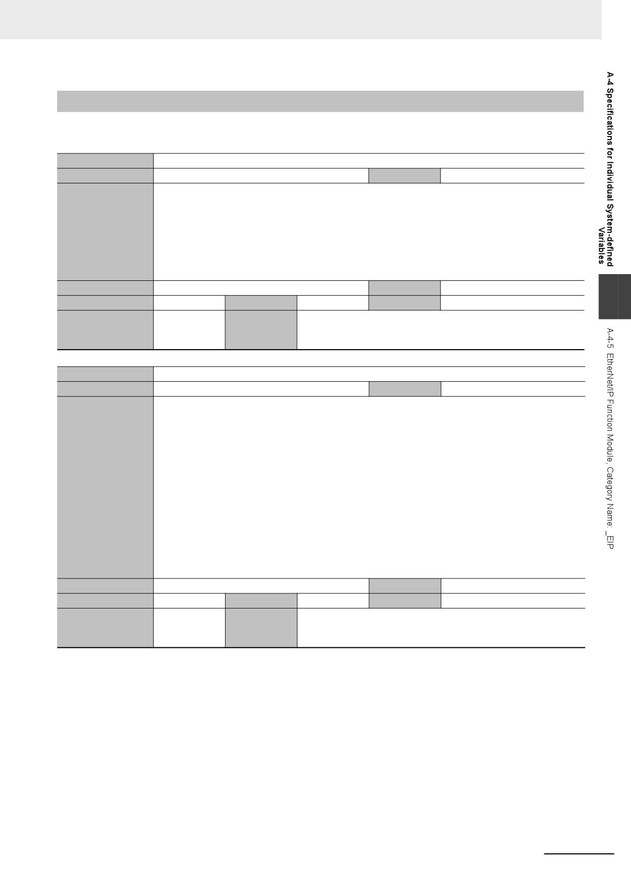
Variable name
_EIP_ErrSta
Meaning
Built-in EtherNet/IP Error
Global/local
Global
Function
This is the error status variable for the built-in EtherNet/IP port.
NY-series Controllers: Represents the collective status of the following error flags.
•
_EIP1_PortErr (Communications Port1 Error)
•
_EIPIn1_PortErr (Internal Port1 Error)
•
_EIP_CipErr (CIP Communications Error)
•
_EIP_TcpAppErr (TCP Application Communications Error)
Note Refer to A-3-6 Meanings of Error Status Bits for the meanings of the error status bits.
Data type
WORD
Range of values
16#0000 to 16#00F0
A
R/W access
R
Retained
Not retained.
Network Publish
Published.
Usage in user program
Possible.
Related instruc-
You can access this variable from the user program with the following
tions
instruction.
• GetEIPError
Variable name
_EIP_PortErr
Meaning
Communications Port Error
Global/local
Global
Function
This is the error status variable for the communications port.
NY-series Controllers: Represents the collective status of the following error flags.
•
_EIP1_MacAdrErr (Port1 MAC Address Error)
•
_EIP1_LanHwErr (Port1 Communications Controller Error)
•
_EIP1_EtnCfgErr (Port1 Basic Ethernet Setting Error)
•
_EIP1_IPAdrCfgErr (Port1 IP Address Setting Error)
•
_EIP1_IPAdrDupErr (Port1 IP Address Duplication Error)
•
_EIP1_BootpErr (Port1 BOOTP Server Error)
•
_EIP_DNSCfgErr (DNS Setting Error)
•
_EIP_DNSSrvErr (DNS Server Connection Error)
•
_EIP_IPRTblErr (IP Route Table Error)
Note If a Link OFF Detected or Built-in EtherNet/IP Processing Error occurs, it is recorded in the event log and
then corresponding bit turns ON. Refer to A-3-6 Meanings of Error Status Bits for the meanings of the error
status bits.
Data type
WORD
Range of values
16#0000 to 16#00F0
R/W access
R
Retained
Not retained.
Network Publish
Published.
Usage in user program
Possible.
Related instruc-
You can access this variable from the user program with the following
tions
instruction.
• GetEIPError
A-79
Appendices
Variable name
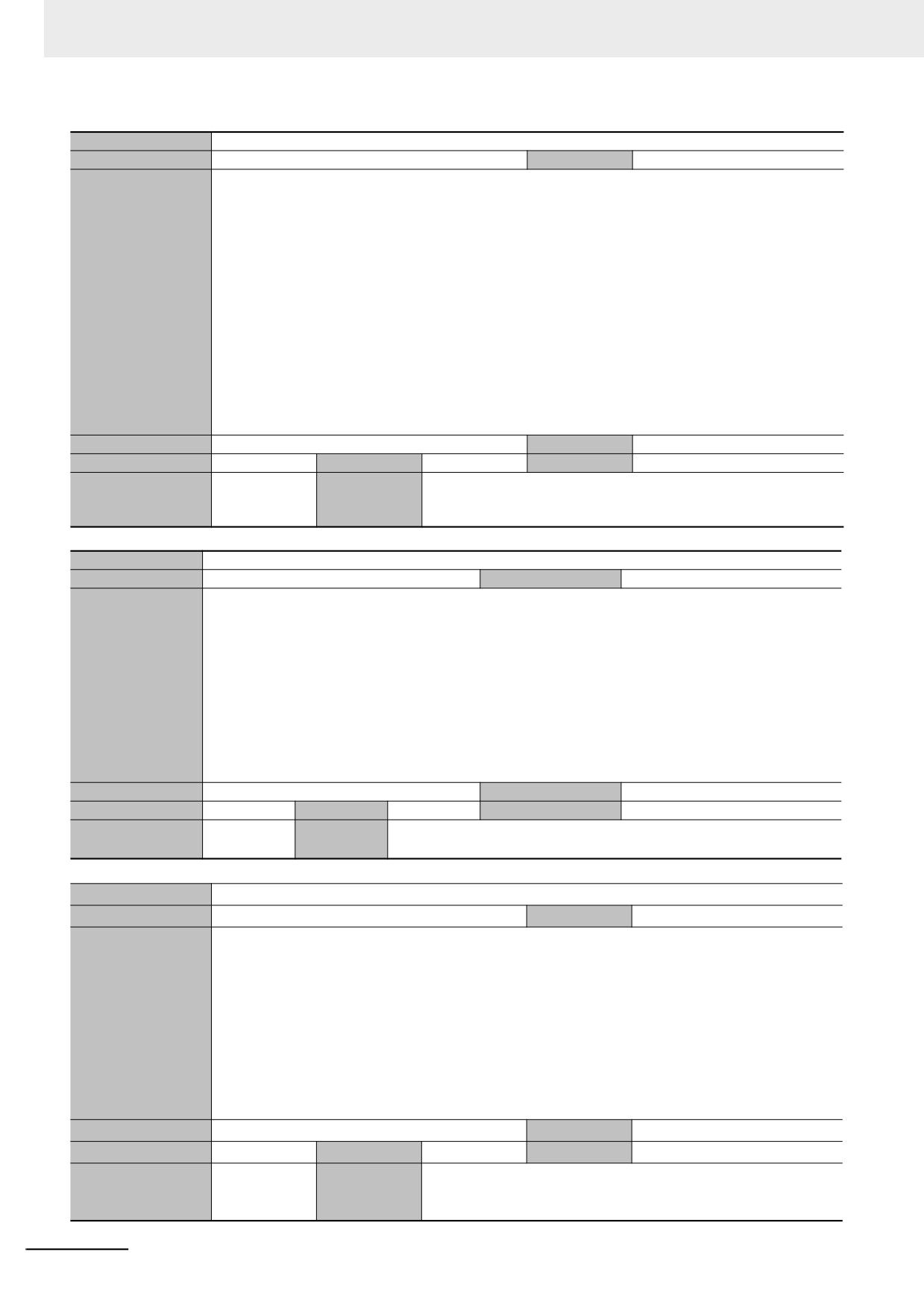
_EIP1_PortErr
Meaning
Communications Port1 Error
Global/local
Global
Function
This is the error status variable for the communications port 1.
It represents the collective status of the following error flags.
•
_EIP1_MacAdrErr (Port1 MAC Address Error)
•
_EIP1_LanHwErr (Port1 Communications Controller Error)
•
_EIP1_EtnCfgErr (Port1 Basic Ethernet Setting Error)
•
_EIP1_IPAdrCfgErr (Port1 IP Address Setting Error)
•
_EIP1_IPAdrDupErr (Port1 IP Address Duplication Error)
•
_EIP1_BootpErr (Port1 BOOTP Server Error)
•
_EIP_DNSCfgErr (DNS Setting Error)
•
_EIP_DNSSrvErr (DNS Server Connection Error)
•
_EIP_IPRTblErr (IP Route Table Error)
Note If a Link OFF Detected or Built-in EtherNet/IP Processing Error occurs, it is recorded in the event log and
then corresponding bit turns ON. Refer to A-3-6 Meanings of Error Status Bits for the meanings of the error
status bits.
Data type
WORD
Range of values
16#0000 to 16#00F0
R/W access
R
Retained
Not retained.
Network Publish
Published.
Usage in user program
Possible.
Related instruc-
You can access this variable from the user program with the following
tions
instruction.
• GetEIPError
Variable name
_EIPIn1_PortErr
Meaning
Internal Port1 Error
Global/local
Global
Function
This is the error status variable for the internal port 1.
It represents the collective status of the following error flags.
•
_EIPIn1_IPAdrCfgErr (Internal Port1 IP Address Setting Error)
•
_EIP1_IPAdrDupErr (Internal Port1 IP Address Duplication Error)
•
_EIP_DNSCfgErr (DNS Setting Error)
•
_EIP_DNSSrvErr (DNS Server Connection Error)
•
_EIP_IPRTblErr (IP Route Table Error)
Note If a Link OFF Detected or Built-in EtherNet/IP Processing Error occurs, it is recorded in the event log and
then corresponding bit turns ON. Refer to A-3-6 Meanings of Error Status Bits on page A-51 for the mean-
ings of the error status bits.
Data type
WORD
Range of values
16#0000 to 16#00F0
R/W access
R
Retained
Not retained.
Network Publish
Published.
Usage in user pro-
Possible.
Related
You can access this variable from the user program with the following instruction.
gram
instructions
• GetEIPError
Variable name
_EIP_CipErr
Meaning
CIP Communications Error
Global/local
Global
Function
This is the error status variable for CIP communications.
NY-series Controller: Represents the collective status of the following error flags.
•
_EIP_IdentityErr (Identity Error)
•
_EIP_TDLinkCfgErr (Tag Data Link Setting Error)
•
_EIP_TDLinkOpnErr (Tag Data Link Connection Failed)
•
_EIP_TDLinkErr (Tag Data Link Communications Error)
•
_EIP_TagAdrErr (Tag Name Resolution Error)
•
_EIP_MultiSwONErr (Multiple Switches ON Error)
Note If a Tag Name Resolution Error occurs, it is recorded in the event log and this variable changes to TRUE.
Refer to A-3-6 Meanings of Error Status Bits for the meanings of the error status bits.
Data type
WORD
Range of values
16#0000 to 16#00F0
R/W access
R
Retained
Not retained.
Network Publish
Published.
Usage in user program
Possible.
Related instruc-
You can access this variable from the user program with the following
tions
instruction.
• GetEIPError
A-80
Appendices
Variable name
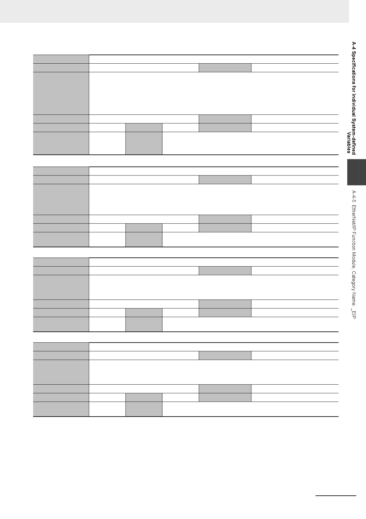
_EIP_TcpAppErr
Meaning
TCP Application Communications Error
Global/local
Global
Function
This is the error status variable for TCP application communications.
It represents the collective status of the following error flags.
•
_EIP_TcpAppCfgErr (TCP Application Setting Error)
•
_EIP_NTPSrvErr (NTP Server Connection Error)
Note Refer to A-3-6 Meanings of Error Status Bits for the meanings of the error status bits.
Data type
WORD
Range of values
16#0000 to 16#00F0
R/W access
R
Retained
Not retained.
Network Publish
Published.
Usage in user program
Possible.
Related
You can access this variable from the user program with the following instruc-
instructions
tion.
• GetEIPError
Variable name
_EIP_MacAdrErr
A
Meaning
MAC Address Error
Global/local
Global
Function
NY-series Controller: Indicates that an error occurred when the MAC address was read on the communications
port 1 at startup.
TRUE: Error
FALSE: Normal
Data type
BOOL
Range of values
TRUE or FALSE
R/W access
R
Retained
Not retained.
Network Publish
Published.
Usage in user program
Possible.
Related
---
instructions
Variable name
_EIP1_MacAdrErr
Meaning
Port1 MAC Address Error
Global/local
Global
Function
Indicates that an error occurred when the MAC address was read on the communications port 1 at startup.
TRUE: Error
FALSE: Normal
Data type
BOOL
Range of values
TRUE or FALSE
R/W access
R
Retained
Not retained.
Network Publish
Published.
Usage in user program
Possible.
Related
---
instructions
Variable name
_EIP_LanHwErr
Meaning
Communications Controller Error
Global/local
Global
Function
NY-series Controller: Indicates that a communications controller failure occurred on the communications port 1.
TRUE: Failure
FALSE: Normal
Data type
BOOL
Range of values
TRUE or FALSE
R/W access
R
Retained
Not retained.
Network Publish
Published.
Usage in user program
Possible.
Related
---
instructions
A-81
Appendices
Variable name
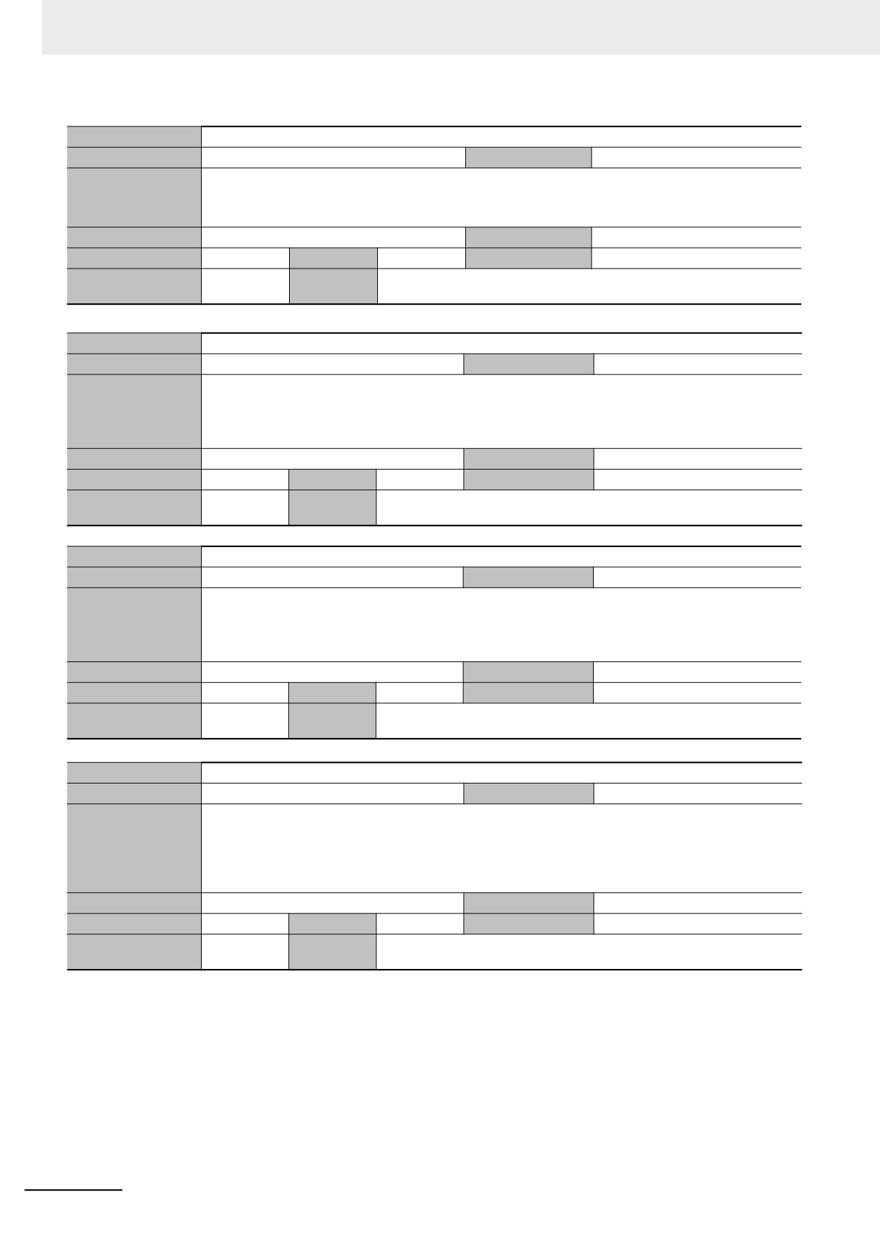
_EIP1_LanHwErr
Meaning
Port1 Communications Controller Error
Global/local
Global
Function
Indicates that a communications controller failure occurred on the communications port 1.
TRUE: Failure
FALSE: Normal
Data type
BOOL
Range of values
TRUE or FALSE
R/W access
R
Retained
Not retained.
Network Publish
Published.
Usage in user program
Possible.
Related
---
instructions
Variable name
_EIP_EtnCfgErr
Meaning
Basic Ethernet Setting Error
Global/local
Global
Function
NY-series Controller: Indicates that the Ethernet communications speed setting (Speed/Duplex) for the communi-
cations port 1 is incorrect. Or, a read operation failed.
TRUE: Setting incorrect or read failed
FALSE: Normal
Data type
BOOL
Range of values
TRUE or FALSE
R/W access
R
Retained
Not retained.
Network Publish
Published.
Usage in user program
Possible.
Related
---
instructions
Variable name
_EIP1_EtnCfgErr
Meaning
Port1 Basic Ethernet Setting Error
Global/local
Global
Function
Indicates that the Ethernet communications speed setting (Speed/Duplex) for the communications port 1 is incor-
rect. Or, a read operation failed.
TRUE: Setting incorrect or read failed
FALSE: Normal
Data type
BOOL
Range of values
TRUE or FALSE
R/W access
R
Retained
Not retained.
Network Publish
Published.
Usage in user program
Possible.
Related
---
instructions
Variable name
_EIP_IPAdrCfgErr
Meaning
IP Address Setting Error
Global/local
Global
Function
NY-series Controller: Indicates the IP address setting errors for the communications port 1.
TRUE:
• There is an illegal IP address setting.
• A read operation failed.
• The IP address obtained from the BOOTP server is inconsistent.
FALSE: Normal
Data type
BOOL
Range of values
TRUE or FALSE
R/W access
R
Retained
Not retained.
Network Publish
Published.
Usage in user program
Possible.
Related
---
instructions
A-82
Appendices
Variable name
_EIP1_IPAdrCfgErr
Meaning
Port1 IP Address Setting Error
Global/local
Global
Function
Indicates the IP address setting errors for the communications port 1.
TRUE:
• There is an illegal IP address setting.
• A read operation failed.
• The IP address obtained from the BOOTP server is inconsistent.
FALSE: Normal
Data type
BOOL
Range of values
TRUE or FALSE
R/W access
R
Retained
Not retained.
Network Publish
Published.
Usage in user program
Possible.
Related
---
instructions
Variable name
_EIPIn1_IPAdrCfgErr
Meaning
Internal Port1 IP Address Setting Error
Global/local
Global
Function
Indicates the IP address setting errors for the internal port 1.
A
TRUE:
• There is an illegal IP address setting.
• A read operation failed.
• The IP address obtained from the BOOTP server is inconsistent.
FALSE: Normal
Data type
BOOL
Range of values
TRUE or FALSE
R/W access
R
Retained
Not retained.
Network Publish
Published.
Usage in user pro-
Possible.
Related
---
gram
instructions
Variable name
_EIP_IPAdrDupErr
Meaning
IP Address Duplication Error
Global/local
Global
Function
NY-series Controller: Indicates that the same IP address is assigned to more than one node for the communica-
tions port 1.
TRUE: Duplication occurred.
FALSE: Other than the above.
Data type
BOOL
Range of values
TRUE or FALSE
R/W access
R
Retained
Not retained.
Network Publish
Published.
Usage in user program
Possible.
Related
---
instructions
Variable name
_EIP1_IPAdrDupErr
Meaning
Port1 IP Address Duplication Error
Global/local
Global
Function
Indicates that the same IP address is assigned to more than one node for the communications port 1.
TRUE: Duplication occurred.
FALSE: Other than the above.
Data type
BOOL
Range of values
TRUE or FALSE
R/W access
R
Retained
Not retained.
Network Publish
Published.
Usage in user program
Possible.
Related
---
instructions
Variable name
_EIPIn1_IPAdrDupErr
Meaning
Internal Port1 IP Address Duplication Error
Global/local
Global
Function
Indicates that the same IP address is assigned to more than one node for the internal port 1.
TRUE: Duplication occurred.
FALSE: Other than the above.
Data type
BOOL
Range of values
TRUE or FALSE
R/W access
R
Retained
Not retained.
Network Publish
Published.
Usage in user pro-
Possible.
Related
---
gram
instructions
A-83
Appendices
Variable name
_EIP_DNSCfgErr
Meaning
DNS Setting Error
Global/local
Global
Function
Indicates that the DNS or hosts settings are incorrect. Or, a read operation failed.
TRUE: Setting incorrect or read failed
FALSE: Normal
Data type
BOOL
Range of values
TRUE or FALSE
R/W access
R
Retained
Not retained.
Network Publish
Published.
Usage in user pro-
Possible.
Related
---
gram
instructions
Variable name
_EIP_BootpErr
Meaning
BOOTP Server Error
Global/local
Global
Function
NY-series Controller: Indicates that a BOOTP server connection failure occurred on the communications port 1.
TRUE: There was a failure to connect to the BOOTP server (timeout).
FALSE: The BOOTP is not enabled, or BOOTP is enabled and an IP address was normally obtained from the
BOOTP server.
Data type
BOOL
Range of values
TRUE or FALSE
R/W access
R
Retained
Not retained.
Network Publish
Published.
Usage in user pro-
Possible.
Related
---
gram
instructions
Variable name
_EIP1_BootpErr
Meaning
Port1 BOOTP Server Error
Global/local
Global
Function
Indicates that a BOOTP server connection failure occurred on the communications port 1.
TRUE: There was a failure to connect to the BOOTP server (timeout).
FALSE: The BOOTP is not enabled, or BOOTP is enabled and an IP address was normally obtained from the
BOOTP server.
Data type
BOOL
Range of values
TRUE or FALSE
R/W access
R
Retained
Not retained.
Network Publish
Published.
Usage in user pro-
Possible.
Related
---
gram
instructions
Variable name
_EIP_IPRTblErr
Meaning
IP Route Table Error
Global/local
Global
Function
NY-series Controller: Indicates that the default gateway settings or IP router table settings are incorrect. Or, a read
operation failed.
TRUE: Setting incorrect or read failed
FALSE: Normal
Data type
BOOL
Range of values
TRUE or FALSE
R/W access
R
Retained
Not retained.
Network Publish
Published.
Usage in user pro-
Possible.
Related
---
gram
instructions
Variable name
_EIP_IdentityErr
Meaning
Identity Error
Global/local
Global
Function
NY-series Controller: Indicates that the identity information for CIP communications 1 (which you cannot overwrite)
is incorrect. Or, a read operation failed.
TRUE: Setting incorrect or read failed
FALSE: Normal
Data type
BOOL
Range of values
TRUE or FALSE
R/W access
R
Retained
Not retained.
Network Publish
Published.
Usage in user pro-
Possible.
Related
---
gram
instructions
A-84
Appendices
Variable name
_EIP_TDLinkCfgErr
Meaning
Tag Data Link Setting Error
Global/local
Global
Function
NY-series Controller: Indicates that the tag data link settings for CIP communications 1 are incorrect. Or, a read
operation failed.
TRUE: Setting incorrect or read failed
FALSE: Normal
Data type
BOOL
Range of values
TRUE or FALSE
R/W access
R
Retained
Not retained.
Network Publish
Published.
Usage in user pro-
Possible.
Related
---
gram
instructions
Variable name
_EIP_TDLinkOpnErr
Meaning
Tag Data Link Connection Failed
Global/local
Global
Function
NY-series Controller: Indicates that establishing a tag data link connection for CIP communications 1 failed.
A
TRUE: Establishing a tag data link connection failed due to one of the following causes.
•The information registered for a target node in the tag data link parameters is different from the actual
node information.
•There was no response from the remote node.
FALSE: Other than the above.
Data type
BOOL
Range of values
TRUE or FALSE
R/W access
R
Retained
Not retained.
Network Publish
Published.
Usage in user pro-
Possible.
Related
---
gram
instructions
Variable name
_EIP_TDLinkErr
Meaning
Tag Data Link Communications Error
Global/local
Global
Function
NY-series Controller: Indicates that a timeout occurred in a tag data link connection for CIP communications 1.
TRUE: A timeout occurred.
FALSE: Other than the above.
Data type
BOOL
Range of values
TRUE or FALSE
R/W access
R
Retained
Not retained.
Network Publish
Published.
Usage in user pro-
Possible.
Related
---
gram
instructions
Variable name
_EIP_TagAdrErr
Meaning
Tag Name Resolution Error
Global/local
Global
Function
NY-series Controller: Indicates that tag resolution for CIP communications 1 failed (i.e., the address could not be identi-
fied from the tag name).
TRUE: Tag resolution failed (i.e., the address could not be identified from the tag name). The following causes are
possible.
•The size of the network variable is different from the tag settings.
•The I/O direction that is set in the tag data link settings does not agree with the I/O direction of the vari-
able in the Controller.
•There is no network variable in the Controller that corresponds to the tag setting.
FALSE: Other than the above.
Data type
BOOL
Range of values
TRUE or FALSE
R/W access
R
Retained
Not retained.
Network Publish
Published.
Usage in user pro-
Possible.
Related
---
gram
instructions
A-85
Appendices
Variable name
_EIP_MultiSwONErr
Meaning
Multiple Switches ON Error
Global/local
Global
Function
NY-series Controller: Indicates that more than one switch turned ON at the same time in CIP communications 1.
TRUE: More than one data link start/stop switch changed to TRUE at the same time.
FALSE: Other than the above.
Data type
BOOL
Range of values
TRUE or FALSE
R/W access
R
Retained
Not retained.
Network Publish
Published.
Usage in user pro-
Possible.
Related
---
gram
instructions
Variable name
_EIP_TcpAppCfgErr
Meaning
TCP Application Setting Error
Global/local
Global
Function
TRUE: At least one of the set values for a TCP application (FTP, NTP, SNMP) is incorrect. Or, a read operation
failed.
FALSE: Normal.
Data type
BOOL
Range of values
TRUE or FALSE
R/W access
R
Retained
Not retained.
Network Publish
Published.
Usage in user pro-
Possible.
Related
---
gram
instructions
Variable name
_EIP_NTPSrvErr
Meaning
NTP Server Connection Error
Global/local
Global
Function
Always FALSE for an NY-series Controller.
Data type
BOOL
Range of values
TRUE or FALSE
R/W access
R
Retained
Not retained.
Network Publish
Published.
Usage in user pro-
Possible.
Related
---
gram
instructions
Variable name
_EIP_DNSSrvErr
Meaning
DNS Server Connection Error
Global/local
Global
Function
TRUE: The DNS client failed to connect to the server (timeout).
FALSE: DNS is not enabled. Or, DNS is enabled and the connection was successful.
Data type
BOOL
Range of values
TRUE or FALSE
R/W access
R
Retained
Not retained.
Network Publish
Published.
Usage in user pro-
Possible.
Related
---
gram
instructions
z Functional Classification: EtherNet/IP Communications Status
Variable name
_EIP_EtnOnlineSta
Meaning
Online
Global/local
Global
Function
NY-series Controller: Indicates that the built-in EtherNet/IP port’s communications can be used via the communications
port 1 (that is, the link is ON, IP address is defined, and there are no errors).
TRUE: The built-in EtherNet/IP port’s communications can be used.
FALSE: The built-in EtherNet/IP port’s communications is disabled due to an error in initial processing, restart pro-
cessing, or link OFF status.
Data type
BOOL
Range of values
TRUE or FALSE
R/W access
R
Retained
Not retained.
Network Publish
Published.
Usage in user pro-
Possible.
Related
---
gram
instructions
A-86
Appendices
Variable name
_EIP1_EtnOnlineSta
Meaning
Port1 Online
Global/local
Global
Function
Indicates that the built-in EtherNet/IP port’s communications can be used via the communications port 1 (that is, the link
is ON, IP address is defined, and there are no errors).
TRUE: The built-in EtherNet/IP port’s communications can be used.
FALSE: The built-in EtherNet/IP port’s communications is disabled due to an error in initial processing, restart pro-
cessing, or link OFF status.
Data type
BOOL
Range of values
TRUE or FALSE
R/W access
R
Retained
Not retained.
Network Publish
Published.
Usage in user pro-
Possible.
Related
---
gram
instructions
Variable name
_EIPIn1_EtnOnlineSta
Meaning
Internal Port1 Online
Global/local
Global
Function
Indicates that the built-in EtherNet/IP port’s communications can be used via the internal port 1 (that is, the link is ON, IP
address is defined, and there are no errors.)
A
TRUE: The built-in EtherNet/IP port’s communications can be used.
FALSE: The communications of the built-in EtherNet/IP port’s internal port 1 is disabled due to an error in initial
processing, restart processing, or link OFF status.
Data type
BOOL
Range of values
TRUE or FALSE
R/W access
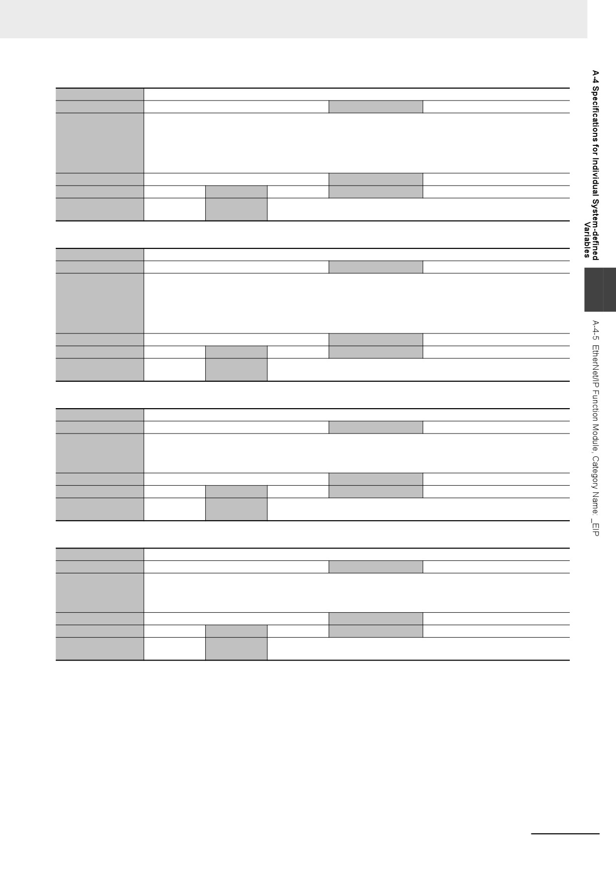
R
Retained
Not retained.
Network Publish
Published.
Usage in user pro-
Possible.
Related
---
gram
instructions
Variable name
_EIP_TDLinkRunSta
Meaning
Tag Data Link Communications Status
Global/local
Global
Function
NY-series Controller: Indicates that at least one connection is in normal operation in CIP communications 1.
TRUE: Normal operation
FALSE: Other than the above.
Data type
BOOL
Range of values
TRUE or FALSE
R/W access
R
Retained
Not retained.
Network Publish
Published.
Usage in user pro-
Possible.
Related
---
gram
instructions
Variable name
_EIP_TDLinkAllRunSta
Meaning
All Tag Data Link Communications Status
Global/local
Global
Function
NY-series Controller: Indicates that all tag data links are communicating in CIP communications 1.
TRUE: Tag data links are communicating in all connections as the originator.
FALSE: An error occurred in at least one connection.
Data type
BOOL
Range of values
TRUE or FALSE
R/W access
R
Retained
Not retained.
Network Publish
Published.
Usage in user pro-
Possible.
Related
---
gram
instructions
A-87
Appendices
Variable name
_EIP_RegTargetSta [255]
Meaning
Registered Target Node Information
Global/local
Global
Function
NY-series Controller: Gives a list of nodes for which built-in EtherNet/IP connections are registered for CIP commu-
nications 1.
This variable is valid only when the built-in EtherNet/IP port is the originator.
Array[x] is TRUE: The connection to the node with a target node ID of x is registered.
Array[x] is FALSE: The connection to the node with a target node ID of x is not registered.
Data type
ARRAY [0..255] OF BOOL
Range of values
TRUE or FALSE
R/W access
R
Retained
Not retained.
Network Publish
Published.
Usage in user pro-
Possible.
Related
---
gram
instructions
Variable name
_EIP_EstbTargetSta [255]
Meaning
Normal Target Node Information
Global/local
Global
Function
NY-series Controller: Gives a list of nodes that have normally established EtherNet/IP connections for CIP commu-
nications 1.
Array[x] is TRUE: The connection to the node with a target node ID of x was established normally.
Array[x] is FALSE: The connection to the node with a target node ID of x was not established, or an error occurred.
Data type
ARRAY [0..255] OF BOOL
Range of values
TRUE or FALSE
R/W access
R
Retained
Not retained.
Network Publish
Published.
Usage in user pro-
Possible.
Related
---
gram
instructions
Variable name
_EIP_TargetPLCModeSta [255]
Meaning
Target PLC Operating Mode
Global/local
Global
Function
NY-series Controller: Shows the operating status of the target node Controllers that are connected for CIP commu-
nications 1, with the built-in EtherNet/IP port as the originator.
The array elements are valid only when the corresponding Normal Target Node Information is TRUE. If the corre-
sponding Normal Target Node Information is FALSE, the Target Node Controller Operating Information indicates
the previous operating status.
Array[x] is TRUE: This is the operating state of the target Controller with a node address of x.
Array[x] is FALSE: Other than the above.
Data type
ARRAY [0..255] OF BOOL
Range of values
TRUE or FALSE
R/W access
R
Retained
Not retained.
Network Publish
Published.
Usage in user pro-
Possible.
Related
---
gram
instructions
Variable name
_EIP_TargetPLCErr [255]
Meaning
Target PLC Error Information
Global/local
Global
Function
NY-series Controller: Shows the error status (logical OR of fatal and non-fatal errors) of the target node Controllers
that are connected for CIP communications 1, with the built-in EtherNet/IP ports as the originator. The array ele-
ments are valid only when the corresponding Normal Target Node Information is TRUE. The immediately preced-
ing value is retained if this variable is FALSE.
Array[x] is TRUE: A fatal or non-fatal error occurred in the target Controller with a target node ID of x.
Array[x] is FALSE: Other than the above.
Data type
ARRAY [0..255] OF BOOL
Range of values
TRUE or FALSE
R/W access
R
Retained
Not retained.
Network Publish
Published.
Usage in user pro-
Possible.
Related
---
gram
instructions
A-88
Appendices
Variable name
_EIP_TargetNodeErr [255]
Meaning
Target Node Error Information
Global/local
Global
Function
NY-series Controller: Indicates that the connection for the Registered Target Node Information for CIP communica-
tions 1 was not established or that an error occurred in the target Controller.
The array elements are valid only when the Registered Target Node Information is TRUE.
Array[x] is TRUE: A connection was not normally established with the target node for a target node ID of x (the Regis-
tered Target Node Information is TRUE and the Normal Target Node Information is FALSE), or a connection was
established with the target node but an error occurred in the target Controller.
Array[x] is FALSE: The target node is not registered for a target node ID of x (the Registered Target Node Informa-
tion is FALSE), or a connection was normally established with the target node (the Registered Target Node Infor-
mation is TRUE and the Normal Target Node Information is TRUE). An error occurred in the target Controller (the
Target PLC Error Information is TRUE).
Data type
ARRAY [0..255] OF BOOL
Range of values
TRUE or FALSE
R/W access
R
Retained
Not retained.
Network Publish
Published.
Usage in user pro-
Possible.
Related
---
gram
instructions
A
Variable name
_EIP_NTPResult
Member name
.ExecTime
Meaning
NTP Last Operation Time
Global/local
Global
Function
NY-series Controller: No change from the initial value.
Data type
Structure: _sNTP_RESULT
Range of values
Depends on data type.
Members: DATE_AND_TIME
R/W access
R
Retained
Not retained.
Network Publish
Published.
Usage in user pro-
Not possible.
Related
You can read the contents of this variable with the GetNTPStatus instruction.
gram
instructions
Variable name
_EIP_NTPResult
Member name
.ExecNormal
Meaning
NTP Operation Result
Global/local
Global
Function
NY-series Controller: No change from the initial value.
Data type
BOOL
Range of values
TRUE or FALSE
R/W access
R
Retained
Not retained.
Network Publish
Published.
Usage in user pro-
Not possible.
Related
You can read the contents of this variable with the GetNTPStatus instruction.
gram
instructions
A-89
Appendices
z Functional Classification: EtherNet/IP Communications Switches
Variable name
_EIP_TDLinkStartCmd
Meaning
Tag Data Link Communications Start Switch
Global/local
Global
Function
NY-series Controller: Change this variable to TRUE to start tag data links for CIP communications 1.
It automatically changes back to FALSE after tag data link operation starts.
Note Do not force this switch to change to FALSE from the user program or from the Sysmac Studio. It changes to
FALSE automatically.
Data type
BOOL
Range of values
TRUE or FALSE
R/W access
R/W
Retained
Not retained.
Network Publish
Published.
Usage in user pro-
Possible.
Related
---
gram
instructions
Variable name
_EIP_TDLinkStopCmd
Meaning
Tag Data Link Communications Stop Switch
Global/local
Global
Function
NY-series Controller: Change this variable to TRUE to stop tag data links for CIP communications 1.
It automatically changes back to FALSE after tag data link operation stops.
Note Do not force this switch to change to FALSE from the user program or from the Sysmac Studio. It changes to
FALSE automatically.
Data type
BOOL
Range of values
TRUE or FALSE
R/W access
R/W
Retained
Not retained.
Network Publish
Published.
Usage in user pro-
Possible.
Related
---
gram
instructions
A-90
Appendices
A-5
Attributes of Controller Data
The following table shows the attributes of the Controller data including the Retain/Non-retain attribute
in the following cases: power interruption, power on, operating mode change, and major fault level Con-
troller error.
Transfer-
ring data
Status changes
with the
Data reten-
Sysmac
Writing
Studio
Operating
tion at
When
Overwrit-
when write
modes
Controller data
power
power is
Change
When a
ing in RUN
protection
permitting
interrup-
turned ON
between
Major Fault
mode
is enabled
writing
tions
PRO-
Level Con-
Synchro-
GRAM
troller
nized data
mode and
Error
RUN mode
occurs
Retained
Same as
Retained.
Retained.
Not sup-
Retained.
PRO-
Supported.
A
POUs and user program
(with non-
before
ported.
GRAM/
User pro-
Online edit-
execution ID in user pro-
volatile
power inter-
RUN mode
gram
ing
gram
memory).
ruption.
(online edit-
ing)
Retained
Same as
Retained.
Retained.
Not sup-
Retained.
PRO-
Not sup-
Task
(with non-
before
ported.
GRAM
ported.
Task Settings
Setup
volatile
power inter-
mode
memory).
ruption.
Retained
Same as
Retained.
Retained.
Not sup-
Retained.
PRO-
Not sup-
Device vari-
(with non-
before
ported.
GRAM
ported.
Variable
able
volatile
power inter-
mode
tables
memory).
ruption.
Variables
(but not
Retained
Same as
Retained.
Retained.
Not sup-
Retained.
PRO-
Supported.
variable
(with non-
before
ported.
GRAM/
User-defined
Online edit-
values)
volatile
power inter-
RUN mode
variables
ing
memory).
ruption.
(online edit-
ing)
Retained
Same as
Retained.
Retained.
Not sup-
Retained.
PRO-
Supported.
(with non-
before
ported.
GRAM/
User-defined
Online edit-
Data type
volatile
power inter-
RUN mode
data types
ing
memory).
ruption.
(online edit-
ing)
Retained
Same as
Retained.
Retained.
Not sup-
Retained.
PRO-
Supported.
CPU Unit
(with non-
before
ported.
GRAM/
name
volatile
power inter-
RUN mode
memory).
ruption.
Controller name
Retained
Same as
Retained.
Retained.
Supported
Not
PRO-
Supported.
Built-in Ether-
(with non-
before
retained.
GRAM/
Net/IP port
volatile
power inter-
RUN mode
name
memory).
ruption.
A-91
Appendices
Transfer-
ring data
Status changes
with the
Data reten-
Sysmac
Writing
Operating
tion at
When
Studio
Overwrit-
when write
modes
Controller data
power
power is
Change
When a
ing in RUN
protection
permitting
interrup-
turned ON
between
Major Fault
mode
is enabled
writing
tions
PRO-
Level Con-
Synchro-
GRAM
troller
nized data
mode and
Error
RUN mode
occurs
Operation Set-
Retained
Same as
Retained.
Retained.
Not sup-
Retained.
CPU Unit
Not sup-
tings
(with non-
before
ported.
name:
ported.
Virtual SD
volatile
power inter-
RUN/PRO-
Memory Card
memory).
ruption.
GRAM
Opera-
settings
mode,
tion Set-
Shutdown wait
Other set-
tings
time settings
tings: PRO-
Event log set-
GRAM
tings
mode
Error settings
Retained
Same as
Retained.
Retained.
Not sup-
Retained.
Write Pro-
Supported.
(with non-
before
ported.
tection and
Protection
Security
volatile
power inter-
other set-
Settings at
Settings
memory).
ruption.
tings: PRO-
Startup
GRAM
mode
Control-
ler Setup
TCP/IP Set-
Retained
Same as
Retained.
Retained.
Not sup-
Retained.
PRO-
Not sup-
tings, Built-in
(with non-
before
ported.
GRAM
ported.
EtherNet/IP
volatile
power inter-
mode
Port Link Set-
memory).
ruption.
tings, Service
Settings.
Built-in
SNMP Set-
Ether-
tings, SNMP
Net/IP
Trap Settings,
Port Set-
NTP Settings,
tings
FTP Settings,
and IP Router
Tables
Tag data link
Retained
Same as
Retained.
Retained.
Supported
Not
PRO-
Not sup-
settings for
(with non-
before
retained.
GRAM/
ported.
built-in Ether-
volatile
power inter-
RUN
Net/IP port
memory).
ruption.
Axis assignments, axis
Retained
Same as
Retained.
Retained.
Not sup-
Retained.
PRO-
Not sup-
Motion
parameter settings, axes
(with non-
before
ported.
GRAM
ported.
Control
group parameter settings,
volatile
power inter-
mode
Setup
MC common parameter
memory).
ruption.
settings
Retained
Same as
Retained.
Retained.
Not sup-
Retained.
PRO-
Not sup-
(with non-
before
ported.
GRAM
ported.
Cam Data
volatile
power inter-
mode
memory).
ruption.
Retained
Same as
Retained.
Retained.
Not sup-
Retained.
RUN/PRO-
Not sup-
Event
Event
User-defined
(with non-
before
ported.
GRAM
ported.
Setting
Setting
error mes-
volatile
power inter-
mode
Table
Table
sages
memory).
ruption.
Ether-
Retained
Same as
Retained.
Retained.
Not sup-
Retained.
PRO-
Not sup-
Ether-
CAT Net-
Network con-
(with non-
before
ported.
GRAM
ported.
CAT Con-
work
figuration
volatile
power inter-
mode
figuratio
Configu-
information.
memory).
ruption.
n
ration
Retained
Same as
Retained.
Retained.
Not sup-
Retained.
PRO-
Not sup-
(with non-
before
ported.
GRAM
ported.
Master
Ether-
Ether-
volatile
power inter-
mode
CAT Set-
CAT Set-
memory).
ruption.
tings
tings
Retained
---
Retained.
Retained.
Supported.
Retained.
RUN/PRO-
Supported.
Settings in
(by slaves).
GRAM
Slaves
mode
Retained
Same as
Retained.
Retained.
Not sup-
Not
PRO-
Not sup-
(with non-
before
ported.
retained.
GRAM
ported.
Operation Authority Verification
volatile
power inter-
mode
memory).
ruption.
A-92
Appendices
Transfer-
ring data
Status changes
with the
Data reten-
Sysmac
Writing
Operating
tion at
When
Studio
Overwrit-
when write
modes
Controller data
power
power is
Change
When a
ing in RUN
protection
permitting
interrup-
turned ON
between
Major Fault
mode
is enabled
writing
tions
PRO-
Level Con-
Synchro-
GRAM
troller
nized data
mode and
Error
RUN mode
occurs
Retained
Same as
Retained.
Retained.
Not sup-
Not
PRO-
Not sup-
User program execution ID in Control-
(with non-
before
ported.
retained.
GRAM
ported.
ler
volatile
power inter-
mode
memory).
ruption.
Values of
User-defined
Not
Initial val-
Initial val-
Initial val-
Supported.
Not
RUN/PRO-
Supported.
non-
variables and
retained.
ues
ues
ues
retained.
GRAM
retained
device vari-
mode
Present
variables
ables
values of
variables
User-defined
Retained
Same as
Retained.
Retained.
Supported.
Not
RUN/PRO-
Supported.
Values of
variables and
(with non-
before
retained.
GRAM
A
retained
device vari-
volatile
power inter-
mode
variables
ables
memory).
ruption.
Retained
Same as
Retained.
Retained.
Supported.
Not
Supported.
Event
System log
(with non-
before
retained.
Logs
logs
User event log
volatile
power inter-
memory).
ruption.
Retained
With Bat-
Retained
Retained
Supported.
Not
RUN/PRO-
Supported.
(with Bat-
tery:
(continued).
(continued).
retained.
GRAM
tery).
Retained
mode
Depends on the specifica-
(contin-
Internal
tions of each system-
ued), With-
clock
defined variable.
out Battery:
Not predict-
able (may
stop).
Retained
Same as
Retained
Retained
Supported.
Not
Not sup-
(with non-
before
(continued).
(continued).
retained.
ported.
Absolute encoder home offset
volatile
power inter-
memory).
ruption.
A-93
Appendices
A-6
Variable Memory Allocation Methods
You must be aware of the way in which memory is allocated to variables to align the memory locations
of the members of structure or union variables with variables in other devices. Adjustments are neces-
sary mainly when structure variables are used in the following type of communications with other
devices.
• When using EtherNet/IP tag data links or CIP messages to access variables between NY-series Con-
troller and other Controllers
• When using structure variables to exchange data with devices other than Controllers, such as ID
Tags
A-6-1
Variable Memory Allocation Rules
The amount of memory and the memory locations that are allocated for a variable depend on the data
type of the variable. The amount of memory and the memory locations that are allocated for array ele-
ments, structure members, and union members depend on the data types, but also on the declarations
that are made for the arrays, structures, and unions.
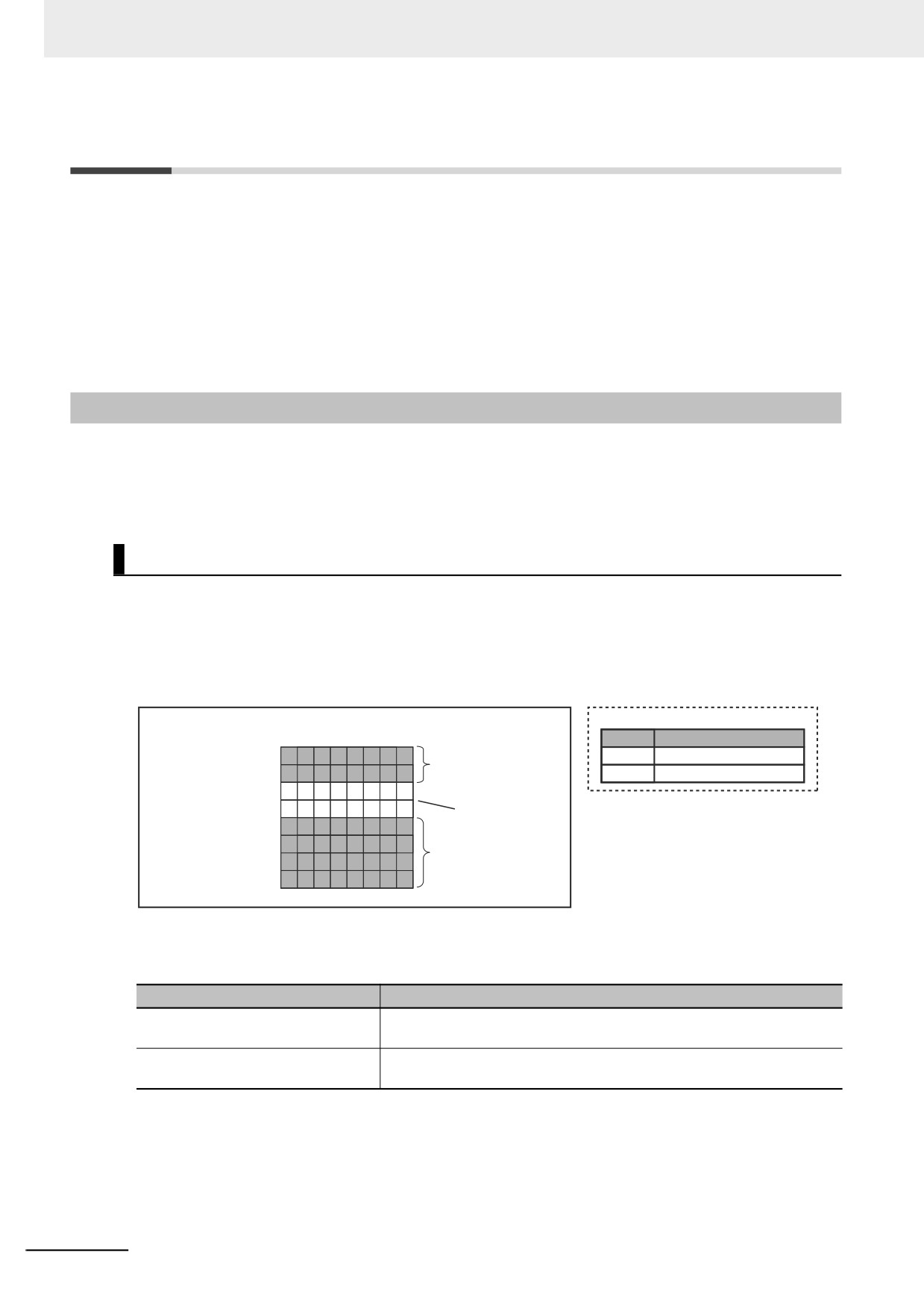
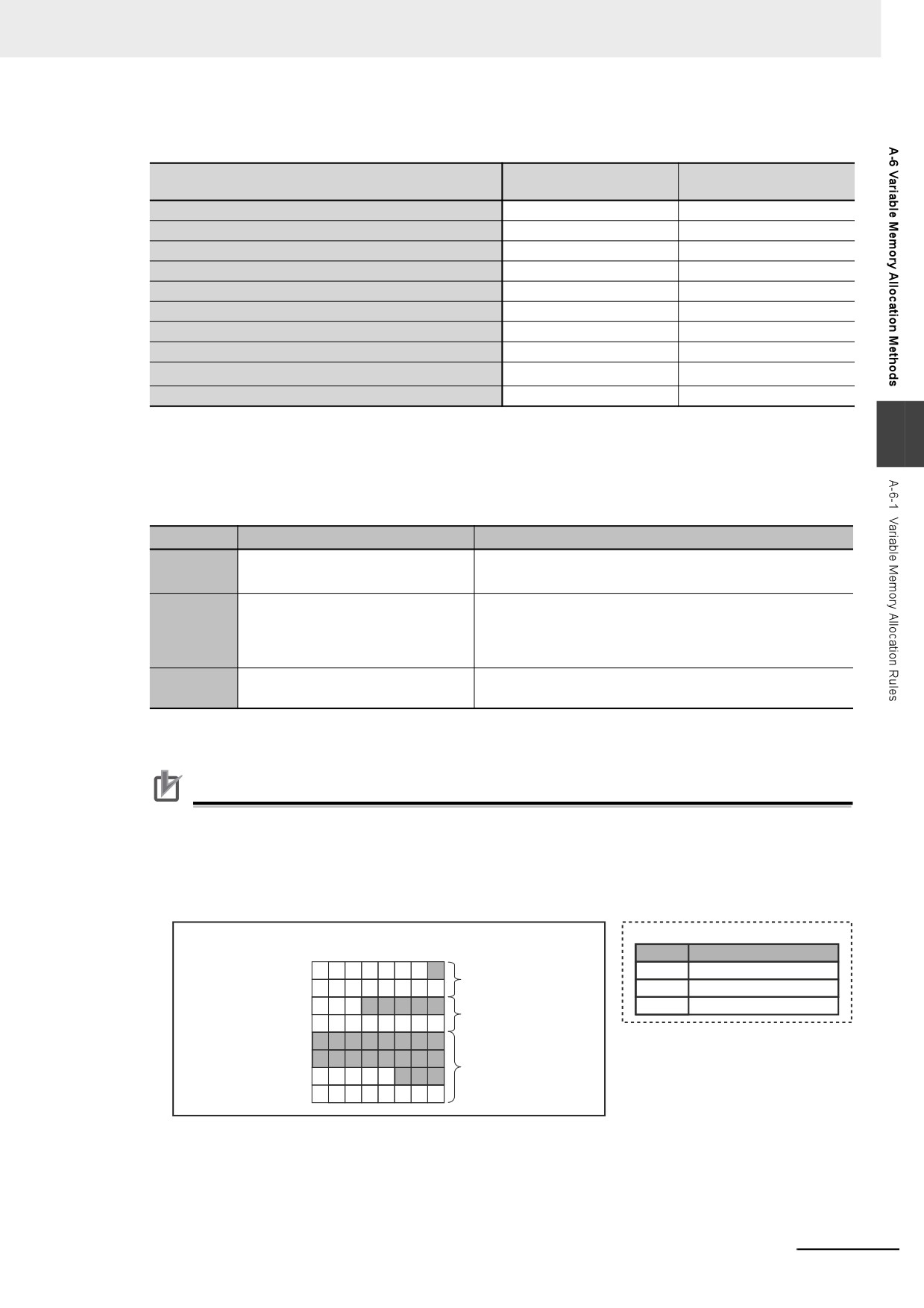
Data Type Alignment and Memory Allocation Amounts
The data size is determined for each data type. The data size is the minimum amount of memory that is
required to store the value or values of that data type. On the other hand, memory for variables is auto-
matically structured by the Controller for the most efficient access. Therefore, the total amount of mem-
ory that is required for variables is not necessarily the total of the data sizes of the variables. For
example, if WORD and DWORD variables are declared, the total of the data sizes is six bytes, but eight
bytes are allocated in memory, as shown in the following figure.
Memory
Variable Table
Bytes
Name
Data type
Variable A
First byte
A
WORD
First byte + 1
WORD data: 2 bytes
B
DWORD
First byte + 2
First byte + 3
Not used: 2 bytes
Variable B First byte + 4
First byte + 5
DWORD data: 4 bytes
First byte + 6
First byte + 7
This information for determining the location of a variable in memory is called the alignment. The align-
ment is determined for each data type. The amount of memory and the memory locations for the vari-
ables are given below.
Item
Specification
Amount of memory that is allocated
An integral multiple of the alignment. However, the minimum amount of
memory is the data size.
Locations in memory
At an integral multiple of the alignment starting from the start of the vari-
able in memory.
A-94
Appendices
The alignments and the amounts of memory that are allocated for the basic data types and enumera-
tions are given below.
Amount of memory that
Data type
Alignment [bytes]
is allocated [bytes]
BOOL
2
2
BYTE, USINT, or SINT
1
1
WORD, UINT, or INT
2
2
DWORD, UDINT, or DINT
4
4
LWORD, ULINT, or LINT
8
8
REAL
4
4
LREAL
8
8
TIME, DATE, TIME_OF_DAY, or DATE_AND_TIME
8
8
1
N+1
STRING[N+1]*1
Enumerations
4
4
*1
N is the maximum number of characters handled. For example, if a maximum of 10 single-byte characters are
handled, the NULL character is added, so memory for 11 characters must be reserved.
A
The elements of arrays and the members of structures and unions are located in memory for the most
efficient access. The alignments and the amounts of memory that are allocated for arrays, structures,
and unions are determined by the variable declarations, as described below.
Data type
Alignment
Amount of memory that is allocated
Same as alignment of the data type
(Amount of memory that is allocated for the data type of the
Array
of the elements
elements) × Number of elements*
The largest alignment of all of the
The integral multiple of the alignment that is larger than the
members
total amount of memory that is allocated when the mem-
Structure
bers are arranged in order at integral multiples of the align-
ment of the data types of the members
The largest alignment of all of the
The largest amount of memory that is allocated for any of
Union
members
the members
* BOOL arrays are an exception. Refer to Precautions for Correct Use, below, for the amount of memory that is
allocated for BOOL arrays.
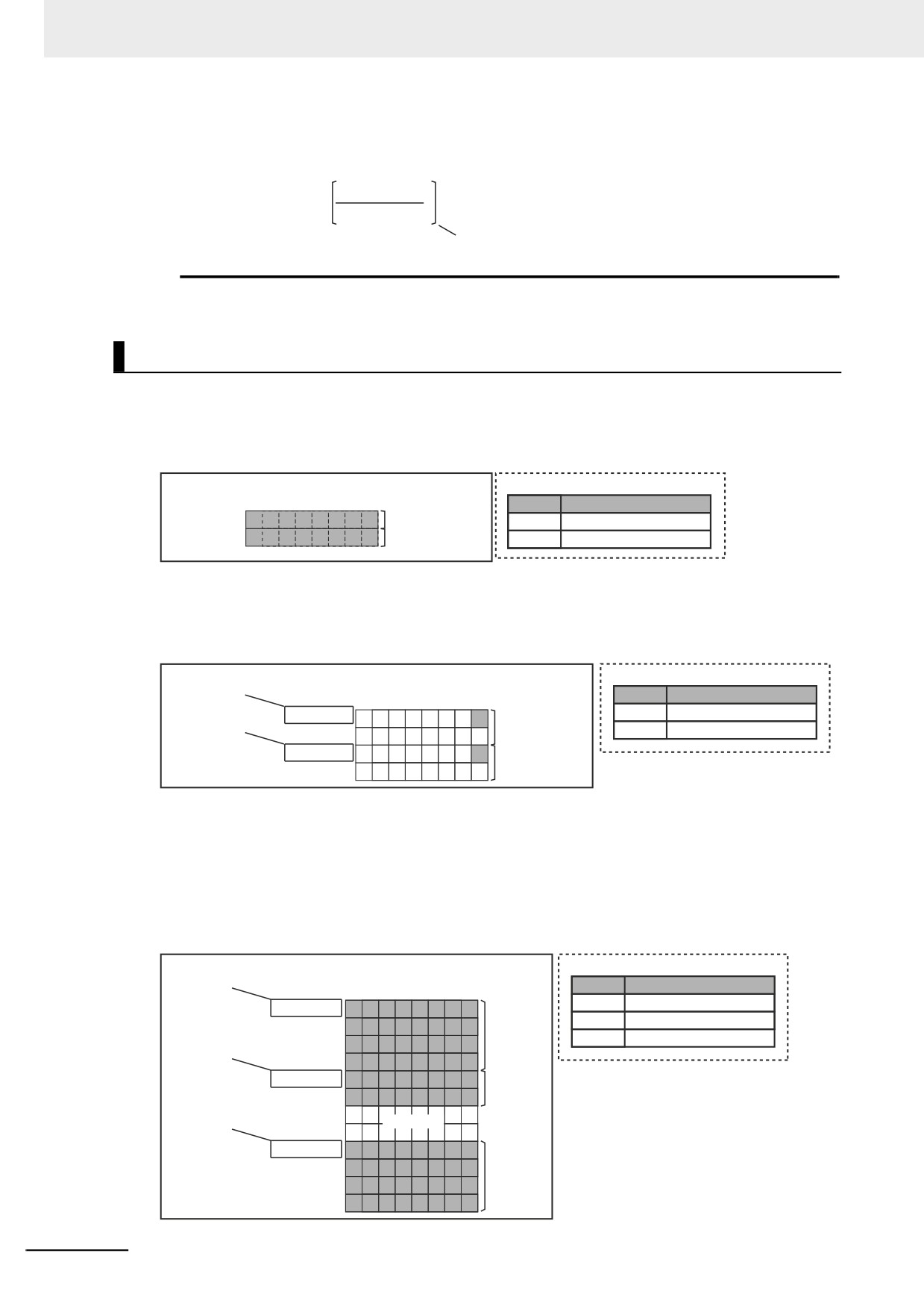
Precautions for Correct Use
Amount of Memory That Is Allocated for BOOL Arrays
Two bytes are allocated in memory for individual BOOL variables, BOOL structure members,
and BOOL union variables. However, for a BOOL array, two bytes of memory are not allocated
for each element. One bit is allocated in order for each element. For the entire array, a multiple of
two bytes of memory is allocated (including unused bits).
Memory
Variable Table
Bytes
Name
Data type
Variable A
First byte
A
BOOL
Two bytes are allocated.
First byte + 1
B
ARRAY[1..5]OF BOOL
Variable B
First byte + 2
C
ARRAY[0..18]OF BOOL
Two bytes are allocated
First byte + 3
for 5 elements.
Variable C First byte + 4
First byte + 5
Four bytes are allocated
First byte + 6
for 19 elements.
First byte + 7
A-95
Appendices
Therefore, the following formula gives the amount of memory that is allocated for a BOOL array.
For 1 to 16 elements, 2 bytes are allocated. For 17 to 32 elements, 4 bytes are allocated.
Number of
elements − 1
Amount of memory = 2
+2
16
Truncate the decimal portion of the result
of the calculation in brackets.
Specific examples of the rules for memory allocation for variables of each data type are given below.
Basic Data Types
z
Variables with One-Byte Alignments (e.g., BYTE)
One byte of memory is allocated for the one-byte alignment.
Example: Two consecutive BYTE variables
Memory
Variable Table
Bytes
Name
Data type
First byte
Variable A, 1 byte
A
BYTE
First byte + 1
Variable B, 1 byte
B
BYTE
z
Variables with Two-byte Alignments (e.g., BOOL and WORD)
Two bytes of memory are allocated for the two-byte alignment.
Example: Two consecutive BOOL variables
First byte +
Variable Table
Memory
(integer multiple of 2)
Name
Data type
Bytes
First byte +
First byte
A
BOOL
(integer multiple of 2)
Variable A, 2 bytes
B
BOOL
First byte + 1
First byte + 2
Variable B, 2 bytes
First byte + 3
z
Variables with Four-byte Alignments (e.g., DWORD)
Four bytes of memory are allocated for the four-byte alignment.
The location of the first byte of data in memory is an integer multiple of four bytes. Therefore, if a
variable with a two-byte alignment, such as WORD data, is inserted, two bytes of unused memory
will remain.
Example: Consecutive variables in the following order: DWORD, WORD, and DWORD
First byte +
Variable Table
Memory
(integer multiple of 4)
Name
Data type
Bytes
A
DWORD
First byte
First byte + 1
Variable A,
B
WORD
First byte +
C
DWORD
First byte + 2
4 bytes
(integer multiple of 2)
First byte + 3
First byte + 4
Variable B,
First byte + 5
2 bytes
First byte +
First byte + 6
(integer multiple of 4)
Not used.
First byte + 7
First byte + 8
First byte + 9
Variable C,
First byte + 10
4 bytes
First byte + 11
A-96
Appendices
z
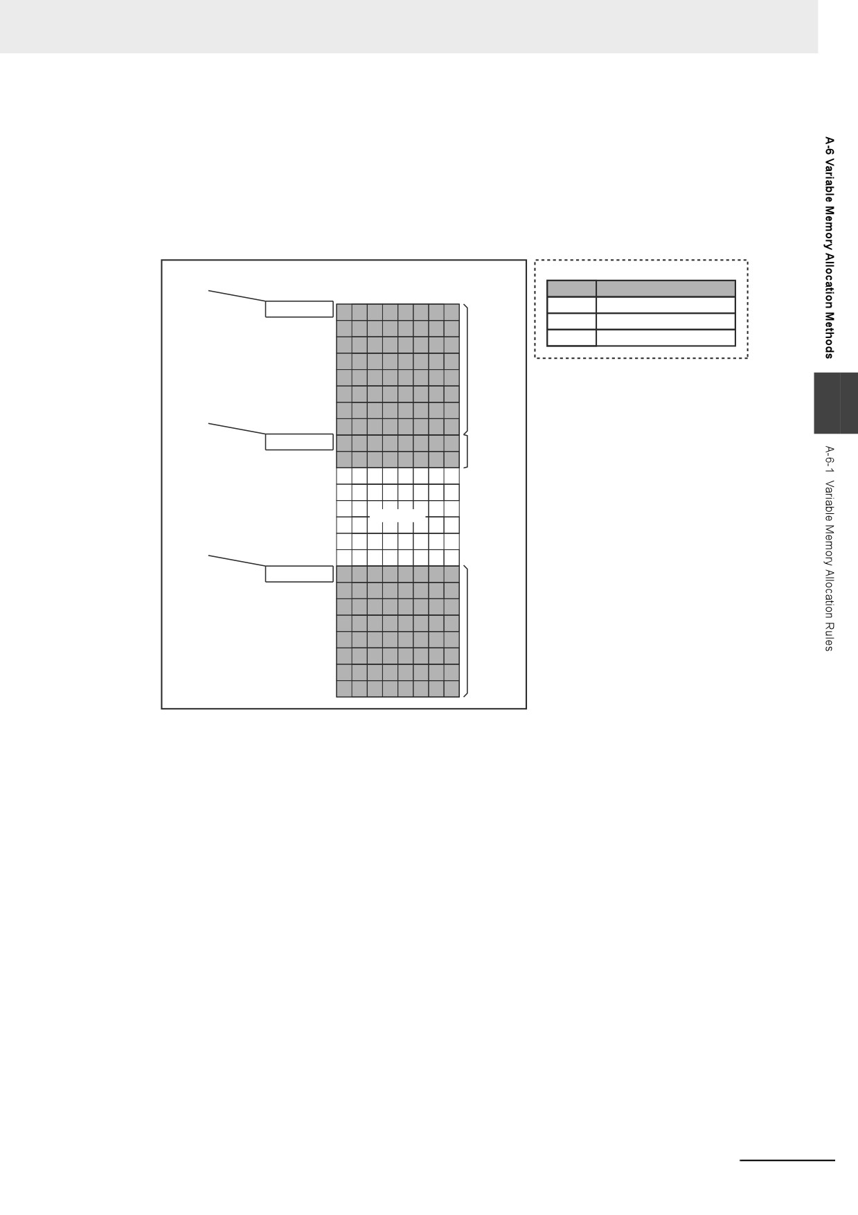
Variables with Eight-byte Alignments (e.g., LWORD)
Eight bytes of memory are allocated for the eight-byte alignment.
The location of the first byte of data in memory is an integer multiple of eight bytes. Therefore, if a
variable with a two-byte alignment, such as WORD data, is inserted, six bytes of unused memory
will remain. If a variable with a four-byte alignment, such as DWORD data, is inserted, four bytes of
unused memory will remain.
Example: Consecutive variables in the following order: LWORD, WORD, and LWORD
First byte +
Variable Table
Memory
(integer multiple of 8)
Name
Data type
Bytes
First byte
A
LWORD
B
WORD
First byte + 1
First byte + 2
C
LWORD
Variable A,
First byte + 3
8 bytes
First byte + 4
First byte + 5
First byte +
A
First byte + 6
(integer multiple of 2)
First byte + 7
First byte + 8
Variable B,
First byte + 9
2 bytes
First byte + 10
First byte + 11
First byte + 12
Not used.
First byte + 13
First byte +
First byte + 14
(integer multiple of 8)
First byte + 15
First byte + 16
First byte + 17
First byte + 18
Variable C,
First byte + 19
8 bytes
First byte + 20
First byte + 21
First byte + 22
First byte + 23
A-97
Appendices
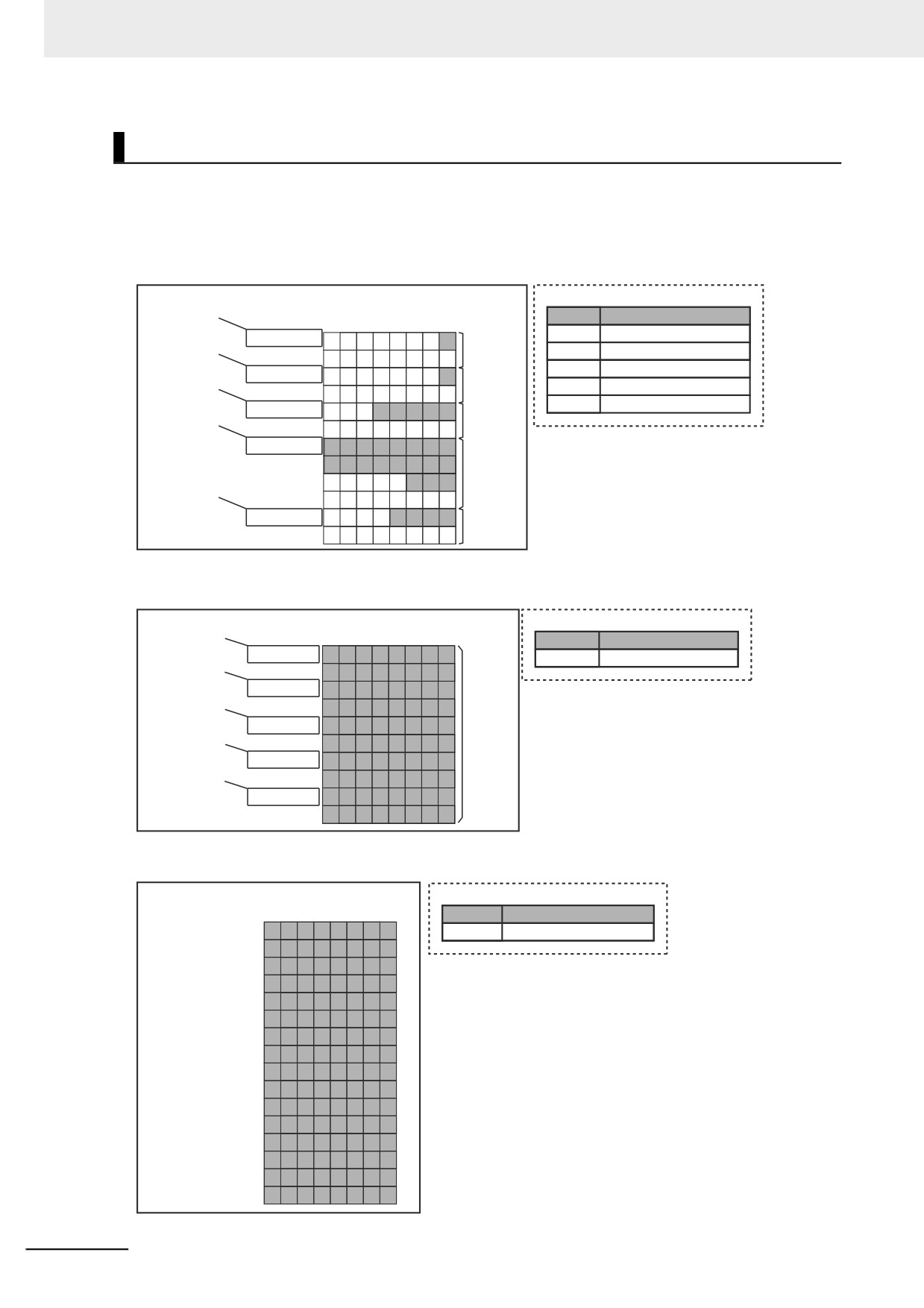
Arrays
A continuous section of memory is allocated for the elements of the array based on the data size of the
data type of the array variable. The alignment of an array is the same as alignment of the data type of
the elements.
Example: Continuous variables in the following order: two BOOL variable, one BOOL array with five
elements, one BOOL array with 19 elements, and one BOOL array with four elements
First byte +
Variable Table
Memory
(integer multiple of 2)
Name
Data type
Bytes
First byte +
A
BOOL
First byte
Variable A,
(integer multiple of 2)
First byte + 1
B
BOOL
2 bytes
First byte +
C
ARRAY[1..5]OF BOOL
First byte + 2
Variable B,
(integer multiple of 2)
First byte + 3
D
ARRAY[0..18]OF BOOL
2 bytes
First byte +
E
ARRAY[5..8]OF BOOL
First byte + 4
Variable C,
(integer multiple of 2)
First byte + 5
2 bytes
First byte + 6
First byte + 7
Variable D,
First byte +
First byte + 8
4 bytes
(integer multiple of 2)
First byte + 9
First byte + 10
Variable E,
First byte + 11
2 bytes
Example: INT array with five elements
First byte +
Memory
Variable Table
(integer multiple of 2)
Bytes
Name
Data type
First byte +
A[0]
First byte
Variable A
ARRAY[0..4] OF INT
(integer multiple of 2)
First byte + 1
First byte +
A[1]
First byte + 2
(integer multiple of 2)
First byte + 3
Variable A,
First byte +
A[2]
First byte + 4
10 bytes
(integer multiple of 2)
First byte + 5
First byte +
A[3]
First byte + 6
(integer multiple of 2)
First byte + 7
A[4]
First byte + 8
First byte + 9
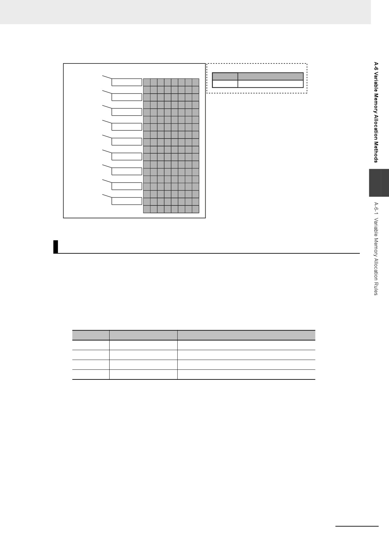
Example: BYTE array with four elements for each dimension with two-dimensional array
Memory
Variable Table
Bytes
Name
Data type
A[0, 0]
First byte
Variable A
ARRAY[0..3, 0..3] OF BYTE
A[0, 1]
First byte + 1
A[0, 2]
First byte + 2
A[0, 3]
First byte + 3
A[1, 0]
First byte + 4
A[1, 1]
First byte + 5
A[1, 2]
First byte + 6
A[1, 3]
First byte + 7
A[2, 0]
First byte + 8
A[2, 1]
First byte + 9
A[2, 2]
First byte + 10
A[2, 3]
First byte + 11
A[3, 0]
First byte + 12
A[3, 1]
First byte + 13
A[3, 2]
First byte + 14
A[3, 3] First byte + 15
A-98
Appendices
Example: WORD array with three elements for each dimension with two-dimensional array
First byte +
Memory
Variable Table
(integer multiple of 2)
Bytes
Name
Data type
First byte +
B[0, 0]
First byte
Variable B
ARRAY[0..2, 0..2] OF WORD
(integer multiple of 2) First byte + 1
First byte +
B[0, 1]
First byte + 2
(integer multiple of 2) First byte + 3
First byte +
B[0, 2]
First byte + 4
(integer multiple of 2)
First byte + 5
First byte +
B[1, 0]
First byte + 6
(integer multiple of 2)
First byte + 7
First byte +
B[1, 1]
First byte + 8
(integer multiple of 2)
First byte + 9
First byte +
B[1, 2]
First byte + 10
(integer multiple of 2)
First byte + 11
First byte +
First byte + 12
B[2, 0]
(integer multiple of 2)
First byte + 13
A
First byte +
First byte + 14
B[2, 1]
(integer multiple of 2)
First byte + 15
B[2, 2]
First byte + 16
First byte + 17
Structures
For a structure variable, the members are located in memory in the order that they are declared. Each
member is located at an integer multiple of the alignment of the data type of the member. Therefore,
there can be unused memory between members or at the end of members. The alignment of a struc-
ture is the largest alignment of all of the members. The amount of memory that is allocated is the inte-
gral multiple of the alignment that is larger than the total amount of memory that is allocated when the
members are arranged in order at integral multiples of the alignment of the data types of the members.
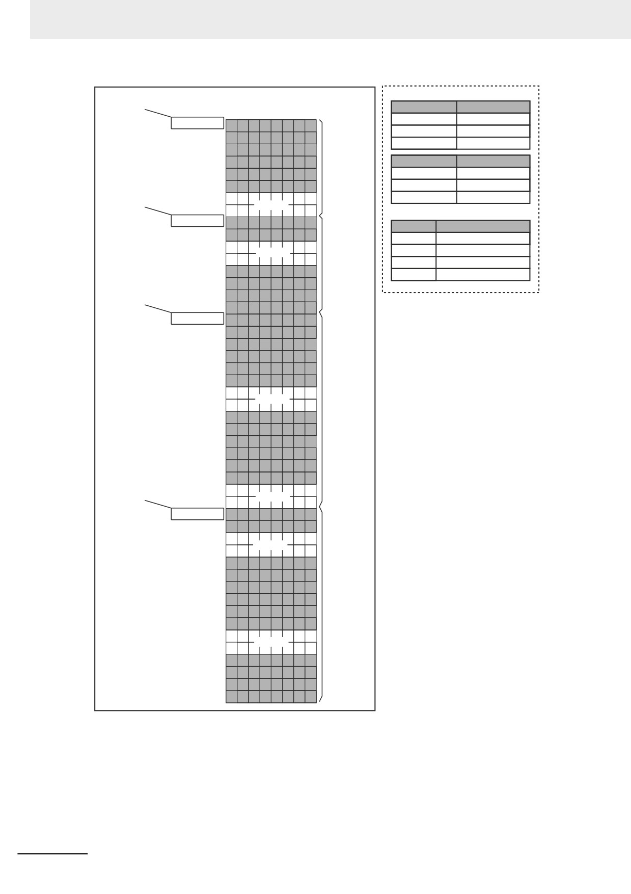
Example: The alignments and the amounts of memory that are allocated for the four variable declara-
tions given in the following figure are given in the following table.
Variable
Alignment [bytes]
Amount of memory that is allocated [bytes]
A
4
8
B
4
8
C
4
16
D
4
16
A-99
Appendices
First byte +
Data Type Definitions
Memory
(integer multiple of 4)
Name
Data type
Bytes
Structure STR_A
STRUCT
A.a
First byte
a
DINT
First byte + 1
b
INT
First byte + 2
First byte + 3
Variable A,
Name
Data type
A.b
First byte + 4
8 bytes
Structure STR_B
STRUCT
First byte + 5
c
INT
First byte +
First byte + 6
d
DINT
(integer multiple of 4)
Not used.
First byte + 7
Variable Table
B.c
First byte + 8
Name
Data type
First byte + 9
Variable A
Structure STR_A
First byte + 10
Variable B,
Not used.
Variable B
Structure STR_B
First byte + 11
8 bytes
Variable C
ARRAY[0..1] OF STR_A
B.d
First byte + 12
Variable D
ARRAY[0..1] OF STR_B
First byte + 13
First byte +
First byte + 14
(integer multiple of 4)
First byte + 15
C[0].a
First byte + 16
First byte + 17
First byte + 18
First byte + 19
C[0].b
First byte + 20
First byte + 21
First byte + 22
Variable C,
Not used.
First byte + 23
16 bytes
C[1].a
First byte + 24
First byte + 25
First byte + 26
First byte + 27
C[1].b
First byte + 28
First byte + 29
First byte +
First byte + 30
(integer multiple of 4)
Not used.
First byte + 31
D[0].c
First byte + 32
First byte + 33
First byte + 34
Not used.
First byte + 35
D[0].d
First byte + 36
First byte + 37
First byte + 38
Variable D,
First byte + 39
16 bytes
D[1].c
First byte + 40
First byte + 41
First byte + 42
Not used.
First byte + 43
D[1].d
First byte + 44
First byte + 45
First byte + 46
First byte + 47
A-100
Appendices
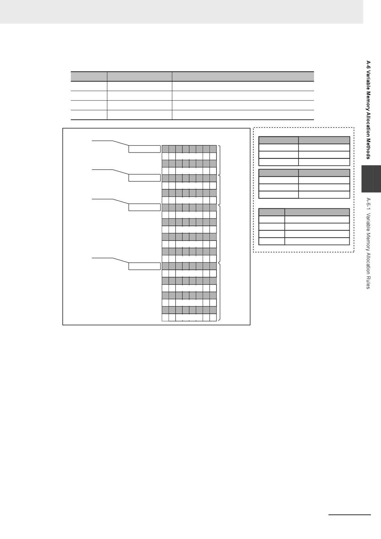
Example: The alignments and the amounts of memory that are allocated for the four variable declara-
tions given in the following figure are given in the following table.
Variable
Alignment [bytes]
Amount of memory that is allocated [bytes]
E
2
4
F
2
4
G
2
8
H
2
8
Data Type Definitions
Memory
First byte +
Bytes
Name
Data type
(integer multiple of 2)
E.a[0] to E.a[7]
First byte
Structure STR_C
STRUCT
First byte + 1
Not used.
a
ARRAY[0..7] OF BOOL
Variable E,
E.b
First byte + 2
b
BYTE
4 bytes
First byte +
First byte + 3
Not used.
(integer multiple of 2)
Name
Data type
F.c
First byte + 4
Structure STR_D
STRUCT
A
First byte + 5
Not used.
Variable F,
c
BYTE
F.d[0] to F.d[7]
First byte + 6
4 bytes
d
ARRAY[0..7] OF BOOL
First byte +
First byte + 7
Not used.
(integer multiple of 2)
Variable Table
G[0].a[0] to G[0].a[7]
First byte + 8
Name
Data type
First byte + 9
Not used.
Variable E
Structure STR_C
G[0].b
First byte + 10
Variable F
Structure STR_D
First byte + 11
Not used.
Variable G,
Variable G
ARRAY[0..1] OF STR_C
G[1].a[0] to G[1].a[7]
First byte + 12
8 bytes
Variable H
ARRAY[0..1] OF STR_D
First byte + 13
Not used.
G[1].b
First byte + 14
First byte +
First byte + 15
Not used.
(integer multiple of 2)
H[0].c
First byte + 16
First byte + 17
Not used.
H[0].d[0] to H[0].d[7]
First byte + 18
First byte + 19
Not used.
Variable H,
H[1].c
First byte + 20
8 bytes
First byte + 21
Not used.
H[1].d[0] to H[1].d[7]
First byte + 22
First byte + 23
Not used.
A-101
Appendices
Unions
For a union variable, the members overlap in the same memory locations. The alignment of a union is
largest alignment of all of the members. The amount of memory that is allocated is the largest amount
of memory that is allocated for any of the members.
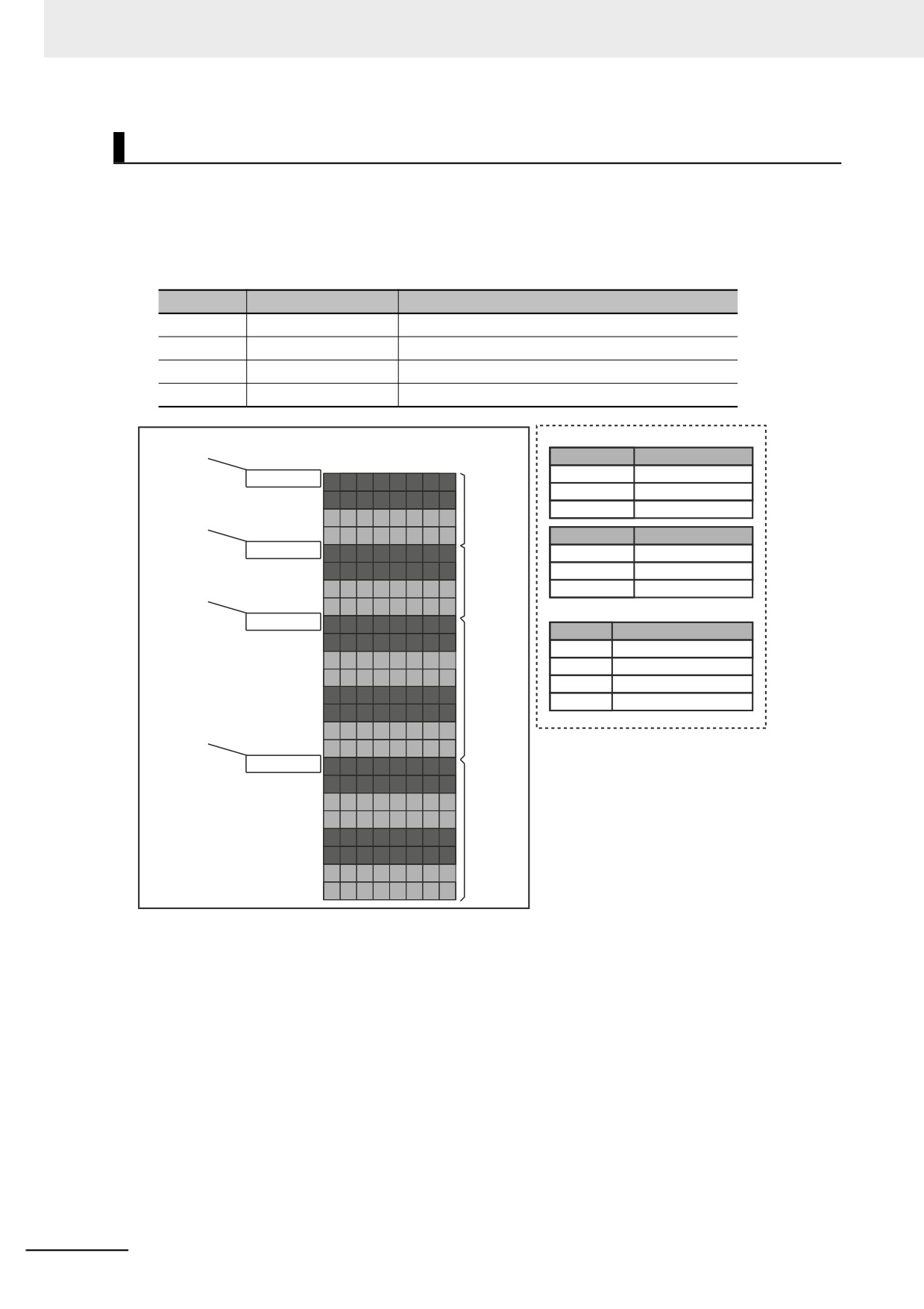
Example: The alignments and the amounts of memory that are allocated for the four variable declara-
tions given in the following figure are given in the following table.
Variable
Alignment [bytes]
Amount of memory that is allocated [bytes]
A
4
4
B
4
4
C
4
8
D
4
8
First byte +
Data Type Definitions
Memory
(integer multiple of 4)
Name
Data type
Bytes
Union UNI_A
UNION
A.a A.b
First byte
First byte + 1
a
DWORD
First byte +
Variable A,
b
WORD
First byte + 2
(integer multiple of 4)
4 bytes
First byte + 3
Name
Data type
B.c B.d
First byte + 4
Union UNI_B
UNION
First byte + 5
c
WORD
First byte +
Variable B,
First byte + 6
d
DWORD
(integer multiple of 4)
4 bytes
First byte + 7
Variable Table
C[0].a C[0].b
First byte + 8
Name
Data type
First byte + 9
Variable A
Union UNI_A
First byte + 10
Variable C,
Variable B
Union UNI_B
First byte + 11
8 bytes
Variable C
ARRAY[0..1] OF UNI_A
C[1].a C[1].b
First byte + 12
Variable D
ARRAY[0..1] OF UNI_B
First byte + 13
First byte +
First byte + 14
(integer multiple of 4)
First byte + 15
D[0].c D[0].d
First byte + 16
First byte + 17
First byte + 18
Variable D,
First byte + 19
8 bytes
D[1].c D[1].d
First byte + 20
First byte + 21
First byte + 22
First byte + 23
A-102
Appendices
A-6-2
Important Case Examples
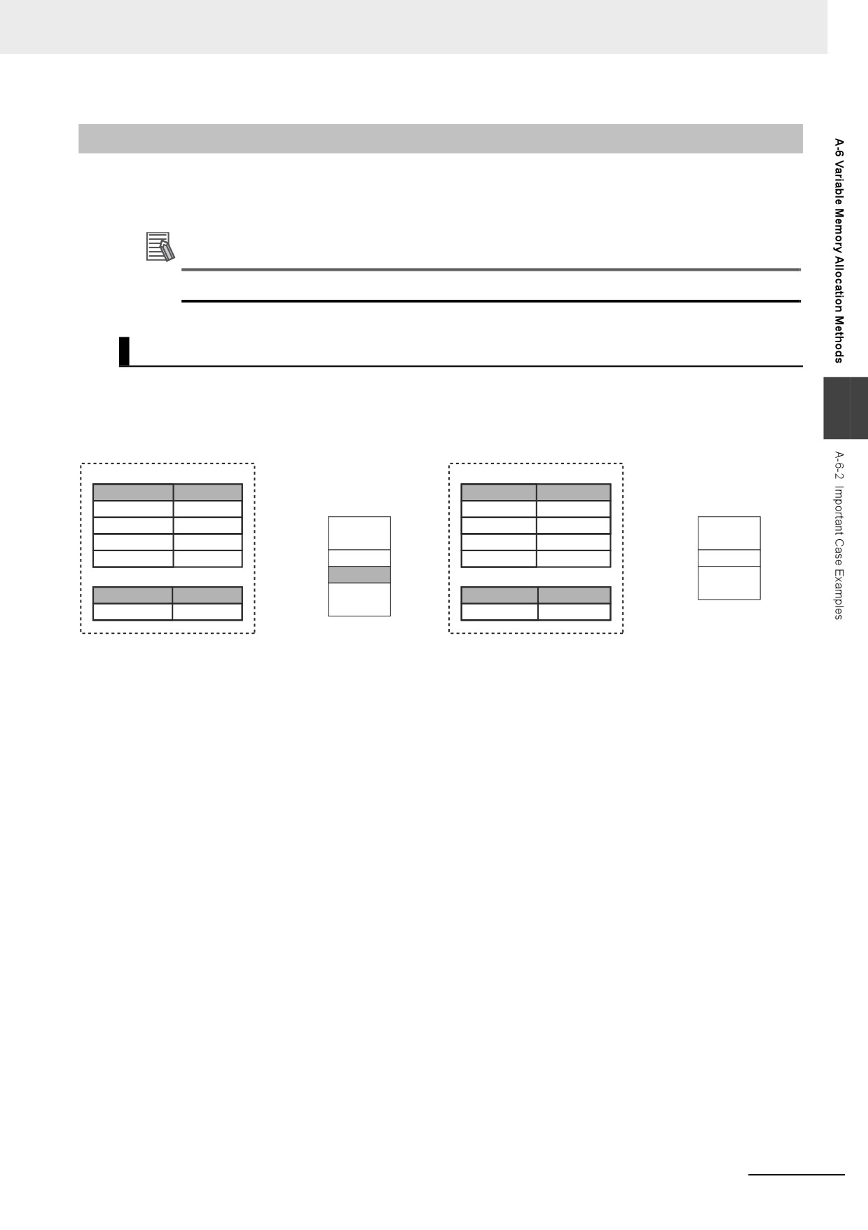
When you exchange structure variable data between an NY-series Controller and a remote device, you
must align the memory configuration of the structure variable members with those of the remote device.
This section describes what to do in either the NY-series Controller or in the remote device.
Additional Information
This is not necessary when you exchange data between NY-series Controllers.
Aligning the Memory Configuration with a Remote Device
There are two methods that you can use to align the memory configuration with a remote device.
For example, the differences in the memory configuration for structure variables between an NY-
A
series Controller and a CJ-series CPU Unit are shown below.
This section describes how to align the memory configuration for these Units.
Data Type Definitions
Data Type Definitions
Name
Data type
NY-series Structure Variable NY_X
Name
Data type
CJ-series Structure Variable CJ_X
Structure Y
STRUCT
Bytes
Structure Y
STRUCT
Bytes
a
DINT
First byte
a
a
DINT
First byte
a
b
INT
b
INT
c
DINT
First byte + 4
b
c
DINT
First byte + 4
b
Variable Table
First byte + 6
Not used.
Variable Table
First byte + 6
c
Name
Data type
First byte + 8
c
Name
Data type
Variable NY_X
Structure Y
Variable CJ_X
Structure Y
z Method 1: Changing the Memory Configuration of the Structure Variable in
the NY-series Controller
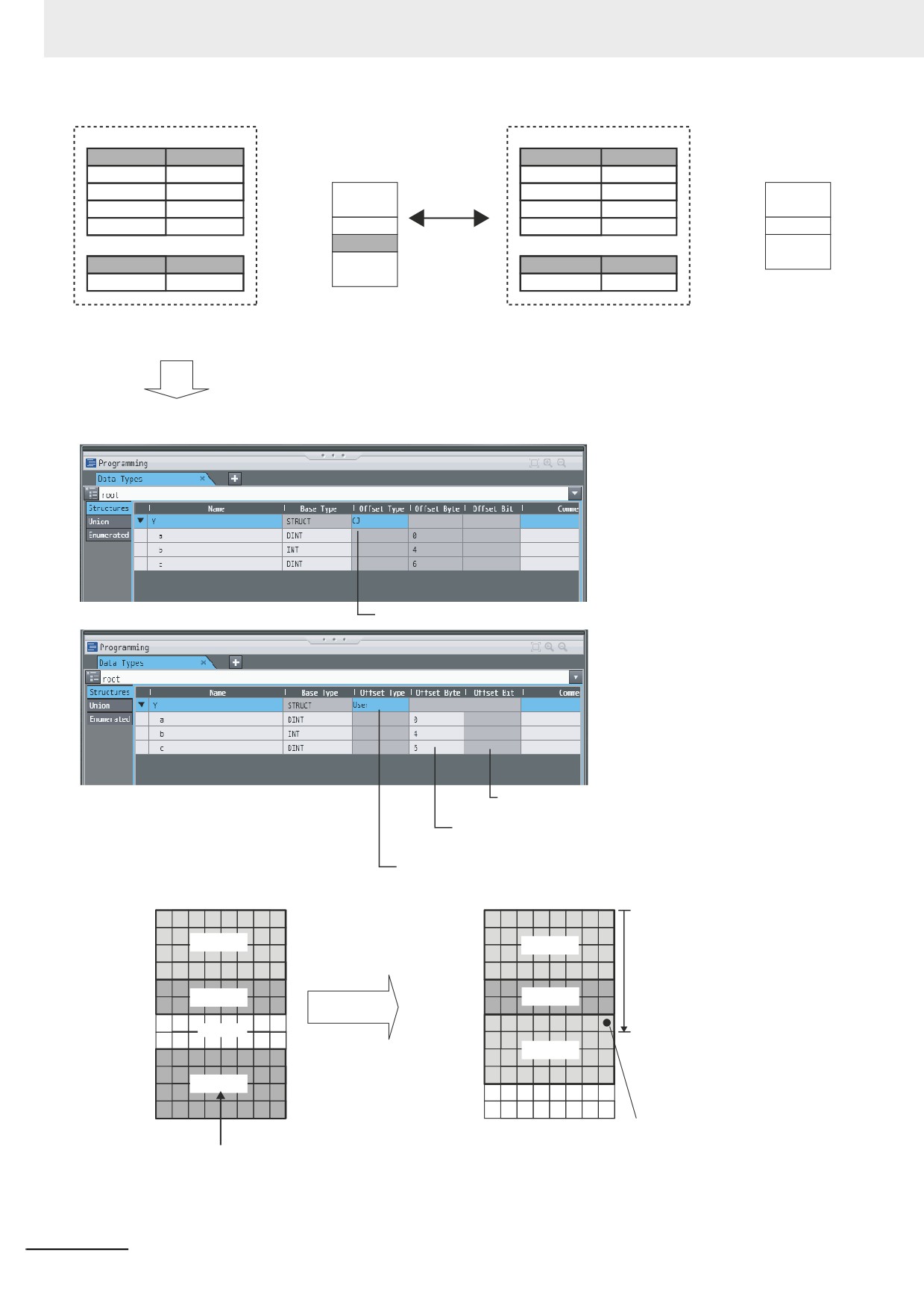
With an NY-series Controller, you can specify member offsets to change the memory configuration
of the members of a structure variable. You can change the memory configuration of the members
of a structure variable in the NY-series Controller so that it is the same as the memory configuration
in a remote device that the NY-series Controller will communicate with. Specify the member offsets
for a structure variable when you register the structure data type.
To communicate with a CJ-series CPU Unit, you can set the offset type to CJ to automatically use
the CJ-series memory structure. You can set the offset type to User to freely set your own offsets.
If you change the memory configuration of a structure variable by setting offsets, you must make the
same changes for the same structure variable in other NY-series Controllers on the network.
Refer to the Sysmac Studio Version 1 Operation Manual (Cat. No W504-E1-03 or later) for the pro-
cedure to change the memory configuration of a structure variable.
Example: The following example shows how the memory configuration of the structure variable in
the CJ-series CPU Unit is changed to match the memory configuration of the structure variable in
the NY-series Controller.
A-103
Appendices
Data Type Definitions
NY-series Structure
Data Type Definitions
CJ-series Structure
Name
Data type
Variable NY_X
Name
Data type
Variable CJ_X
Bytes
Bytes
Structure Y
STRUCT
Structure Y
STRUCT
a
DINT
First byte
a
a
DINT
First byte
a
b
INT
b
INT
c
DINT
First byte + 4
b
c
DINT
First byte + 4
b
Communications is
Variable Table
First byte + 6
Not used.
Variable Table
First byte + 6
c
not possible
First byte + 8
c
Name
Data type
because the memory
Name
Data type
configuration is not
Variable NY_X
Structure Y
Variable CJ_X
Structure Y
the same.
To align the memory configurations in the NY-series Controller and CJ-series CPU Unit, offsets are set in the Sysmac Studio.
Here, the following offsets are set for member c of data type Y of the structure variable NY_X.
(1) Offset type is set to CJ.
(3) Bit Offset
Set the location of the first bit of the member
(2) Byte Offset
Set the location of the first byte of the
member from the beginning of the structure
(1) Offset Type
Specify User.
Memory Bytes
Memory Bytes
First byte
First byte
(2) Byte Offset
First byte + 1
First byte + 1
Variable c starts from the 6th
Variable a
Variable a
First byte + 2
First byte + 2
byte from the start of the
structure.
First byte + 3
First byte + 3
First byte + 4
First byte + 4
Variable b
Variable b
First byte + 5
First byte + 5
First byte + 6
First byte + 6
Not used.
First byte + 7
First byte + 7
Variable c
First byte + 8
The location of
First byte + 8
variable c changes
First byte + 9
First byte + 9
Variable c
according to the
First byte + 10
First byte + 10
offsets.
First byte + 11
First byte + 11
(3) Bit Offset
Variable c starts from the
Set a byte offset of 6 and a bit offset
0th bit from the start of the
of 0 (no offset) for variable c.
A-104
Appendices
z Method 2: Changing the Memory Configuration of the Structure Variable in
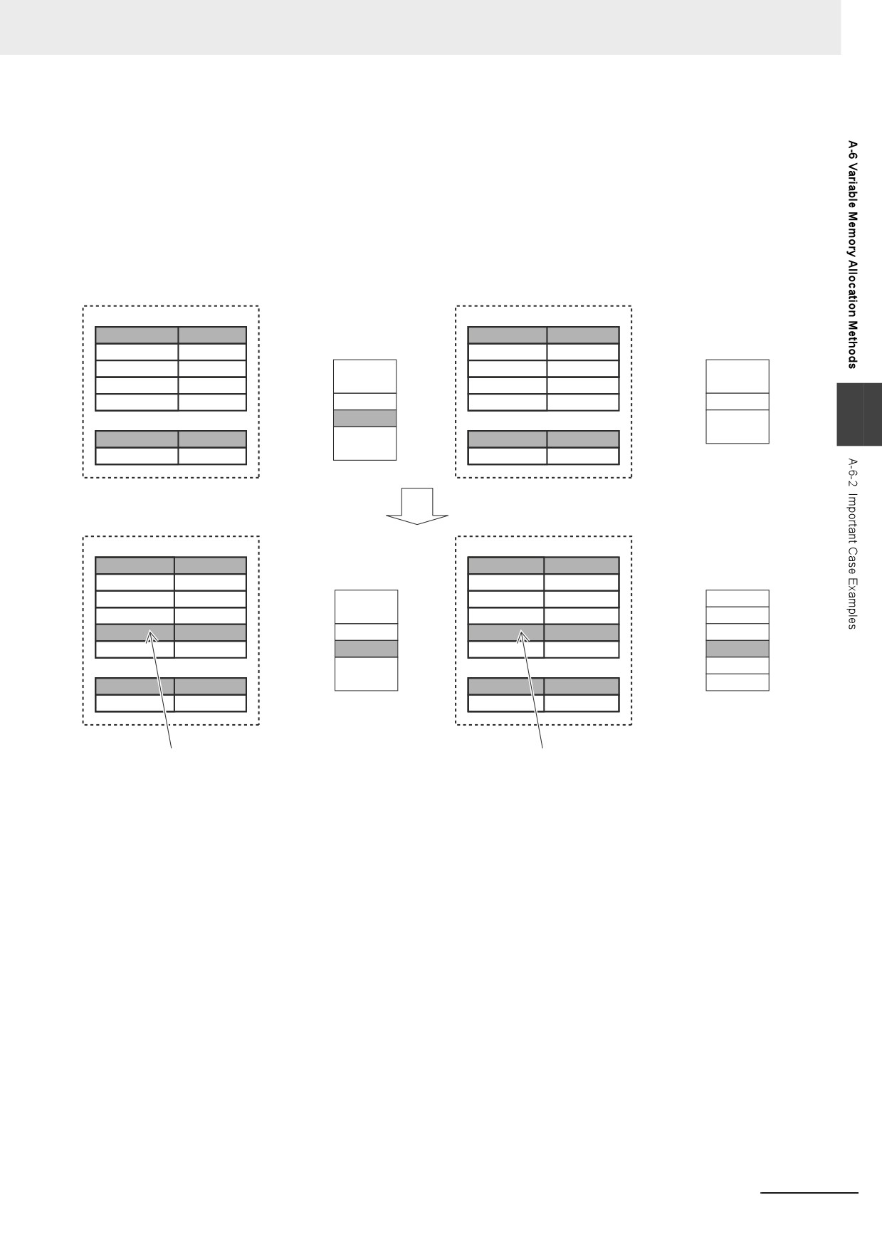
the Remote Device
You can insert a member into the structure variable of the remote device to change it to match the
memory configuration of the structure variable in the NY-series Controllers. Both the memory config-
uration and the data types must be the same between the two structure variables. You therefore
need to create the same members in both the remote device and the NY-series Controllers.
Example: The following example shows how the memory configuration of the structure variable in
the CJ-series CPU Unit is changed to match the memory configuration of the structure variable in
the NY-series Controllers.
Data Type Definitions
Data Type Definitions
NY-series Structure Variable NY_X
CJ-series Structure Variable CJ_X
Name
Data type
Name
Data type
Structure Y
STRUCT
Bytes
Structure Y
STRUCT
Bytes
a
DINT
First byte
a
a
DINT
First byte
a
b
INT
b
INT
c
DINT
First byte + 4
b
c
DINT
First byte + 4
b
Not used.
A
Variable Table
First byte + 6
Variable Table
First byte + 6
c
Name
Data type
First byte + 8
Name
Data type
c
Variable NY_X
Structure Y
Variable CJ_X
Structure Y
Make the following changes to align the memory configurations
in the NY-series Controller and CJ-series CPU Unit.
Data Type Definitions
Data Type Definitions
Name
Data type
NY-series Structure Variable NY_X
Name
Data type
CJ-series Structure Variable CJ_X
Structure Y
STRUCT
Bytes
Structure Y
STRUCT
Bytes
a
DINT
First byte
a
a
DINT
First byte
a
b
INT
b
INT
b2
INT
First byte + 4
b
b2
INT
First byte + 4
b
c
DINT
First byte + 6
b2
c
DINT
First byte + 6
b2
Variable Table
First byte + 8
c
Variable Table
First byte + 8
c
Name
Data type
Name
Data type
Variable NY_X
Structure Y
Variable CJ_X
Structure Y
(2) Add the dummy variable b2 that you created in the
(1) Add a dummy member variable b2 that matches the
CJ-series CPU Unit to the NY-series Controller as well.
unused memory location on the NY-series Controller.
A-105
Appendices
A-7
Registering a Symbol Table on the
CX-Designer
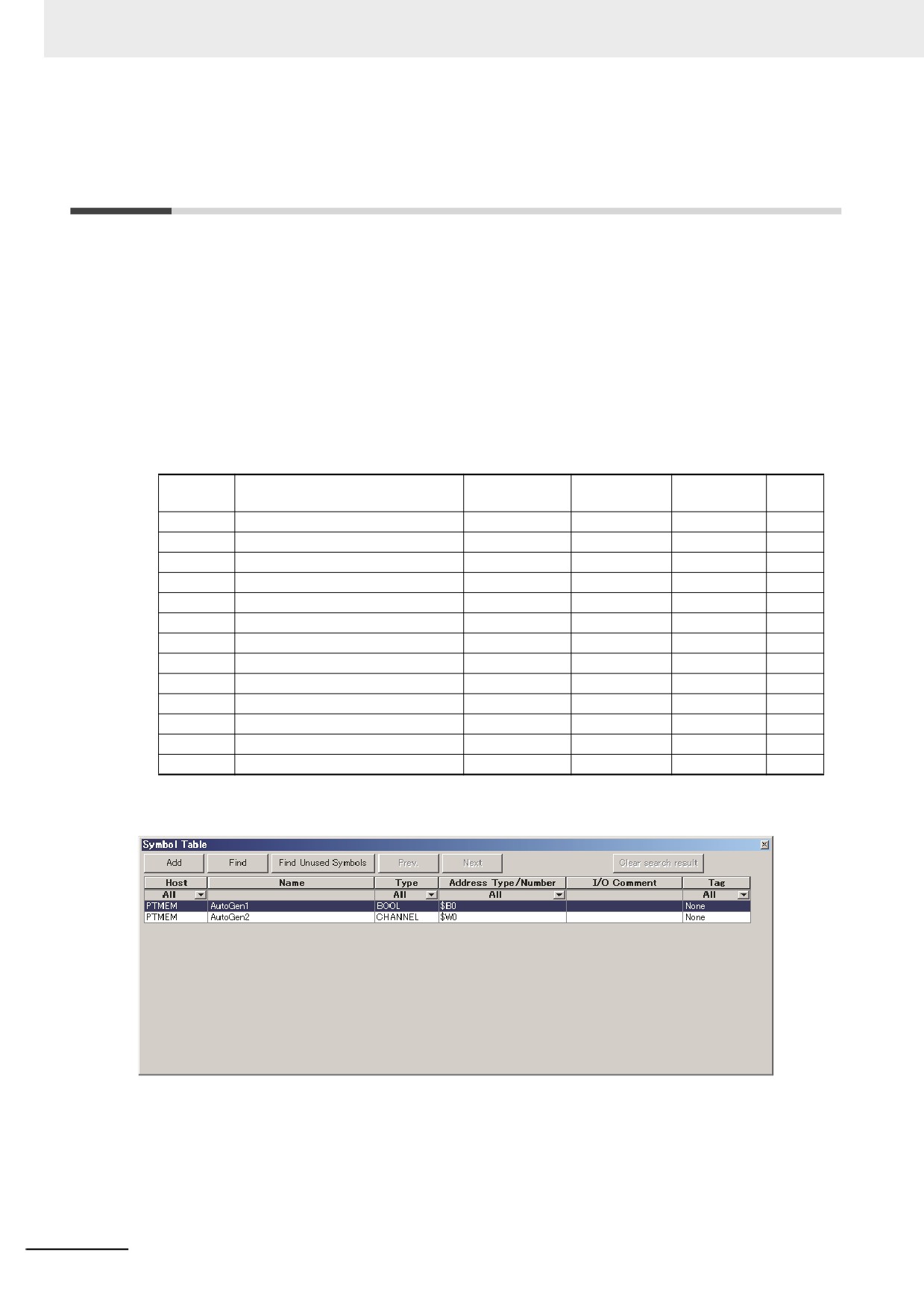
When you connect the NY-series Controller to an NS-series PT, you can use variables on the CX-
Designer to set addresses for the functional objects. The variables are managed in a symbol table. This
section shows how to copy a table of variables from a Microsoft Excel spreadsheet to register them all
at the same time in a symbol table. Refer to the CX-Designer User’s Manual (Cat. No. V099) for
detailed information on the CX-Designer.
1 Use the following format to create a table of variables in a Microsoft Excel spreadsheet.
You must use the same number and arrangement of columns as in the following format. Do not
omit any columns even if they are empty, like the Address type/address and I/O comment col-
umns that are shown below.
Address
I/O com-
Host
Name
Type
Tag
type/address
ment
HOST3
_Card1BkupCmd.ExecBkup
BOOL
TRUE
HOST3
_Card1BkupCmd.CancelBkup
BOOL
TRUE
HOST3
_Card1BkupCmd.ExecVefy
BOOL
TRUE
HOST3
_Card1BkupCmd.CancelVefy
BOOL
TRUE
HOST3
_Card1BkupCmd.DirName
STRING(64)
TRUE
HOST3
_Card1BkupSta.Done
BOOL
TRUE
HOST3
_Card1BkupSta.Active
BOOL
TRUE
HOST3
_Card1BkupSta.Err
BOOL
TRUE
HOST3
_Card1VefySta.Done
BOOL
TRUE
HOST3
_Card1VefySta.Active
BOOL
TRUE
HOST3
_Card1VefySta.VefyRslt
BOOL
TRUE
HOST3
_Card1VefySta.Err
BOOL
TRUE
HOST3
_BackupBusy
BOOL
TRUE
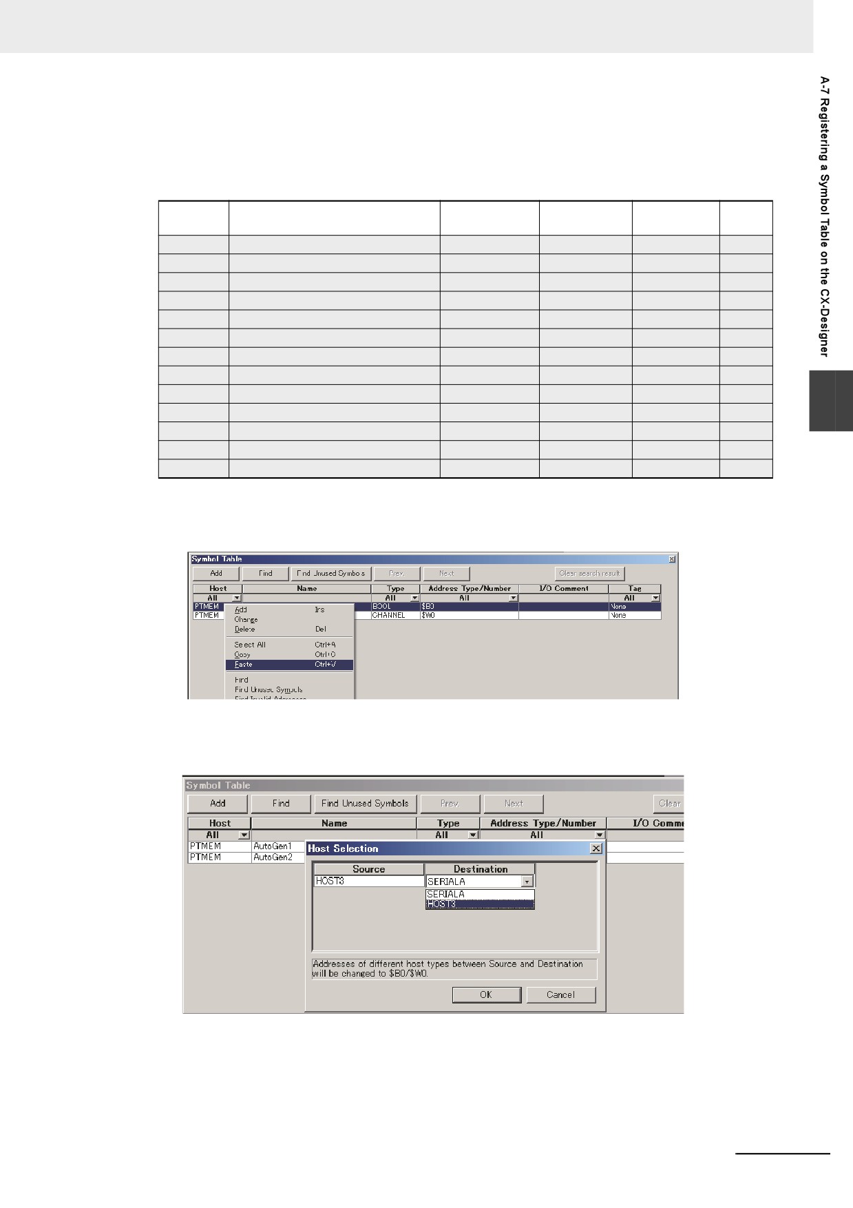
2 Start the CX-Designer and open the Symbol Table Dialog Box.
A-106
Appendices
3 Copy the shaded portion of the Microsoft Excel spreadsheet.
Always copy all of the columns that are shown below.
Address
I/O com-
Host
Name
Type
Tag
type/address
ment
HOST3
_Card1BkupCmd.ExecBkup
BOOL
TRUE
HOST3
_Card1BkupCmd.CancelBkup
BOOL
TRUE
HOST3
_Card1BkupCmd.ExecVefy
BOOL
TRUE
HOST3
_Card1BkupCmd.CancelVefy
BOOL
TRUE
HOST3
_Card1BkupCmd.DirName
STRING(64)
TRUE
HOST3
_Card1BkupSta.Done
BOOL
TRUE
HOST3
_Card1BkupSta.Active
BOOL
TRUE
HOST3
_Card1BkupSta.Err
BOOL
TRUE
HOST3
_Card1VefySta.Done
BOOL
TRUE
A
HOST3
_Card1VefySta.Active
BOOL
TRUE
HOST3
_Card1VefySta.VefyRslt
BOOL
TRUE
HOST3
_Card1VefySta.Err
BOOL
TRUE
HOST3
_BackupBusy
BOOL
TRUE
4 Right-click in the Symbol Table Dialog Box in the CX-Designer and select Paste from the
menu.
5 In the Host Selection Dialog Box on the CX-Designer, select the NY-series Controller host
and then click the OK Button.
A-107
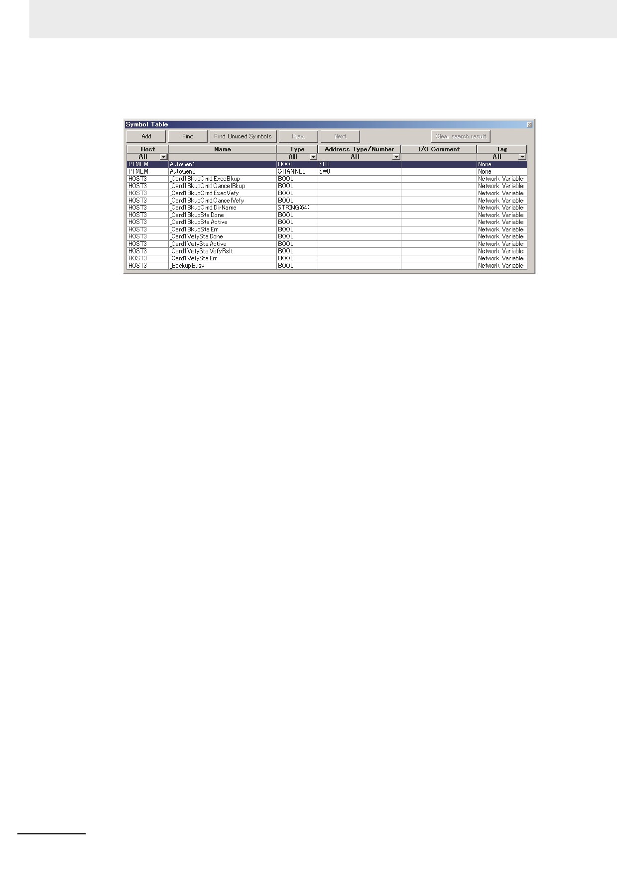
Appendices
The variables are registered in the Symbol Table Dialog Box of the CX-Designer.
A-108
Appendices
A-8
Enable/Disable EtherCAT Slaves and
Axes
You can enable and disable EtherCAT slaves and axes using programming instructions. You can use
this for the following types of applications.
• Managing more than one machine with different EtherCAT slave configurations and axis composi-
tions with one project on the Sysmac Studio.
• Leaving one production line running while you change the EtherCAT slave configuration or axis com-
position of another line.
This section describes the instructions and system-defined variables that are used and provides some
application examples.
A
A-8-1
Project Settings When Using EtherCAT Slaves and Axes
When you turn ON the power supply or download the project, disable in advance any EtherCAT slaves
that may not be installed in the EtherCAT network. Also, set any axes for those EtherCAT slaves to
unused axes. If any EtherCAT slaves that are not installed on the EtherCAT network are enabled or if
any of their axes are set to used axes, an error will occur when operation is started.
Additional Information
• You can also enable and disable EtherCAT slaves in the following Sysmac Studio settings:
Configurations and Setup − EtherCAT − Network Configuration − Enable/Disable Set-
tings. If you use the Sysmac Studio settings, however, you would have to use the Sysmac
Studio to change the settings every time or you would have to change the project file depend-
ing on the machine to handle the application that is described later in Application 1: Central-
ized Management of Machines with Different EtherCAT Slave Configuration and Axis
Composition on page A-112.
• You can disable an EtherCAT slave to enable removing it or installing it on the EtherCAT net-
work.
A-8-2
Using Instructions to Enable/Disable EtherCAT Slaves and Axes
You can use instructions in the user program to enable and disable EtherCAT slaves and axes. Sepa-
rate instructions are used to enable and disable EtherCAT slaves and to enable and disable axes. Both
instructions are given in the following table.
Item changed
Instruction
EtherCAT slaves
EC_ChangeEnableSetting (Enable/Disable EtherCAT Slave) instruction
Axes
MC_ChangeAxisUse (Change Axis Use) instruction
EC_ChangeEnableSetting Instruction
The EC_ChangeEnableSetting (Enable/Disable EtherCAT Slave) instruction is used to enable and dis-
able EtherCAT slaves. You can use the EC_ChangeEnableSetting instruction to enable or disable the
EtherCAT slave with the specified node address. If you cycle the power supply to the Controller after
this instruction is executed, the settings will return to the settings from before instruction execution.
Refer to the NY-series Instructions Reference Manual (Cat. No. W560) for the detailed specifications of
the EC_ChangeEnableSetting instruction.
A-109