Omron IPC Machine Controller Industrial Panel PC / Industrial Box PC. Software User’s Manual (Industrial PC Platform NY-series) - page 20
Appendices
MC_ChangeAxisUse Instruction
The MC_ChangeAxisUse (Change Axis Use) instruction is used to enable and disable axes. The
MC_ChangeAxisUse instruction changes the setting of the Axis Use axis parameter of the specified
axis between Used Axis and Unused Axis. If you cycle the power supply to the Controller after this
instruction is executed, the settings will return to the settings from before instruction execution. Refer to
the NY-series Motion Control Instructions Reference Manual (Cat. No. W561) for the detailed specifica-
tions of the MC_ChangeAxisUse instruction.
A-8-3
System-defined Variables That Indicate EtherCAT Slave or Axis
Status
You can check the values of system-defined variables to get the current status of EtherCAT slaves and
axes. The system-defined variables for these are given below.
Accessed status
System-defined variable name
EtherCAT slaves
_EC_DisableSlavTbl[] (Disabled Slave Table)
Axes
_MC_AX[].Cfg.AxEnable (Axis Use)
_EC_DisableSlavTbl[] (Disabled Slave Table)
The _EC_DisableSlavTbl[] (Disabled Slave Table) system-defined variable tells whether each Ether-
CAT slave is currently disabled. The node address is specified for the array subscript. The meanings of
the values in _EC_DisableSlavTbl[] (Disabled Slave Table) are given below.
Value
Meaning
TRUE
The EtherCAT slave with the specified node address is disabled.
FALSE
The EtherCAT slave with the specified node address is enabled.
_MC_AX[].Cfg.AxEnable (Axis Use)
The _MC_AX[].Cfg.AxEnable (Axis Use) system-defined variable tells whether each axis is defined and
whether each axis is used. The axis number is specified for the array subscript. The meanings of the
values in _MC_AX[].Cfg.AxEnable (Axis Use) are given below.
Value
Meaning
0: _mcNoneAxis
The specified axis is an undefined axis.
1: _mcUnusedAxis
The specified axis is an unused axis.
2: _mcUsedAxis
The specified axis is a used axis.
A-8-4
Enabling/Disabling Execution of Program
There are certain programs associated with the EtherCAT slaves and axes, which are enabled or dis-
abled. These associated programs must be enabled or disabled as the EtherCAT slaves and axes are
enabled or disabled. To enable or disable the program, use the following instructions in the user pro-
gram.
Function
Instruction
Enable program
PrgStart instruction
Disable program
PrgStop instruction
A-110
Appendices
Refer to the NY-series Instructions Reference Manual (Cat. No. W560) for the detailed specifications of
the PrgStart instruction and PrgStop instruction.
Precautions for Correct Use
When you want to disable the program, first disable the EtherCAT slave and axis which the pro-
gram is associated with, and then disable the program.
A-8-5
Checking Enabled/Disabled Program
You can use the PrgStatus instruction to check the program is enabled or disabled that is associated
with the EtherCAT slave and axis that are enabled and disabled.
Refer to the NY-series Instructions Reference Manual (Cat. No. W560) for the detailed specifications of
the PrgStatus instruction.
A
A-8-6
Settings with the Sysmac Studio
You can also enable/disable the EtherCAT slaves and axes and set to enable/disable the program at
the start of operation using the Sysmac Studio. Some applications require that EtherCAT slave status,
axis status and program status at the start of operation are set in advance with the Sysmac Studio.
Enabling/Disabling EtherCAT Slaves with Sysmac Studio
Use the following procedure to enable an EtherCAT slave on the Sysmac Studio.
1 Right-click EtherCAT under Configurations and Setup and select Edit from the menu.
The EtherCAT Tab Page is displayed.
2 In the Toolbox, right-click the EtherCAT slave you want to connect and select Insert from the menu.
The selected EtherCAT slave is displayed under the EtherCAT master on the EtherCAT Tab
Page. Also, the Parameter Settings Area for the EtherCAT slave is displayed on the right side of
the EtherCAT Tab Page.
3 Set the value of Enable/Disable Settings to Enabled on the Parameter Settings Area for the
EtherCAT slave.
Enabling/Disabling Axis with Sysmac Studio
Use the following procedure to enable an axis on the Sysmac Studio.
1 Right-click Axis Settings under Configurations and Setup - Motion Control Setup and select
Add - Axis Settings from the menu.
The axis MC_Axis000(0) is added under Axis Settings.
2 Right-click MC_Axis000(0) and select Edit from the menu.
The Axis Basic Settings Display appears.
3 Set Axis Use to Used Axis.
A-111
Appendices
Running/Stopping Program at the Start of Operation with Sysmac
Studio
Use the following procedure to execute a program at the start of operation on the Sysmac Studio.
1 Right-click Task Settings under Configurations and Setup and select Edit from the menu.
The Task Settings Tab Page is displayed.
2 Click the Program Assignment Settings Button.
The Program Assignment Settings Display appears.
3 Set Initial Status of the program to Run on the Program Assignment Settings Display.
A-8-7
Examples of Applications of Enabling/Disabling EtherCAT
Slaves and Axes
This section provides concrete examples of applications in which EtherCAT slaves and axes are
enabled and disabled.
Application 1: Centralized Management of Machines with Different
EtherCAT Slave Configuration and Axis Composition
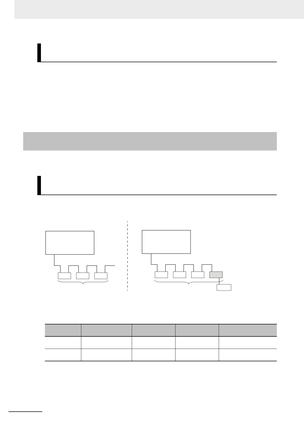
Assume that the EtherCAT slaves and axis compositions for the NY-series Controllers are different for
machines 1 and 2 as shown below. These two machines are centrally managed using one Sysmac Studio proj-
ect.
EtherCAT Slave Configuration and
EtherCAT Slave Configuration and
Axis Composition of Machine 1
Axis Composition of Machine 2
Controller
Controller
EtherCAT
EtherCAT
A
B
C
A
B
C
D
EtherCAT slaves, axes
EtherCAT slaves, axes
Sensor
In the Sysmac Studio project, an EtherCAT Slave Configuration is created for all four EtherCAT slaves
and axes in A, B, C, and D in the figure. Then, on the Sysmac Studio, you set the EtherCAT slave
enable/disable settings, Axis Use parameter settings, and the associated program run/stop status at
the start of operation according to machine 1, as shown in the following table.
EtherCAT
Installed in
Enable/disable
Axis Use
Associated programs
slave
EtherCAT network
setting
parameter setting
A, B, and C
Installed.
Enabled.
Used Axis
Run at the start of opera-
tion.
D
Not installed.
Disabled.
Unused Axis
Stop at the start of opera-
tion.
A-112
Appendices
To make changes for machine 2, you use instructions to change the EtherCAT slave enable/disable settings, Axis
Use parameter settings, and the associated program enable/disable settings as shown in the following table.
EtherCAT
Installed in
Enable/disable
Axis Use
Associated programs
slave
EtherCAT network
setting
parameter setting
A, B, and C
Installed.
Enabled.
Used Axis
Executed.
D
Installed.
Enabled.
Used Axis
Executed.
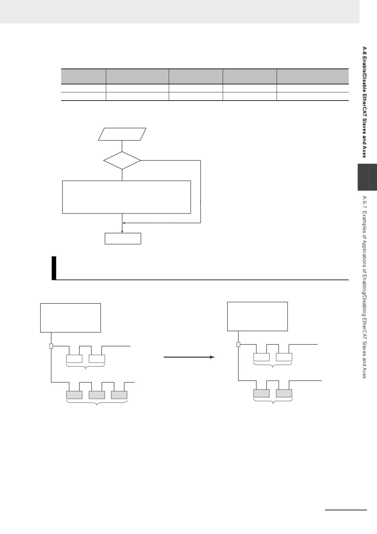
The user program algorithm is shown in the following figure. A signal is input to the Controller from an
external device to specify whether machine 1 or machine 2 is operated.
External signal input.
Yes
Machine 1?
No
A
The EC_ChangeEnableSetting instruction is executed to enable
the slave for node D and the MC_ChangeAxisUse instruction is
executed to change the axis for node D to a used axis.
The program associated with node D is executed by the
PrgStart instruction.
Operation started.
Application 2: Changing the EtherCAT Slave Configuration and Axis
Composition during Operation
In the following figure, production line 1 is left running while the EtherCAT slaves and axis composition
on production line 2 are changed.
Controller
Controller
Production line 1 is left running
EtherCAT
while the EtherCAT slaves and
EtherCAT
axis composition on production
line 2 are changed.
A
B
Production line 1
A
B
Production line 1
EtherCAT slaves, axes
EtherCAT slaves, axes
Production line 2
C
D
E
Production line 2
F
G
EtherCAT slaves, axes
EtherCAT slaves, axes
A-113
Appendices
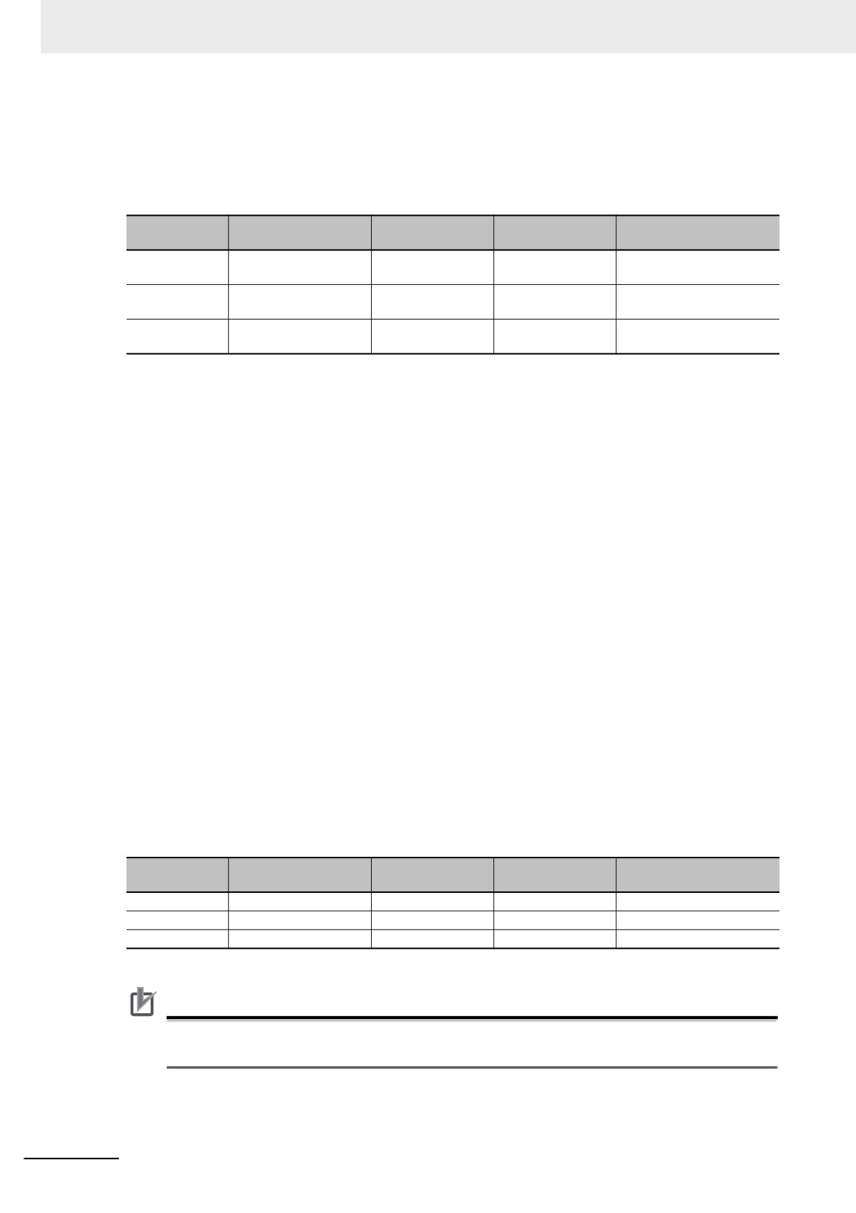
In the Sysmac Studio project, an EtherCAT slave configuration is created for all seven EtherCAT slaves
and axes in A to G in the figure.
On the Sysmac Studio, set the EtherCAT slave enable/disable settings, Axis Use parameter settings,
and the associated program run/stop status at the start of operation for nodes A to G as shown in the
following table. These are the settings for the configuration before change.
EtherCAT
Installed in
Enable/disable
Axis Use
Associated programs
slave
EtherCAT network
setting
parameter setting
A and B
Installed.
Enabled.
Used Axis
Run at the start of opera-
tion.
C, E, and D
Installed.
Enabled.
Used Axis
Run at the start of opera-
tion.
F and G
Not installed.
Disabled.
Unused Axis
Stop at the start of opera-
tion.
The following procedure is used to change the EtherCAT slaves and axes that are used from C, D, E to
F and G.
1 Stop production line 4.
2 Use the MC_ChangeAxisUse instruction to set the Axis Use parameters for C, D, and E to
Unused Axis.
3 Use the EC_ChangeEnableSetting instruction to disable the settings for EtherCAT slaves C, D,
and E.
4 Use the PrgStop instruction to disable the programs associated with C, D and E.
5 Remove EtherCAT slaves C, D, and E from production line 4.
6 Install EtherCAT slaves F and G on production line 4.
7 Use the EC_ChangeEnableSetting instruction to enable the settings for EtherCAT slaves F and
G.
8 Use the MC_ChangeAxisUse instruction to set the Axis Use parameters for F and G to Used
Axis.
9 Use the PrgStart instruction to enable the programs associated with F and G.
10 Start production line 4 again.
As the result of the above steps, the EtherCAT slave enable/disable settings, Axis Use parameter set-
tings, and the associated programs enable/disable settings are changed as shown below.
EtherCAT
Installed in
Enable/disable
Axis Use
Associated programs
slave
EtherCAT network
setting
parameter setting
A and B
Installed.
Enabled.
Used Axis
Enabled.
C, E, and D
Not installed.
Disabled.
Unused Axis
Disabled.
F and G
Installed.
Enabled.
Used Axis
Enabled.
Precautions for Correct Use
When you want to disable the program, first disable the EtherCAT slave and axis which the pro-
gram is associated with, and then disable the program.
A-114
Appendices
A-9
Size Restrictions for the User Program
There are size restrictions for the user program due to the limitations of the memory capacity in the
Controller and other factors. If you exceed these restrictions, errors will occur during operation. This
section describes each of the size restrictions of a user program that is created in a Controller.
You can check the approximate sizes of the user program and variables with the memory display func-
tions of the Sysmac Studio.
Be careful not to exceed these restrictions when you create the user program. The restrictions that are
given in this section, however, are only reference values for use as guidelines. We recommend that you
ensure ample leeway for the restrictions to allow for the possibility of future user program expansion as
well as for other reasons.
Precautions for Correct Use
A
Errors can occur during online editing even if the user program size restrictions are not
exceeded. This is because even if you change the user program with online editing, other data
that is allocated in the memory of the Controller may remain. If errors occur, change the Control-
ler to PROGRAM mode and transfer the user program to the Controller again to reset the errors.
A-9-1
User Program Object Restrictions
This section describes the restrictions to user program objects. There are restrictions for the following
objects.
• POU
• Variables
• Data type definitions
• Constants (literals)
POU Restrictions
There are restrictions both on POU definitions and POU instances.
z POU Definition Restrictions
POU definitions are subject to the following restrictions.
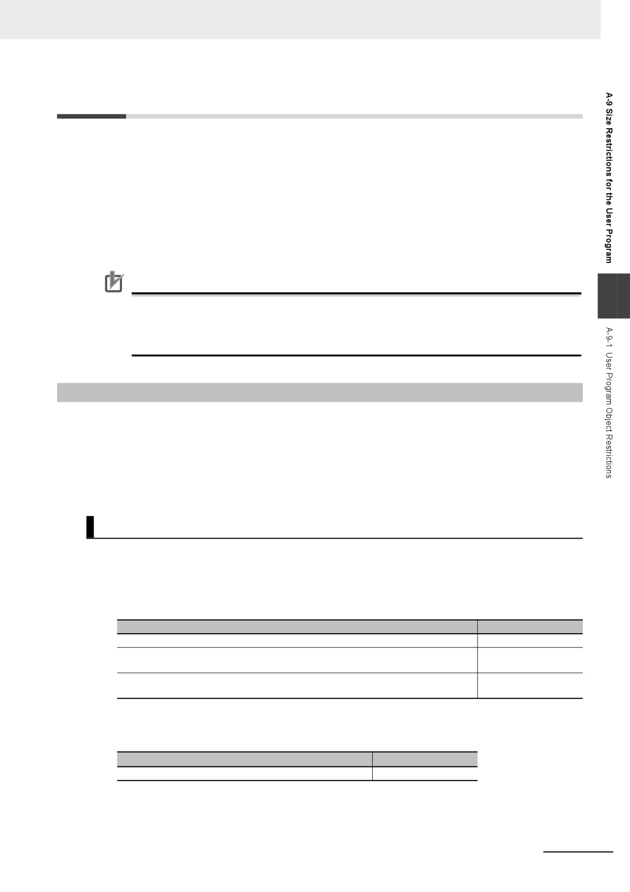
Restriction
NY5
2-
Maximum number of programs
500
Maximum value of the following: Number of function block definitions + Number of
3,000
function definitions + Number of ladder diagram sections
Maximum total number of input, output, and in-out variables in function block and
64
function definitions
z POU Instance Restrictions
POU instances are subject to the following restrictions.
Restriction
NY52-
Maximum number of POU instances
24,000
Refer to Number of POU Instances on page A-117 for information on counting POU instances.
A-115
Appendices
Restrictions to Variables
There are restrictions to both variable usage and variable definitions.
z
Restrictions to Variable Usage
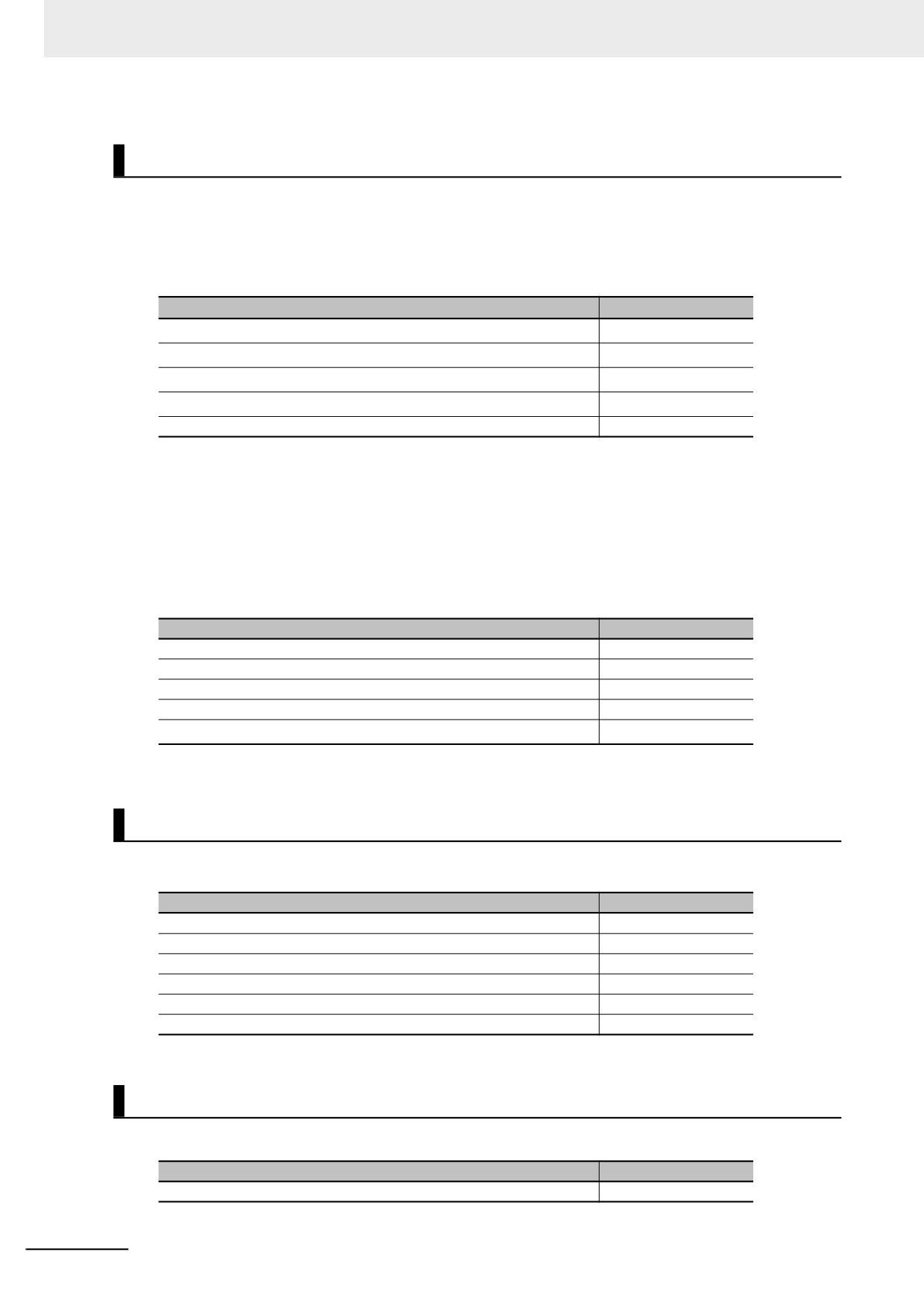
The usage of variables is subject to the following restrictions.
Restriction
NY52-
64
Maximum total size in Mbytes of variables without a Retain attribute*1
4
Maximum total size*1 in Mbytes of variables with a Retain attribute
180,000
Maximum number of variables*2 without a Retain attribute
Maximum number of variables*3 with a Retain attribute
40,000
Maximum number of network variables
40,000
*1
The data size of each variable depends on its data type. Refer to 6-3-5 Data Types for the sizes of the data
types.
*2
Refer to Number of Variables without a Retain Attribute on page A-117 for information on counting vari-
ables.
*3
Refer to Number of Variables with a Retain Attribute on page A-118 for information on counting variables.
z
Restrictions to Variable Definitions
Variable definitions are subject to the following restrictions.
Restriction
NY5 2-
Maximum number of elements per array
65,535
Maximum number of dimensions in an array
3
Maximum size in MB of an array
8
Maximum value of a subscript (element number) for an array
65,535
1,986
Maximum size in bytes*1 of a string variable
*1
The NULL character at the end must be counted. Therefore, there are 1,985 single-byte characters in a
string that has a size of 1,986 bytes.
Restrictions to Data Type Definitions
Data type definitions are subject to the following restrictions.
Restriction
NY5 2-
Maximum number*1 of data type definitions
4,000
Maximum number of levels in a structure definition
8
Maximum number of members in a structure definition
2,048
Maximum size in MB of a structure variable
8
Maximum number of members in a union definition
4
Maximum number of enumerators in an enumeration definition
2,048
*1
Refer to Number of Data Type Definitions on page A-118 for information on counting data types.
Restrictions to Constants (Literals)
The constants (literals) are subject to the following restrictions.
Restriction
NY5 2-
Maximum size in bytes of a constant (literal)
1,985
A-116
Appendices
A-9-2
Counting User Program Objects
This section describes how to count POU instances, variables with a Retain attribute, variables without
a Retain attribute, and data type definitions. The information in this section is provided only as guide-
lines. The methods for counting objects sometimes varies with the unit version of the NY-series Control-
ler. Always use the Sysmac Studio to confirm that user program object sizes are suitable.
Number of POU Instances
POU instances are counted as described below.
z Objects Counted as POU Instances
The following objects are counted as POU instances.
• Programs
A
• Function block instances (both user-created instances and instructions are included)
• Functions (both user-created instances and instructions are included)
z Precautions in Counting POU Instances
Observe the following precautions when you count POU instances.
• If n instances of a function block are used for the same function block definition, count them as n
instances.
• If the same function is used more than once in the same task, count them as one instance regard-
less of the actual number of functions.
• If the same function is used in different tasks, count them as one instance for each task.
Number of Variables without a Retain Attribute
Variables without a Retain attribute are counted as described below.
z Objects Counted as Variables without a Retain Attribute
The following objects are counted as variables without a Retain attribute.
• Global variables without a Retain attribute
• Local variables without a Retain attribute in programs and function block instances (both user-cre-
ated instances and instructions are included)
z Precautions in Counting Variables without a Retain Attribute
Observe the following precautions when you count variables without a Retain attribute.
• Count arrays as one variable each regardless of the number of elements.
• Count function block instances as one variable. Both user-created instances and instructions are
included for function block instances.
• Count arrays of function block instances as one variable each regardless of the number of ele-
ments. However, count one variable for each element of the array for the number of variables
without a Retain attribute that are used in the function block.
A-117
Appendices
Number of Variables with a Retain Attribute
Variables with a Retain attribute are counted as described below.
z Objects Counted as Variables with a Retain Attribute
The following objects are counted as variables with a Retain attribute.
• Global variables with a Retain attribute
• Local variables with a Retain attribute in programs and function block instances (both user-cre-
ated instances and instructions are included)
z Precautions in Counting Variables with a Retain Attribute
Observe the following precautions when you count variables with a Retain attribute.
• Count arrays as one variable each regardless of the number of elements.
• Do not count arrays of function block instances. However, count one variable for each element of
the array for the number of variables with a Retain attribute that are used in the function blocks.
Number of Data Type Definitions
Data type definitions are counted as described below.
z Objects Counted as Data Type Definitions
The following objects are counted as data type definitions.
• User-created structure definitions
• User-created union definitions
• User-created enumeration definitions
A-118
Appendices
A-10 Version Information for NY-series
Controllers
This section describes the relationship between the unit versions of NY-series Controllers and the Sys-
mac Studio versions, and the functions that are supported for each unit version.
A-10-1
Relationship between Unit Versions of Controllers and Sysmac
Studio Versions
This section also describes how the unit versions of NY-series Controllers correspond to Sysmac Studio
versions. Normally use the corresponding versions.
A
Unit Versions and Corresponding Sysmac Studio Versions
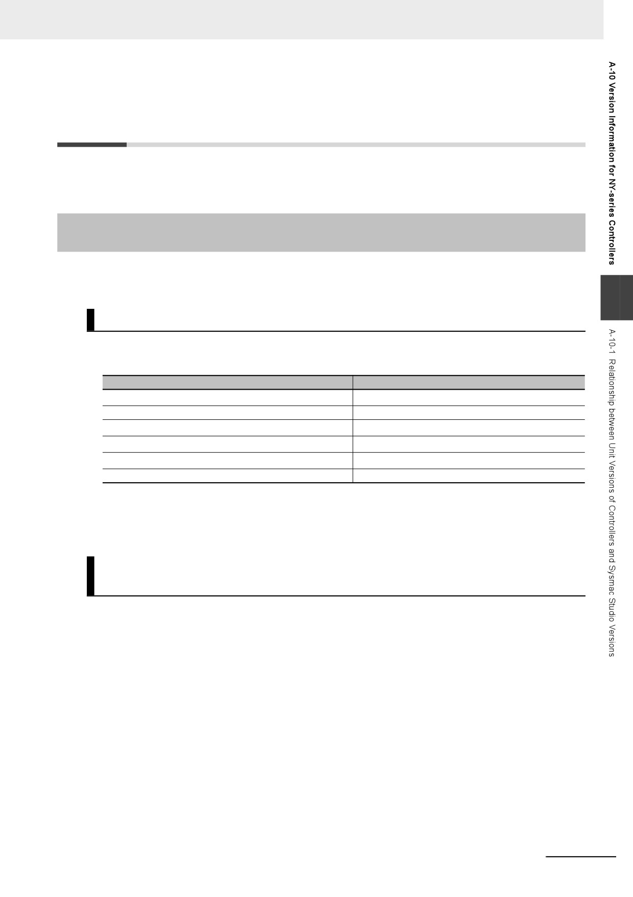
This following table gives the relationship between the unit versions of NY-series Controllers and the
corresponding Sysmac Studio versions.
Unit version of NY-series Controller
Corresponding version of Sysmac Studio
Ver. 1.21*1
Ver. 1.29
Ver. 1.19
Ver. 1.24
Ver. 1.22
Ver. 1.18*2
Ver. 1.16*3
Ver. 1.20
Ver. 1.14*4
Ver. 1.18
Ver. 1.12
Ver. 1.17
*1
There is no NY-series Controller with unit version 1.20.
*2
There is no NY-series Controller with unit version 1.17.
*3
There is no NY-series Controller with unit version 1.15.
*4
There is no NY-series Controller with unit version 1.13.
Specifications When Not Using the Sysmac Studio Version That
Corresponds to the Unit Version of the Controller
The specifications when you do not use the Sysmac Studio version that corresponds to the unit version
of the NY-series Controllers are given in this section.
z Using Sysmac Studio Version 1.16 or Lower
You cannot use the NY-series Controller with Sysmac Studio version 1.16 or lower.
z Using a Lower Version of Sysmac Studio
If you use a lower version of the Sysmac Studio, you can use only the functions of the unit version of
the Controller that corresponds to the Sysmac Studio version.
Example: Unit version of Controller: 1.14
Sysmac Studio version: 1.17
Unit version 1.12 of the Conroller corresponds to Sysmac Studio version 1.17. There-
fore, you can use only the functions that are supported by unit version 1.12 of the Con-
troller. You cannot use functionality that was added for unit version 1.14 or later of the
Controller.
A-119
Appendices
z
Using a Controller with an Earlier Unit Version
If you use an NY-series Controller with an earlier version, select the unit version of the connected
Controller or an earlier unit version in the Select Device Area of the Project Properties Dialog Box on
the Sysmac Studio. You can use only the functions that are supported by the unit version of the con-
nected Controller.
Example: Unit version of Controller: 1.12
Sysmac Studio version: 1.18
Unit version 1.14 of the Controller corresponds to Sysmac Studio version 1.18. How-
ever, the connected Controller is unit version 1.12, so select version 1.12 as the ver-
sion in the Select Device Area of the Project Properties Dialog Box.
If you select version 1.12 as the version in the Select Device Area of the Project Prop-
erties Dialog Box, you can use only the functions that are supported by unit version
1.12 of the Controller. You cannot use functionality that was added for unit version 1.14
or later of the Controller.
Additional Information
Unit Version Settings for Project Devices
• You can select the unit version in the Select Device Area of the relevant dialog boxes on the
Sysmac Studio.
• You can select any unit version that is the same as or earlier than the unit version of the Con-
troller. For example, if the unit version of the Controller is 1.14, select either 1.12 or 1.14.
• The Sysmac Studio will treat the Controller as a Controller with the unit version that is selected
for the project device. For example, if you set unit version 1.12 for project device, you can use
only the functionality for unit version 1.12 on the Sysmac Studio.
• You can transfer a project to the Sysmac Studio if the unit version that is set for the project
device is the same as or earlier than the unit version of the destination Controller.
• Refer to the Sysmac Studio Version 1 Operation Manual (Cat. No. W504-E1-03 or later) for
details on the Select Device Area of the relevant dialog boxes.
A-10-2
Functions That Were Added or Changed for Each Unit Version
This section describes the functions that were added or changed for each unit version of NY-series
Controller.
z Additions and Changes to Functional Specifications
The following table gives the unit version of the Controller and the Sysmac Studio version for each
addition or change to the functional specifications.
Sysmac
Addition/
Unit ver-
Function
Studio
Reference
change
sion
version
Motion control
Single axes
Auxiliary func-
Cam monitor
Addition
1.21
1.29
NY-series Industrial
tion for single-
Panel PC / Indus-
axis control
trial Box PC Motion
Control User's Man-
ual (Cat. No. W559)
Note Refer to the manuals for the function modules for additions and changes to function module functions for
each unit version of the Controllers.
A-120
Appendices
z Additions and Changes to Basic Instructions and Motion Control Instructions
The basic instructions and motion control instructions that you can use have increased or changed
for the new unit version of the Controller. For details, refer to the NY-series Instructions Reference
Manual (Cat. No. W560) and NY-series Motion Control Instructions Reference Manual (Cat. No.
W561).
z Additions and Changes to Controller Events
The events that can occur have increased or changed for the new unit version of the Controller.
There are also changes in the recovery methods to use when some errors occur.
For details, refer to the NY-series Troubleshooting Manual (Cat. No. W564).
z Additions and Changes to System-defined Variables
The system-defined variables that you can use have increased or changed for the new unit version
of the Controller. Refer to A-3 System-defined Variables for details.
A
A-121