Handbook of Watch and Clock Repairs (1972) - page 3
68
WATCH AND CLOCK REPAIRS
Pressing the check-spring downward causes the castle wheel
to move down the winding stem, become disengaged from the
crown wheel, and mesh with the intermediate wheel which is in
mesh with the motion work.
In this position turning the winding stem will operate the
motion work and alter the hand setting.
A downward pressure on the winding button will overcome the
resistance offered by the check-spring and the pull-out piece and
the keyless work will be restored to its original position.
If the winding mechanism is stiff to operate, inspect the ratchet
wheel for freedom of movement. If the wheel is binding on the
plate either the shoulder of the barrel arbor is not projecting
clear of the plate or the arbor holes in the plate are worn.
In the first case, when screwing the ratchet wheel to the arbor
the wheel will be pulled down on to the plate. Inspect the plate
and the mainspring barrel for burrs around the arbor hole and
if necessary skim the surfaces in the turns. The alternative is to
fit a new arbor. If the arbor holes have become enlarged the arbor
will lean over causing the ratchet wheel to rub against the plate.
The remedy is to bush the arbor holes in the plate.
Slipping is caused by badly fitting wheels and badly meshed
wheel teeth. Turn the winding stem in the direction of winding
and observe the effect on the wheels. If the crown wheel slips on
the castle wheel, the cause will be worn teeth or worn winding
stem holes in the wheels or a worn winding stem. The wheels
should not be loose on the stem. Renewal of parts will effect a
cure.
If the up-and-down shake of the transmission wheel is excessive
the action of rotating the crown wheel will cause the transmission
wheel to be pushed away, until the shake is taken up, resulting in
insufficient depth of mesh and subsequent slip. The transmission
wheel shake must be reduced. First ensure that the transmission
wheel boss is screwed down tightly. If this is in order, then the
height of the wheel bearing must be reduced. Some transmission
wheels are made complete with a wheel bearing in the form of a
boss. The length of this boss can be reduced by stoning. If the
KEYLESS WORK
69
bearing forms part of the plate, then the height of the bearing
must be machined down in the turns.
Sometimes when pulling out the winding stem to alter the
setting of the hands, the stem comes away from the movement.
This is caused by the pin of the pull-out piece failing to retain the
stem in position. If the pin of the pull-out piece, or the groove in
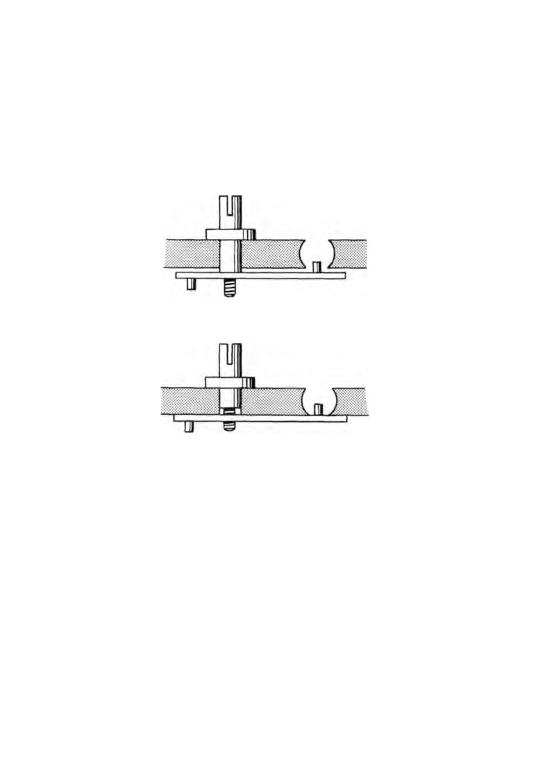
Fig. 30. Pull-out piece.
the winding stem are worn, replacement parts will be required.
If the winding stem becomes loose in the plate caused by the
plate being worn, the excessive side-shake of the stem will result
in partial disengagement of the pin of the pull-out piece in the
winding stem groove. In such cases the plate must be bushed or
an oversized winding stem fitted.
Another cause of the winding stem coming away is the pull-out
piece becoming loose on the pull-out piece screw. When correctly
fitted the screw should be tight in the pull-out piece but free to
move in the plate so that when the winding stem is pulled out or
pushed in, the pull-out piece and its screw rotate as one.
70
WATCH AND CLOCK REPAIRS
When the pull-out piece screw is in position make sure that the
shoulder nearest the thread projects beyond the face of the plate
(Fig.
30, a). If it does not, it means that when the pull-out piece
screw is threaded into the pull-out piece, the pull-out piece will
be held against the plate before the screw is fully tight (Fig.
30 b)
CHAPTER NINE
Barrels, mainsprings and fusee
chains
BECAUSE the mainspring and barrel assembly operates very
slowly, it must be free-moving and smooth-acting. There must
be no possibility of rubbing or tendency to stick.
If rubbing has taken place, an inspection of the barrel and the
watch frame quite often reveals the tell-tale marks.
Let us first make sure that the barrel rotates freely and squarely
about the arbor.
Barrels. Place the arbor in the barrel and snap the cover on.
The arbor should have slight end-shake.
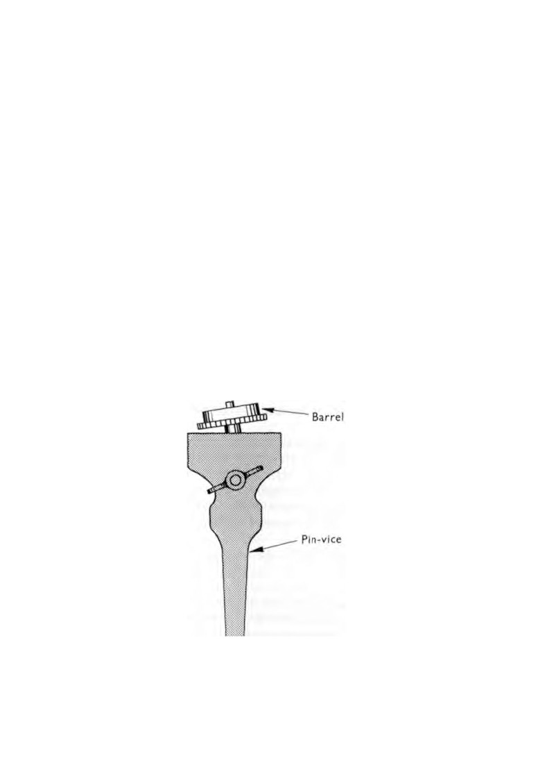
Now hold the end of the arbor in the jaws of a pin-vice with
the cover uppermost
(Fig.
31). The arbor should be held at an
angle so that the gear teeth on one side are just clear of the jaws
Fig. 31. Checking barrel for running true.
71
72
WATCH AND CLOCK REPAIRS
of the pin-vice. By rotating the barrel it will be seen whether the
barrel is running true.
If the barrel wobbles, then the arbor hole in the barrel or the
cover needs bushing. Enlarging the hole to take the bush is best
done on a lathe, and fitting the bush is carried out with the aid of
a watchmaker's punch and stake. If you do not possess this
equipment then the work will have to be sent away.
With the barrel free and square about the arbor, fit the barrel
between the plates. There should be no end movement of the
arbor between the plates. All that is required is freedom of the
arbor to turn when the spring is being wound.
A loose barrel cover can be tightened by placing it on a flat
steel stake and gently tapping all round the edge with the flat of a
hammer. The hammer face must meet squarely with the cover if
marks and bruises are to be avoided. Use a stroking action by
bringing the hammer downward and outward. After each tap,
rotate the cover a little until the place of starting has been
reached. This will spread the metal until a good fit is obtained.
To fit a new mainspring hook to a barrel, first drill a hole in
the side of the barrel at a slight angle pointing away from the
direction of pull of the mainspring. The hole is then threaded
slightly undersize.
Taper a piece of steel wire by filing and cut a thread with a
screw plate, holding the wire in a pin-vice. Remove the pin-vice,
cut the wire close to the screw plate and shape the protruding
piece of wire into a hook by filing.
Unscrew the threaded wire from the screw plate and insert the
small diameter end of the wire into the hole in the barrel entering
from the inside.
The protruding wire on the outside is now held by the pin-vice
and the wire is screwed into position by unscrewing from the
outside.
The hook should project into the barrel a distance no greater
than the thickness of a piece of the mainspring.
When in place remove the pin-vice, cut off the wire on the out
side, file down close to the barrel and finish with an oilstone slip.
BARRELS, MAINSPRINGS AND FUSEE CHAINS
7 3
Similarly, new hooks can be fitted to barrel arbors. A hole is
drilled in the arbor and a steel pin is driven in tight. The new
pin is shaped by filing and finished with an oilstone slip.
Occasionally a barrel tooth becomes bent as the result of a
mainspring breaking. The bent tooth can often be straightened
by inserting the blade of a knife at the side of the bent tooth and
gently levering back into position.
Mainsprings. If a mainspring breaks close to the outer end, it
can be repaired. A break anywhere else necessitates the fitting of
a new spring.
When a replacement mainspring is needed, it is better to
purchase a spring from the manufacturer of the watch. The
length of the spring will be correct and it will be hooked and
ready for fitting into the barrel.
The alternative is to purchase a suitable spring, cut it to
length and shape the outer end. Assuming the spring to be
replaced is the correct gauge, width and length, then the purchase
of a replacement should present no problems.
However, it is as well to know a little about the design of a
mainspring and a barrel assembly in case the spring to be replaced
does not conform to the specification laid down by the watch
manufacturer.
Two identical springs, but of different lengths will, if bent to
the same curve, apply different forces. If one spring is half the
length of the other it will apply twice the force.
A long spring will take up more space in the barrel and it
therefore cannot be wound as many turns as a shorter spring.
This will result in the watch unwinding itself too quickly.
A spring that is too short will when wound exert too great a
force and cause a high rate of wear in the wheel train and
escapement.
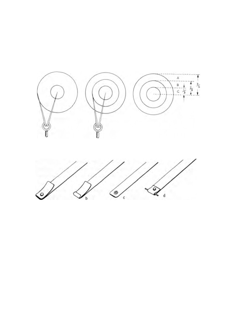
A simple way to establish how long the spring should be is
illustrated in figure
32. Place the barrel on a sheet of metal and
with a sharp pointed tool scribe a circle using the barrel hole as
a guide. Mark the centre of the circle. Take a pair of dividers,
place the point of one leg on the centre of the circle and adjust
74
WATCH AND CLOCK REPAIRS
the dividers until the other leg just touches the base of the barrel
wall (Fig.
32, left). Measure this distance and readjust the dividers
to two-thirds of the original distance. With the barrel still in
position on the sheet of metal lightly scribe a circle on the barrel
inner face
(Fig.
32, centre).
Fig.
32. Marking barrel to show correct mainspring length. A. Space
for unwound spring. B. Space for wound spring. C. 1/2 diameter or arbor.
Fig. 33. Methods of hooking outer ends of mainsprings.
When the new spring is in the barrel, it should take up the space
between the barrel wall and the scribed line.
The force of a spring also varies with the thickness and the
height. If it is twice the thickness the force is increased eight times.
A spring which is twice the height will have twice the force.
If the spring is too thick it will not be possible to obtain the
required number of turns. If the height is too great the spring
will foul the barrel and the cover, and if the height is insufficient
then the spring will buckle and once again foul the barrel and
the cover.
BARRELS, MAINSPRINGS AND FUSEE CHAINS
7 5
If the inner face of the barrel cover is recessed, the height of the
mainspring should be level with the shoulder in the barrel wall
upon which the cover rests. If the cover is not recessed then the
height of the spring should be just below the shoulder.
There are various methods of hooking the outer ends of main
springs to barrels and figure
33 illustrates those in common use.
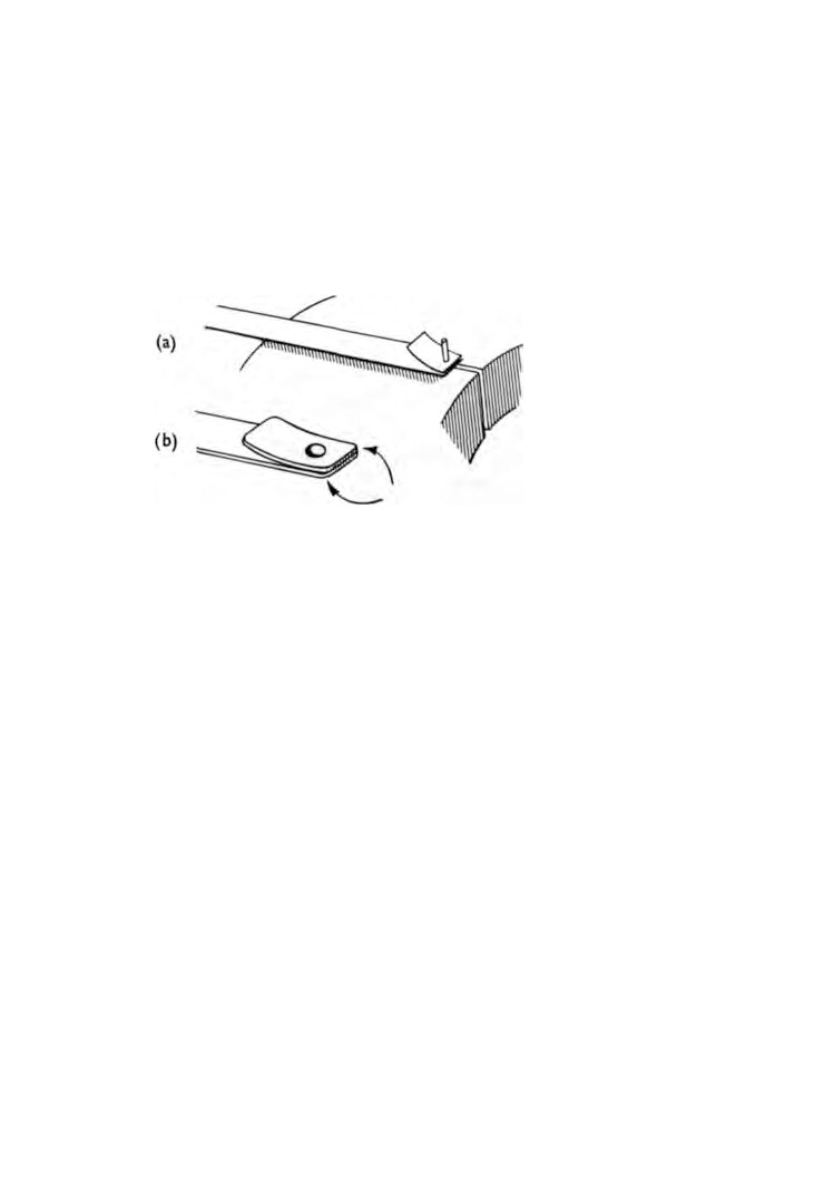
Fig. 34. Fitting a riveted hook.
To fit a riveted hook, soften the extreme end of the spring in a
spirit flame by heating to a black heat. Hammer the end of the
spring flat and drill a small hole to take a rivet. Select a short
piece of spring the same width and thickness as the mainspring
and drill a hole in one end using the same drill as before. File the
other end square with the sides. Hold the two pieces of spring
together and broach out both holes as one. Remove the burrs
and polish both pieces with fine grade emery paper working the
grain down the length of the spring.
Cut off a short length of steel wire, hold it in the pin-vice and
file it to fit the hole. Push the wire into the hole and grip the wire
in a vice
(Fig.
34, a).
Cut the wire close to the face of the spring and rivet over with
a round-face hammer.
Remove the pin from the vice and cut off the other end as
before. Place the riveted head in a riveting stake or dolly and
complete the operation by riveting the other end. File the end as
shown in figure
34, b, and remove the burrs. Polish with a fine
grade emery paper.
76
WATCH AND CLOCK REPAIRS
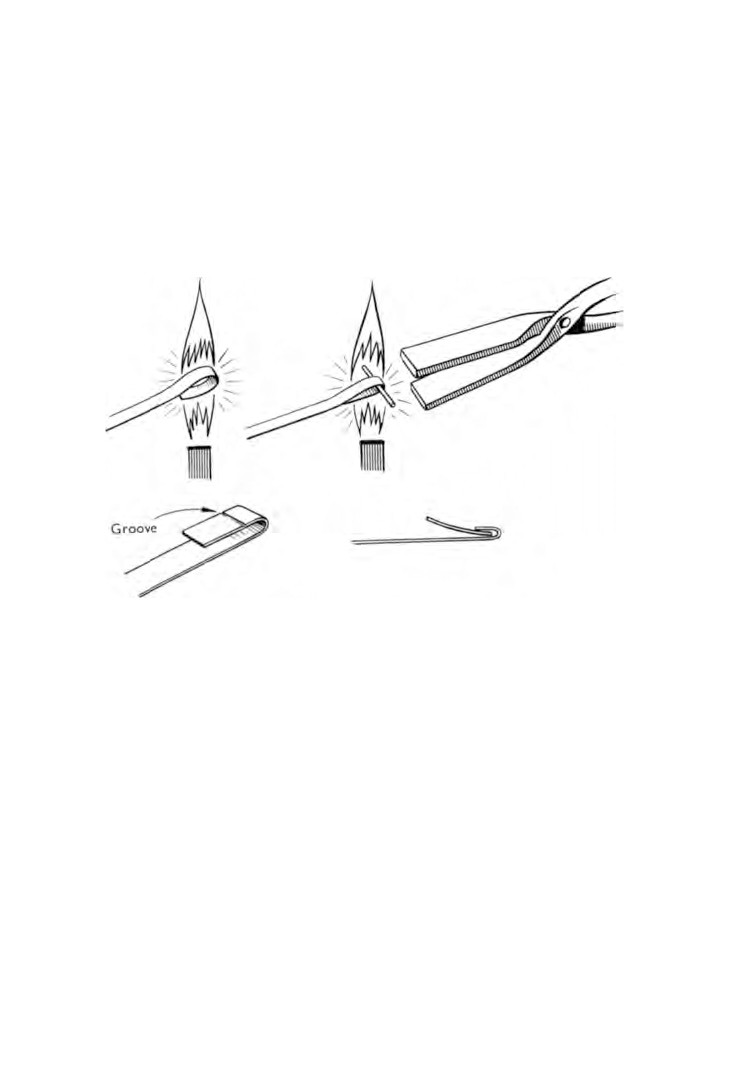
A very narrow spring such as would be found in a flat watch
would be weakened by drilling a hole. An alternative method of
hooking such a spring is shown in figure 35.
Break off the end of the spring to within two or three inches
of the required length. Heat the spring, at about the point where
the end is to be, in a spirit flame and bend upward and over using
Fig. 35. Making a loose-piece.
flat-nose pliers. The pliers should be pre-heated to prevent the
heat of the spring being absorbed by the cool pliers. Keep the
spring in the flame whilst bending is taking place and do not force
the spring. Once the correct temperature has been reached,
bending will be found easy. Take the piece of broken spring and
place a short length in the loop of the mainspring. Reheat and
slowly close the mainspring loop over the short length of spring
and gently but firmly squeeze in to shape. Withdraw the short
length of spring.
Cut a groove across the face of the short arm of the loop with
a file, bend back and snap off. File the end square and remove
the burrs.
BARRELS, MAINSPRINGS AND FUSEE CHAINS
7 7
From the short length of spring cut a piece long enough to form
the hook, file the ends square and remove the burrs.
Polish both springs with fine grade emery paper and push the
short length of spring into the hooked end of the mainspring.
To make an eye, soften the extreme end of the spring by heating
in the spirit flame. Drill a hole in the end and then enlarge it with
a broach to fit loosely over the barrel hook. The last few cuts of
the broach should be made at an angle to correspond with the
angle of the barrel hook. The burrs produced by the broach must
now be removed.
The end of the spring has to be curved to the same radius as
that of the barrel. This will ensure that the spring is correctly
hooked.
Place the spring, outer face downward, on a block of lead, and
tap the inner face with a watchmaker's hammer. This will
decrease the radius of the curve.
Finish off by polishing the end of the spring with fine grade
emery paper.
The brace method of hooking a mainspring is used in almost all
American watches. The brace consists of a short length of spring,
the same width as the mainspring but slightly thicker. It carries
two pivots that project into a hole in the barrel base and another
hole in the barrel cover.
The brace is secured to the end of the mainspring by a rivet. It is
better to purchase a new brace rather than make one. Replace
ment braces are supplied drilled and complete with a rivet. When
the spring is fully wound, the brace swinging on its pivots, moves
across the barrel.
Make sure that the pivots do not project beyond the barrel or
the barrel cover. The width of the brace should not be greater
than the width of the mainspring because fouling may occur
between the edges of the brace and the faces of the barrel and the
barrel cover during unwinding of the spring.
Fusee chains. Hold the broken end of the chain and insert a
thin blade beneath the link plate. Gently lever the plate away
from the rivet until the outline of the rivet can be seen.
78
WATCH AND CLOCK REPAIRS
Place the chain on a graduated stake and with a blunted sewing
needle held in a pin-vice push the rivet out. It may be necessary
to tap the pin-vice with a hammer.
Treat the other broken end in the same way.
Select a sewing needle from which to make the new rivet and
heat it to a blue. File the needle almost to size with a very fine
file and finish off with an oilstone slip.
Fit the ends of the chain into each other, making sure that
the two end hooks are on the same side, and insert the needle
into the rivet holes. Replace the chain over the stake and gently
tap the needle home.
Cut both ends of the needle off close to the side plates and file
flush. Lay the chain on its side on a metal stake and gently rivet
each end of the needle with a round-face hammer.
In carrying out this repair, frequent checks are necessary to
ensure that the centre plate on one end of the chain is free to
swing between the side plates of the other end of the chain.
CHAPTER TEN
Escapements
THE two most popular forms of escapement today are the lever
and the pin-pallet.
Whereas the lever has great precision and can be relied upon
to function accurately over long periods, the pin-pallet is a cheap
and robust product that lends itself well to mass production.
Even so, the good service obtained from a pin-pallet escarpment
cannot be ignored.
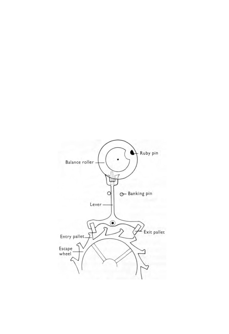
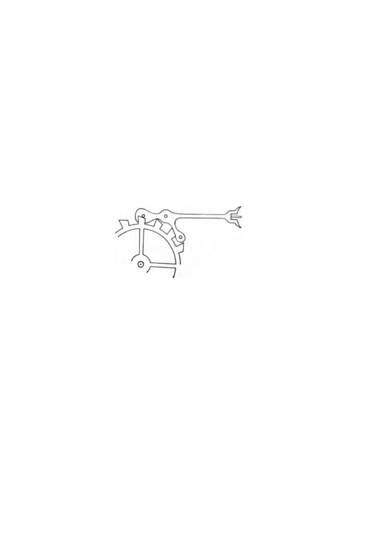
The lever (Fig.
36). To enable faults in a lever escapement to be
identified a working knowledge of its function is necessary.
Fig. 36. Lever escapement.
79
80
WATCH AND CLOCK REPAIRS
We have seen how power from the mainspring, passing through
the train of wheels reaches the escape wheel. We have learned
that it is the pallets of the lever, interrupting the teeth of the
escape wheel, that prevent the wheel train from rotating at a high
speed during the unwinding of the mainspring.
The escapement consists of the escape wheel, the lever, two
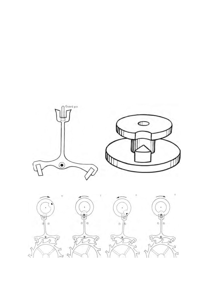
banking pins and the balance. Figure
37 illustrates the lever in
detail and figure 38 shows the roller which is fitted to the balance
staff.
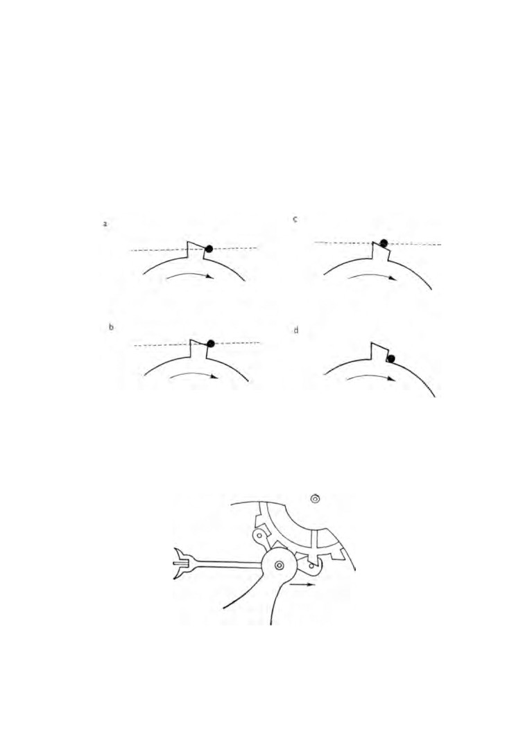
In figure 39 we can see the stages through which the escapement
passes in order to release the escape wheel one tooth at a time.
Fig. 37. The lever.
Fig. 38. The roller.
Fig.
39. The lever escapement—sequence of movements.
ESCAPEMENTS
81
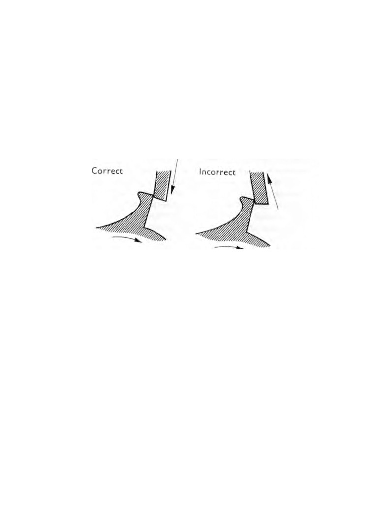
The escape wheel tooth hits the locking face of the entry pallet
stone and the escape wheel is brought to rest
(Fig.
39, a). The
power in the escape wheel causes the tooth to press against the
locking face of the entry pallet stone pulling the stone down. This
downward movement is called the draw (Fig. 40). The draw pulls
the lever hard against the banking pin and holds it there. This last
movement of the lever is known as the run to banking. If the
watch received a shock sufficient to overcome the draw, the lever
Fig. 40. The draw.
would no longer be held against the banking pin and would be
free to pass across to the other banking pin. This would cause the
watch to stop. To prevent this happening, a guard pin is fitted at
the end of the lever which, under conditions described above,
would come in contact with the roller and further movement of
the lever would be checked.
To allow the lever to pass under normal conditions, a groove is
cut in the edge of the roller level with the ruby pin.
The balance completes its swing, stops and reverses under the
tension of the balance spring. The ruby pin enters the notch of
the lever and moves the lever away from the banking pin. This
causes the entry pallet stone to be pulled away from the escape
wheel thereby releasing the tooth
(Fig.
39, b).
The ruby pin continues to move round pushing the lever
farther over and the exit pallet stone moves in towards the escape
82
WATCH AND CLOCK REPAIRS
wheel. The adjacent tooth strikes the exit pallet stone on its
locking face and the lever is held firmly against the other banking
pin (Fig.
39, c).
The balance completes its swing and reverses direction. As the
ruby pin re-enters the notch in the lever, the lever is moved away
from the banking pin, pulling the exit pallet stone away from the
escape wheel tooth. The escape wheel tooth, being freed from the
locking face, now presses against the impulse face of the exit
pallet stone. It is this impulse, transmitted through the lever, that
gives a further swing to the balance
(Fig.
39, d). While the exit
pallet stone is being pushed away, the entry pallet stone is moving
in to stop the next tooth and the cycle of operations repeats itself.
For such small surfaces to perform these operations efficiently
over long periods calls for a high standard of workmanship.
Slight damage or wear can destroy the timing of the escapement
or cause the movement to stop altogether. Let us then examine the
escapement to detect any faults that may be present. Check the
balance staff end-shake by holding the balance arm in a pair of
tweezers and moving the balance wheel up and down. To know
when the end-shake is excessive calls for experience, but if you
remember that providing the end-shake is just sufficient to retain
a film of oil, then any excess is undesirable.
Another test for end-shake is to wind the mainspring a few
turns and set the movement in motion. Apply light pressure to
the balance staff end-stone with a piece of pegwood and if this
stops the balance, the end-shake is insufficient. Hold the watch
movement between the thumb and forefinger of one hand and
place the tip of the forefinger of the other hand lightly on the
rim of the balance wheel. Very little movement of the finger is
required to rock the balance.
Examine with the aid of an eye-glass the side-shake of the top
and bottom pivots.
It is almost certain that wear will be the cause of excessive shake
and the remedy is to fit a new staff and to renew the pivot
bearings.
Now remove the balance cock and lift out the balance. In this
ESCAPEMENTS
83
condition the pallet staff can be checked for shake, the same
remarks applying here as for the balance.
We now turn our attention to the locking of the escape wheel
teeth by the pallet stones. First, let the mainspring down. Now
fold a small piece of tissue paper and place it under the guard pin
of the lever ; this will hold the lever in any position we like to put it.
Take a pointed pegwood stick and position the escape wheel
and lever so as to bring a tooth in contact with the impulse face
of the entry pallet. Very slowly move the escape wheel forward
until the tooth is just clear of the pallet. In this position the exit
pallet should be locking a tooth against its locking face.
Now raise the exit pallet stone slightly and move the escape
wheel forward so that the tooth comes on to the impulse face.
Make sure that in this position the entry pallet stone moves in
to lock the next tooth. This test must be repeated for all fifteen
teeth. If the entry stone mislocks on any tooth the cause must be
investigated.
Examine the tips of the escape wheel teeth. If they are showing
obvious signs of wear, the escape wheel must be renewed.
Examine the escape wheel pivot bearings and the pallet pivot
bearings for wear. Any of these faults will cause the escape wheel
and the pallets to function at too great a distance from each other.
If no fault is found here, then adjustment must be made by
altering the positions of the pallet stones.
The stones are held in the pallets by shellac. If the shellac is
warmed, the stones can be moved and held in their new positions
until the shellac has set. If the entry stone is pulled out, the exit
stone must be moved in by the same amount, otherwise the exit
stone will be too deep when locking.
Remove the lever from the watch and examine the impulse
faces of the pallet stones. If they are pitted they must be replaced
by new stones.
Place the lever on a blueing pan together with a small chip of
shellac. Heat the pan in a spirit flame until the chip of shellac
is softened. This will be the correct temperature at which to
move the stones.
84
WATCH AND CLOCK REPAIRS
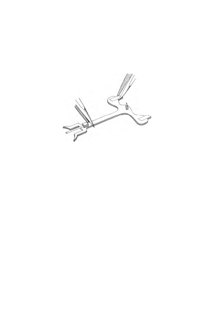
Leave the lever on the pan and, holding the lever in a pair of
tweezers, adjust the stone with a second pair of tweezers (Fig. 41).
In many watches the undersurface of the pallets carries a film
of shellac. If this film is disturbed when adjustments are made, be
sure to make it good before replacing the lever in the movement.
Fig. 41. Adjusting pallet stone.
If new pallet stones have to be fitted, the lever must be sent to
the supplier with the order.
Place the lever on the blueing pan and hold it over the spirit
flame. Insert the new stones the right way up. Put a small chip of
shellac on the back of each stone and let it run over the face.
Move the stone in and out of the pallet allowing the shellac to
run in the join. If most of the shellac runs into the join, add
another small piece to run over the face to restore the film. Fit
the lever into the movement and test the locking. When the
locking is correct, lift out the lever and remove any surplus
shellac but leave the film intact.
The next test is to see whether the lever has the correct run to
banking. It is this free movement of the lever that makes draw
possible.
A few turns are given to wind the mainspring. The lever is
wedged with tissue paper as before and very slowly moved to one
side until a tooth of the escape wheel just touches the locking face
ESCAPEMENTS
85
of one of the pallet stones. At this point the distance between the
lever and the banking pin should be about the thickness of a thin
razor blade. Both sides of the lever should have the same distance.
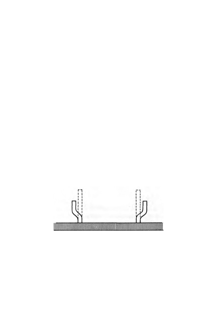
If the run to bank is too great, the distance between the banking
must be reduced. If banking pins are employed, the pins are bent
towards each other and then given a second bend to bring them
parallel
(Fig.
42). This is important, otherwise if the pins were
left tapering towards each other the run to banking would be
further reduced when the movement was turned over.
Some American watches use pins placed eccentrically in screws.
All that is needed here is that the screws are turned until the pins
are in the correct position in relation to the lever. The problem of
maintaining the pins in a vertical attitude does not arise.
Solid bankings are employed in some movements and with
these a little extra work is required to make adjustments.
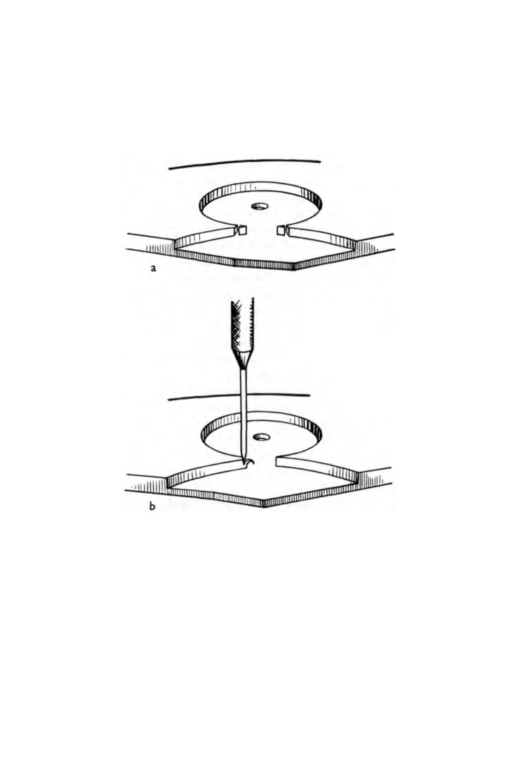
To decrease the gap a slot must be cut in each banking with a
very thin file such as one used for deepening the screwdriver slots
in screw heads (Fig. 43, a). The two pillars thus formed are bent
inward and their inner faces filed vertically.
Increasing the gap of solid bankings necessitates the removal
of a thin shaving of metal from the inner face using the blade of
a sharp screwdriver (Fig. 43, b).
Fig. 42. Adjusting banking pins.
Now let us look at the draw to see that we have the right
amount. Remove the tissue paper wedge from the lever, and slowly
move the lever to one side until the locking face of one of the
pallets is just clear of the escape wheel tooth.
86
WATCH AND CLOCK REPAIRS
At this point release the lever which should jump across to the
banking. Both pallets must be tested in the same way.
If the lever is sluggish when moving indicating insufficient
draw, the attitudes of the stones in the pallets must be altered.
Fig. 43. Solid bankings.
Let the mainspring down and lift the lever from the movement.
Place the lever on the blueing pan with the shellac side uppermost
together with a chipping of shellac. Hold the pan in a spirit
flame and heat until the piece of shellac becomes soft. Place the
pan on the bench and hold the lever with tweezers. Push the
pallet stone to one side in the direction required and hold it there
until cooled.
ESCAPEMENTS
87
Replace the lever in the movement, wind the mainspring a few
turns and test again. If the draw is still insufficient another pallet
stone, slightly narrower must be fitted.
Sometimes a lever movement stops each time it is shaken or
receives a slight shock. If examination reveals the lever at rest
on the wrong side of the roller, the fault is a short guard pin.
Shaking the movement causes the lever to pass the roller in the
wrong direction and when the balance reverses its swing the ruby
pin comes to rest on the edge of the lever horn instead of entering
the notch.
The remedy is to lengthen the pin and this can be done either
by bending it forward or by fitting a new one.
Fig. 44. Pin pallet
The original pin is pushed out in the direction of the pallets. A
new brass pin with a long taper is made by the pin-filing method.
Smooth the pin with the finest grade emery stick and finish with
the flat burnisher.
Insert the new pin from the pallet end of the lever. Cut off the
surplus length at the back with the nippers, and file the operating
end of the pin to the required length. Finish off the end with an
Arkansas stone.
Pin pallet (Fig.
44). In this form of escapement the pallets are
fitted with pins instead of stones, and the impulse faces are cut
on the ends of the escape wheel teeth. The draw of the escape
wheel teeth on the pallet pins causes the pins to bank against the
bottom of the teeth, it is therefore quite usual for some manu
facturers not to fit banking pins with this type of escapement.
88
WATCH AND CLOCK REPAIRS
Mislocking is a common cause of failure in this type of escape
ment but it is quite easy to test and the remedy is simple.
Give a few turns to the mainspring. With a pointed pegwood
stick rotate the balance very slowly until an escape wheel tooth is
released. In this position make sure that the other pallet pin has
locked another tooth. For the locking to be correct the locking
face of the tooth must be above the centre of the pallet pin
(Fig.
45, a). Incorrect locking is illustrated in figure 45, b and c.
Fig. 45. Pin pallet locking, (a) Correct. The escape wheel tooth strikes
the pallet pin above the centre, (b) Incorrect. The escape wheel tooth
strikes the pallet pin below the centre,
(c) Mislock. The pallet pin is
struck by the impulse face of the escape wheel tooth,
(d) Draw. The
pallet pin is pulled down to the base of the tooth.
Fig. 46. Direction of bending the tongue to overcome mislocking.
ESCAPEMENTS
89
Now carefully rotate the balance a little farther in the same
direction and watch the draw. The tooth should pull the pallet
pin down to the base of the tooth (Fig. 45, d).
Repeat this test on both pallet pins and for all fifteen teeth of
the escape wheel.
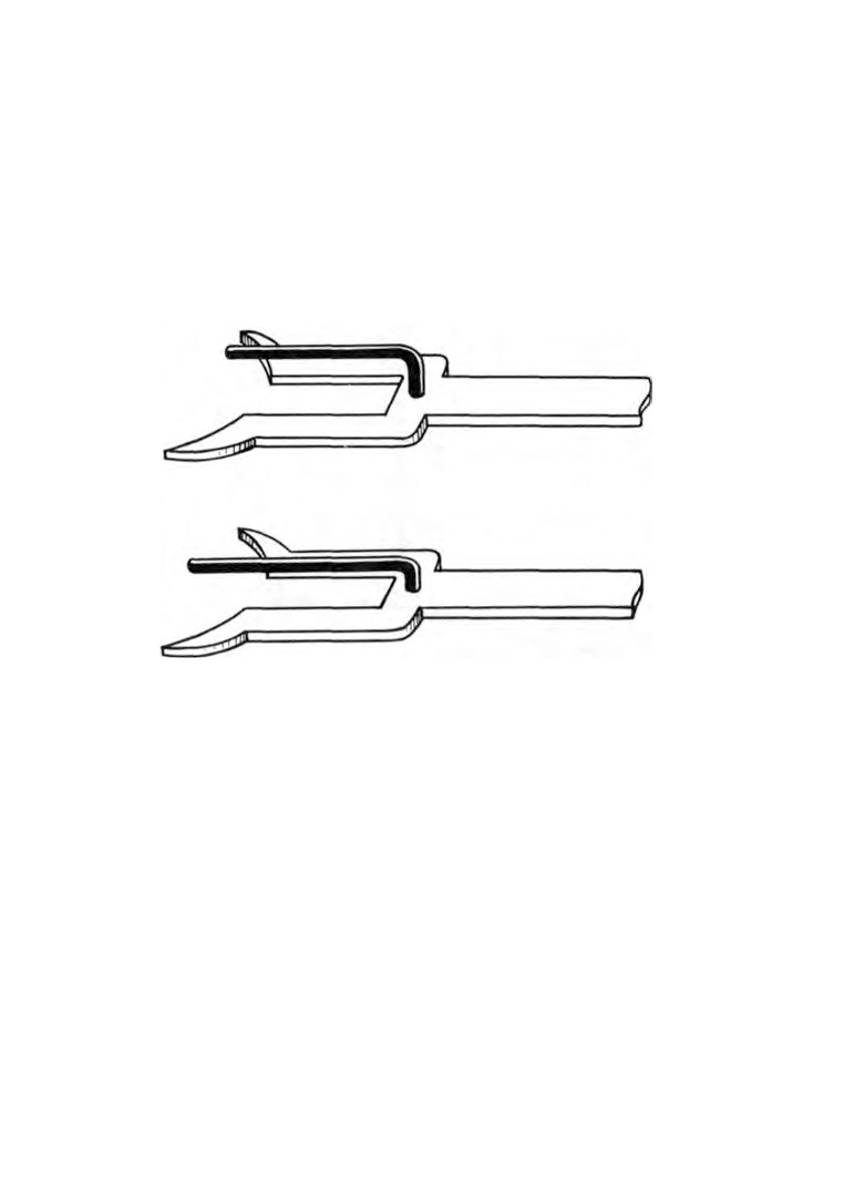
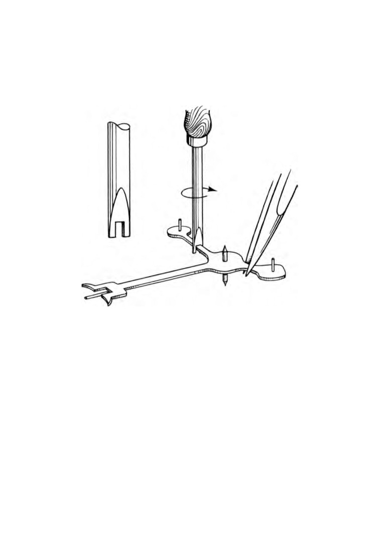
If mislocking occurs anywhere the pallets must be brought
closer to the escape wheel. This is done by slightly bending the
Fig. 47. Lengthening the guard pin.
tongue that carries the pallet pivot bearing hole. The tongue is
held by the long nose pliers and bent sideways towards the
escape wheel (Fig. 46).
After bending repeat the above tests.
To test the draw of the escape wheel teeth rotate the balance
until the impulse pin is clear of the lever. Hold the balance in this
position and move the lever against the roller. If the escapement
has sufficient draw, the lever will jump back into its original
position when released. This test must be carried out on both
pallet pins and with all fifteen teeth of the escape wheel. If the
draw is weak the remedy is a replacement wheel.
The amount of shake on the roller needs to be checked. By
moving the balance round so that the impulse pin on the roller
90
WATCH AND CLOCK REPAIRS
is clear of the notch in the lever, the shake can be tried. Now
swing the balance in the opposite direction and try the shake
again. Both should be equal.
If it is found that there is more shake on one side, the lever must
Fig. 48. Closing the pallet arms.
be removed and bent sideways in the direction of reducing the
greater shake. The lever is placed on its side on a stake held in
the vice. A chisel with the cutting edge rounded off is placed on
the upper side of the lever and a light tap given with a hammer.
This will cause the lever to bend upward.
Sometimes it is found that both sides have no shake at all, in
this case the length of the guard pin must be reduced.
If the shake is excessive on both sides the guard pin must be
increased in length. This can usually be done by first straightening
the pin and then re-bending it as close to the lever as possible
(Fig.
47). In some watches the guard pin is cut from the solid in
which case the metal has to be stretched by light tapping with a
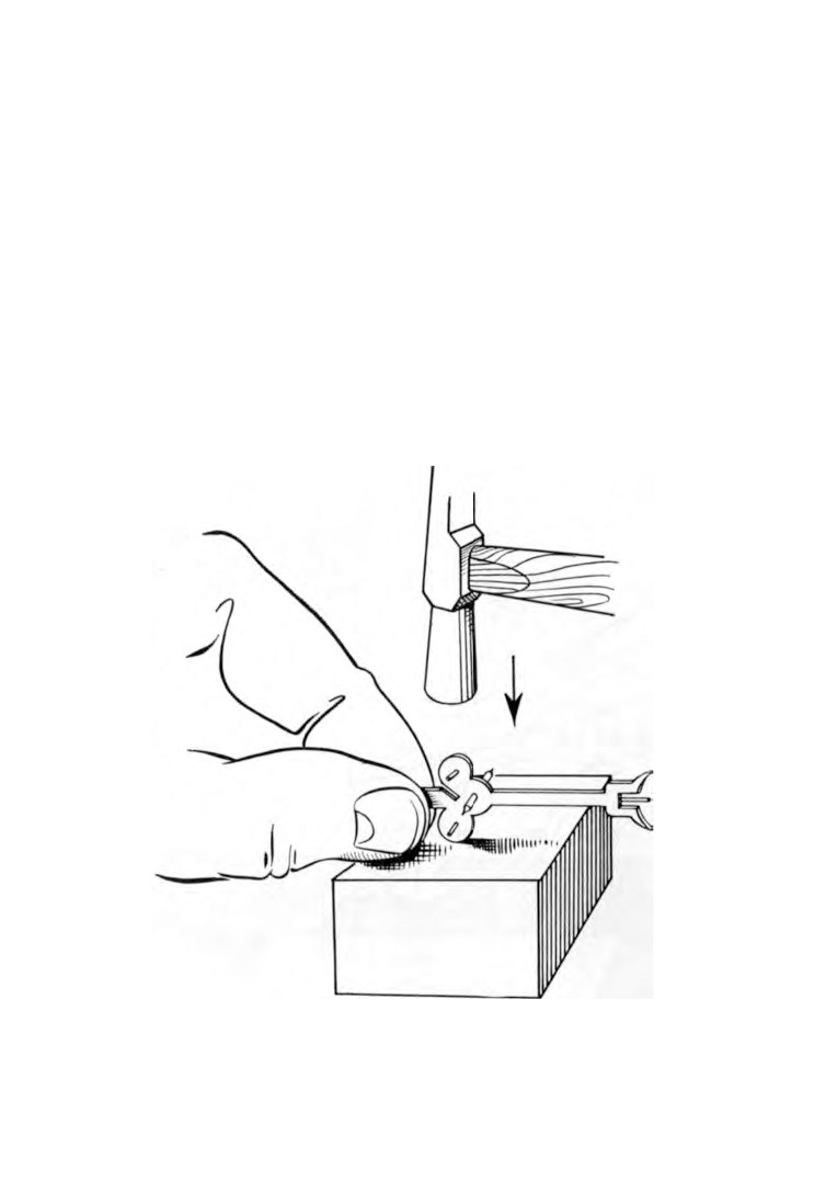
ESCAPEMENTS
91
hammer, with the guard pin resting on a metal strip held in the
vice.
After any adjustment replace the lever, re-check the shake, and
make sure the guard pin engages on the roller and that the impulse
pin engages freely in the lever notch.
The distance an escape wheel tooth moves before being stopped
by a pallet pin is known as the drop. This distance must be the
same on both pins.
Move the balance round slowly as before and note the amount
of drop on the pin. Reverse the direction of the balance and note
the amount of drop on the other pin.
If one side is greater than the other, then the pallet arm on the
greater side must be bent toward the other arm.
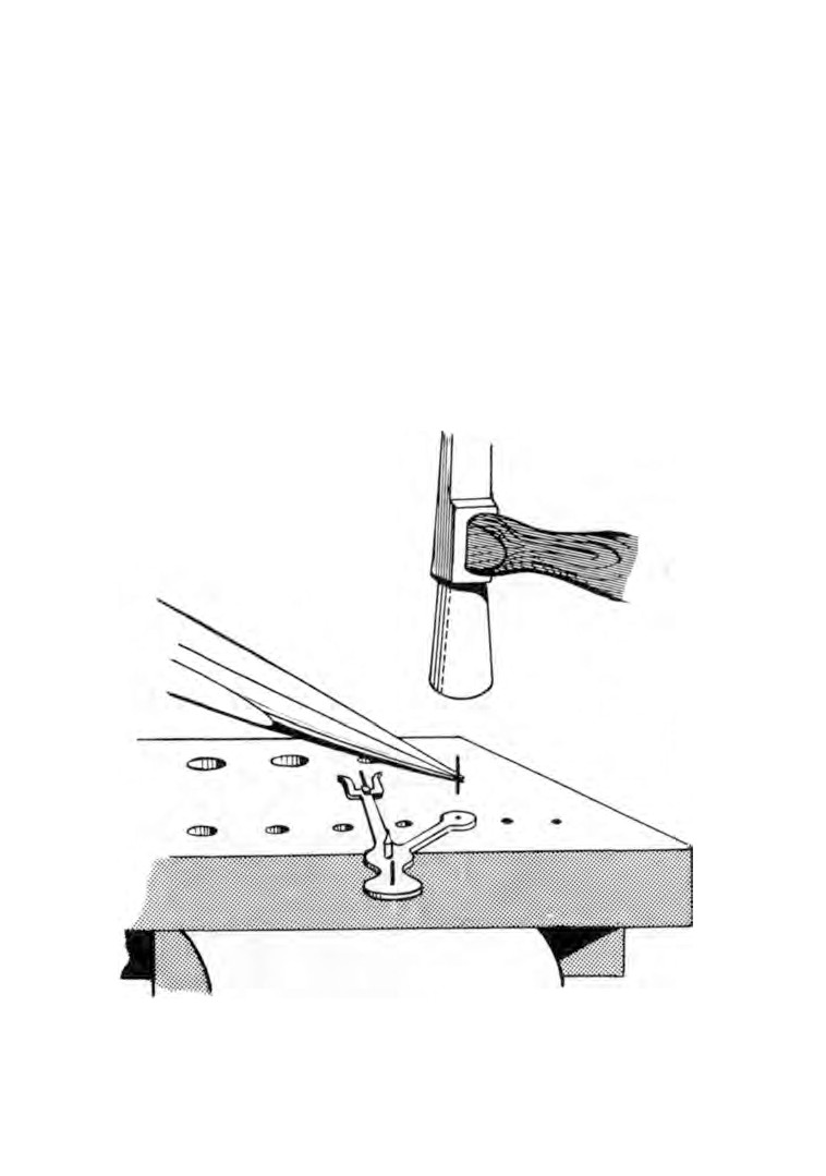
Fig. 49. Closing the pallet arms.
92
WATCH AND CLOCK REPAIRS
Remove the lever and bend the arm sideways using the brass
faced pliers or a made-up tool as shown in figure 48. If the pallets
have no arms, a slot must be cut in the pallet and then carefully
closed by tapping with a hammer (Fig.
49).
If the pallet pins are badly worn they must be renewed before
making adjustments to the escapement.
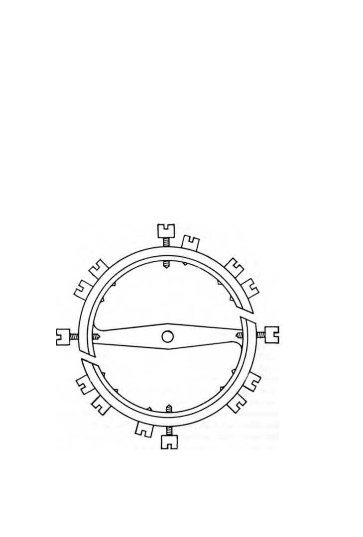
Place the lever over a graduated stake and with a length of
blunted sewing needle gently hammer the old pins out.
The replacement pins can be made from a sewing needle. Select
one that is slightly oversize, cut two pieces to the length required
and carefully hammer them into the pallets over the stake
(Fig.
50).
Fig. 50. Fitting replacement pin.
CHAPTER ELEVEN
Balances
A W A T C H balance consists of a hairspring and collet assembly,
a balance wheel and a roller, all of which are fitted to a common
staff.
If a balance is subjected to a rise in temperature, the wheel
diameter will be increased causing the bulk of the weight to
move away from the centre. This will have the effect of slowing
down the movement. A drop in temperature will have the reverse
effect and the movement will gain.
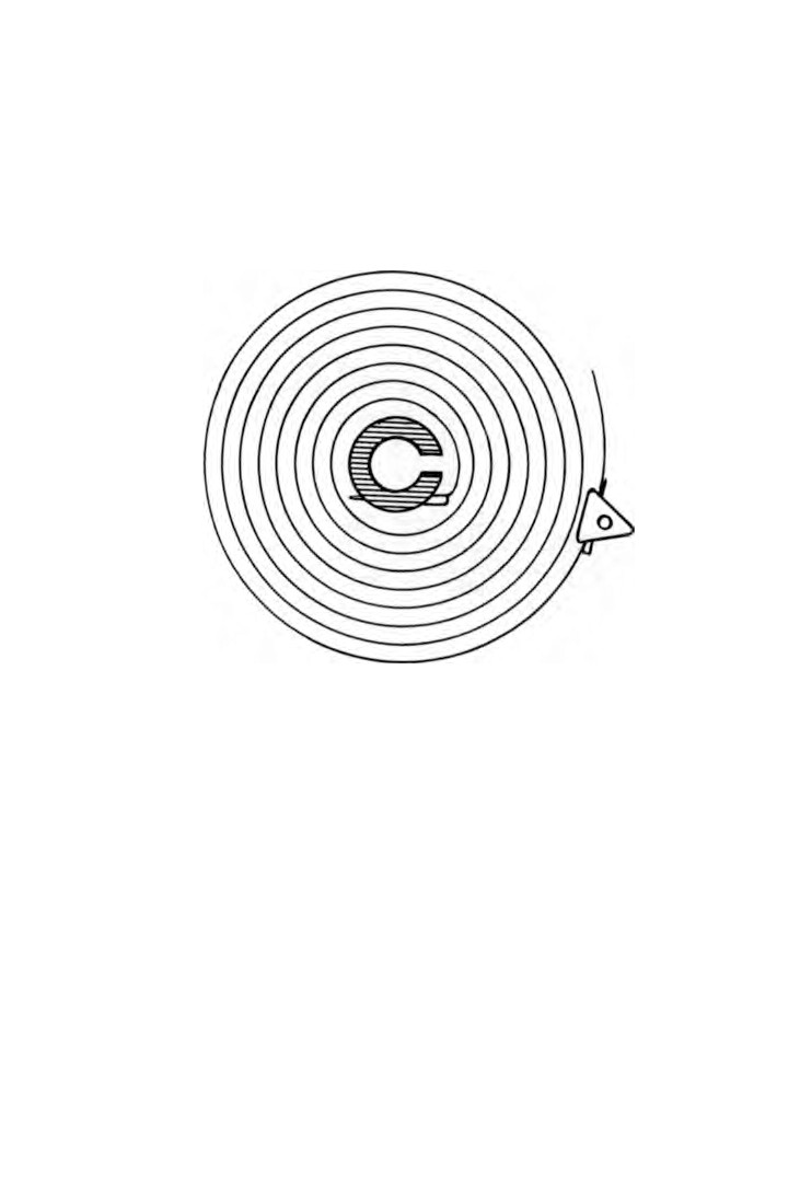
Fig. 51. Compensated balance.
93
94
WATCH AND CLOCK REPAIRS
To overcome this, the more expensive watches are fitted with
a means of compensating for variations in temperature.
Compensated balance (Fig.
51). The wheel is made of steel but
the outer edge of the rim is faced with brass. This is known as
bi-metallic.
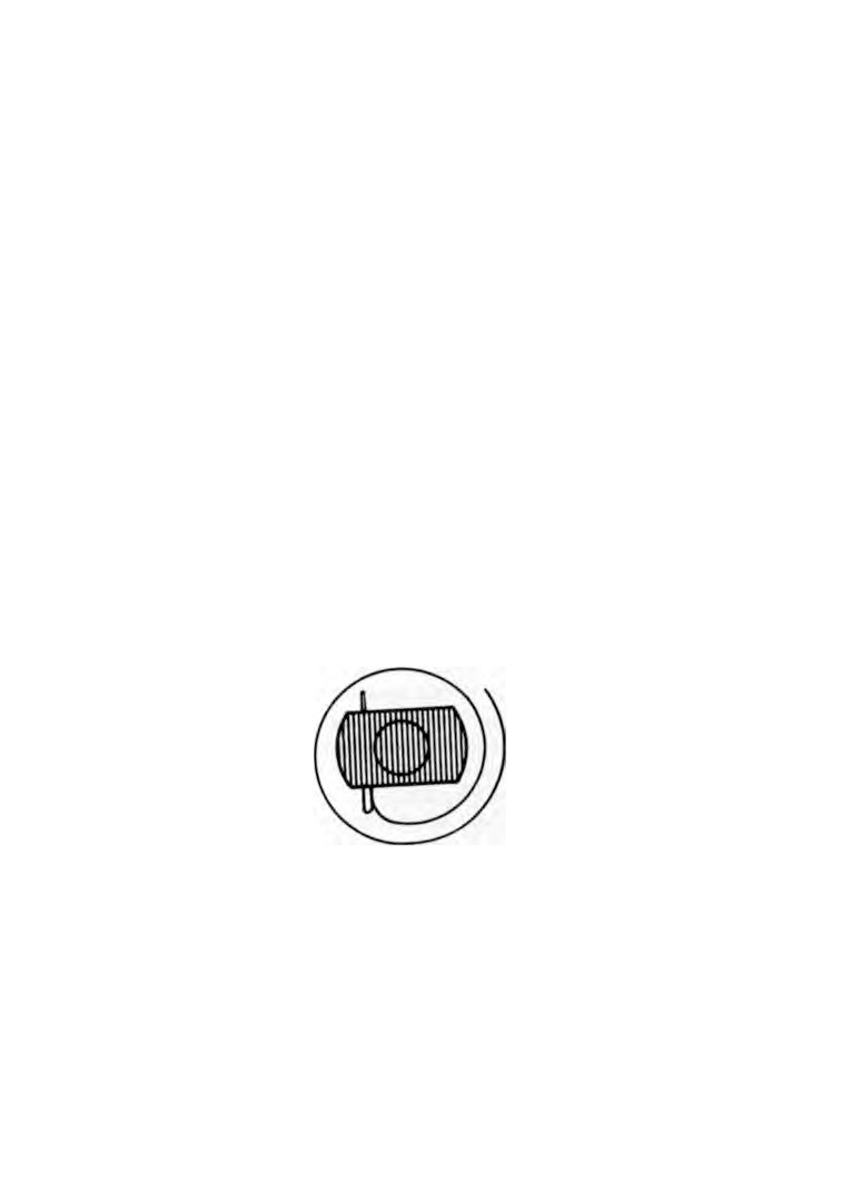
Fig. 52. The hairspring.
The rate of expansion of brass is greater than that of steel
when both are subjected to identical conditions. If a straight
bi-metallic strip was heated, the brass would increase its length
more than would the steel and the bi-metallic strip would curve,
the brass being on the outside.
This is the principle upon which temperature compensated
balances are made. With a rise in temperature the wheel expands,
which would normally slow down the rate of swing. In expanding,
the two halves of the rim curve inward bringing the bulk of the
weight closer to the centre.
If the effect of inward curvature balances out the effect of
expansion, the watch will maintain a constant speed.
BALANCES
95
Provision is made for fine adjustment by fitting screws into
the wheel rim.
Usually it is not necessary to make any adjustment here after
the screws have been set by the manufacturer.
In addition to the compensating screws, there are four quarter
screws placed equidistant from each other. These screws have
longer threads than the compensating screws and are used to
change the speed of the balance.
Unscrewing an opposite pair will slow down the movement
and screwing them in will increase the speed. This is because the
distance from the centre to the bulk of the weight is being altered.
Hairspring
(Fig.
52). The hairspring is made from steel wire
rolled flat and thin and coiled into a spiral. The strength of the
spring will vary according to the width and thickness of the
material. The inner end is pinned to a collet and the outer end
is pinned to a stud.
Most collets are made of brass and shaped in the form of a
split collar or bush. The centre hole is made to fit tightly over the
balance staff. One side of the collet is split to provide springiness.
Some of the best English lever watches have steel collets, they
Fig. 53. Steel collet.
are shaped with two flats, one on each side, and are not split
(Fig.
53). The clearance between the flats and the inner coil of the
spring enables truing of the hairspring to be made more easily.
There are different types of studs in use. One of the most
common types in use is a brass block with a pin machined on one
96
WATCH AND CLOCK REPAIRS
face, the pin being either a push fit in the balance cock or held in
position by a screw entering the balance cock at the side.
The balance staff moves in two jewel bearings, one in the bottom
plate and the other in the balance cock.
A regulator or index is fitted to the balance cock and is free
to move within a restricted arc. The hairspring passes between
two index pins in the index.
When the index is moved from one position to another the
effective length of the hairspring is altered causing the movement
to gain or lose according to the direction in which the index was
moved.
Fitting a flat hairspring. The original hairspring with its collet
must first be removed. Hold the balance between finger and
thumb at each end of the balance arm; holding it this way will
prevent distortion. Push the blade of a steel oiler into the slot of
the collet, this will spring the collet and reduce the grip on the
balance staff. Turn and lift the oiler in one movement and the
collet will be freed from the staff.
If the slot in the collet is too wide for the oiler, a thin knife
blade inserted beneath the collet will lift it from the staff.
It is not advisable to hold a stock of hairsprings because of the
very wide range in use in present-day watches.
Springs are made in varying strengths in different sizes and to
enable your supplier to select the correct spring it will be necessary
to send the count (number of vibrations in one hour), the balance
and the balance cock with your order. We have seen how the
count is calculated in Chapter 6.
On receipt of the spring we must ensure the strength is correct
and to do this the spring is temporarily fitted to the balance and
a count is made.
First, lay the spring on the underside of the balance cock
centrally over the pivot hole. The diameter of the spring must be
sufficient to allow the outer coil to pass through the index pins
of the balance cock and then be pinned in the stud. If the spring is
too large make a note of the approximate position that will be
pinned to the stud.
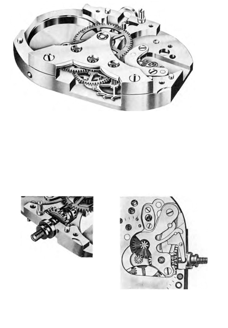
Plate IV: Wheel train and lever in position.
Plate V: Crown wheel
Plate VI: Winding mechanism.
and castle wheel.
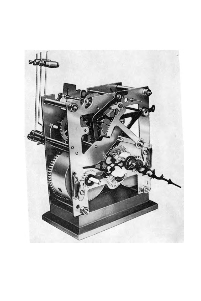
Plate VU: Smiths striking clock.
BALANCES
97
Lower the spring over the balance staff and hold it temporarily
in position by fitting the collet above it. Grip the hairspring in
tweezers at the position where the spring passes through the index
pins. Lift the balance wheel and spring so that the wheel hangs
under its own weight. Lower the balance until the staff just
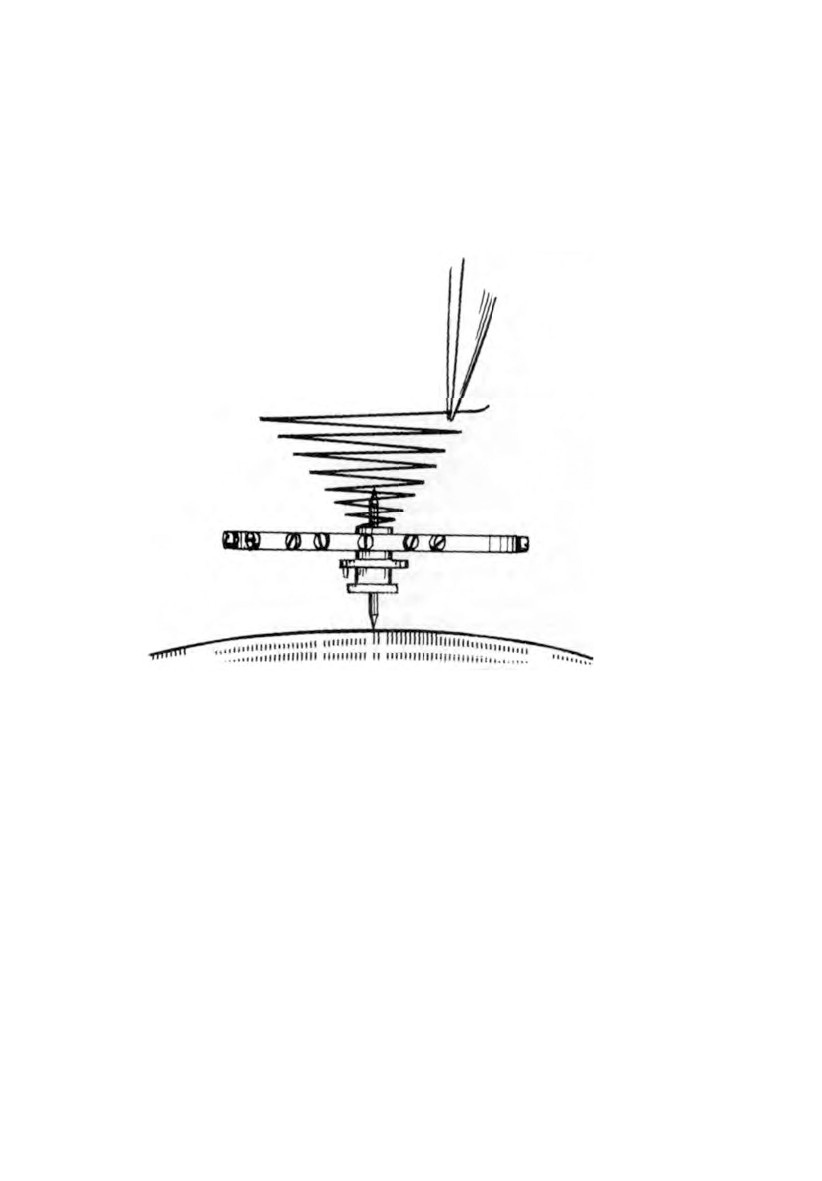
Fig.
54. Method of counting vibrations.
touches the glass of a watch that is fitted with a seconds hand.
With the finger and thumb of the other hand rotate the balance
wheel about half a turn and then release it. Count the number of
double vibrations made in one minute
(Fig.
54). If the correct
spring has been supplied the count will be the same as was calcu
lated for the gear train. Remove the collet and then the spring
from the balance staff.
We are now ready to fit the spring to the collet, but first we will
need a tool to enable us to break off the surplus length of spring.
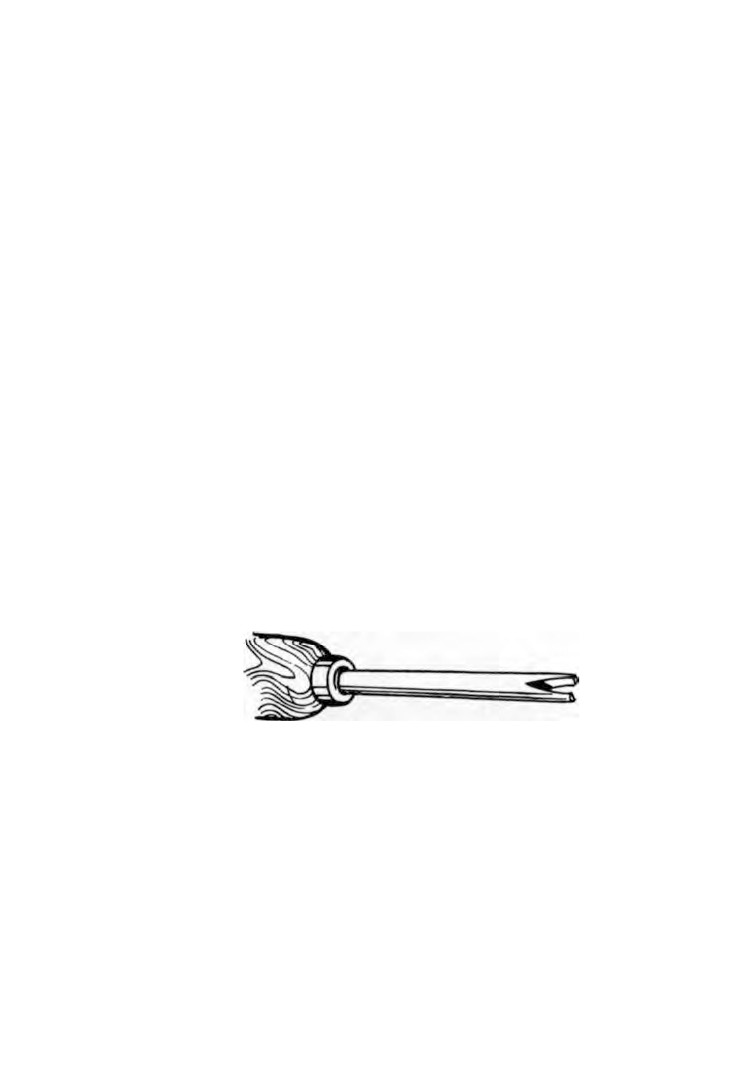
Drive the point of a sewing needle into a slender wooden
98
WATCH AND CLOCK REPAIRS
handle and stone away the top of the needle eye leaving a fork
end (Fig. 55).
Lay the collet on a sheet of stout white paper and place the
spring centrally over the collet. Hold the spring in a pair of
tweezers about a quarter of a turn from the centre. Place the
bending tool over the spring and close to the tweezers. Bend the
short length of spring backward and forward a few times and it
will break away. Repeat this process until sufficient length of
spring has been removed from the centre to allow it to pass
freely over the collet.
Bend the end of the spring inward using two pairs of tweezers
and then straighten it. The length of the spring to be bent inward
is a little more than the length of the pin hole in the collet.
The pin that is going to secure the spring to the collet must now
be made. Take a piece of brass wire, file a taper to fit the collet
and burnish it with the flat burnisher. File a flat down one side
of the pin a depth of approximately one-third of the diameter
of the pin. Polish the flat with the finest emery stick.
Straighten one of the pieces of broken spring and insert it in
the collet. Push the taper pin tightly into the collet with the flat
side against the piece of spring and mark the pin at each end of
the pin hole with a knife. Remove the pin and cut off the piece
between the two knife marks. Polish the ends to remove all burrs.
Fig.
55. Tool for breaking off end of hairspring.
Refit the pin and the piece of spring to ensure that the pin finishes
a little more than half-way through the hole.
A collet holder must now be made. A piece of steel rod is filed
at one end to produce a long taper. Polish the taper with a fine
emery stick and finish with a burnisher.
Lower the collet on to the taper until it just grips. Make sure
it is square with the holder and not at an angle.