Handbook of Watch and Clock Repairs (1972) - page 1
Contents
Preface
7
Part One: G E N E R A L
1
Workbench and tools
9
2
Materials
21
3
The turns and their uses
23
Part Two: W A T C H E S
4
The movement
29
5
Overhauling and cleaning
35
6
Wheel trains
57
7
Hands, dial and motion work
60
8
Keyless work
66
9
Barrels, mainsprings and fusee chains
71
10
Escapements
79
11
Balances
93
12
Shock proofing
103
13
Cases
109
14
Magnetism
113
Part Three: C L O C K S
15
The movement
116
16
Pendulum clocks
119
17
Striking clocks
128
C O N T E N T S
18 Chiming clocks
132
19 Grandfather clocks
136
20 Carriage clocks
142
21 Cuckoo clocks
149
22 French clocks
156
23 Alarm clocks
159
24 Electric clocks
167
Appendix: Mail ordering
170
Index
174
Preface
THERE have been many books written on the repair of watches
and clocks but the majority have been intended for the serious
horologist and the apprentice.
Little has been done to publicize horology as a hobby.
Many will say that to do such a thing is inadvisable without
proper training. But what of the present-day hobbyists who are
self-taught and whose interest in their subject is such that their
knowledge and skill often surpass those whose full-time
occupation it is?
I have known men who, since their youth, have been interested
in radio. Their knowledge and skill today are extensive and
although not qualified in the official sense, nevertheless they have
become authorities on their subject. Similar remarks can be
directed towards other occupations, and so it is with watch and
clock repairing.
In writing this book, I have assumed that the reader has no
knowledge of the subject and I have endeavoured, therefore, to
concentrate on the basic principles rather than advanced work.
An attempt has also been made to show the beginner that quite
a lot of practical work can be done with limited equipment and
a small initial outlay.
In the course of overhauling a movement the beginner will
frequently be confronted with a job beyond his ability and which
requires the use of equipment not in his possession. The appendix
at the back of the book will guide the reader on how to go about
sending work to an outside repairer. Once having established a
contact, no job should be too big or too difficult to tackle.
A little practice at home dismantling and assembling some old
movements will quickly introduce confidence and provide the
reader with the light touch necessary when working on watches.
7
8
P R E F A C E
Appreciation and thanks are extended to Messrs Parechoc
S.A., Le Sentier, Switzerland
(manufacturers of the Kif Flector),
The Universal Escapement Ltd., La Chaux-de-Fonds, Switzer
land
(manufacturers of the Incabloc), and to Erismann Schinz
Ltd., Le Neuveville, Switzerland (manufacturers of the Monorex)
for supplying me with detailed information and drawings of their
shock absorbers.
A special word of thanks is given to Messrs Baume & Co. Ltd,
50 Hatton Garden, London (Longine watches) and Smiths Clocks
& Watches Ltd, Sectric House, Cricklewood, London, both of
whom have been most helpful in supplying information and
drawings.
It is worthy of note here that in my approach to the industry,
I found an unexpected enthusiasm to help when it was known that
the book was to be a hobby book rather than a textbook. It was
considered that such a book was badly needed and all concerned
wished it every success.
Last, but by no means least, my special thanks go to Mr S.
Pleasants who has done so much in producing original drawings
and preparing illustrations for publication, frequently, I might
add, having to alter them as a result of a change in the original
manuscript. For him it was a nightmare gallop keeping pace with
the typewriter keys.
Part One
GENERAL
CHAPTER ONE
Workbench and tools
WATCHES and clocks can be overhauled and simple repairs
carried out without the need of an elaborately equipped work
shop. To begin with, a small rigid table with adequate lighting
will provide the workbench, and the tools can be limited initially
to a selected few to cover general work. More specialized tools
can be obtained later if and when the need arises.
However, it is the intention here to describe typical workshop
conditions and then leave you free to modify these arrangements
to suit your requirements.
A workbench is required, or alternatively a shelf firmly secured
to a wall.
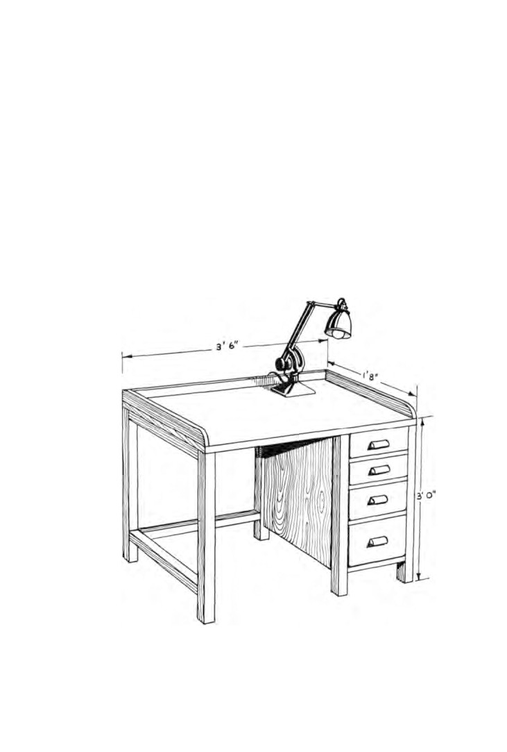
The working surface of the bench should be at least 3 ft. from
the ground (Fig.
1). This will enable close work to be carried out
without bending low, resulting in greater comfort and increased
control. The length of the bench top needs to be about 3 ft.
6 in.
to permit working with both elbows spread out. The width
should be between
18 and 20 in. to allow space behind the work
in hand for small tools and accessories in use.
Strips of wood about 2 1/2 in. wide placed on edge on the top of
the bench along the two ends and along the back prevent items
being knocked to the floor.
A few drawers built under the top for storage of work, tools,
materials, etc., completes the bench.
It is essential that all work be conducted away from dirt or dust
9
10
WATCH AND CLOCK REPAIRS
because the smallest piece of foreign matter in a watch can cause
the movement to stop, and dust will soak up the oil and cause the
movement to dry out.
Sometimes it is quicker and cheaper to secure a shelf to a wall.
A strong, well made shelf securely fitted is much preferred by
many repairers.
Preferably the bench should be situated against a window
facing north. The reflected light obtained is softer and more
suited to this type of work.
If an adjustable electric lamp is mounted on the bench top or
secured to the wall in the case of a shelf, the lamp can be pulled
down close to the work and there should be no fear of eye strain.
Having provided the workbench and the lighting, attention
Fig. 1. Workbench.
WORKBENCH AND TOOLS
11
must now be given to tools. The following list is a guide to the
tools that need to be obtained to start with and to those that can
be purchased when a little more experience has been gained and
the range of work being undertaken has been widened.
INITIAL TOOL KIT
1 pair flat-nose pliers 4 in.
2 cleaning brushes
(medium
1 screwdriver 7 in.
and soft)
1 set watch screwdrivers
1 pin-vice
1 eye-glass 2-in. focus
1 oilstone, fine/medium
1 pair fine tweezers
handles
1 pair heavy tweezers
broaches
2 oilers
rat-tail files
1 oil cup (watch oil)
pillar files
- fine, medium and
1 oil cup
(clock oil)
coarse - 4 and
6 in.
2 pairs hand removing levers
1 vice,
2\ to
3-in. jaws
1 pith holder
1 watchmaker's hammer
SUPPLEMENTARY TOOL KIT
1 pair round-nose pliers 4 in.
1 round-face hammer
1 pair snipe-nose pliers 4 in.
1 brass-faced hammer
1 pair brass-faced flat-nose
1 watchmaker's spirit lamp
pliers
4 in.
1 blueing pan
1 pair top-cutting nippers 4 in.
1 graduated steel stake
1 screwdriver 12 in.
1 flat burnisher
1 double lens eye-glass
1/4-in.
glass dust covers
focus
1 pair turns with accessories
1 eye-glass 3-in. focus
2 clock spring clamps
Too much emphasis cannot be placed on the need to buy good
quality tools. It is better to start with a few good ones and slowly
build up a kit, than to buy poor quality tools that must inevitably
lead to repair work of a low standard. Make your purchases from
firms who specialize in this equipment and who thoroughly
understand your requirements.
12
WATCH AND CLOCK REPAIRS
The application of special tools will be dealt with in the
appropriate chapters, but a few hints on the use and maintenance
of the more common ones may prove helpful at this stage.
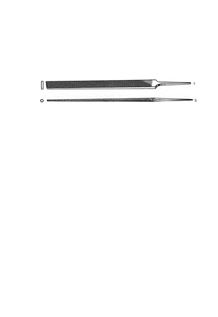
Files. The two most useful types of file for watch and clock
repairing are pillar files and rat-tail files (Fig.
2). Useful sizes are
4 in. and 6 in. in coarse, medium and fine cuts.
Fig. 2. Files, (a) Pillar (b) Rat-tail.
Files are cutting tools and must be treated as such. The teeth
are shaped like those of a saw and consequently cut in one
direction only.
Soft metals such as brass need new files but steels can be cut
better with a part worn file where the tips of the teeth have been
worn down. It follows then that new files commence their life
by being used for brass and are then passed over for use on steels.
It is sometimes more economical to use a double-sided file such
as a pillar file, for both metals, in which case the side used for
brass is marked by passing a piece of white chalk across the teeth.
It is essential that you are able to file accurately and therefore a
little practice may prove worth while.
Place a piece of brass rod horizontally in the vice. Hold the
pillar file by the handle in the right hand. Place the file on the
brass and place the forefinger and thumb of the left hand on the
end of the file.
A forward stroke is now made with just sufficient downward
pressure for the file teeth to cut the metal.
A flat surface can best be obtained by keeping the file hori
zontal. To do this the stroke is made with a light downward
pressure on the file handle and a heavier downward pressure on
the file tip.
As the centre of the file nears the brass, so the two pressures
WORKBENCH AND TOOLS
13
are adjusted until, when the file is equidistant over the brass the
two pressures are the same.
As the stroke continues, the two downward pressures are pro
gressively reversed until, when the file has reached the end of its
stroke, the heavier downward pressure is being made on the
handle and the lighter downward pressure on the tip.
A little practice and it will be found that the knack of maintain
ing these varying pressures will not be difficult.
Pillar files usually have both edges smooth thus enabling one
face of a step to be filed without removing metal from the
adjacent face.
Quite frequently taper pins will have to be made by filing; this
is known as 'pin-filing'.
A small block of fibre or hard wood is needed having in one
face a number of grooves of varying depths. The block is placed
in the vice with the grooves uppermost. A piece of selected brass
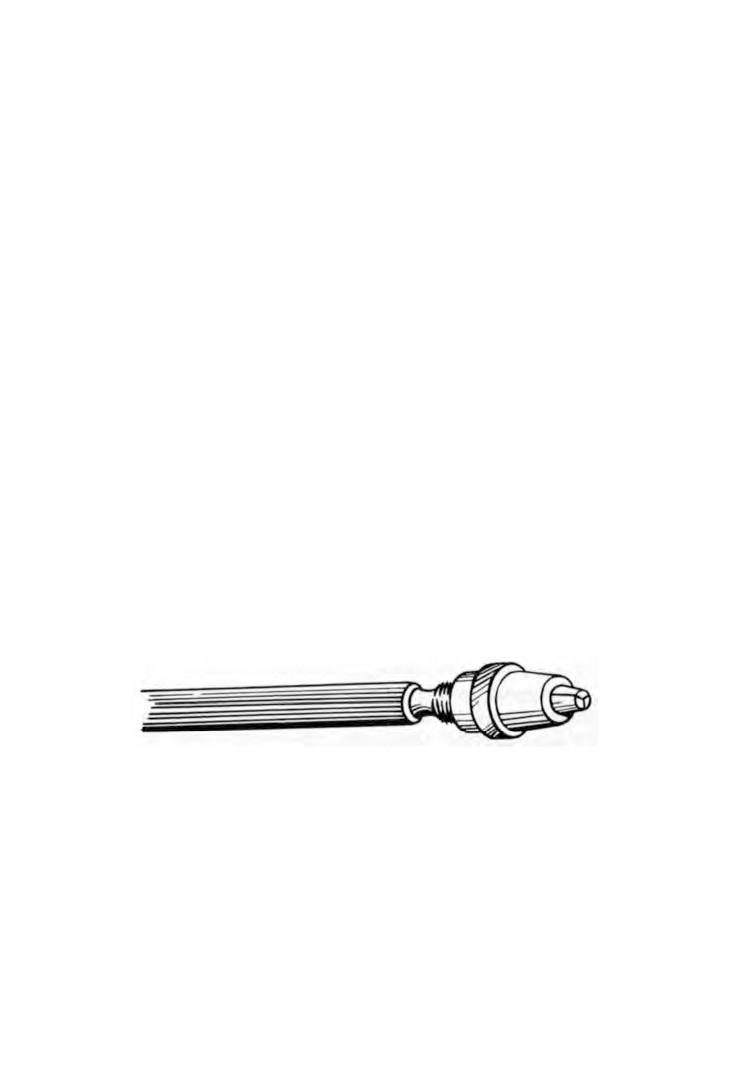
rod or wire is placed in the jaws of the pin-vice
(Fig.
3), the
protruding length dependent on the length of the pin required.
The wire is laid in one of the grooves and held at a slight
downward angle. The groove selected is that which allows the
wire to just stand proud of the surface of the block.
A fine pillar file is selected and a light forward stroke is made.
The right hand can control the file better if the forefinger is
Fig. 3. Pin-vice.
straight and its tip resting on the side of the file. At the same time
the pin-vice is rotated between the forefinger and thumb of the
left hand causing the wire to revolve against the direction of the
file.
When the stroke is completed, the file is drawn back, lightly
resting on the wire to keep the wire in the groove, and the
1 4
WATCH AND CLOCK REPAIRS
pin-vice is rotated in the opposite direction in readiness for
the next stroke.
A little practice and synchronization of movement will be
achieved.
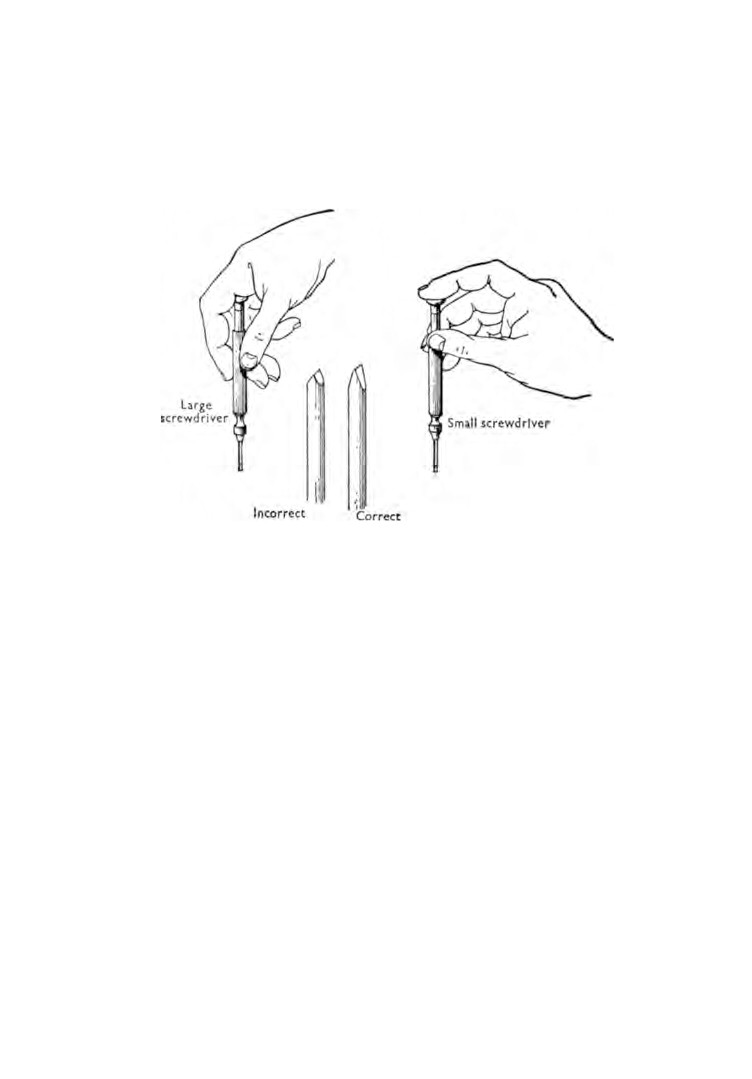
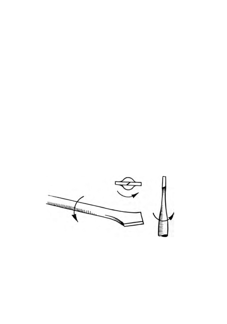
Fig.
4. Correct methods of holding watchmaker's screwdrivers; and
(centre) screwdriver blade.
Watch screwdrivers. These are best purchased as a set of three
or four in a box. The correct method of holding them is shown
in figure
4.
With constant use screwdriver blades need re-shaping. This is
done by using a smooth file. The blade of the screwdriver should
be well blunted and the taper kept long
(Fig.
4). If the taper is
short and the blade end is sharp, the screwdriver will tend to rise
out of the screwdriver slot and damage the screw head.
Oilers. These can be purchased quite cheaply in attractive
plastic cases, but on the other hand they are simple to make
which sometimes proves more satisfying.
Two sizes are required. A small one for jewel holes and a larger
one for general work.
The small one can be made from a sewing needle. Heat the
point to a blue, file two flats opposite each other, place the needle
WORKBENCH AND TOOLS
15
on the vice and tap out the end using the round-face hammer.
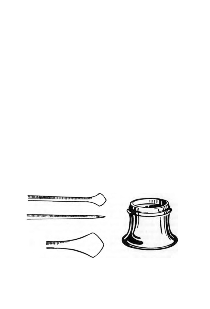
Finish off with a small oilstone. Figure 5 shows an enlarged view
of the shaped end.
The larger one can be made from a short length of steel wire.
Long slender handles are now needed. These can be made from
lengths of wooden rod rounded off at each end.
The method of transferring oil from the oil bottle to the move
ment is accomplished in two stages. First, a large watch screw
driver is dipped into the bottle of oil and one drop of oil is placed
in an oil cup. The tip of the oiler is then placed in the oil resulting
in a small quantity of oil being deposited on the oiler.
The tip of the oiler is then allowed to touch the part to be oiled
and if the oiler is correctly shaped the oil will be transferred by
capillary action.
Eye-glasses. The list of tools includes three sizes of eye-glasses,
a 1/4-in. focus double lens, a 2-in. focus single lens (Fig. 6) and a
3-in. focus single lens. The 1/4-in. is for examining very fine work
such as jewel holes in watches. The 2-in. is for general use when
working on watches, and the 3-in. is for clock work.
The lens holder is fitted into the socket of the eye where it
should remain without discomfort leaving both hands free to
work.
The lens holders vary slightly in diameter and thickness and it
Fig. 5. Oilers.
Fig. 6. Eye-glass.
1 6
WATCH AND CLOCK REPAIRS
is sometimes more satisfactory to try a few glasses for fit before
making a purchase.
If after continual use it is found that the inner face of the lens
tends to steam up, two or three holes about 1/8 in. diameter drilled
through the side of the holder will cure the trouble.
Some repairers prefer to fit head-wires to their eye-glasses. At
least this does prevent the eye-glass from falling at a moment
when a delicate operation is in progress.
A piece of spring steel wire is looped at one end to hold the
eye-glass and the remainder is curved to fit the shape of the head.
The end should reach the back of the head and then be bent into
a small loop to prevent the end from digging in.
For those who wear spectacles, eye-glass holders can be
purchased that will fit the spectacle frames. Your optician will
be the best person to give advice in this respect.
Tweezers. Apart from eye-glasses, tweezers are possibly the
most used tools, particularly in watch repairing. Tool manufac
turers produce wide ranges of tweezers of many shapes, sizes,
qualities and uses and it is therefore sometimes difficult to know
how to make a selection.
It is advisable to start with two pairs of good quality tweezers
for general use. One for light work and the other a little more
robust.
Earlier in this chapter advice was given against buying cheap
tools. This applies particularly to tweezers.
The slightest tendency to twist or reluctance to grip properly
may result in the part snapping out and being lost or damaged.
A good pair of tweezers will pick up a hair between the points
from a piece of glass. It should be possible to place a piece of thin
metal between the points and apply plenty of pressure without the
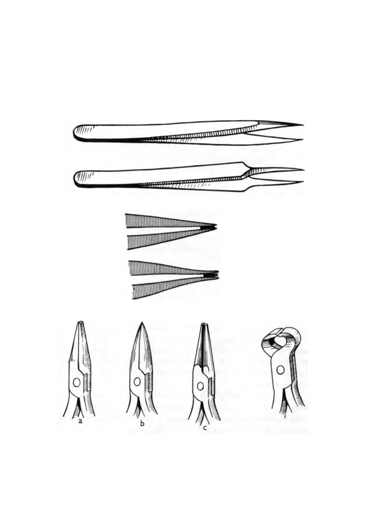
points curling outward. If they do curl outward (Fig. 7), then the
points need trimming. This is best done by using a small oilstone.
If the outward curve is considerable, then the points must be
carefully bent inward using the small flat-nose pliers.
Pliers (Fig. 8). If the serrations on the inner face of the pliers are
too coarse, the tops of the serrations can be removed by filing.
WORKBENCH AND TOOLS
17
The brass-faced pliers are for handling delicate work without
damage or marking.
Top cutting nippers (Fig. 9). These are used for cutting lengths
of wire. Keep the cutting edges sharp by using a medium cut
pillar file.
Fig. 7. Tweezers.
Fig.
8. Pliers, (a) Flat-nose (b) Snipe-nose
Fig. 9. Top-cutting
(c) Round-nose.
pliers.
18
WATCH AND CLOCK REPAIRS
Hand-removing levers. These are essential for removing hands
and are easily made. Two pairs are needed, one fine pair for
watches and a larger pair for clocks.
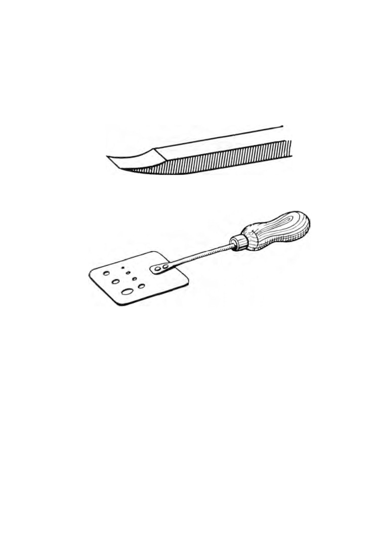
Make the levers from brass as shown in figure
10.
Pith holder. A round metal container about l 1/2 in. diameter
Fig.
10. Hand lifting lever.
Fig. 11. Blueing pan.
and l 1/2 in. deep is required. Place some pieces of lead in the
bottom and melt them down. A layer about 1/4 in. is all that is
needed, enough to make it firm when standing on the bench. Pack
the container tight with pith sticks about
1 1/4 in. long. The ends
of tweezers and watch screwdrivers are kept clean by prodding
them into the pith.
Tools such as files, gravers, etc., must have handles fitted to
them.
Heat the handle end of the tool to a cherry red making sure
that the cutting end is not affected by the heat.
Burn the tool into the handle almost to the desired position.
Hold the tool vertically with the handle downward and strike
WORKBENCH AND TOOLS
19
the vice a few hard blows with the tool handle. This should result
in the handle being firmly in position.
Broaches. When broaching a hole do not use force. Small
broaches can be held in a pin-vice and rotated between the fore
finger and thumb. Larger broaches need thin wooden handles.
When cutting with a broach plenty of lubrication and frequent
clearing of broach cuttings is necessary.
Blueing pan. This is used for blueing polished steel parts The
pan is a piece of brass sheet measuring approximately 1 1/2 in. x 1 in.
and drilled with a row of graduated holes at one end.
To the other end is riveted a short length of steel rod over which
a wooden handle is driven (Fig. 11).
The parts to be blued are placed on the pan which is then passed
through a spirit flame.
As the temperature of the steel parts increases, the surface
colour of the steel changes to blue.
The pan is removed from the flame and the parts are either
dropped into oil or they are allowed to cool off and given a coat
of colourless lacquer.
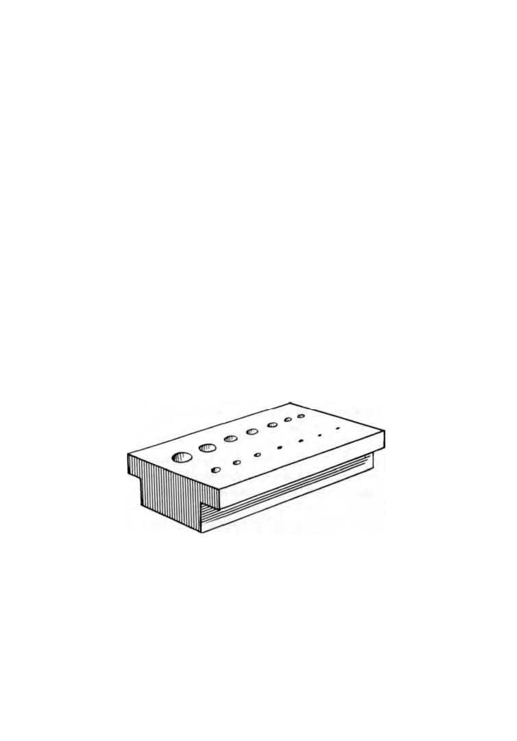
Graduated Stake. (Fig.
12). This is a flat steel block, hardened
Fig.
12. Graduated stake.
and polished, and drilled with holes of different sizes to suit the
work in hand. The under-side is stepped so that it can be held
between the jaws of a vice.
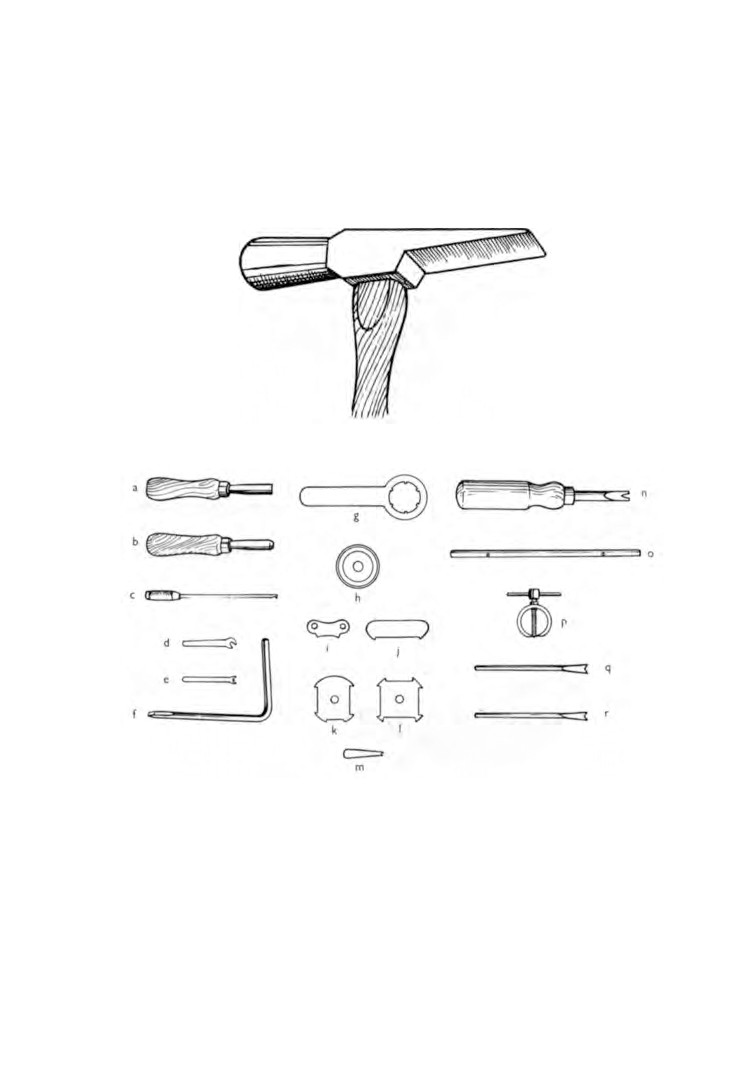
Watchmaker's Hammer
(Fig.
13). These hammers can be
purchased with heads of steel or brass. The steel head is a
20
WATCH AND CLOCK REPAIRS
general purpose hammer, but when the work is more delicate
and the risk of damage greater, a brass head is used.
Finally, a useful set of tools
(Fig.
14) is supplied by Smiths
Clock and Watch Division, London, England.
Fig. 13. Watchmaker's hammer.
Fig.
14. Smith's set of tools,
(a) Case nut spanner, (b) Alarm stop spanner,
(c) 'C' clip remover,
(d) Balance screw key. (e) Hairspring collet adjuster, (f) Bezel remover,
(g) De Luxe 12 ligne case opener, (h) Suction case opener, (i) De luxe
8 3/4 ligne case opener, (j) Yachting timer opener, (k) Empire watch case
opener.
(1) De luxe dustproof case opener,
(m) Empire crown key.
(n) Special screwdriver,
(o) Hexagon nut spanner (8 χ
10 ΒΑ), (ρ)
Circular hand extractor, (q and r) Pair of hand lifting levers.
CHAPTER TWO
Materials
Oil. The lubrication of watches and clocks is done by oil refined
specially for the purpose. Clock oil has a slightly greater viscosity
than watch oil. Both are supplied in small bottles of convenient
size.
In Chapter 5 we shall be discussing the oiling of a watch move
ment and when you realize how very little oil a complete watch
needs, you will then appreciate that even a small bottle will last
a very long time.
When ordering your oil, be it for watches or clocks, buy the
very best. Poor quality oil soon thickens and you will find yourself
dismantling and cleaning the movement all over again.
Make sure it is watch or clock oil. Don't be misled into thinking
that light machine oil will do, no matter how superior the quality
may be.
If the viscosity of the oil is too great for the working parts, the
resistance is going to effect the time-keeping.
Pegwood. Sticks of pegwood are sold in bundles about
6 in.
long. They are used mainly for cleaning out pivot holes. This is
done by shaving one end of a stick to a fine point, inserting the
point through the jewel hole and lightly twisting between the
finger and thumb. Any dirt in the hole will become embedded in
the pegwood. Great care must be taken to ensure that the point
does not break off in the pivot hole. Until experience is gained it is
advisable to examine the pivot hole after this operation to make
sure it is clear. If a piece does break off it can be removed by
inserting the pegwood from the other side.
Methylated spirit. This is used as fuel in the watchmaker's spirit
lamp. When burning, it gives off a clean smokeless flame and does
not blacken or tarnish articles heated in it. This is essential when
tempering steel because of the necessity of watching the colour
change.
21
22
WATCH AND CLOCK REPAIRS
Benzine and Gasoline. As a cleaning agent for watch and clock
movements, benzine is undoubtedly the best. It can be purchased
from a chemist or drug store. A good alternative to benzine is
gasoline, particularly that sold as fuel for cigarette lighters. Both
fluids have a high rate of evaporation and should therefore be
kept in air-tight containers.
W A R N I N G
: Both benzine and gasoline are highly inflammable and
must therefore be kept well away from naked flames. Under no
circumstances have them standing near when the watchmaker's
spirit lamp is in use.
Cleaning fluids. As an alternative to using benzine or gasoline
there are many proprietary cleaning fluids available on the
market. Providing they are supplied by a reputable supplier
these cleaning fluids have much to commend them.
Polishing powders. These are commonly known as crocus
powder, red-stuff and rouge, the only difference being their
fineness of grain. Rouge is the coarsest and crocus powder the
finest. The powder is mixed with oil to produce a cutting paste.
The medium grade is that most commonly used on watches.
Chalk. This is used on the cleaning brushes for cleaning the
movements and to maintain the cleanliness of the brushes them
selves. A convenient form is billiard chalk. It is applied by
stroking the brush over the chalk a few times.
Pith. The cleaning of watch pivots and similar parts is done by
using pith. It is the pith from an elder tree that has been dried,
peeled and prepared in sticks.
Emery sticks. Two pieces of hard wood approximately
5 in. χ
2 in. x 1/2 in. pl a ne d flat b o t h sides are required. F o u r grades of
emery paper ranging from very fine to medium are cut into 2 in.
strips. One strip from each grade is glued to the wood. These
emery sticks, as they are now called, are very useful for reducing
or s mo o t h i n g steel or brass surfaces.
Dial enamel. This is used for repairing white enamel dials. It
has a low melting point and sets hard with a glossy surface.
CHAPTER THREE
The turns and their uses
THERE are two methods of turning. One is to use a lathe and the
other is by means of turns.
Turns are a simple device. Motive power is produced by a
hand-operated bow looped once around a ferrule, and the graver
(cutting tool) is held in the other hand. A little practice is neces
sary to acquire the knack of synchronizing these two movements
and after that, simple turning can be done with a high degree of
accuracy.
The lathe has many advantages over the turns. It is not hand
operated which means both hands are free for the work, and it is
far more comprehensive in the number of operations and func
tions it can perform. Being a precision machine it is easier to
achieve the same degree of accuracy.
The turns consist of two centres and a handrest with a steel or
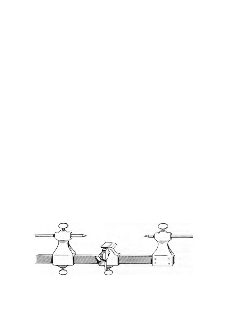
brass beam passing through them (Fig.
15). One of the centres is
secured to the beam at one end, and it is here that the turns are
held in a vice. The handrest and remaining centre are free to slide
and can be locked to the beam in any position.
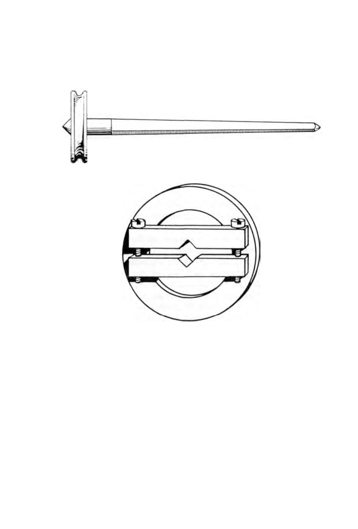
Turning. The work to be turned is placed on a turning arbor
(Fig.
16), or in an adjustable ferrule
(Fig.
17). In both cases the
assembly is supported between the centres.
Fig.
15. The turns.
23
24
WATCH AND CLOCK REPAIRS
The handrest is brought close to the work and locked in
position.
The string of the bow is passed once around the ferrule and the
Fig. 16. Arbor.
Fig.
17. Adjustable ferrule.
bow held in the left hand. A turning graver is held in the right
hand and is placed on the handrest close to the work.
At each downward stroke of the bow the graver is brought up
to the work and a cut is made. The bow is then moved upward
and the graver is moved away from the work just enough to give a
clearance. The process is then repeated.
Turning arbors and adjustable ferrules are supplied in a wide
range of sizes. The bows are supplied in a few sizes and there is a
choice of materials from which the bow-string is made.
When using a turning arbor, a hole is drilled in the metal from
THE TURNS AND THEIR USES
25
end to end which is then broached out smooth. The tapered hole
will now push tightly on to the arbor.
Holding the work by an adjustable ferrule involves the selection
of a ferrule of suitable size and then clamping it to the work.
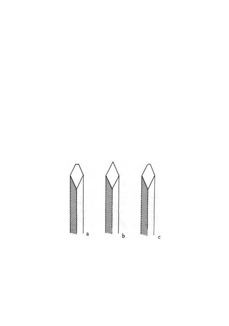
The gravers are made from square or diamond section hardened
steel. The cutting ends are ground as shown in figure
18. The
graver at
(a) is used for roughing down the metal,
(b) is for
finishing off a square shoulder, cuts being made by the side of
the tool as well as the point, and
(c) is used for turning radiused
shoulders.
After grinding, the face is levelled and smoothed on an oilstone,
and finally polished on an Arkansas stone. The side faces are then
held flat on the stone and drawn carefully across to remove any
burrs.
Each graver should be fitted with a wooden handle as described
in Chapter 1.
Having secured the work on an arbor or in a ferrule, it is now
placed between the centres and the centres are brought up into
Fig. 18. Gravers.
position and locked. There should be no end float of the work.
Apply a little oil at each centre.
Adjust the handrest to bring it close to the work. The exact
distance will come with experience. If the distance is too great the
26
WATCH AND CLOCK REPAIRS
graver point will tend to drop and cause chattering. If the hand-
rest is too close, there will be insufficient space to rest the graver
and operate freely.
The height of the handrest must now be adjusted. Cutting is
done by the point of the tool which has to be in line with the
Fig. 19. Turning.
centre of the work. If the graver is too high it will not cut, and if
it is too low it will tend to lift the work and be drawn under. It is
during the downward stroke of the bow that the cuts are made.
Let us assume we have a piece of 1/4 in. diameter brass rod 1/4 in.
long that has been drilled through its length and broached to fit
a suitable size arbor.
The work is mounted between the centres and the turns made
ready for use.
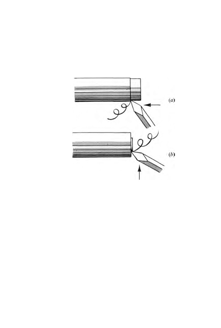
First let us reduce the diameter. The graver is positioned as
shown in figure 19 (a) and must be held quite firmly. A downward
movement of the bow is made and the graver is allowed to just
touch the work at the same time moving slightly to the left. If
the work is not true an indication will be given by the graver not
THE TURNS AND THEIR USES
27
making a complete cut but only removing metal from the high
spots.
The bow is given an upward stroke and the graver is moved
away from the work by means of very slight finger pressure.
Carrying on from where the previous stroke finished, the
operation is repeated until sufficient length of the material has
been cut.
The graver is then returned to the beginning and the metal is
further reduced in diameter.
This process is repeated until the work is revolving completely
true and the diameter has been reduced to the predetermined size.
Now to turn the face. The graver is held as shown in figure
19 (b) and the process of cutting repeated, this time moving the
graver fore and aft.
Brass requires a higher cutting speed than steel and therefore
a longer bow is needed.
Bows are supplied in different lengths and are usually made of
whalebone.
The 'string' is either horsehair that can be purchased in hanks,
or cotton thread coated with beeswax.
Fig. 20. Drill.
There is a tendency for cotton thread to fray and because of
this horsehair is to be preferred.
The tension on the 'string' must allow slip to take place when
looped around the ferrule in case the graver should dig into the
28
WATCH AND CLOCK REPAIRS
work. This acts as a safety device and saves the work from
damage.
Drilling. As with the turning, there are two methods of drilling
in use by watchmakers. Again, one method is to use a lathe and
the other is by bow and ferrule.
To use a lathe is to ensure precision. This cannot be said of
the bow and ferrule method.
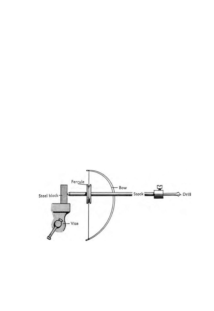
The type of drill used by watchmakers is shown in figure 20,
and it will be seen that cutting takes place in one direction only.
The size of the bow will depend on the size of the drill used.
For the smallest drills a
9 in. bow with horsehair is sufficient.
The selected drill is mounted in a stock and the lock screw
tightened
(Fig.
21). A ferrule is secured to the other end of the
stock to take the bow. The horsehair is so looped around the
ferrule as to rotate the drill in a clockwise direction during a
downward stroke.
The stock centre at the ferrule end is positioned in a shallow
hole drilled in a steel plate held in the vice.
The work is held against the drill and cutting takes place at
each downward stroke of the bow.
Fig. 21. Drilling.
Part Two
WATCHES
CHAPTER FOUR
The movement
A W A T C H movement of high quality is necessarily complicated.
Many hundreds of parts are used, each one cut and fashioned by
craftsmen of unquestionable skill.
Some of these parts are so small they have to be seen under a
powerful magnifying glass before their perfection of design and
manufacture can be fully appreciated.
The term 'movement' applies to the complete watch less the
case and it is measured in lignes.
The ligne was originally a French measure, being
1/12th of a
pouce or French inch. It travelled to England with the French
watchmakers. The ligne was further divided into
12 douzièmes.
The ligne used today by the watch industries in Europe is the
French measure—1 ligne is equal to 2.55883 millimetres. This is
approximately 3/32nds of an inch.
The American watch industry uses a measure originated by
Aaron L. Dennison in
1850 employing a series of numbers with
zero size as a basis. This is equal to 35/30ths of an inch. Move
ments larger than 0 are identified by full integers such as
1,2,
3,
etc. Movements smaller than 0 are identified as
1/0, 2/0,
3/0, 4/0,
etc. Each step is equal to 1/30th of an inch.
There is a further complication that jewellers also use lines,
but the jewellers' line is 1/40th of an inch.
The use of the ligne or line as a measure is not consistent with
modern manufacturing methods and a number of watch manu
facturers have changed over completely to millimetres.
29
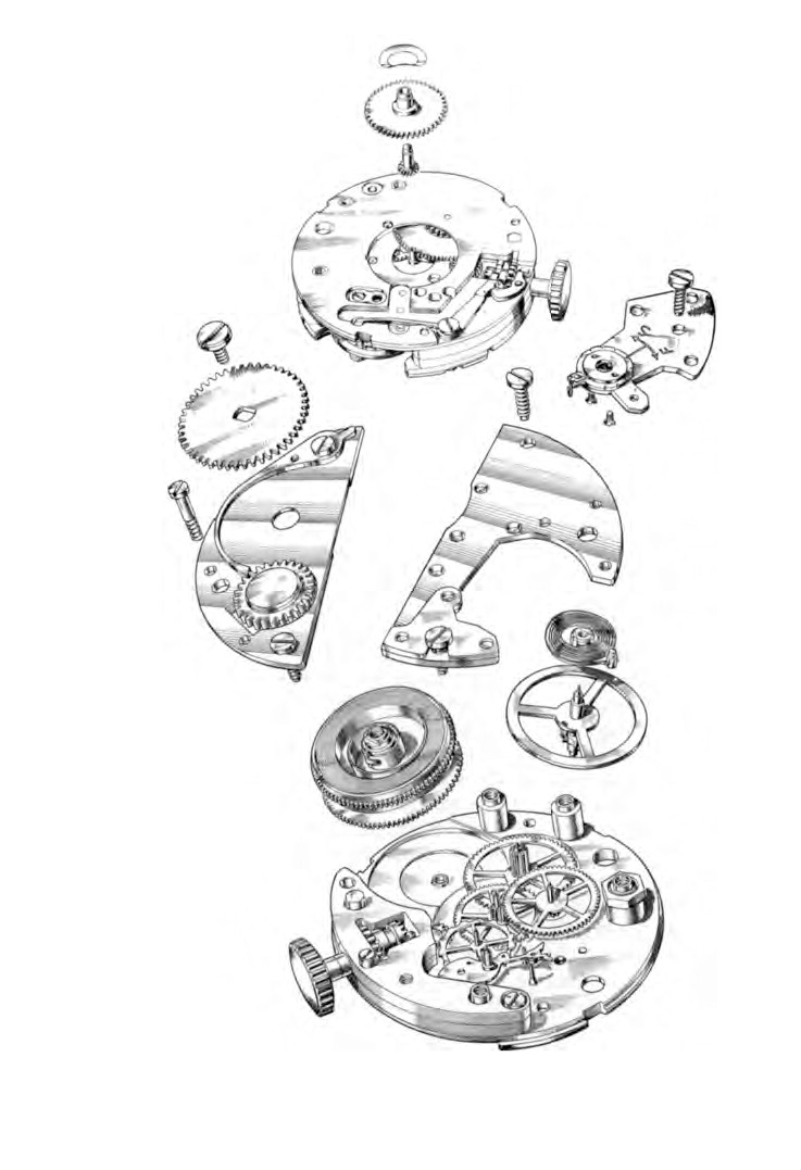
Fig.
22. Exploded view of general construction of inexpensive men's wrist-
watch movement.
THE MOVEMENT
31
Figure
22 illustrates an inexpensive men's wristwatch fitted
with a pin pallet escapement.
A watch movement consists of a train of wheels with power at
one end to drive them, and a means of controlling their speed at
the other end
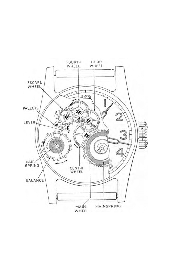
(Fig.
23). To this is added the motion work and
hands to register the wheel train speed on a dial.
Fig. 23. Wheel train and balance.
32
WATCH AND CLOCK REPAIRS
It is of interest to note that most wheel or gear trains in common
use are designed to reduce speed and increase power. In mechanic
ally powered timepieces the reverse is the case.
Motive power. Power is provided by a mainspring coiled in a
barrel. The inner end of the spring has a rectangular hole known
as the eye. This is hooked to an arbor in the centre of the barrel.
The outer end of the spring is hooked to the inner face of the
barrel side. The mainspring occupies about one-third of the
space inside the barrel. The action of winding a watch spring
causes the arbor to rotate and the inner end of the mainspring to
wind itself round the arbor.
There are three methods of using the mainspring to drive the
wheel train and they are known as the going barrel, the stationary
barrel and the fusee.
The going barrel. Gear teeth are cut on the outer edge of the
barrel and this is known as the main wheel. The arbor is squared
at one end to receive a key or a ratchet wheel. During the process
of winding the spring, the spring tension is held by a ratchet known
as the clickwork.
When the movement is functioning, the arbor remains station
ary and the barrel rotates around it.
The stationary barrel. This method will be found mostly in
American watches. The barrel remains stationary and the arbor
revolves in the centre. At one end of the arbor is fitted a toothed
wheel.
The fusee. The time-keeping of old watches was affected by the
drop in power when the mainspring ran down, and so a means of
compensation was necessary. This compensation was accom
plished by the introduction of the fusee.
A cone-shaped pulley was positioned next to the barrel. The
pulley had a spiral groove machined in its face in which a chain
was placed. One end of the chain was hooked to the base of the
cone and the other end of the chain was hooked to the outer face
of the barrel side.
Gear teeth were cut on the bottom edge of the cone and formed
the main wheel. When the mainspring was wound, the chain was
THE MOVEMENT
33
pulling on the smallest diameter of the cone with minimum
leverage.
As the spring unwound itself and the power became pro
gressively less the chain was being transferred from the fusee and
was winding itself on to the barrel. This caused the chain to pull
on an ever increasing diameter of the cone with a proportionate
increase of leverage. By this method suitable compensation was
achieved.
The wheel train. The teeth of the main wheel mesh with the
leaves of the centre wheel pinion. In the same way the centre
wheel meshes with the third wheel pinion, the third wheel meshes
with the fourth wheel pinion, and the fourth wheel meshes with
the escape wheel pinion.
The centre wheel rotates once every hour and therefore carries
the minute hand. The fourth wheel rotates once every minute and
so carries the seconds hand.
The escapement. Some means of controlling the speed of the
wheel train is now required. This is done by the escapement which
consists of an escape wheel, a lever and a balance.
The balance is to a watch as a pendulum is to a clock. The
balance wheel is mounted on a staff that has a very fine pivot at
each end both of which operate in jewel pivot holes.
The fitting of a spring to the wheel provides self-contained
motive power enough to cause the wheel to vibrate many times
before coming to rest. The more accurate the balance and the
lower the frictional resistance at the pivots, the greater will be
the number of vibrations performed by the balance.
The escape wheel is controlled by the balance through the
lever. One end of the lever is fitted with two pallets which allow
the escape wheel to revolve one tooth at a time.
When a tooth of the escape wheel comes into contact with one
of the pallets, that end of the lever is pushed sideways which
causes the other end to transmit a small impulse to the balance.
It is this small impulse caused each time the escape wheel
moves that prevents the balance from slowing down and
stopping.
34
WATCH AND CLOCK REPAIRS
It will be seen therefore that the wheel train moves in a series
of jumps.
To ensure sustained accuracy of time-keeping, each part of the
movement must be machined with precision, all pivots finely
polished, all friction surfaces adequately lubricated, and the
movement must be enclosed in a dust and moisture-proof case.
Everything possible must be done to reduce friction to a
minimum. So-called jewels are fitted as pivot bearings. These
jewels derive their name from the time when watchmakers used
rubies. This practice no longer applies, instead a synthetic material
of equal hardness is used.
The number of jewels used in a watch varies with the quality
of the movement. The usual number is 7,
15,
17 or 21.
The seven-jewelled movement indicates that only the escape
ment is fitted with jewels. The majority of jewelled watches have
fifteen jewels which takes them up to the third wheel.
In addition to jewels being used as bearings for wheel pivots,
they are also used as caps for the balance wheel pivot bearings,
these are known as end-stones.
After a movement has been oiled, jewels and end-stones retain
the oil by capillary action.
The train of wheels and the escapement are supported by two
plates known as the bottom plate which is beneath the dial, and
the top plate. Sometimes the top plate is dispensed with and a
number of bridge pieces or cocks are used instead.
Between the bottom plate and the dial is the motion work. This
consists of a cannon pinion, an hour wheel and a minute wheel.
Winding mechanisms. There are three types of winding mechan
isms. Early watches were supplied with separate keys, and were
wound through a hole in the back.
Modern watches are keyless, the winding mechanism being part
of the movement.
Lastly there is the automatic type. The action of moving one's
wrist causes a weight to swing which in turn winds the main
spring. Overwinding is prevented by a slipping clutch mechanism.
CHAPTER FIVE
Overhauling and cleaning
IF a watch develops a fault then it must be traced and put right.
If the movement is clean and oiled there is usually no need to
carry out any additional work other than check the watch for
time-keeping.
In this chapter we are going to discuss generally the complete
overhaul and cleaning of wristwatch movements. The remain
ing chapters in this section deal with specific assemblies of parts
in greater detail and must therefore be read in conjunction with
this chapter.
Plates I to VI are those of a
5 1/4 x 8 3/4 ligne 15-jewel lever
movement. They serve to show the sequence of assembly of the
parts in a modern wristwatch and the identification of parts
by name.
Too much emphasis cannot be placed on the need for careful
inspection as the work of dismantling continues. A great deal of
conscientious work can be put into the inspection and cleaning
of individual parts after dismantling but when the movement is
once again assembled the original fault may still be there. If the
history of the watch is unknown to you then it must be borne in
mind that some of the parts may not be the originals and that
incorrect replacements may have been fitted or that bad fitting
may have taken place. Before opening the case examine the watch
closely. Frequently much useful information can be obtained
that might otherwise have remained obscure.
Methods of opening watch cases are dealt with in Chapter
13
and you are advised to read this before proceeding any further.
If when the case has been opened a considerable amount of
dust is found inside, then the case needs some kind of
attention.
Operate the hand-set and turn the hands in the normal direc
tion and listen for fouling against the glass or dial. With a keyless
35
36
WATCH AND CLOCK REPAIRS
watch it should be possible to pull the winding stem out and push
it in without undue force or looseness. The feel of the action
should be smart and positive. Test the side-shake of the winding
stem. There should be just sufficient to prevent binding when being
operated. This is very important because a loose fitting winder is
an open invitation to dirt and dust to enter the movement.
Examine the case for signs of it having been dropped or knocked.
A blow on the case frequently results in broken balance pivots if
shock absorbers are not fitted. Remove the glass and inspect it
for signs of fouling by the hands. Carry out the same inspection
on the dial. The most likely fault will be fouling by the tip of the
minute hand. Lightly touch the hands and apply side pressure to
see if they are loose.
Operate the hand-set and hold the watch so that it can be
viewed from the side, turn the hands and observe their movement.
This will disclose any tendency to foul the dial and to foul them
selves. When carrying out this check make sure that the dial is
flat with the bottom plate and is firmly secured.
With the aid of an eye-glass inspect the seconds hand to see if it
is free of the dial face and that there is clearance between the
seconds hand pipe and the hole in the dial.
If when turning the hands it is noticed that the tip of the
minute hand rises and falls, this is an indication that the centre
wheel is not upright. But if the minute hand rotates at a constant
height above the dial and the hour hand rises and falls, then the
centre arbor can be suspected of being bent.
The centre arbor can easily be checked by spinning it between
a pair of callipers. If the arbor is bent, lay it on a flat steel stake
and lightly tap it with the peaning end of the watchmaker's
hammer.
To correct the uprightness of a centre wheel necessitates one of
the centre holes being bushed. This calls for the use of equipment
that is unlikely to be in the possession of a beginner, e.g. a lathe
and a punch and stake. In this event the work of bushing will have
to be sent away.
We now check the hour wheel to make sure that it has some
///////////////////////////////////////