Handbook of Watch and Clock Repairs (1972) - page 4
BALANCES
99
Hold the hairspring in tweezers, lower it over the collet, insert
the inner end of the spring into the collet keeping the spring level
and central with the collet.
Insert the taper pin into the collet until the spring is just
gripped. Push the collet from the holder and lay the spring on the
white paper. In this way the coils of the spring can be checked
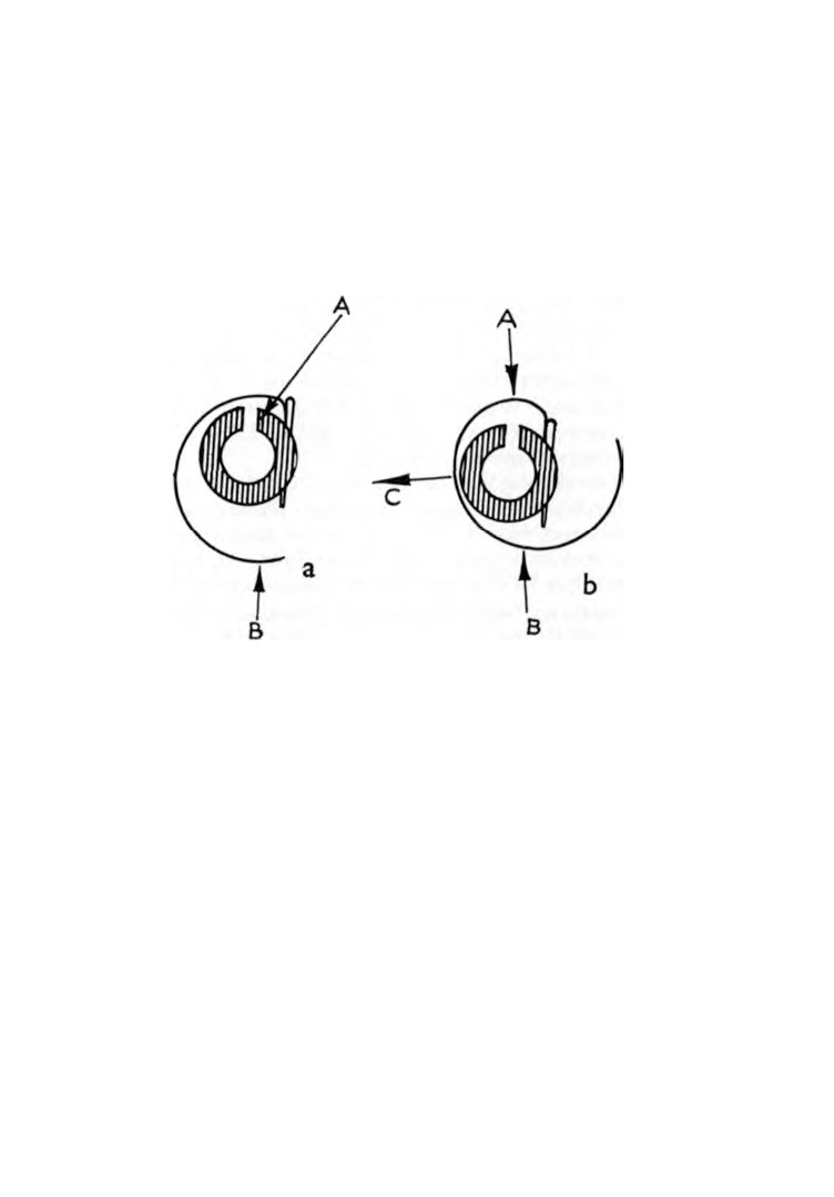
Fig. 56. Centralizing the hairspring to the collet.
t o m a k e sure t h a t they ar e central a b o u t t h e collet. If they ar e n o t
central the spring must be carefully bent to make them so (Fig.
56). All bending should take place within the first quarter coil
from the collet.
In figure 56, a, an oiler is inserted at A a n d given a twist. This
will push the coil away from the collet at that position but at the
same time bring it closer to the collet at B. In figure
56, b, the
diameter of the coil is reduced by applying tweezer pressure
across A and Β causing the coil to move away from the collet at C.
Before making any alterations study the contours of the spring
carefully and decide exactly where the spring needs bending to
produce the desired result. Two pairs of fine pointed tweezers are
best for this operation.
100
WATCH AND CLOCK REPAIRS
To check for flatness of the spring the balance is mounted on
an arbor and is spun between callipers or turns. If the spring is
out of true it can be corrected by gripping it with tweezers close
to the collet and turning in the required direction. Providing the
pin was not put in too tightly the pin will move round with the
spring. Slowly spin the balance after making each adjustment to
check the result. When the balance can be rotated once with no
variation of the spring, the arbor can be removed.
Press the pin firmly into the collet using a strong pair of
tweezers. It is essential that there should be no movement of the
spring in the collet when the pinning is finished.
The next step is to pin the outer end of the spring to the stud.
Make a taper pin in exactly the same way as we did for the collet,
but this time the taper must be longer.
Move the index to the midway position. Lay the balance cock
on the bench with the index pins uppermost. Place the spring on
the balance cock with the collet centrally over the pivot hole and
note the position where the stud will be. Break off the surplus
length of spring allowing for a little to protrude beyond the stud.
Remove the spring and fit the stud to the balance cock. Replace
the spring on the balance cock and pass the end through the pin
hole in the stud. Push the pin into position. Examine the assembly
closely to make sure that the spring is supported parallel to the
balance cock. If it is not, turn the pin which is still in the pin-vice
and the spring will move with it. When the spring is parallel,
make the pin a short distance from the stud with a knife and
break the pin off. Push home tightly with strong tweezers.
The position and shape of the spring may now need altering.
The outer coil must lie naturally between the index pins without
side pressure or side play. If necessary the pins must be bent
closer together. The second coil must not foul the inner index
pin or stud, and the collet must rest centrally over the pivot hole
in the balance cock.
It is sometimes found that the position of the stud is a little too
far from the centre and this causes the spring to be out of centre.
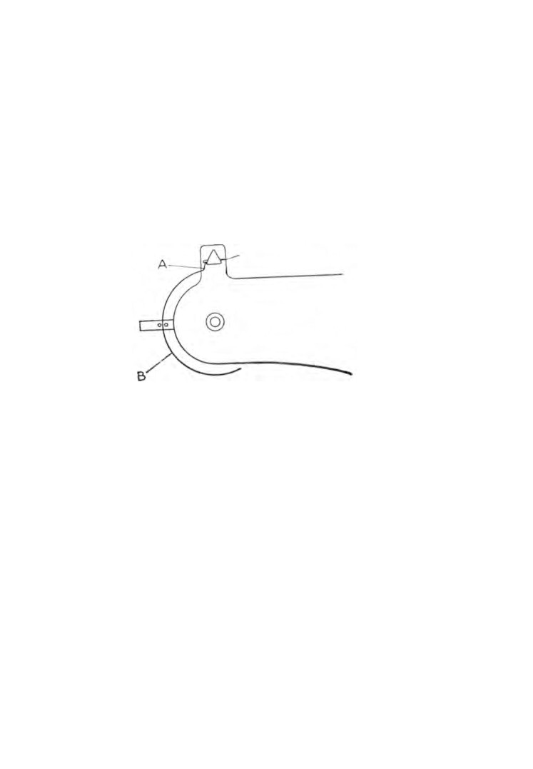
To rectify this fault bend the spring close to the stud at A in
BALANCES
101
figure
57. If the spring touches one of the index pins, bend the
spring at Β in figure
57 until the coil lies naturally between the
pins.
The balance can now be fitted to the movement, the movement
set in motion and a final check carried out to ensure that the
spring is functioning correctly and that no fouling is taking place.
Repairing a hairspring. Once a spring is damaged the most
satisfactory repair is to fit a new one, but there are circumstances
when an attempt to straighten a bent hairspring is justified.
Fig. 57. Centralizing the hairspring and collet to the jewel hole.
Sometimes a spring becomes entangled. If it is caught on the
stud careful manipulation will often restore the spring to its
correct position. If this is not possible, the pin must be removed
from the stud, the spring withdrawn and, commencing from the
centre with a needle, the spring must be followed throughout its
length disentangling as you go.
I f the spring h a s j u m p e d over t h e r i m of t h e balance wheel, t h e
spring must be released from the stud, the collet must be removed
from the staff and the spring rotated in order to unwind itself
from the balance.
A spring can be o u t of true either in t h e r o u n d or in the flat.
That is to say the coils no longer conform to their original shape
or the spring is no longer flat.
Remove the spring complete with collet and lay it on a sheet of
stiff white paper. Follow the coils round with a needle starting
102
WATCH AND CLOCK REPAIRS
from the centre. At the first irregularity of curvature bend the
spring correctly with the point of a needle holding the spring in
tweezers. Continue this process until the outer end of the spring
has been reached.
Now the spring must be checked for flatness. Hold the spring
up and look on its edge. Any upward or downward bends will be
immediately apparent. Once again starting from the centre note
each irregularity and bend the spring back into shape using two
pairs of tweezers.
Having restored the flatness of the spring we must now be sure
that it lies parallel to the collet. To check this, fit the collet to a
turning arbor and rotate the arbor in the turns. Correction can
be made by a slight twist to the spring as close to the collet as
possible.
All that remains now is to check that the spring is parallel and
central with the balance cock. Fit the spring to the stud, ensure
that the outer coil rests naturally between the index pins and that
the collet is central over the balance staff pivot bearing.
Renewing index pins. If a hairspring is subjected to shock it
sometimes jumps from between the index pins or the second coil
jumps in. To prevent this, the index pins should be as long as
possible. If the tops can be turned inward slightly so that they
both meet then isolation of the outer coil will be maintained.
Old pins are cut off and filed down flush. The stumps are driven
out by a blunted needle with the index on a stake. The new pins
are made with a very slight taper, polished with the fine emery
stick and finished with a burnisher. The pins are then pushed
tightly into the index and cut off to length.
CHAPTER TWELVE
Shock proofing
THE parts of a watch most likely to suffer from shock are the
pivots of the balance staff. The diameter of these pivots is
approximately the same as that of a human hair. To knock or
drop a watch imparts shock to the movement and invariably
some damage is caused to the balance staff pivots.
If the shock is severe, at least one pivot will break off and the
watch will stop. A less severe shock is likely to cause one or both
pivots to bend. This damage may not be sufficient to prevent the
movement from functioning but it most certainly can cause bad
Fig.
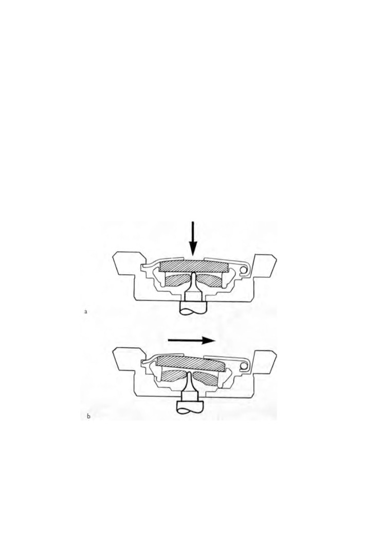
58. Diagrammatic sketch of Kif Flector device, (a) Axial shock,
(b) Radial shock. Under the effect of a shock the balance wheel is
displaced, its pivot carrying away the jewel in-setting and end-stone.
The shock is absorbed by the part of the staff or the arbor which hits
the block. After the shock the spring instantly replaces the whole in its
initial position.
103
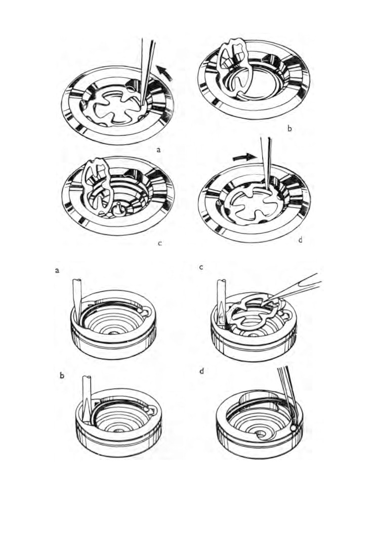
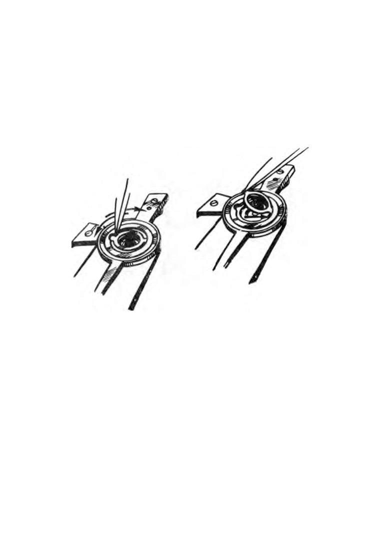
Fig. 59. Kif Flector. Removing end-stone and setting jewel.
Fig. 60. Disassembling Kif Flector.
SHOCK PROOFING
105
time-keeping and also excessive and irregular wear to the pivot
bearings.
Spinning a balance staff between callipers and inspecting
through an eye-glass will reveal any such damage.
It seems obvious, therefore, that some means of absorbing the
shock is required. This in fact has been done and the principle
employed is to use mobile pivot bearings that automatically take
up a position of alignment under spring pressure
(Fig.
58).
Two housings are employed. One is fitted into the balance cock
and the other into the bottom plate. In these housings are
assembled the jewels, the end-stones and the springs.
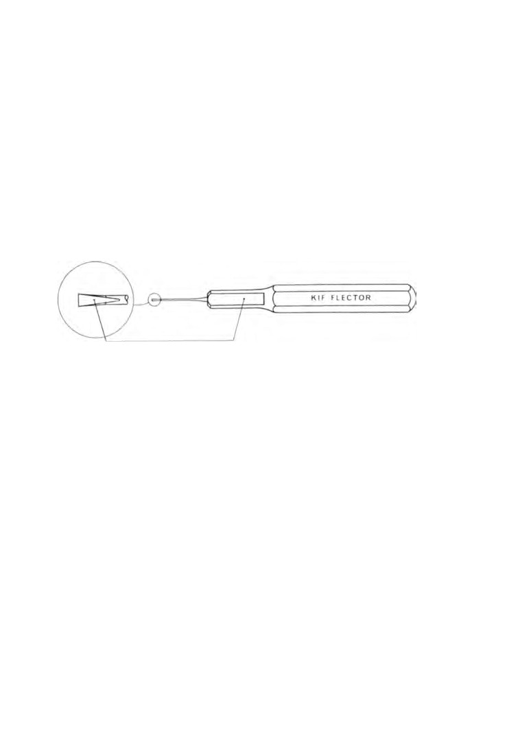
Fig. 61. Kif Flector special tool. The mark on the handle indicates the
flat side of the point.
Shock will cause the balance to move from its normal position.
The pivots will move the pivot bearings until the balance staff
hits against the housings, and the housings and the balance staff
will absorb the shock. The springs then return the assemblies to
their positions of alignment.
Three of the more popular methods used have been selected
and are described in the following paragraphs.
Kif Flector (Fig.
59). A pointed tool is inserted into the spring
notch and the spring is turned in the direction of the arrow
(a).
The spring can now be hinged upward allowing removal of the
end-stone and the setting jewel
(b). The setting jewel and end-
stone can now be cleaned, and the balance staff pivot is suffici
ently exposed to be cleaned
(c). Setting jewel and end-stone are
replaced. The spring is hinged downward and the pointed tool
is used to lock the spring by turning it in the reverse direction (d).
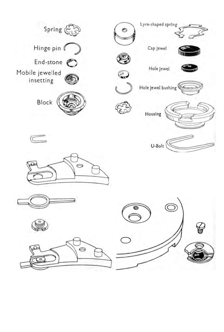
Fig. 62. Exploded view of Kif Flector.
Fig. 63. Exploded view of
Incabloc assembly.
Fig. 64. Assembling the Incabloc
Fig. 65. Assembling the Incabloc
into the balance cock.
into the dial plate.
SHOCK PROOFING
107
The method for dismantling the Kif Flector is illustrated in
figure
60.
The special tool
(Fig.
61) is inserted behind the hinge pin
(a).
The tool is then rotated a quarter of a turn to push the hinge pin
Fig.
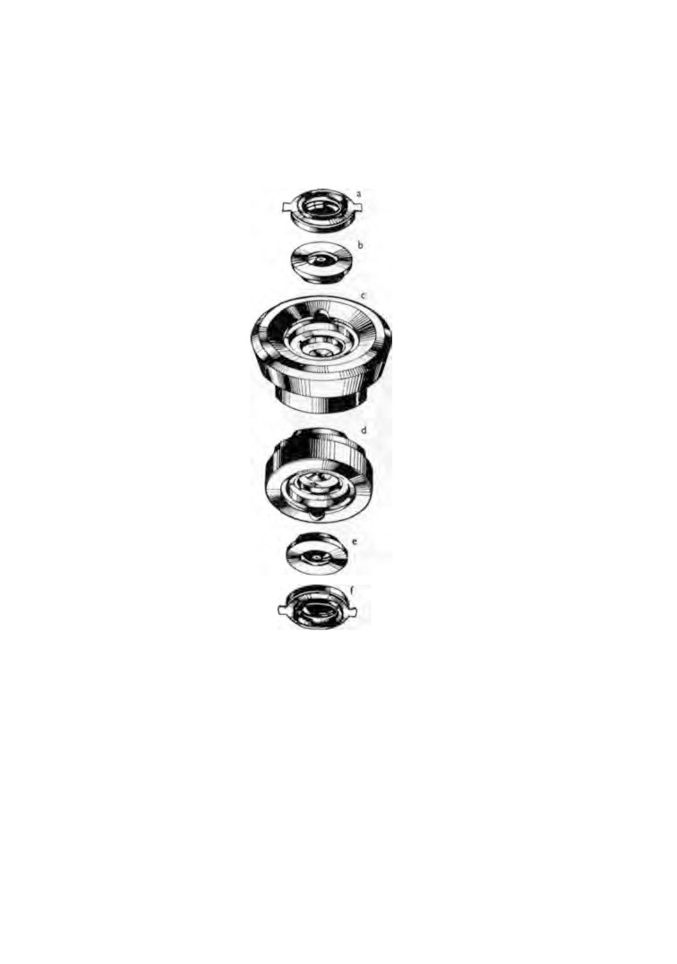
66. Exploded view of Monorex. (a) Cap jewel in setting with cap
jewel spring, (b) In-setting with jewel for balance, (c) Upper end-piece
without fittings, (d) Lower end-piece without fittings, (e) In-setting with
jewel for balance, (f) Cap jewel in setting with cap jewel spring.
inward
(b). The spring is held by tweezers, unhooked from the
hinge pin and removed
(c). To remove the hinge pin from the
block, one arm of the pin is first removed from its groove and
the pin can then be lifted out
(d).
Figure
62 shows the parts in their order of assembly.
Incabloc
(Fig.
63). To dismantle, the spring must be swung
108
WATCH AND CLOCK REPAIRS
clear. Press the ends towards the centre and raise the spring on
its hinge. The jewel cap, the jewel and the jewel bushing can now
be lifted from the housing.
In the case of the upper assembly the housing is secured to the
balance cock by a U-bolt underneath
(Fig.
64). The lower
assembly housing is secured to the bottom plate by a screw
(Fig. 65).
Fig.
67. Monorex shock absorber. Removing the jewel and bushing.
Monorex
(Fig.
66). The end cap is removed as shown in
figure
67. The jewel and bushing can then be lifted from the
housing. Both upper and lower housings are press fits into the
balance cock and bottom plate respectively.
One of the features of these three systems is the ability to
expose both balance pivots without disturbing the balance
movement. This enables the pivots to be cleaned as well as the
shock absorber parts.
Oiling the pivots is accomplished by placing a drop of oil on
the inner face of the end-stone and placing the end-stone and jewel
together. They are then lowered into their housings and secured.
CHAPTER THIRTEEN
Cases
CASES are made of gold, silver, stainless steel or plated brass.
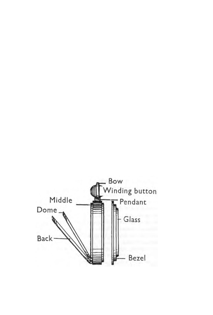
Typical designs are illustrated in figures
68 and 69.
Pocket watch cases. Bezels are snapped on to the case middle.
Domes are either hinged to the base of the middle or are fixtures
and do not open, some cases have no domes. Backs are either
hinged to the base of the middle or they are snapped on.
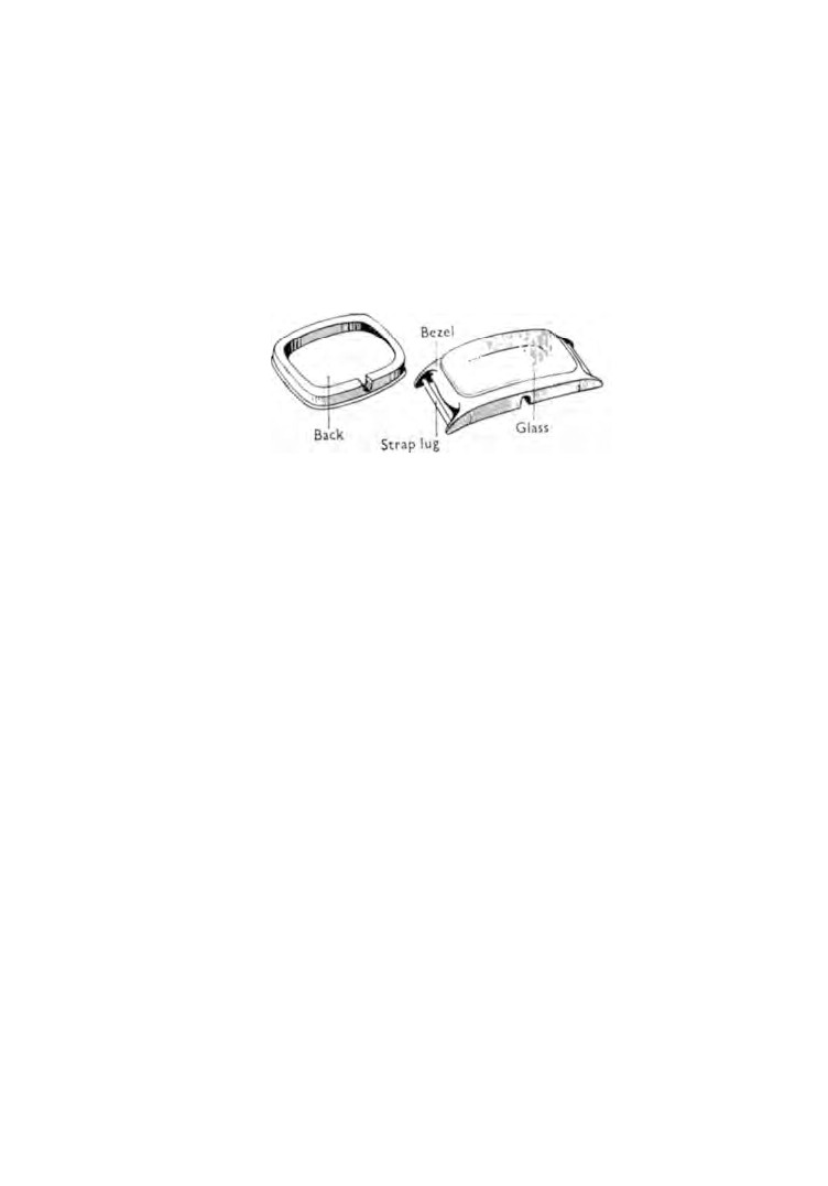
Wristwatch cases. Many are designed similar to pocket
watches but the modern trend is to fit movements into two-piece
cases as shown in figure 69. The bezel either fits over the back as
illustrated or snaps on. Because the two-piece case has only one
detachable part, the possibility of dirt and dust entering the case
is reduced. This type of case is becoming increasingly popular
among manufacturers.
The majority of American watch cases are fitted with screw-on
bezels and backs. This is undoubtedly the best method of main
taining internal cleanliness.
Fig. 68. Pocket watch case.
109
110
WATCH AND CLOCK REPAIRS
American manufacturers were the first to produce the gold-
filled watch case.
A sheet of brass is sandwiched between thin gold sheet and
all are brazed together. The metal is then rolled to the required
thickness, pressed out and polished. The result is a brass case
with a gold face inside and outside. These cases are very hard
wearing.
Fig. 69. Wristwatch case.
Opening a case. Before attempting to open a case it should be
examined to make sure that the method of assembly is under
stood. A screwed-on back will be indicated by slots or by a series
of flats cut in the edge to take a key or the edge may be knurled
to enable the back to be gripped in the hand and unscrewed by
hand pressure.
A screwed-on bezel will have a knurled edge.
Snaps can be identified by a shallow groove on the edge to
provide entry for a knife blade, or the edge may have a lip to act
as a lever.
If the snap has neither groove nor lip, a sharp knife blade is used
inserted in the join.
When opening a good fitting case, great care must be exercised.
The knife can slip and disfigure the finish. Damage can be caused
to the edge of the snap. The join can be bruised by the incorrect
use of the knife blade.
Most screw-on fittings can be removed without the use of
tools. Place the watch face down in the palm of the left hand.
Press down firmly with the other palm and at the same time turn
in a counter-clockwise direction.
CASES
111
To remove a snap by means of a knife blade, first ensure that
the blade is sharp. Next push the blade firmly and cleanly into
the join. Now lean the blade over so that the cutting edge presses
against the case middle allowing the blade face to push off the
snap. Never twist the blade when it is in the join ; the cutting edge
will damage both the snap and the case middle.
Removal of the movement from the case is dealt with in
Chapter
5.
Repairs. A bruise in the case middle can be pushed out from
the inside by using a suitably rounded implement such as a piece
of boxwood.
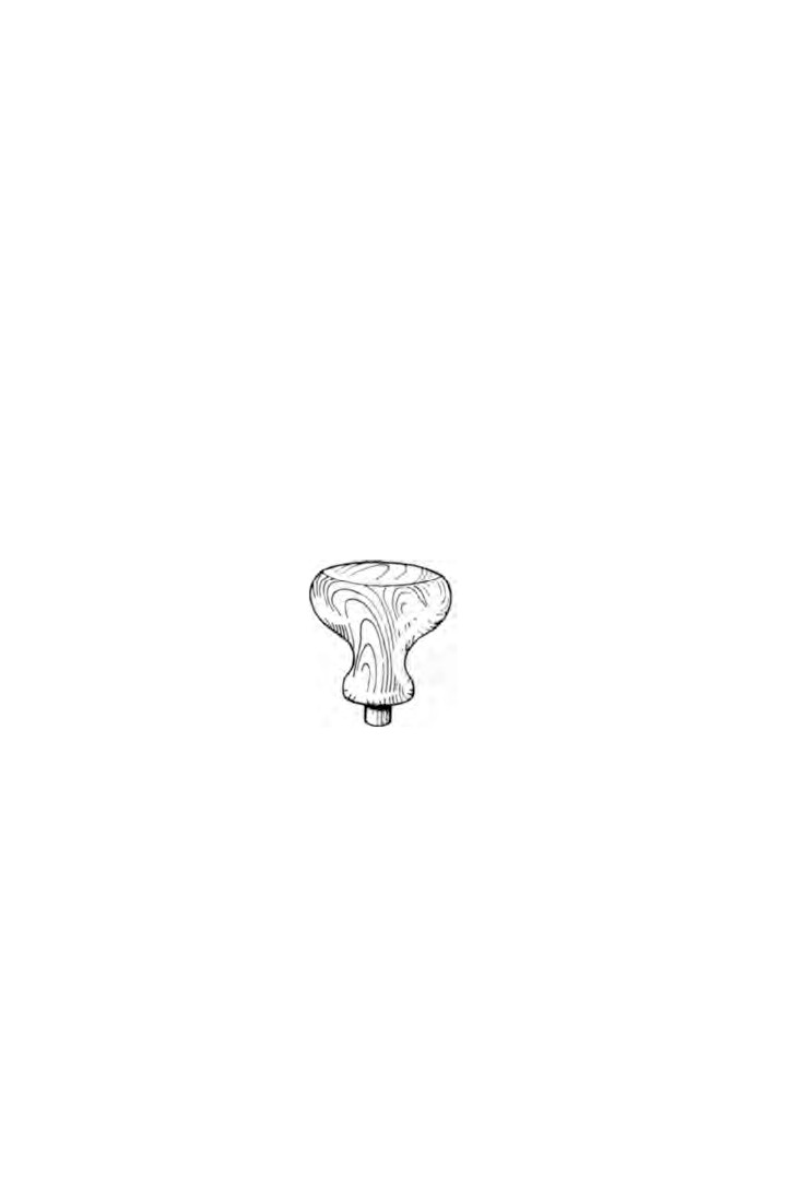
Bruises in domes and backs can be lightly tapped out with a
wooden mallet whilst the dome or back is supported on a box
wood stake
(Fig.
70). The stake should be covered with tissue
paper to prevent marking the work.
Small bruises in the glass groove of a bezel can be pushed out
Fig. 70. Boxwood stake.
by using a small screwdriver from the inside. Considerable care
must be exercised otherwise the glass will not fit correctly.
Side movement of hinges should be eliminated. In many cases
the renewal of a hinge pin will be all that is required.
The old pin is carefully driven out a distance sufficient to
enable the pliers to obtain a grip. The pin can then be pulled
completely out.
Select a piece of steel rod of the correct diameter and cut it
about 1/8 in. longer than is required, insert the pin so that an equal
112
WATCH AND CLOCK REPAIRS
length is protruding at each end. These ends are carefully filed to
blend with the shape of the case. File marks are removed by using
the smoothest grade of emery cloth and then polishing.
Worn snaps can be tightened by inward burnishing of the edge
with a wetted oval burnisher, or the snap on the case middle can
be burnished outward.
A snap that is too tight can be loosened by removing a little of
the metal all round the inner edge, finishing off with a burnisher.
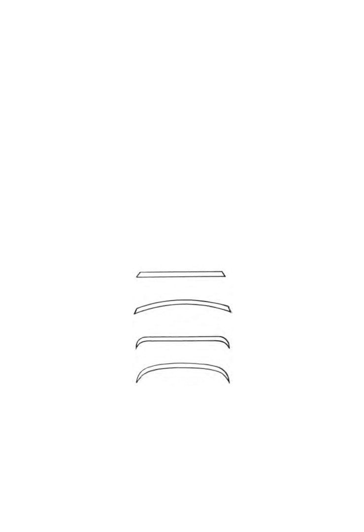
Glasses. Some of the more popular designs are shown in
figure
71. A loose glass can frequently be fixed in its bezel by
applying some glue to the glass groove with the point of a
pegwood stick. Place the glass in position, rotate it in the bezel
to spread the glue and put aside to dry.
The edge of the glass groove should never be burnished
inward to make a glass fit as this will damage the bezel.
Glasses are fitted by hand and to snap a good fitting glass into
its bezel requires practice. Glasses should never be fitted with the
bezel in position on the watch case.
a
b
c
d
Fig.
71. Glasses,
(a) Flat crystal,
(b) Crystal,
(c) Double lunette,
(d) Lunette.
CHAPTER FOURTEEN
Magnetism
IT is not uncommon for watches to suffer from magnetism. The
effect is erratic time-keeping, gaining at irregular intervals
similar to that which is brought about by oil on the hairspring.
Much of the repairer's time can be spent chasing a watch fault
whilst the real cause of magnetism remains undetected. Therefore,
before we leave the overhaul of watches a few words about
magnetism may save a few frustrating hours in the future.
For magnetism to have any noticeable effect on a watch it must
be present in the hairspring. Other steel parts such as the keyless
work, screws and mainspring are not likely to effect time
keeping if they themselves become magnetized.
In many modern watches the escapement is made from non
magnetic metals for this very reason. However, there are still
large numbers of watches made with steel hairsprings that can
be magnetized and it is with these movements that we are going
to be concerned.
Remove the back of the case and with a pointed pegwood stick
close the coils of the hairspring and see if they stick together
when the pegwood is removed.
Now place a pocket compass on the balance cock. The compass
needs to be the smallest obtainable for lightness and sensitivity of
the needle. A very suitable type is the toy that is sometimes found
in party novelties.
Position the compass centrally over the balance pivot. Set the
balance in motion and note the effect on the compass. The needle
may vibrate in harmony with the balance or it may make
complete revolutions, but in either case the presence of magnetism
has been established.
If the needle remains stationary, tap the compass in case the
needle has stuck.
Lift the compass from the watch and take the watch away. If
113
114
WATCH AND CLOCK REPAIRS
the needle then moves it indicates that some other part of the
watch is magnetized and was attracting and holding the compass
needle in one position.
To check this, replace the watch under the compass in the same
position as before and the compass needle should swing back.
Another check is to lift the compass just clear of the balance
cock, slowly rotate the watch and see if the compass needle
follows the movement of the watch.
To demagnetize a piece of steel the part concerned is placed in
the magnetic field set up around a coil of wire through which is
passed an electric current. The part is first fully magnetized and
then slowly withdrawn from the magnetic field.
The hairspring must be removed from the watch and wrapped
in tissue paper in order to preserve its shape during the demag
netizing process.
If this were not done and the complete watch was put in the
coil, or if the hairspring alone was put in the coil without protec
tion, then when the electric current was switched on and the
spring subjected to the full magnetic force the pull would far
exceed the spring tension and the coils would become entangled.
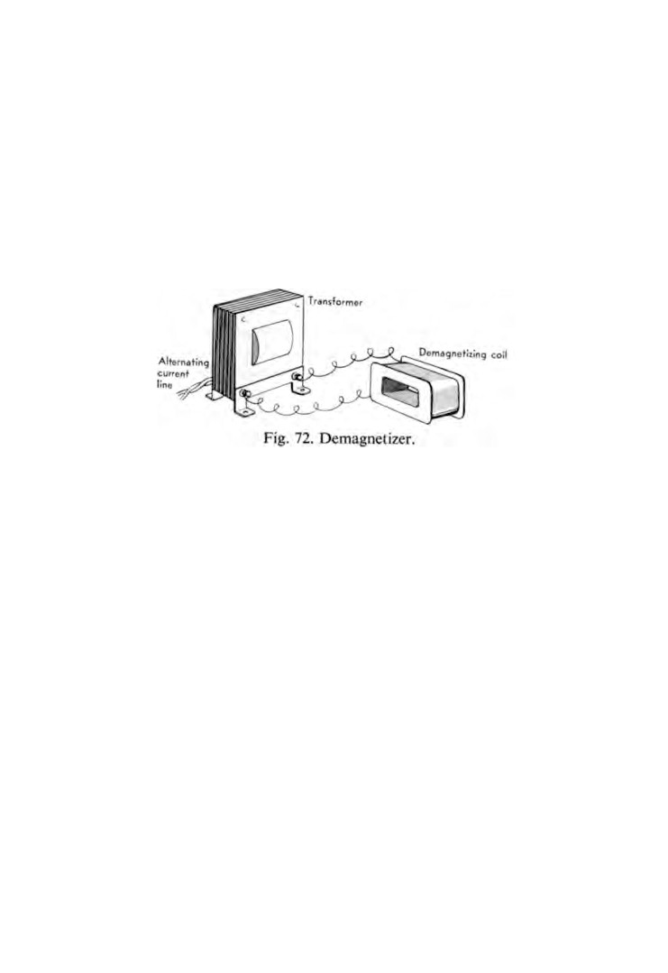
The demagnetizer (Fig.
72), consists of a tightly wound coil
on a hollow bobbin, the hole being large enough to accept
watch parts with plenty of free space.
The coil is connected to an A.C. current through a
transformer which provides the coil with a pressure of about
six volts.
MAGNETISM
115
The hairspring is placed in the centre of the coil and the current
is switched on. After a few seconds the hairspring is slowly
withdrawn to arm's length and then the current is switched off.
It frequently happens that the first treatment of demagnetizing
does not provide a complete cure. Therefore, when the hairspring
is refitted to the watch and a further test is made, do not discard
the possibility of magnetism still being present if the compass
needle gives an indication.
Part Three
CLOCKS
CHAPTER FIFTEEN
The movement
As a time-piece the basic principle of a clock movement is the
same as that of a watch. It has its motive power, train of wheels,
escapement, and motion work with dial and hands.
Motive power is supplied either by a wound spring or by
hanging weights.
From figure
24 we can see that the order of the wheels in a
watch is: the barrel, the centre wheel, the third wheel, the fourth
wheel and the escape wheel.
In a clock the barrel does not mesh with the centre wheel
pinion. The order is: the barrel, the intermediate wheel, the
centre wheel, the third wheel and the escape wheel.
The three most common types of clock escapements are the
pin-pallet, the cylinder and the recoil. The pin-pallet is used
mostly in the lower priced alarm clocks and watches and has
been dealt with fully in Chapter
10.
The cylinder escapement is fitted to carriage clocks and is
described in Chapter 20.
Whereas these two escapements are fitted with balance wheels,
the recoil escapement, which is described in Chapter
16, is
controlled by a pendulum.
When mechanisms such as strike and chime are added they
tend to make the complete movement complicated. It is therefore
better to make a study of these mechanisms separately. Part
3
has been written with this in mind.
116
THE MOVEMENT
117
The procedure for cleaning varies with some movements and
in those cases it has been included in the chapter concerned,
otherwise cleaning is the same as described in Chapter
16.
The technique of oiling has been fully described in Chapter
5
and applies equally well for clocks.
The dials of some movements are screwed to the front of the
case. In others, the case itself is the dial.
Winding a pendulum movement is almost always done by
inserting the key at the front. This is to avoid disturbing the
clock and upsetting the balance. With other types of movement,
where this precaution is unnecessary, winding is done at the back.
There are many methods of securing movements to cases, but
whatever the method it will be obvious after inspection.
The remaining chapters in this section are devoted to different
types of clock movements, it seems fitting therefore that in this
chapter some mention should be made of clock cases.
Quite often a great deal of work is put into the overhaul of a
movement which is then replaced in a case that contains enough
dirt to stop the clock on sight.
Apart from the important task of cleaning the case interior, a
few moments spent on the exterior often makes a big difference
to its appearance.
Materials used for the manufacture of clock cases include wood,
metal, stone, plastic and glass.
If the case is dirty give it a good cleaning. If it needs repairing,
assuming the damage is not extensive, then a few minutes spent
on a minor repair are worth while.
Clean the interior of the case. It is surprising how much dirt
and dust can collect.
If the case is made of wood, examine ornamental pieces on the
outside for security. Do the same with any strengthening blocks
inside. Loose pieces can be glued into position.
Dust in carvings or scrolls can be removed by using a soft
brush. Furniture cream will improve the appearance of polished
wood.
Inspect bezel hinges and door hinges for security and condition.
118
WATCH AND CLOCK REPAIRS
Renew the screws if necessary. If the screws continue to turn when
being tightened remove them and plug the holes with pieces of
match-stick and replace the screws.
Other cases can be wiped with a clean soft cloth moistened in
warm soapy water. Finish off with a soft dry rag.
Make sure the dials are clean. Lightly brush them with a
watchmaker's soft cleaning brush. Enamel dials can be wiped
with benzine.
Clean and polish the glass. Do nothing with lacquered brass-
work other than rub it lightly with a soft cloth. Tarnished brass
is best left alone.
CHAPTER SIXTEEN
Pendulum clocks
IN this chapter we are going to overhaul a simple pendulum clock
of the lower priced domestic variety. It seems reasonable to say
that these clocks are one of the most popular clocks in the home
today.
Their low price is brought about by the high rate of mass
production. Large quantities are manufactured in Germany,
the United States and Great Britain.
The movements themselves are readily recognized. The plates
and wheels are coated with lacquer and many of the parts are
pressed out by machine. Providing they are kept clean, oiled and
adjusted these clocks give excellent service over long periods.
In Chapter 15 we spoke about taking movements from their cases
and removing dials and hands. Let us assume that this has been
done and that we are now ready to proceed with the overhaul.
First of all we need a small but strong cardboard box on which
to place the movement and so prevent the many protrusions from
damage. Better still of course would be a home-made box of ply
wood cut to fit the movement.
Now let the mainspring down. If the movement is very old the
chances are that the mainspring will not be contained in a barrel
in which case a mainspring clamp will have to be fitted.
Place the key on the winding square and turn it in the direction
of winding. This will throw the ratchet click out which must then
be held in this position. Allow the tension of the spring to turn
the key backwards until your hand can go no farther. Release
the ratchet click back into the ratchet and then you may let go
of the key. Repeat this process until the spring is completely
unwound.
These springs are very powerful and could cause personal
injury to hand or fingers if allowed to run down out of control.
Apart from this, to do such a thing would most probably result
119
120
WATCH AND CLOCK REPAIRS
in a broken spring. So take care and make sure that the movement
is held firmly, that the key will not slip in your hand and that the
click can be released immediately and at any time.
Remove the minute wheel collet, lift off the hour wheel and
then remove the minute wheel.
Worn pivots and pivot holes have an effect on the depth of
mesh between the wheels and their pinions and the locking of the
escapement. Hold each arbor between the finger and thumb, or
stout tweezers if the arbor is not accessible, as near the pivot as
possible and check the amount of side-shake. Make a note of
any holes that are considered to be in need of bushing. The best
way of assessing whether or not the side-shake is excessive is to
compare it with a movement of similar size that has had little or
no wear.
Once having experienced the amount of side-shake in a new
clock, subsequent inspections will prove less difficult.
Examine each arbor to make sure it has end-shake. There must
be sufficient clearance to prevent the shoulders of the pivots
binding against the plates.
Providing there is no excessive side-shake in the pallet arbor
pivot holes and the escape wheel arbor pivot holes we can go on
to check the recoil escapement, otherwise checking the escape
ment must wait until the worn pivot holes have been bushed.
Wind up the mainspring a few clicks, hold the movement in
the left hand and operate the crutch with the right hand. Examine
the faces of the pallets for wear. Observe through an eye-glass
the action of the escape wheel teeth dropping on to the pallets and
at the same time form an idea of the angle of swing the pendulum
must make to release the escape wheel teeth.
It will be seen that deep locking will necessitate the pendulum
passing through a large angle of swing which in turn demands
more power. Remember also that if the pallet fails to release an
escape wheel tooth just once, the clock will stop.
If on the other hand the depth of locking is too shallow mis-
locking is likely to occur.
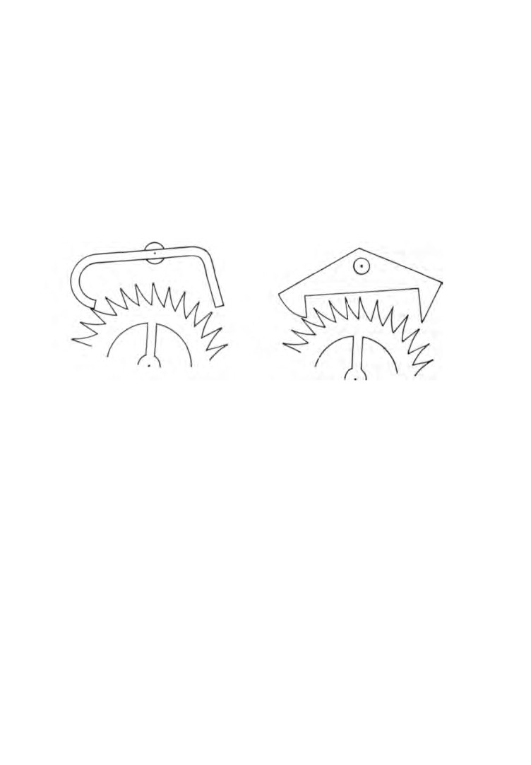
There are two types of pallets used, the strip pallet (Fig. 73, left),
PENDULUM CLOCKS
121
and the solid pallet fitted to the Garrard escapement (Fig. 73, right),
both of which are provided with means of adjusting the depth.
In the case of the movement fitted with a strip pallet, the screw
holes in the pallet cock are elongated and all that has to be done
is slacken off the two screws, reposition the pallet cock and tighten
the screws. It is a matter of trial and error but the correct position
is quickly found.
Adjusting the depth of a solid pallet is done by altering the
position of a screw on top of the back plate. Slacken off the two
Fig.
73. Recoil escapements. Strip pallet {left) and solid pallet (right).
pallet cock screws, rotate the adjusting screw and tighten the
pallet cock screws. By turning the adjusting screw in a clockwise
direction the pallet cock is raised which reduces the pallet depth,
and of course, to increase the depth the screw must be turned
counter-clockwise.
Having checked and adjusted the pallet depth we have ensured
that the escape wheel teeth will be properly locked. Now we can
examine the amount of drop.
The drop of an escape wheel is the distance it travels from the
release of a tooth from one pallet to the next arrest of a tooth
by the other pallet.
To check the drop apply the same technique as was used when
checking the pallet depth. In determining whether the amount of
drop is correct, again the best advice is to compare it with a
similar clock that has had little wear. Make a note of the adjust-
122
WATCH AND CLOCK REPAIRS
merits that are needed then remove the pallet cock and lift the
pallet arbor from the movement.
If the pallet is the strip type all that is needed is to bend the
offending pallet or pallets. Bending the entry pallet outward will
decrease the drop on that pallet, and bending the exit pallet
outward will increase the drop on that pallet.
These strip pallets are quite soft and can be bent cold but as a
precaution against cracking it is advisable to heat them first.
Now that the pallet is out of the movement this is a good
opportunity to deal with worn pallet faces. Use a dead-smooth
file to restore the faces to their original surface, smooth off with
the finest emery stick and finish with a burnisher.
With the solid type of pallet the drop can be increased by
reducing the entry faces. These pallets are too hard to file and a
stone must therefore be used. An oilstone such as is used by a
cabinet maker is best for this job. Make sure the stone is kept flat
and that it follows the contour of the pallet.
The marks from the oilstone are then removed by an oilstone
slip keeping the grain flowing with the pallet. Finish off with a
very fine emery stick and then burnish.
Little can be done to decrease the drop in the solid type of
pallet but this is not important. What is important is to avoid
having too little drop. Such a condition can, after pivot holes are
worn, lead to the pallets fouling the tops of the escape wheel
teeth and stopping the clock.
One last word about checking the drop of the escape wheel.
All escape wheel teeth must be checked with both entry and
exit pallets. Any variation in drop on one side of the wheel to a
position diametrically opposite will indicate the wheel being out
of round.
With the pallet arbor out of the movement we are now ready
to check the depth of mesh between the wheels and their
pinions.
Gearing is a subject about which complete books have been
written. It matters little whether we are interested in horology
or civil engineering, the theory of gearing is the same. Correct
PENDULUM CLOCKS
123
depth of mesh, one of the many aspects of gearing, plays a very
important part.
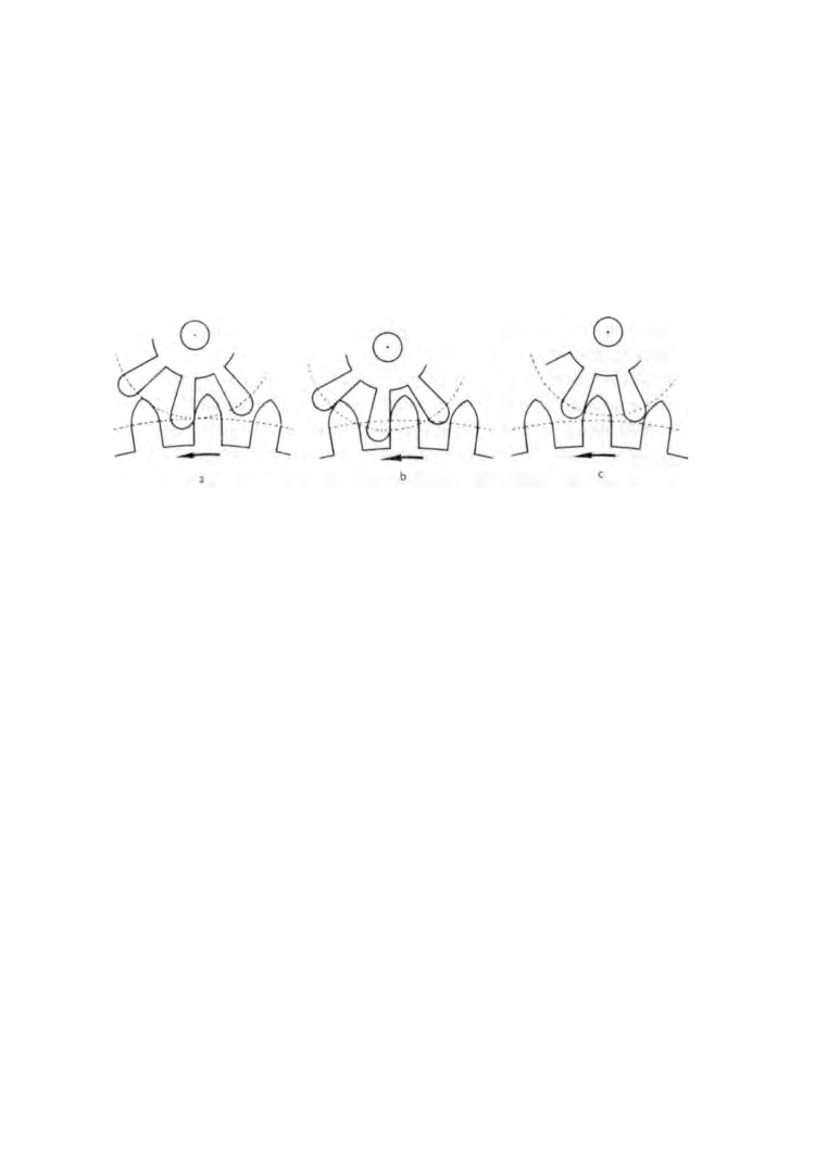
Figure 74, a, shows a wheel and pinion in correct mesh, b the
mesh is too deep, and c it is not deep enough.
Our main concern is to ensure that the wheels and pinions in
the clock movement do not suffer from too much depth of mesh
causing harshness in operation. This can be checked by the sense
Fig.
74. Gear wheel and pinion in mesh, (a) Correct, (b) Too deep,
(c) Too shallow.
of touch and is not as difficult as it may seem. After a little prac
tice you will soon be able to detect those gears whose mesh is
causing trouble.
We will commence with the third wheel and the escape wheel
pinion. Hold the escape wheel by the tip of the first finger of the
left hand and with the other hand rock the third wheel backward
and forward. Although the movement is small any stiffness
present can be felt.
Now press down lightly on the escape wheel arbor and slowly
rotate the third wheel. Apart from your finger pressure causing
slight resistance the action should be smooth and free from any
roughness.
If tightness is experienced in one position but not in another
the possible causes are :
(a) damaged teeth
(b) bent arbor
(c) wheel out of round
124
WATCH AND CLOCK REPAIRS
If the teeth are broken or damaged beyond repair, new teeth
can be fitted as explained in Chapter 6. If a tooth is bent towards
an adjoining tooth it can be straightened by inserting the blade of
a pocket knife between the two teeth and levering the bent tooth
back into position. If the tooth is bruised it can be shaped with a
thin smooth file and finished with a very smooth emery stick.
A bent arbor can be straightened cold. Find out first of all
where the bend is by spinning the arbor and then place it on a
flat steel stake and tap it straight with the peening end of a
watchmaker's hammer.
If a wheel is out of round it can only be put right by renewing
the wheel or by recutting the teeth with a topping tool.
The equipment for topping wheels is unlikely to be in the
possession of a beginner, therefore this job will have to be sent
away to be done. The same comments apply to bushing worn
pivot holes. In both cases the repairer will require the front and
back plates, pillar nuts and the wheels and pinions that are
causing trouble.
To continue with the dismantling. Remove the pillar nuts and
carefully lift off the back plate. Take out the escape wheel,
third wheel, intermediate wheel and barrel. Hold the front plate
in the palm of the left hand with the cannon pinion uppermost.
Strike the centre arbor a sharp blow with a brass-faced hammer,
this will free the cannon pinion allowing the centre wheel to be
lifted out.
Now the barrel needs inspecting. Hold the square end of the
barrel arbor between the jaws of the brass-faced pliers and try
the end-shake. If there is none, place the barrel over a piece of
tubing and gently tap the arbor and try the end-shake again.
Repeat this until the end-shake is just perceptible.
It matters little which end of the arbor is tapped by the hammer
but remember that the end-shake has an influence over the
position of the barrel in the movement. Consideration should
be given therefore to other parts in the immediate vicinity of the
barrel in deciding which end of the arbor to hit.
Next, remove the barrel cover. This is done by levering it off
PENDULUM CLOCKS
125
with a screwdriver. Make sure it is marked before you take it off
so that there is no difficulty in putting it back into its correct
position.
Examine the condition of the spring. If it is clean and oiled
with no signs of corrosion don't disturb it. If the spring is broken,
or if it has to be removed for any other reason, then first remove
the arbor. To do this it will be necessary to turn it back a little
to unhook it from the eye of the spring.
Pull out the centre of the spring very carefully using the brass-
faced pliers. As soon as enough spring to hold has been pulled
out, the rest of the spring is allowed to uncoil itself from the
barrel. This operation must be done slowly and carefully.
If the spring were allowed to fly out, it is doubtful whether it
could be used again due to distortion.
This completes the dismantling of the movement.
It is a recognized fact that when two dissimilar metals move
against each other, such as a steel pivot revolving in a brass plate,
the harder of the two metals will show signs of wear first. This
is because fine particles of dust embed themselves in the soft
metal which then becomes an abrasive and cuts the hard metal.
It follows then that if pivot holes need bushing the pivots
themselves will most certainly need polishing, and further to
this, bushing cannot be carried out until the pivots have been
polished because the bushes have to be drilled to suit the pivots.
When the work of bushing the plates is sent away the repairer
will polish the pivots at the same time.
Having carried out all necessary repairs we are now ready to
proceed with the cleaning. We will need a tin measuring about
6 in. x 4 in. and about 1 1/2 in. deep to hold the cleaning fluid.
A 1/2-in. paint brush makes a good brush for washing the parts.
We will also require a tapered strip of chamois leather, a piece
of soft linen, some pith sticks, some pegwood and a folded
newspaper.
Hold the parts over the cleaning fluid and well brush them with
the wet brush, continually dipping the brush into the fluid. Make
sure all the wheel teeth and pinion leaves are well brushed. Treat
126
WATCH AND CLOCK REPAIRS
all the parts alike, both brass and steel, and lay them on the
folded newspaper to drain. Use the linen cloth to dry them and
to polish the arbors. Lightly brush the parts with a medium watch
brush charged with chalk.
Shave a point on the end of a pegwood stick and peg out the
bearing holes. Larger holes can be cleaned out by the strip of
chamois leather. Clamp the wide end to the bench, thread the
narrow end through the hole and run the plate up and down the
strip.
Push the pith stick well on to each pivot and twist it round a
few times.
If the mainspring has been washed, dry it with the piece of
linen.
Finish off by brushing all the parts with a clean soft watch
brush.
Now wind the mainspring into the barrel. Start off by hooking
the outer end to the barrel wall and then slowly feed the spring in
and at the same time rotate the barrel. When the spring is in do
not attempt to push it down because of the possibility of
causing damage. Tap the barrel on the bench two or three times,
this will cause the spring to settle down to its correct position.
Now put the arbor in making sure that the eye of the spring is
properly hooked and wrapped around the arbor.
Oil the edges of the mainspring and snap the cover on. Oil the
arbor bearing hole in the cover and in the barrel. The movement
is now ready for assembly.
Lay the front plate over the cardboard box and place the
barrel and the wheels in position. Lower the back plate on to the
movement and with a pair of tweezers manipulate the pivots into
their respective holes
When all the pivots are in, the back plate should be resting on
the pillars. The pillar nuts can then be put on finger tight.
Make sure that all the arbors have end-shake and then tighten
down the back plate. Oil all the pivots in both plates.
Wind up the mainspring two or three clicks and check the
wheel train for freedom.
PENDULUM CLOCKS
127
Now fit the cannon pinion. Place the movement on a block of
hard wood front plate uppermost. Push the cannon pinion on to
the centre arbor and drive it home using a hollow punch and a
hammer. Check the centre arbor to make sure it has end-shake.
Again wind up the mainspring a few clicks to make certain
everything is free.
Refit the motion work, the pallets and the pallet cock. Apply
a spot of oil to each pallet and oil the pallet arbor pivots.
The movement is now ready to be fitted into its case. When this
has been done, hang the pendulum and the movement should
function.
Refit the hands making sure that when the hour hand points at
one of the numerals the minute hand is immediately over the
12.
CHAPTER SEVENTEEN
Striking clocks
THE striking mechanism of a clock can best be understood if it is
divided into two groups, the motive power and the release
mechanism.
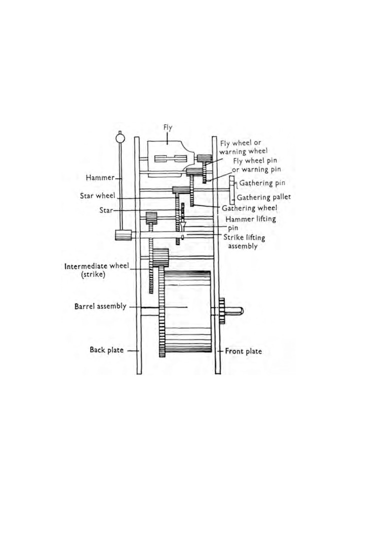
A typical striking clock is shown in Plate VII. The striking
mechanism has been illustrated diagrammatically in figures
75
and 76.
It will be seen that when the strike mainspring is wound up,
energy is transmitted to the fly wheel. On the face of the fly wheel
is a pin. The upper end of the hour locking lever is bent so as to
arrest the pin and prevent movement of the wheel train.
The cannon pinion cam lifts the hour warning lever which in
turn raises the hour locking lever. As the hour locking lever
rises :
(a) the fly wheel pin is released, the fly wheel rotates half of a
turn and is again arrested by the hour warning lever.
This movement of the fly wheel is known as the 'warning'.
(b) The hour locking lever releases the gathering pallet which
rotates a short distance during the half turn of the fly wheel.
The hour warning lever continues to rise and releases the fly
wheel, the wheel train goes into operation and at the same time
the rack falls on to the snail. The edge of the snail is shaped into
twelve different steps, one for each hour. Whilst the wheels are
turning the star hits against the hammer lifting pin causing the
hammers to operate.
The gathering pallet revolves and the gathering pin engages the
rack teeth lifting the rack one tooth at a time.
During the period when the pin is moving round to engage
another tooth the rack is held by the hour locking lever engaging
with the teeth.
128
STRIKING CLOCKS
129
Finally the rack is gathered up which allows the hour locking
lever to fall and engage in the slot of the gathering pallet and
at the same time to arrest the fly wheel from further movement.
Now to proceed with the overhaul. Let both mainsprings down.
Remove the hammers, the back cock and the pallets.
Fig. 75. Strike wheel train.
Unpin and remove the rack, the hour and minute wheels, the
hour warning lever and the hour locking lever.
Inspect all pivot holes for wear and note those that require
bushing. Place the movement, back plate uppermost, over a
suitable box and unscrew and remove the back plate. Lift out the
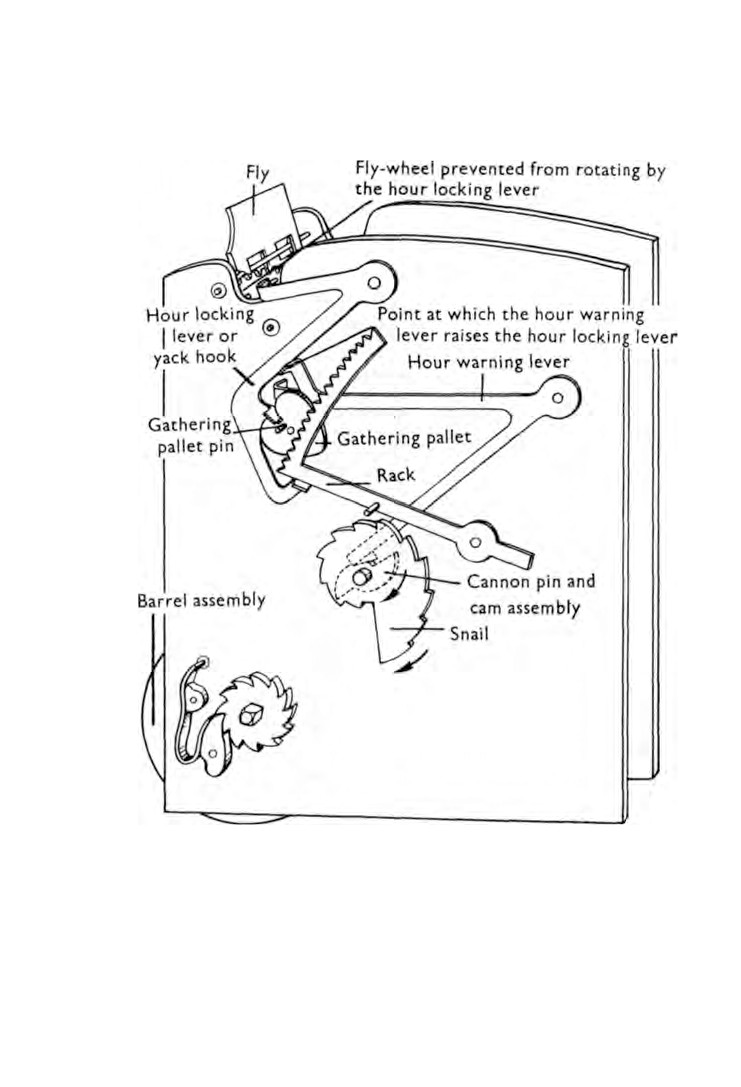
Fig. 76. Strike release mechanism.
STRIKING CLOCKS
131
barrels and mark one of them to ensure that they are refitted in
their original positions, then lift out the wheels.
Remove the cannon pinion as described in Chapter
16 and
treat the gathering pallet in the same way.
Carry out any necessary repairs and lay the parts out for
cleaning. If the parts are lacquered it is sufficient to wash them
and lightly chalk-brush them. Clean out the pivot holes.
We can now go ahead and assemble and oil the movement in
the usual way and therefore we must consider the strike mechan
ism once again.
When all the parts have been positioned on the front plate and
the back plate has been properly located, screw on two nuts
finger tight diagonally opposite each other.
Turn the wheel train in the normal direction of rotation until
the warning pin on the fly wheel is pressing against the hour
locking lever. In this position the hammer lifting pin should be
midway between two teeth of the star. If it is not, the back plate
must be lifted and the star wheel disengaged and moved round.
Replace the back plate and check again. When these two wheels
have been correctly positioned the back plate can be fully
tightened down with all four nuts.
With the hour locking lever in the downward position and
arresting the movement of the fly wheel, the gathering pallet is
fitted to its pivot so that the bent arm of the hour locking lever
is engaged in the notch of the gathering pallet.
Operate the strike mechanism and note the position on the
snail where the rack falls. If it does not drop on to the beginning
of a step then the hour wheel will have to be moved round.
Complete the assembly of the movement and fit the dial. Turn
the minute hand round until the strike operates. Fit the minute
hand so that it points to
12 and the hour hand to point to the
hour that had been struck.