Boeing 737 - 600/700/800/900. Operations Manual (1997 year) - page 25
Airplane General, Emergency
Equipment, Doors, Windows -
Systems Description
Boeing 737 Operations Manual
Doors and Windows
The airplane has two passenger entry doors, one cabin door
(the flight
deck/passenger cabin entry), two service doors and two cargo doors. There is also
a center electrical and electronic (E/E) equipment access door and an equipment
compartment access door on the bottom of the airplane.
The flight deck number two windows, one on the left and one on the right, can be
opened by the flight crew.
Cabin Door
[Original Flight Deck Door]
An electrical and keyed lock permits the door to be opened, closed and locked
from either side. With 28 Volt DC power available, the door may be electrically
locked or unlocked by pressing the door lock switch on the control stand; entrance
from the passenger cabin requires a key when the door is electrically locked. The
door cannot be locked without electrical power.
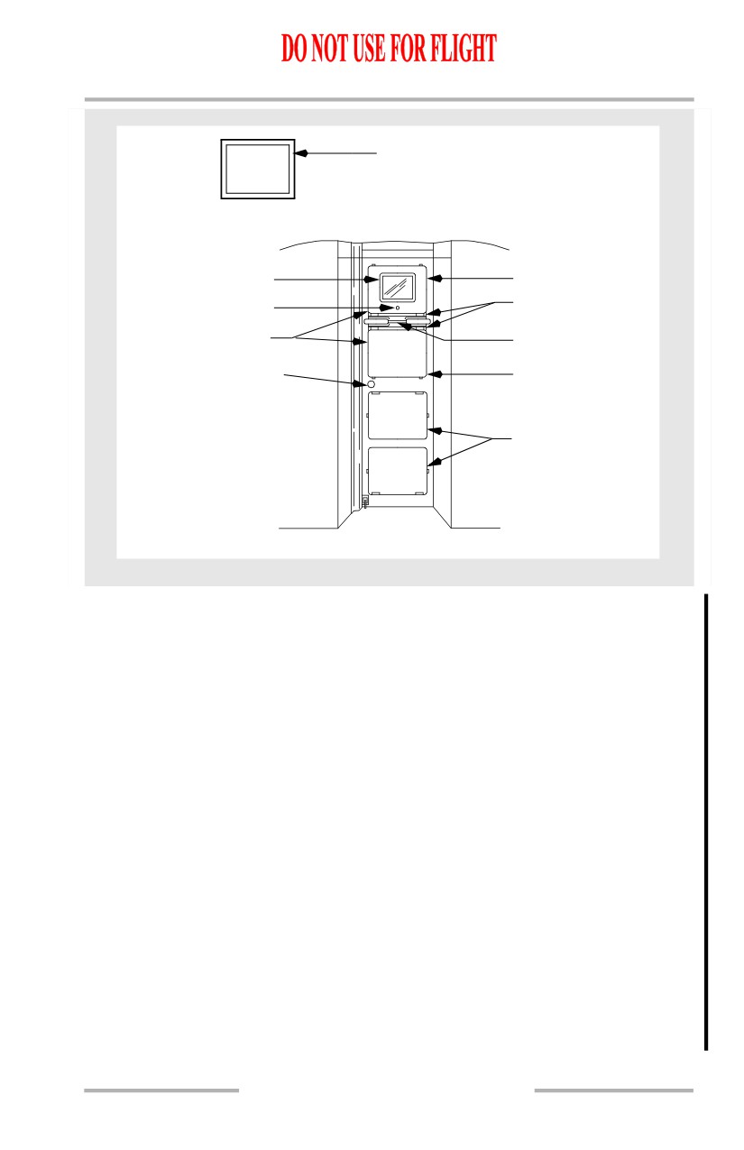
There are four blowout panels located in the cabin door. In the event of a sudden
depressurization of the flight deck, the blowout panels hinge out from the door.
This uncovers openings in the door and allows the air pressure in the flight deck
and passenger cabin to equalize.
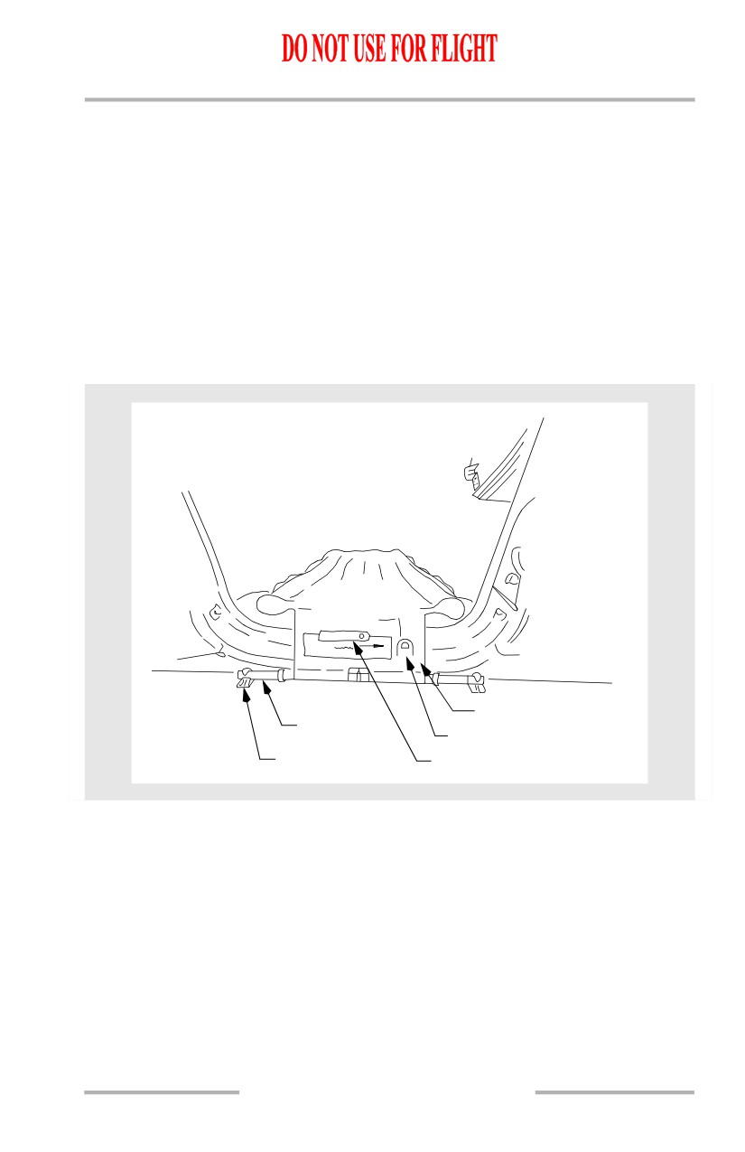
An emergency exit feature is also provided which permits the release and removal
of the two upper blowout panels from the door. To operate, pull on the release
handle while pressing on the panel below the release handle. Panel will not release
unless both ends of handle have been pulled away from their locked position.
1.40.22
Airplane General, Emergency
Equipment, Doors, Windows -
Systems Description
Boeing 737 Operations Manual
DOOR LOCK SWITCH
CAB DOOR
UNLOCKED
- Illuminates when the cabin
door is unlocked.
- Press to lock the door
AFT ELECTRONICS PANEL
when DC power is available.
MIRROR
BLOWOUT PANEL
PANEL HINGE
VIEWER
EMERGENCY EXIT
EMERGENCY
DOOR PANELS
EXIT HANDLE
DOOR HANDLE AND
BLOWOUT PANEL
ELECTRIC LOCK
BLOWOUT PANELS
FROM INSIDE FLIGHT DECK
Flight Deck Security Door
New Flight Deck Security Door]
The flight deck security door meets requirements for resistance to ballistic
penetration and intruder entrance. The door opens into the flight deck. When
closed, the door locks when electrical power is available and unlocks when
electrical power is removed. A viewing lens in the door allows observation of the
passenger cabin. The door can be manually opened from the flight deck by turning
the door handle. The door incorporates a deadbolt with a key lock on the passenger
cabin side.
The flight deck access system consists of an emergency access panel, chime
module, three position Door Lock selector, two indicator lights, and an Access
System switch. The emergency access panel includes a six button keypad for
entering the numeric emergency access code along with red, amber, and green
lights. The red light illuminates to indicate the door is locked. When the correct
emergency access code is entered, the amber light illuminates. The green light
illuminates to indicate the door is unlocked.
Two indicator lights and a three position Door Lock selector are located on the
aisle stand. Illumination of the amber LOCK FAIL light indicates the door lock
has failed or the Access System switch is in the OFF position.
1.40.23
Airplane General, Emergency
Equipment, Doors, Windows -
Systems Description
Boeing 737 Operations Manual
The emergency access code is used to gain access to the flight deck in case of pilot
incapacitation. A flight deck chime and illumination of the amber AUTO UNLK
light indicates the correct emergency access code has been entered and the door is
programmed to unlock after a time delay. Selecting the DENY position on the
Door Lock selector denies entry and prevents further keypad entry for several
minutes. To allow entry, the selector is turned to the UNLKD position which
unlocks the door while held in that position. If the emergency access code is
entered and the pilot takes no action, the door unlocks after expiration of the time
delay. Before the door unlocks, the chime sounds continuously and the AUTO
UNLK light flashes.
By pressing "1" then "ENT" keys on the emergency access panel, the flight deck
chime will sound (if programmed).
The door incorporates two pressure sensors that unlock the decompression panels
in the event pressurization is lost. The decompression panels have manual release
pins. Pulling the pins frees the panels allowing egress in the event the door is
jammed.
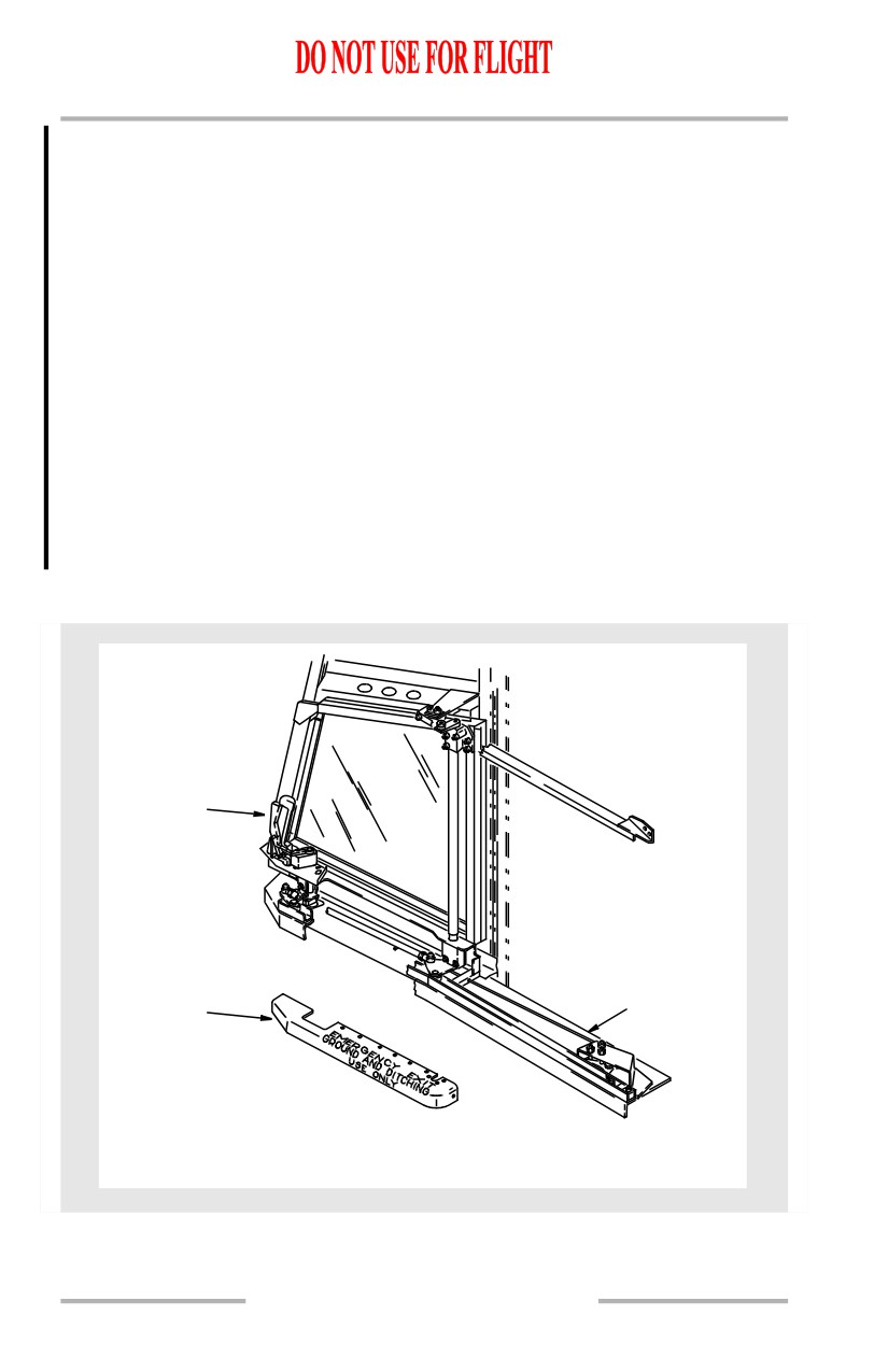
Flight Deck Number Two Windows
HANDLE WITH
TRIGGER
CLOTHES
GUARD
LATCH
PROTECTOR
MECHANISM
ROD
FLIGHT COMPARTMENT WINDOW NO. 2
(RIGHT SIDE SHOWN)
1.40.24
Airplane General, Emergency
Equipment, Doors, Windows -
Systems Description
Boeing 737 Operations Manual
The flight deck number two windows can be opened on the ground or in flight and
can be used for emergency evacuation. To open the window, depress the trigger
and turn the handle back and inboard. After the window moves inboard, move it
back until it locks in the open position.
To close the window, it must first be unlocked. Pull forward on the latch
mechanism rod to unlock the window. Depress the trigger and move the window
forward until the handle can be turned forward and outboard. When the trigger is
released, the window latches.
Only the first officer’s window number two window can be opened from outside
the airplane.
Lower Cargo Compartments
The lower cargo compartments are designed and constructed to satisfy FAA
category Class C compartment requirements. This means the compartments are
designed to completely confine a fire without endangering the safety of the
airplane or its occupants. The compartments are sealed and pressurized but do not
have fresh air circulation and temperature control as do the upper passenger
compartments.
There are two cargo compartment doors on the lower right side of the fuselage.
Both are plug type, inward opening pressure doors, hinged at their upper edges
and operated manually from either inside or outside the airplane. Except for slight
difference in shape, both doors are similar in design and operation. The door is
locked closed by four latches. Each door has a balance mechanism which creates
door-open force slightly more than equal to the weight of the door. The door can
therefore, with little effort, be swung open, until it engages a mechanical lock. The
door can be closed easily by pulling a lanyard attached to the door, releasing the
uplatch, grasping the handle and closing the door.
A pressure equalization valve is in the aft bulkhead of each compartment. The
valves let only enough air flow into or out of the cargo compartments to keep the
pressures nearly the same as the cabin pressure.
Blowout panels in the lower cargo compartments provide pressure relief at a
greater rate than the pressure equalization valve in case the airplane pressurization
is lost.
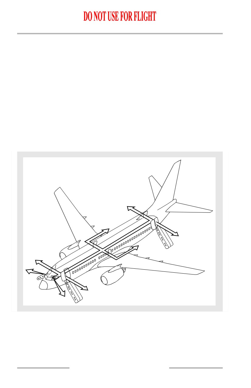
Emergency Escape
Emergency escape information included in this chapter includes:
• emergency evacuation routes
• flight deck windows
• escape slides
1.40.25
Airplane General, Emergency
Equipment, Doors, Windows -
Systems Description
Boeing 737 Operations Manual
• escape straps
• emergency exit doors
Emergency Evacuation Routes
[Option - 737-600/700]
Emergency evacuation may be accomplished through four entry/service doors and
two overwing escape hatches. Flight deck crew members may evacuate the
airplane through two sliding flight deck windows.
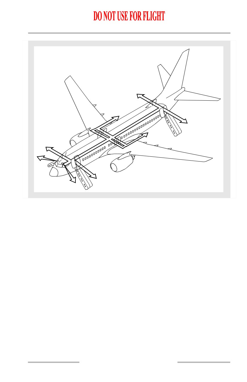
[Option - 737-800/900]
Emergency evacuation may be accomplished through four entry/service doors and
four overwing escape hatches. Flight deck crew members may evacuate the
airplane through two sliding flight deck windows.
Emergency Evacuation Routes
[Option - 737-600/700]
1.40.26
Airplane General, Emergency
Equipment, Doors, Windows -
Systems Description
Boeing 737 Operations Manual
[Option - 737-800/900]
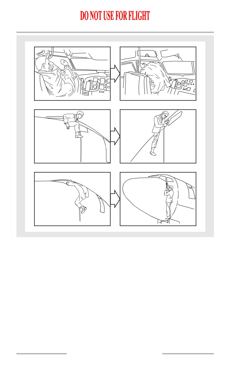
Flight Deck Window Emergency Egress
If the flight deck number two windows must be used for emergency egress, use
the following procedure:
• open the window
• open the escape strap compartment (above and aft of window)
• pull on the escape strap to ensure it is securely attached
• throw the strap out the window
• sit on the window sill with upper body outside
• exit in accordance with the following illustration.
CAUTION: Ensure the escape strap is securely fastened to the airplane.
1.40.27
Airplane General, Emergency
Equipment, Doors, Windows -
Systems Description
Boeing 737 Operations Manual
The above illustrated method of departure would probably be the easiest for most
crewmembers. This technique is difficult and should be used only in extreme
emergency.
1.40.28
Airplane General, Emergency
Equipment, Doors, Windows -
Systems Description
Boeing 737 Operations Manual
Escape Slide Detachment Handle
The slide has not been certified to be part of the water landing emergency
equipment. In a water environment, the slide may not properly inflate when
deployed. If the deployed slide is recognized to be a potential obstruction to
egress, a detachment handle is provided near the top of the slide. This handle is
protected by a cover and is placarded. The escape slide is detached from the
airplane by pulling the detachment handle. Once detached from the door sill, the
slide is tethered to the door sill by a lanyard. A properly inflated slide could be
buoyant, and useful as a flotation device for passengers in the water. Hand grips
are positioned along the sides of the slide.
Escape Slide Detachment Handle
TO RELEASE SLIDE
FOR DITCHING ONLY
1. LIFT FLAP
2. PULL HANDLE
PULL
PULL
PULL
GIRT
GIRT BAR
MANUAL INFLATION HANDLE
FLOOR BRACKETS
DETACHMENT HANDLE
1.40.29
Airplane General, Emergency
Equipment, Doors, Windows -
Systems Description
Boeing 737 Operations Manual
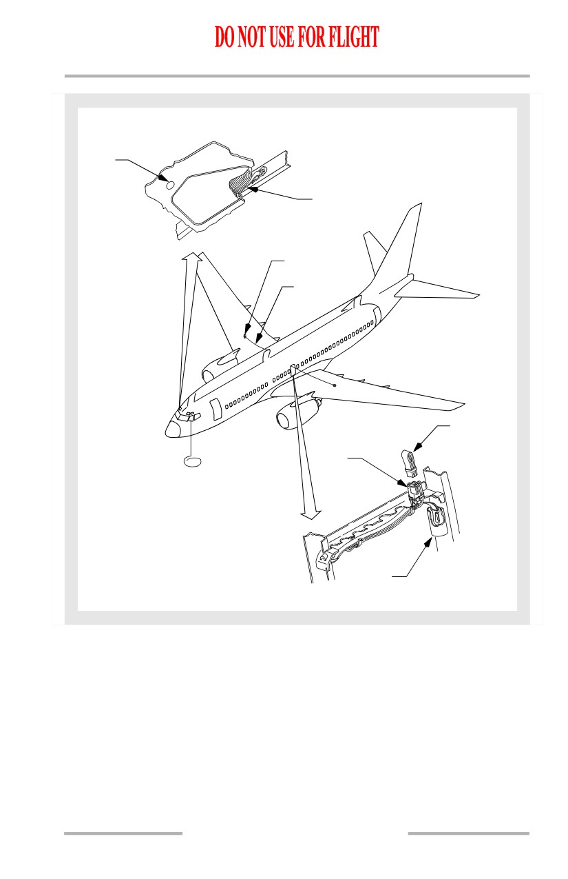
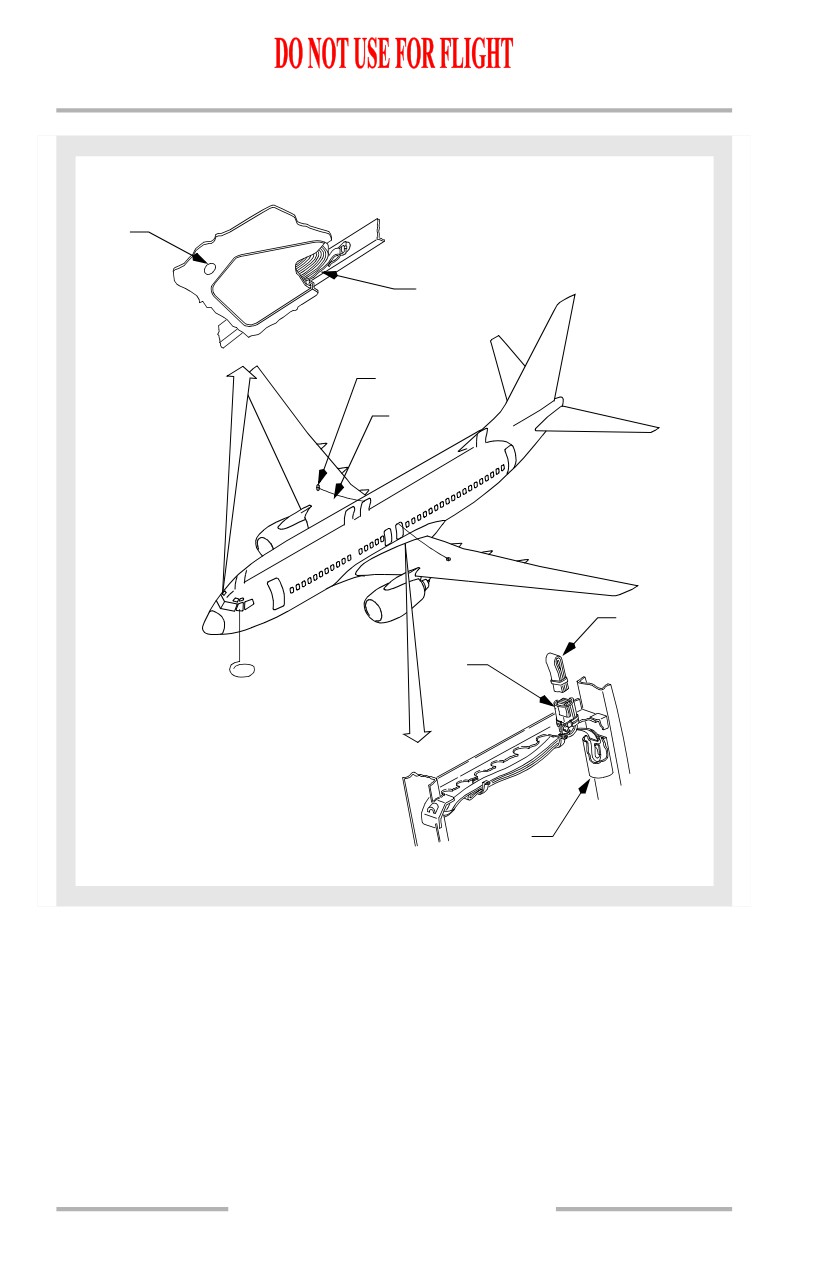
Escape Straps
[Option - 737-600/700]
Escape straps are installed above each emergency exit door frame. The escape
doors must be opened to expose the straps. One end of the strap is attached to the
door frame. The remainder of the strap is stowed in a tube extending into the cabin
ceiling. To use, the strap is pulled free from its stowage and attached to a ring on
the top surface of the wing. The escape strap can be used as a hand hold in a
ditching emergency for passengers to walk out on the wing and step into a life raft.
[Option - 737-800/900]
Escape straps are installed above each aft emergency exit door frame. The escape
doors must be opened to expose the straps. One end of the strap is attached to the
door frame. The remainder of the strap is stowed in a tube extending into the cabin
ceiling. To use, the strap is pulled free from its stowage and attached to a ring on
the top surface of the wing. The escape strap can be used as a hand hold in a
ditching emergency for passengers to walk out on the wing and step into a life raft.
1.40.30
Airplane General, Emergency
Equipment, Doors, Windows -
Systems Description
Boeing 737 Operations Manual
[Option - 737-600/700]
FLIGHT DECK ESCAPE STRAP
STRAP
COMPARTMENT
LATCH
STRAP
ATTACHMENT
FITTING
OVERWING
ESCAPE STRAP
ESCAPE STRAP
IN STOWED
CONDITION
STOWAGE
TUBE
HOOK
RETAINER
OVERWING ESCAPE STRAP
1.40.31
Airplane General, Emergency
Equipment, Doors, Windows -
Systems Description
Boeing 737 Operations Manual
[Option - 737-800/900]
FLIGHT DECK ESCAPE STRAP
STRAP
COMPARTMENT
LATCH
STRAP
ATTACHMENT
FITTINGS
OVERWING
ESCAPE STRAP
ESCAPE STRAP
IN STOWED
CONDITION
STOWAGE
TUBE
HOOK
RETAINER
OVERWING ESCAPE STRAP
1.40.32
Airplane General, Emergency
Equipment, Doors, Windows -
Systems Description
Boeing 737 Operations Manual
Emergency Exit Doors
[Option - 737-600/700]
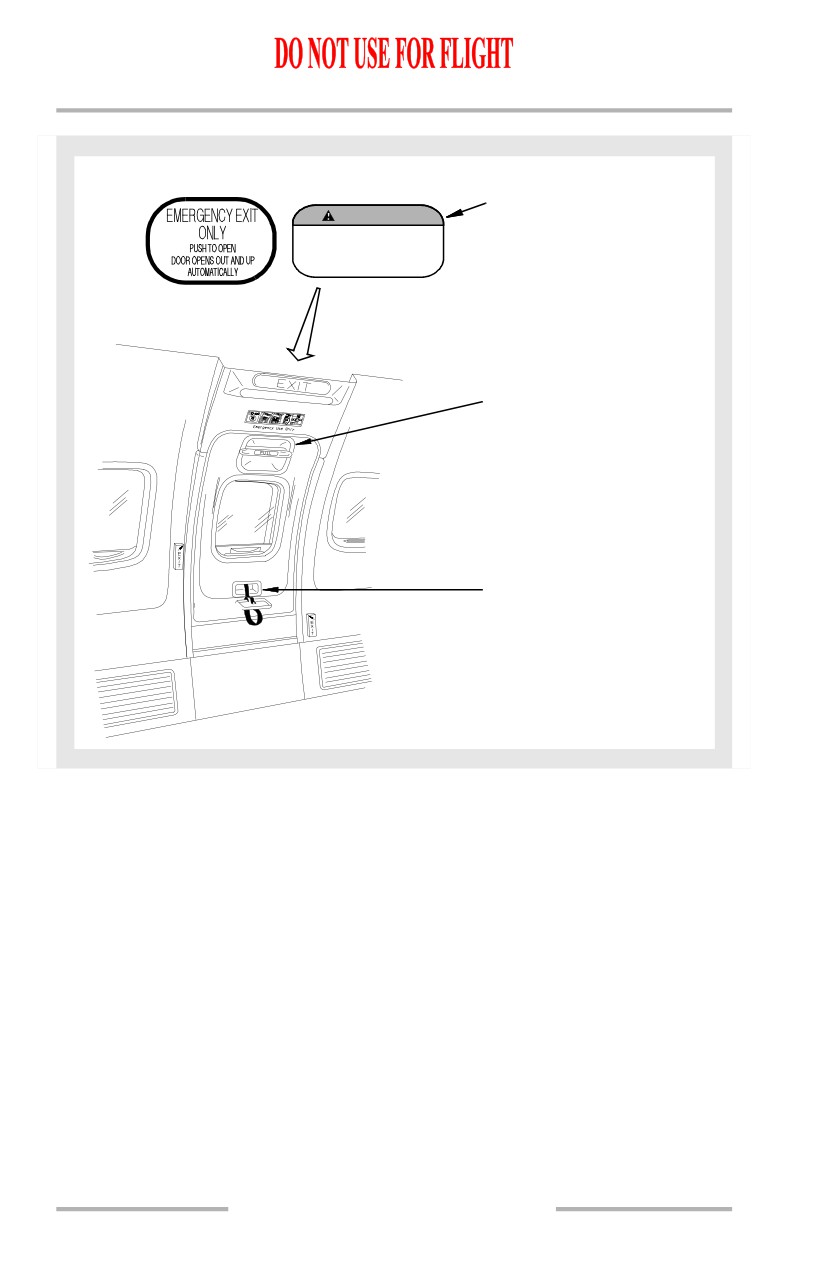
Two Type III emergency exits are located in the passenger cabin over the wings.
These are canopy-type doors and are held in place by mechanical locks and
airplane cabin pressure.
[Option - 737-800/900]
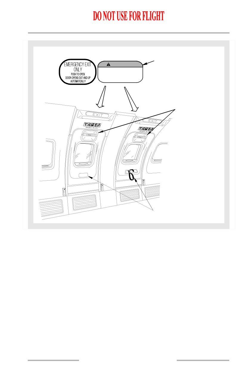
Four Type III emergency exits are located in the passenger cabin over the wings.
These are canopy-type doors and are held in place by mechanical locks and
airplane cabin pressure.
The doors can be opened from inside or outside of the airplane by a spring-loaded
handle at the top of the door. The 28 Volt DC flight lock system is designed to
ensure that the flight lock will automatically lock during takeoff, in-flight, and
landing and unlock on the ground to allow for opening of the door in emergency
situations. Commands for the flight lock to lock and unlock are dependent upon
engine speed, thrust lever position, air/ground mode status, and the open/closed
status of the doors.
The overwing emergency exits lock when:
• three of the four Entry/Service doors are closed and
• either engine is running and
• the airplane air/ground logic indicates that the airplane is in the air or both
thrust levers are advanced.
The overwing emergency exits unlock when any one of the above conditions is not
met or DC power is lost.
The LEFT OVERWING and/or RIGHT OVERWING warning lights, DOORS
annunciator, and MASTER CAUTION light illuminate when an emergency exit
door is not fully closed and locked or when the flight lock is not engaged, either
during the takeoff roll or in-flight.
If a flight lock has failed locked or a fault is detected the PSEU light, the
OVERHEAD annunciator, and the MASTER CAUTION lights illuminate.These
indications are inhibited from takeoff until 30 seconds after the airplane is in the
ground mode. When the doors are latched and locked and the flight lock is
operating properly none of these lights will illuminate.
1.40.33
Airplane General, Emergency
Equipment, Doors, Windows -
Systems Description
Boeing 737 Operations Manual
[Option - 737-600/700]
EXTERIOR PLACARDS
EMERGENCY EXIT DOOR
WARNING
PUSH PANEL
DOORSWINGS OUTANDUP
HOLDYOURKNEEAGAINST DOOR
TO OPEN DOOR
WHILEOPENING OR SERIOUS
INJURY CAN OCCUR
1. Push in panel
2. Door opens out and
up automatically
INTERIOR HANDLE
TO OPEN DOOR
1. Pull handle down
and inward
CLOSING STRAP
1.40.34
Airplane General, Emergency
Equipment, Doors, Windows -
Systems Description
Boeing 737 Operations Manual
[Option - 737-800/900]
EXTERIOR PLACARDS
EMERGENCY EXIT DOORS
WARNING
PUSH PANEL
DOORSWINGS OUTANDUP
HOLDYOURKNEEAGAINSTDOOR
TO OPEN DOOR
WHILEOPENING OR SERIOUS
INJURY CAN OCCUR
1. Push in panel
2. Door opens out and
up automatically
INTERIOR HANDLE
TO OPEN DOOR
1. Pull handle
down and
inward
CLOSING STRAP
1.40.35
Airplane General, Emergency
Equipment, Doors, Windows -
Systems Description
Boeing 737 Operations Manual
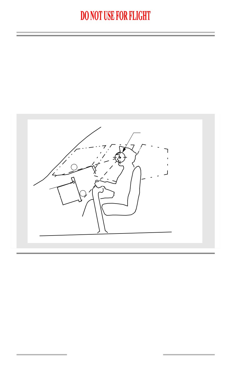
Pilot Seat Adjustment
Adjust the seat position with the appropriate controls to obtain the optimum eye
reference position. Use the handhold above the forward window to assist. The
following sight references are used:
• Sight along the upper surface of the glareshield with a small amount of
the airplane nose structure visible (A)
• Sight over the control column (in the neutral position) until the bottom
edge of the outboard display unit is visible (B).
Pilot Seat Adjustment
EYE REFERENCE POSITION
A
B
Galleys
Galleys are located in the passenger cabin to provide convenient and rapid service
to the passengers. Generally, they are installed in the cabin adjacent to the forward
and aft galley service doors.
In general the equipment of the galley unit consists of the following main items:
• high speed ovens
• hot beverage containers
• hot cup receptacles
• refrigeration and main storage compartments.
1.40.36
Airplane General, Emergency
Equipment, Doors, Windows -
Systems Description
Boeing 737 Operations Manual
Electrical control panel switches and circuit breakers to operate the above
equipment are conveniently located within the galley work area. Storage space,
miscellaneous drawers and waste containers are also integrated in the galley units.
Electrical Power
Electricity for the galleys is 115V AC supplied from the airplane transfer buses
and controlled by a switch on the overhead panel. Circuit breakers are located in
the lower E/E bay as part of the power distribution panels.
Water Service
Water is supplied to the galleys from the airplane pressurized water system and, in
an emergency, may be shut off at the galley.
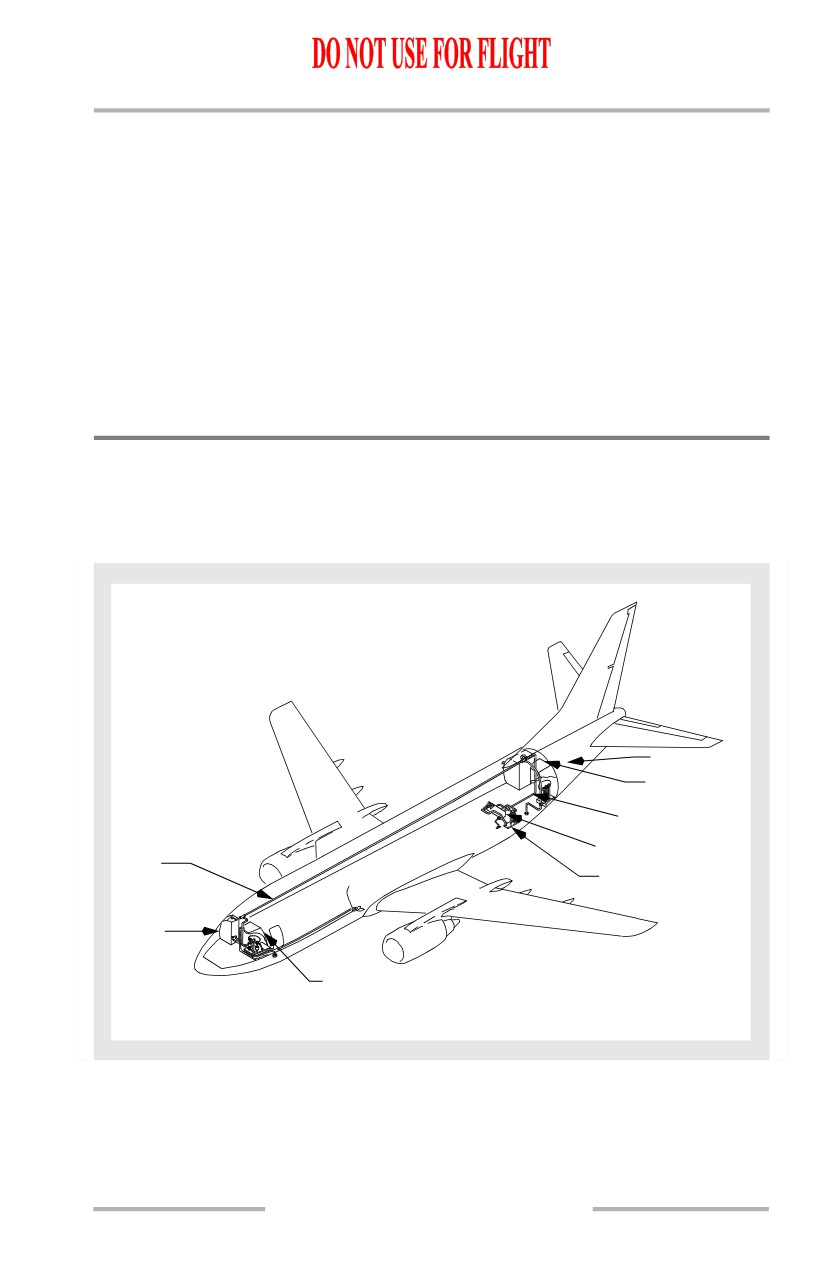
Water System
The potable airplane water system is supplied from a single tank located behind
the aft cargo compartment. Fresh water is supplied to the galleys and lavatory
sinks.
GALLEY
LAVATORY
QUANTITY
INDICATOR
DISTRIBUTION
WATER TANK
LINE
EXTERNAL
SERVICE PANEL
GALLEY
(TYP)
LAVATORY
WATER SYSTEM
1.40.37
Airplane General, Emergency
Equipment, Doors, Windows -
Systems Description
Boeing 737 Operations Manual
Quantity Indication and System Operation
A quantity indicator is located on the attendant panel. The system is pressurized
by engine bleed air or by the water system air compressor. Shutoff valves are
located on each galley and below the sink in each lavatory. The drain position of
this valve is used to drain all water overboard. Normally, the drain shutoff valves
are ON.
Hot Water
Hot and cold water is available in all lavatories. The water heater is located below
the lavatory sink. When emptied, it heats a new water charge in four minutes. An
amber light is ON when the heater is operating normally. The heater has an
overheat switch which turns off the heating element if an excess temperature is
reached. The heater may be turned off at any time by using a manual switch on the
heater. Cold water is supplied at the galleys.
Servicing
The system is serviced from an exterior panel located on the bottom right side of
the aft fuselage. Pressure filling is required. Waste water from the galleys and
lavatory wash basins is drained overboard through two heated drain masts. The
drain masts are on the bottom of the fuselage; one forward and one aft.
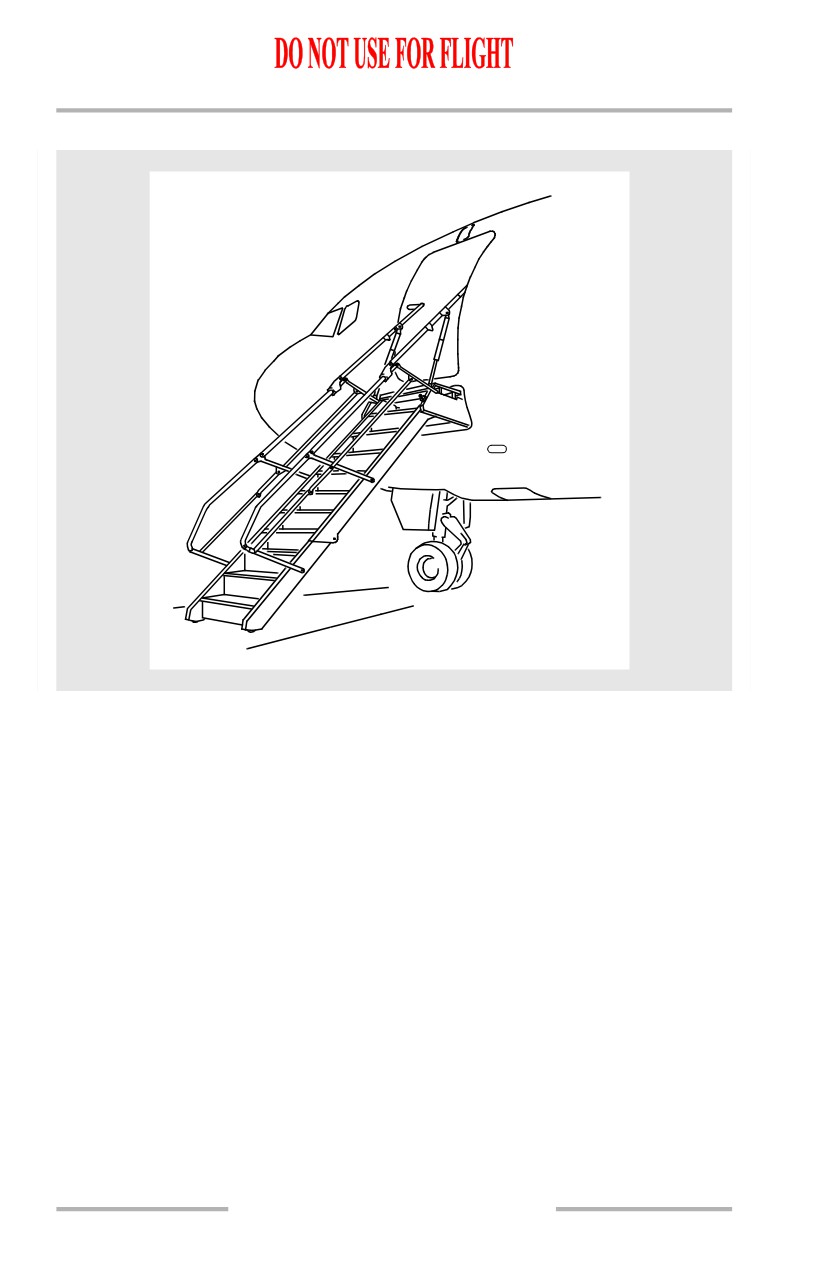
Forward Airstair
[Option - Airstairs]
The forward airstair provides the capability of boarding passengers without
relying on the availability of airport ground equipment. The airstair is electrically
operated and may be controlled from either inside or outside the airplane. The
airstair is stowed inside a compartment just below the forward entry door. The
compartment has a pressure door that automatically opens before the airstair can
operate. For passenger safety, upper handrails are attached to support brackets
inside the entry door after the airstair is fully extended.
1.40.38
Airplane General, Emergency
Equipment, Doors, Windows -
Systems Description
Boeing 737 Operations Manual
Interior Control
The interior control panel is located on the forward attendant panel. A white
STAIR OPER light on the panel illuminates when the airstair is in transit. The
airstair tread lights on the airstair steps are controlled by a single three-position
airstair Tread LIGHTS switch. With the switch in the AUTO position, the tread
lights illuminate when the airstair makes contact with the ground and extinguish
when the airstair retracts. The interior control panel has two modes of operation,
normal and standby. The standby system provides an alternate means of electrical
control in the event the normal mode of operation is not available. Normal
operation requires 115V AC while standby operation requires the battery switch
to be ON. Both operating modes require the forward entry door to be partially
open. During normal operation the momentary extend or retract switches are
depressed to operate the stairs. To operate in the standby mode, the momentary
standby switch must be depressed while the retract or extend switches are also
depressed.
Exterior Control
The exterior control is located to the right and below the airstair compartment.
Operating instructions are located near the switches. When operating the airstair
with the exterior control, the forward entry door need not be open. The exterior
control switch by-passes the door-open requirement. A two-position switch,
labeled NORMAL and STANDBY, is located in the exterior control recess. The
switch is spring-loaded to NORMAL. Holding the NORMAL/STANDBY Switch
to STANDBY provides DC power from the battery bus for airstair operation. The
BAT switch on the flight deck does not need to be ON when operating the airstair
on standby from the exterior control panel. The airstair control switch can be
moved to extend or retract the airstair. The use of the standby system from either
the interior or exterior control by-passes the handrail and lower ladder safety
circuits. Caution must be exercised when using the standby system. If the upper
handrail extensions are not properly stowed before retraction, damage to the
airplane structure or damage to the airstair’s handrail may result. A white
AIRSTAIR light, located on the overhead door caution annunciator panel,
illuminates when the airstair pressure door is unlocked. Illumination of the
AIRSTAIR light also activates the DOORS annunciator light and the MASTER
CAUTION lights. The Airstair light is inoperative when DC bus 1 is not powered.
The MASTER CAUTION and DOORS lights illuminate in normal or standby
operation of the airstair.
1.40.39
Airplane General, Emergency
Equipment, Doors, Windows -
Systems Description
Boeing 737 Operations Manual
Airstairs
1.40.40
Boeing 737 Operations Manual
Air Systems
Chapter 2
Table of Contents
Section 0
2.0 Air Systems-Table of Contents
Controls and Indicators
2.10.1
Bleed Air Controls and Indicators
2.10.1
Air Conditioning Controls and Indicators
2.10.5
Equipment Cooling Panel
2.10.11
Cabin Altitude Panel
2.10.12
Cabin Pressurization Panel
2.10.13
Bleed Air System Description
2.20.1
Introduction
2.20.1
Engine Bleed System Supply
2.20.1
Engine Bleed Air Valves
2.20.1
Bleed Trip Sensors
2.20.1
Duct Pressure Transmitters
2.20.2
Isolation Valve
2.20.2
External Air Connection
2.20.2
APU Bleed Air Valve
2.20.2
DUAL BLEED Light
2.20.2
Bleed Air System Schematic
2.20.3
Wing-Body Overheat
2.20.5
Wing-Body Overheat Ducts and Lights
2.20.5
Air Conditioning System Description
2.30.1
Introduction
2.30.1
Air Conditioning Pack
2.30.1
Airflow Control
2.30.1
Ram Air System
2.30.2
Cooling Cycle
2.30.2
Air Mix Valves
2.30.2
Air Conditioning Pack Schematic
2.30.3
Air Conditioning Distribution
2.30.3
2.TOC.0.1